Embed Size (px)
Citation preview
Village of Crivitz Wellhead Protection Plan – May 21, 2019
VILLAGE OF CRIVITZ WELLHEAD PROTECTION PLAN
WELLS #1 #2 & #3
November, 2008 Updated: May 21, 2019
Prepared for the Village of Crivitz By: Wisconsin Rural Water Association Sourcewater Protection Program Andrew Aslesen, Sourcewater Specialist, [email protected]

Village of Crivitz Wellhead Protection Plan – May 21, 2019
Village of Crivitz Wellhead Protection Plan – May 21, 2019
Table of Contents BACKGROUND ............................................................................................................................................... 1
WATER SUPPLY ......................................................................................................................................... 1
HYDROGEOLOGIC SETTING ............................................................................................................................ 2
GROUNDWATER FLOW DIRECTION ............................................................................................................... 4
ZONE OF INFLUENCE ..................................................................................................................................... 4
ZONE OF CONTRIBUTION (RECHARGE AREA) ................................................................................................ 5
POTENTIAL CONTAMINANT SOURCES ........................................................................................................... 6
WELLHEAD PROTECTION AREAS.................................................................................................................... 8
MANAGEMENT STRATEGY............................................................................................................................. 8
STEERING COMMITTEE ............................................................................................................................. 9
CONTINGENCY PLANNING ........................................................................................................................... 10
REFERENCES ................................................................................................................................................ 19
Figures
Figure 1 – Village of Crivitz Municipal Well Locations .................................................... 11
Figure 2 – Groundwater Flow .......................................................................................... 12
Figure 3 – Zone of Contribution, Well #1 ......................................................................... 13
Figure 4 –Zone of Contribution, Wells #2 & #3 ............................................................... 14
Figure 5 –Potential Contaminant Sources, Well #1 ........................................................ 15
Figure 6 –Potential Contaminant Sources, Wells #2 & #3 .............................................. 16
Figure 7 – Wellhead Protection Area, Well #1 ................................................................ 17
Figure 8 – Wellhead Protection Area, Wells #2 & #3 ...................................................... 18
Appendices
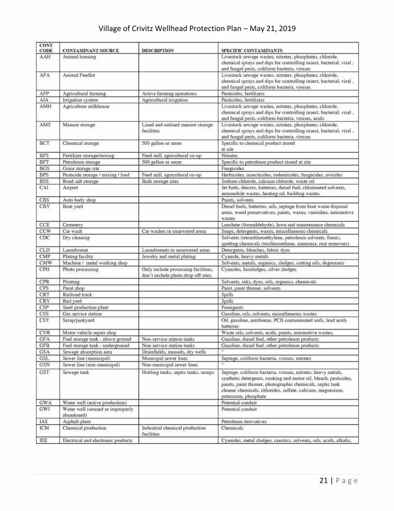
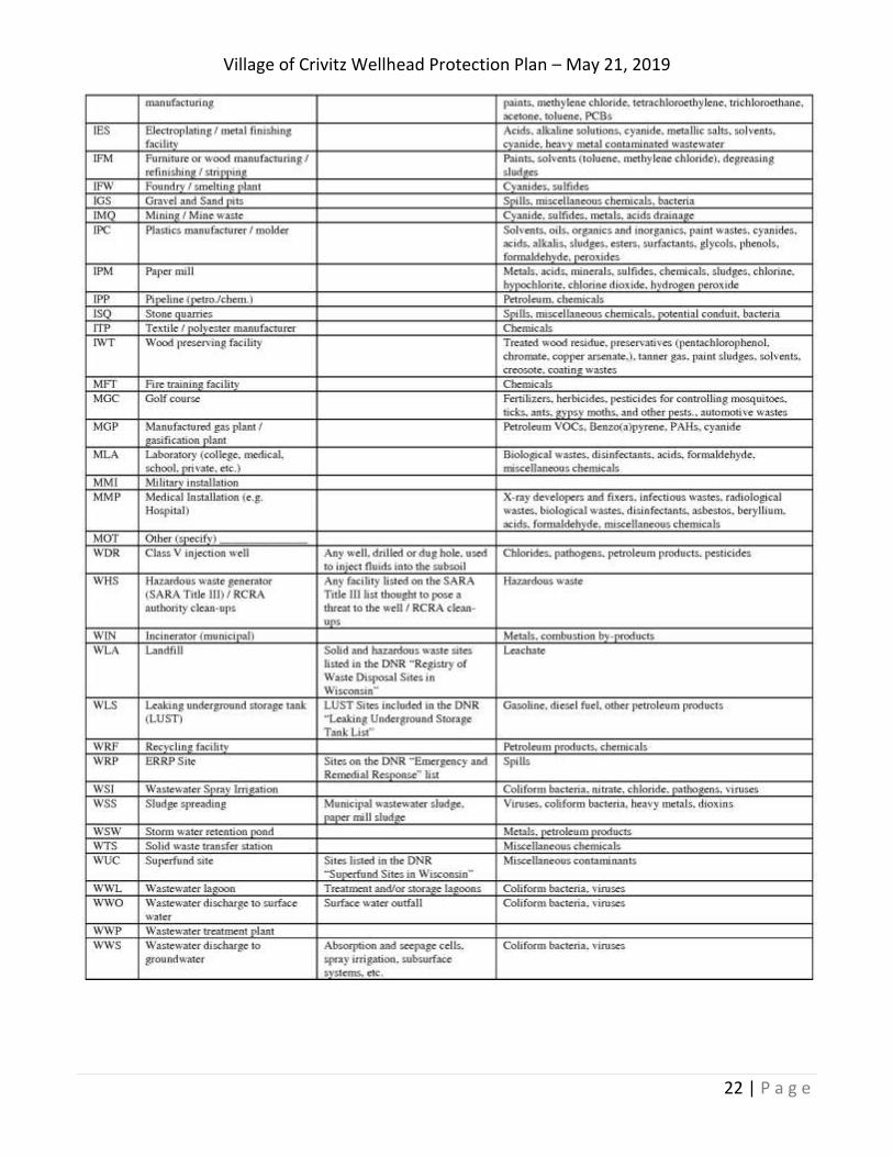
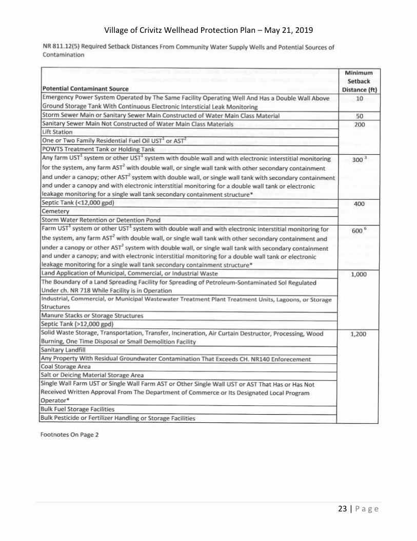
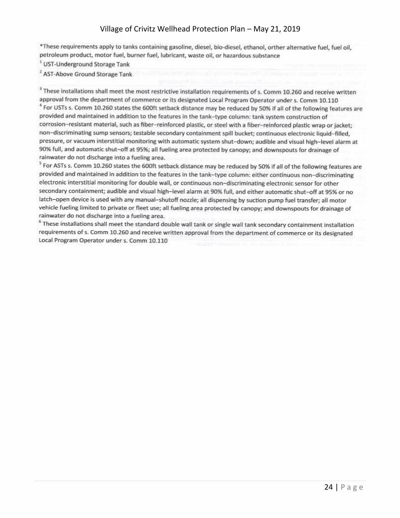
Appendix A – Potential Contaminant Source Inventory, Setbacks & List of Abbreviations
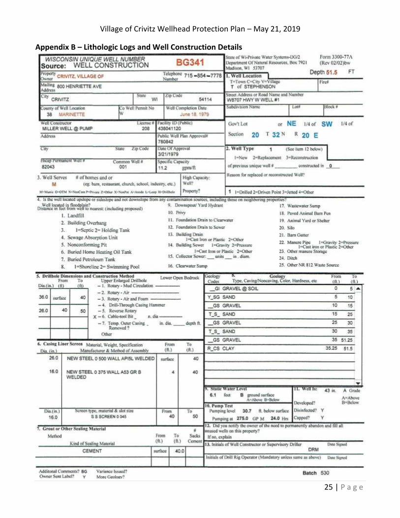
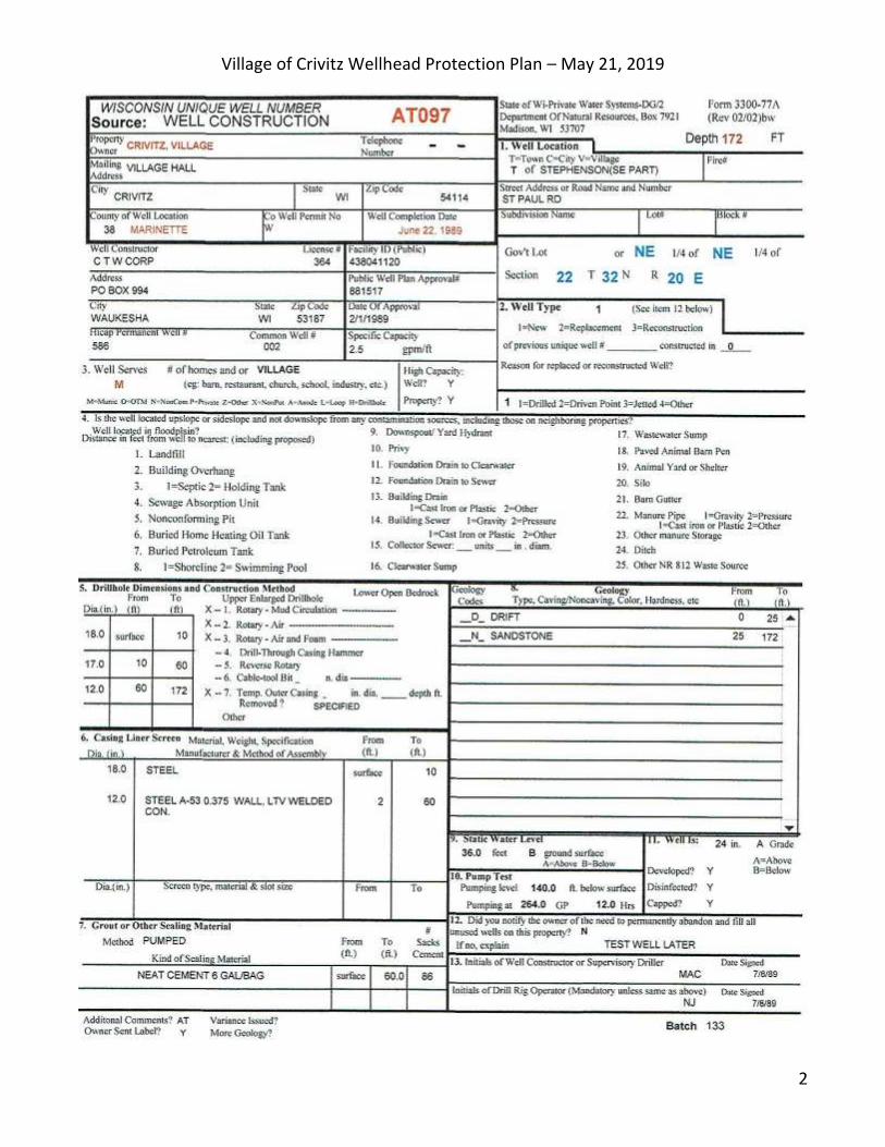
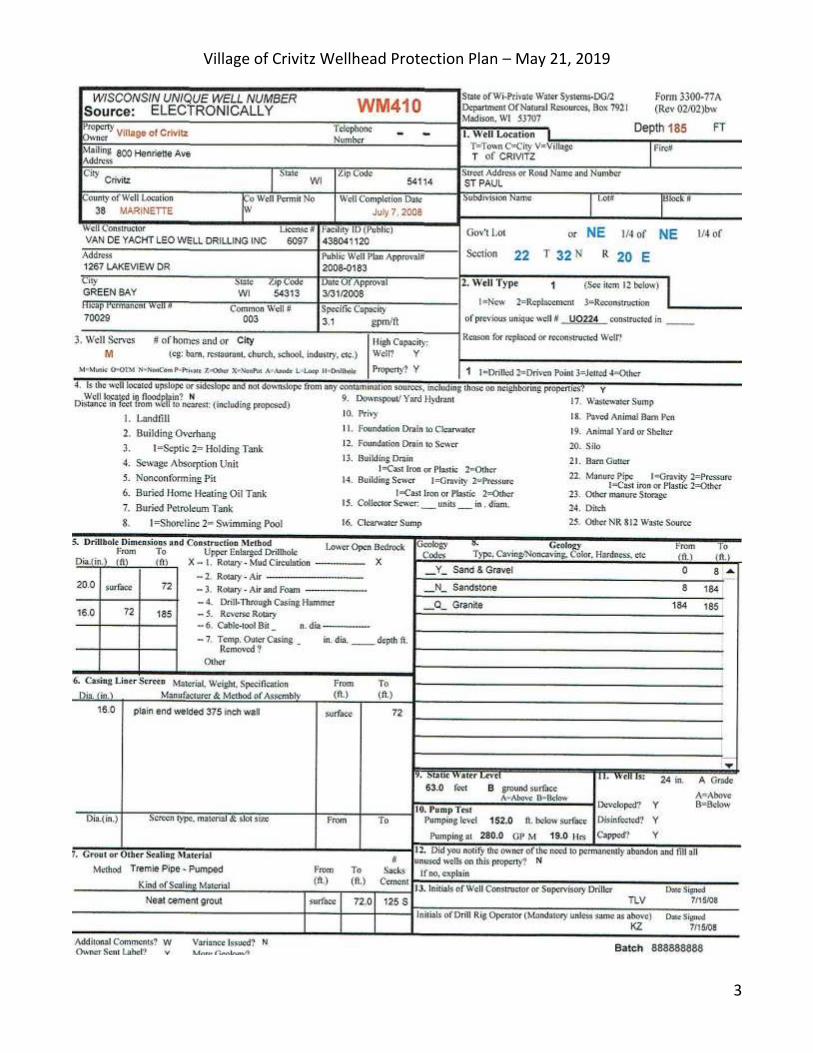
Appendix B – Lithologic Logs And Well Construction Details
Village of Crivitz Wellhead Protection Plan – May 21, 2019
1 | P a g e
BACKGROUND
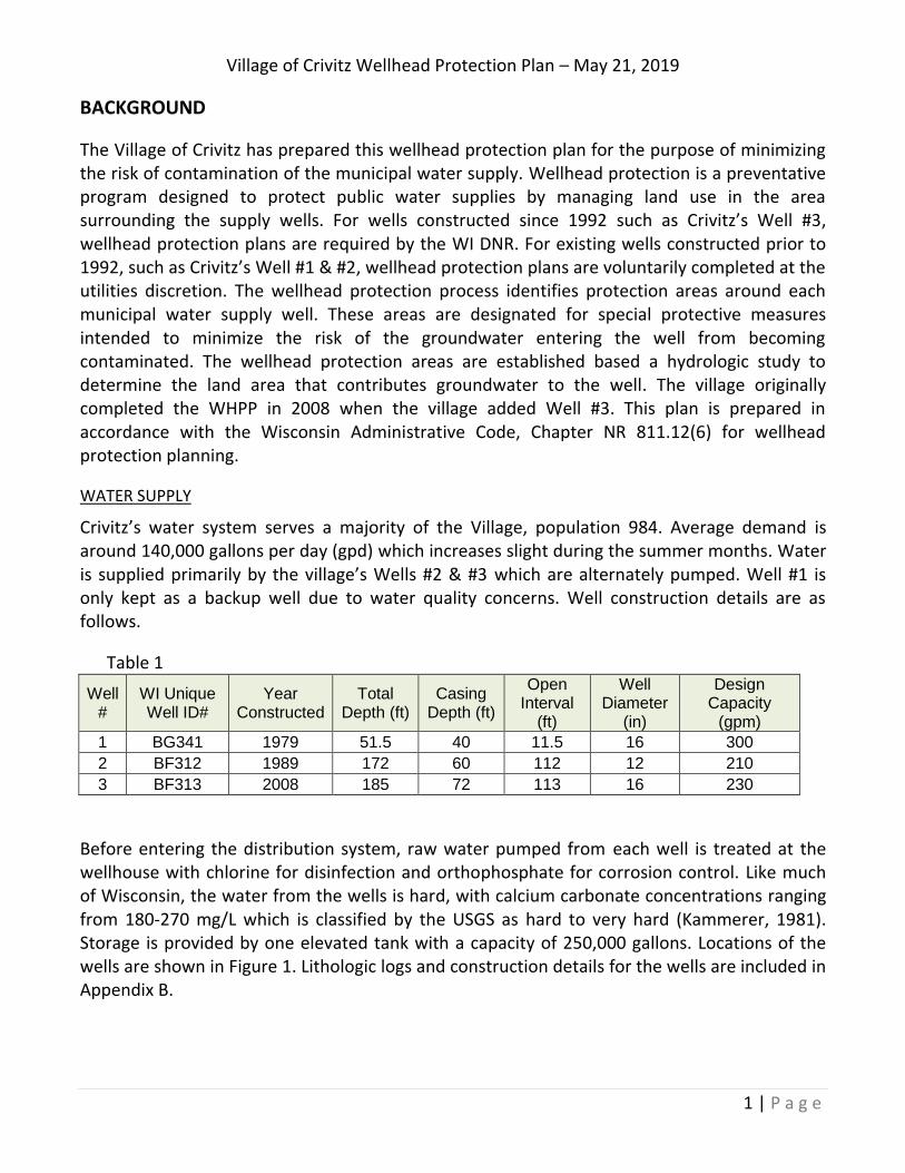
The Village of Crivitz has prepared this wellhead protection plan for the purpose of minimizing the risk of contamination of the municipal water supply. Wellhead protection is a preventative program designed to protect public water supplies by managing land use in the area surrounding the supply wells. For wells constructed since 1992 such as Crivitz’s Well #3, wellhead protection plans are required by the WI DNR. For existing wells constructed prior to 1992, such as Crivitz’s Well #1 & #2, wellhead protection plans are voluntarily completed at the utilities discretion. The wellhead protection process identifies protection areas around each municipal water supply well. These areas are designated for special protective measures intended to minimize the risk of the groundwater entering the well from becoming contaminated. The wellhead protection areas are established based a hydrologic study to determine the land area that contributes groundwater to the well. The village originally completed the WHPP in 2008 when the village added Well #3. This plan is prepared in accordance with the Wisconsin Administrative Code, Chapter NR 811.12(6) for wellhead protection planning.
WATER SUPPLY
Crivitz’s water system serves a majority of the Village, population 984. Average demand is around 140,000 gallons per day (gpd) which increases slight during the summer months. Water is supplied primarily by the village’s Wells #2 & #3 which are alternately pumped. Well #1 is only kept as a backup well due to water quality concerns. Well construction details are as follows.
Table 1
Well #
WI Unique Well ID#
Year Constructed
Total Depth (ft)
Casing Depth (ft)
Open Interval
(ft)
Well Diameter
(in)
Design Capacity
(gpm)
1 BG341 1979 51.5 40 11.5 16 300
2 BF312 1989 172 60 112 12 210
3 BF313 2008 185 72 113 16 230
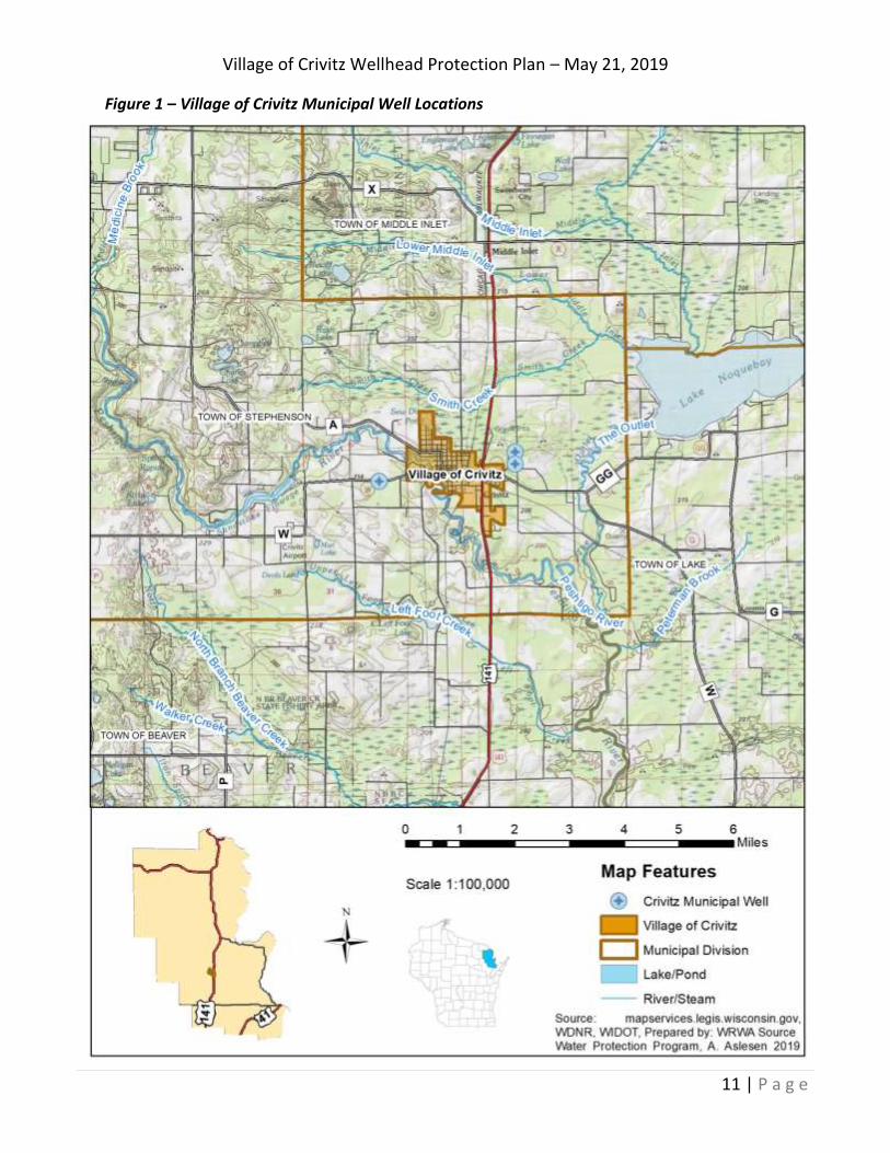
Before entering the distribution system, raw water pumped from each well is treated at the wellhouse with chlorine for disinfection and orthophosphate for corrosion control. Like much of Wisconsin, the water from the wells is hard, with calcium carbonate concentrations ranging from 180-270 mg/L which is classified by the USGS as hard to very hard (Kammerer, 1981). Storage is provided by one elevated tank with a capacity of 250,000 gallons. Locations of the wells are shown in Figure 1. Lithologic logs and construction details for the wells are included in Appendix B.
Village of Crivitz Wellhead Protection Plan – May 21, 2019
2 | P a g e
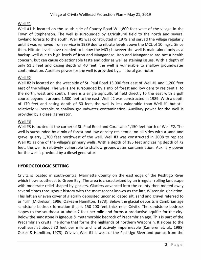
Well #1 Well #1 is located on the south side of County Road W 1,800 feet west of the village in the Town of Stephenson. The well is surrounded by agricultural field to the north and several lowland forests to the south. Well #1 was constructed in 1979 and served the village regularly until it was removed from service in 1989 due to nitrate levels above the MCL of 10 mg/L. Since then, Nitrate levels have receded to below the MCL; however the well is maintained only as a backup well due to high levels of Iron and Manganese. Iron and Manganese are not a health concern, but can cause objectionable taste and odor as well as staining issues. With a depth of only 51.5 feet and casing depth of 40 feet, the well is vulnerable to shallow groundwater contamination. Auxiliary power for the well is provided by a natural gas motor.
Well #2 Well #2 is located on the west side of St. Paul Road 13,000 feet east of Well #1 and 1,200 feet east of the village. The wells are surrounded by a mix of forest and low density residential to the north, west and south. There is a single agricultural field directly to the east with a golf course beyond it around 1,500 feet to the east. Well #2 was constructed in 1989. With a depth of 170 feet and casing depth of 60 feet, the well is less vulnerable than Well #1 but still relatively vulnerable to shallow groundwater contamination. Auxiliary power for the well is provided by a diesel generator.
Well #3 Well #3 is located at the corner of St. Paul Road and Cora Lane 1,150 feet north of Well #2. The well is surrounded by a mix of forest and low density residential on all sides with a sand and gravel quarry 1,700 feet northwest of the well. Well #3 was constructed in 2008 to replace Well #1 as one of the village’s primary wells. With a depth of 185 feet and casing depth of 72 feet, the well is relatively vulnerable to shallow groundwater contamination. Auxiliary power for the well is provided by a diesel generator.
HYDROGEOLOGIC SETTING
Crivitz is located in south-central Marinette County on the east edge of the Peshtigo River which flows southeast to Green Bay. The area is characterized by an irregular rolling landscape with moderate relief shaped by glaciers. Glaciers advanced into the county then melted away several times throughout history with the most recent known as the late Wisconsin glaciation. This left an uneven cover of glacially deposited unconsolidated silt, sand and gravel referred to as “till” (Mickelson, 1986; Oakes & Hamilton, 1973). Below the glacial deposits is Cambrian age sandstone bedrock formation that is 150-200 feet thick near Crivitz. The sandstone bedrock slopes to the southeast at about 7 feet per mile and forms a productive aquifer for the city. Below the sandstone is igneous & metamorphic bedrock of Precambrian age. This is part of the Precambrian crystalline dome that forms the highlands of northern Wisconsin. It slopes to the southeast at about 30 feet per mile and is effectively impermeable (Kamerer et. al., 1998; Oakes & Hamilton, 1973). Crivitz’s Well #1 is west of the Peshtigo River and pumps from the
Village of Crivitz Wellhead Protection Plan – May 21, 2019
3 | P a g e
unconsolidated glacial aquifer. Wells #2 & #3 are east of the Peshtigo River and pump from the Cambrian sandstone aquifer.
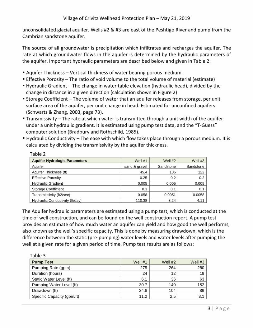
The source of all groundwater is precipitation which infiltrates and recharges the aquifer. The rate at which groundwater flows in the aquifer is determined by the hydraulic parameters of the aquifer. Important hydraulic parameters are described below and given in Table 2:
Aquifer Thickness – Vertical thickness of water bearing porous medium. Effective Porosity – The ratio of void volume to the total volume of material (estimate) Hydraulic Gradient – The change in water table elevation (hydraulic head), divided by the
change in distance in a given direction (calculation shown in Figure 2) Storage Coefficient – The volume of water that an aquifer releases from storage, per unit
surface area of the aquifer, per unit change in head. Estimated for unconfined aquifers (Schwartz & Zhang, 2003, page 73).
Transmissivity – The rate at which water is transmitted through a unit width of the aquifer under a unit hydraulic gradient. It is estimated using pump test data, and the “T-Guess” computer solution (Bradbury and Rothschild, 1985).
Hydraulic Conductivity – The ease with which flow takes place through a porous medium. It is calculated by dividing the transmissivity by the aquifer thickness.
Table 2 Aquifer Hydrologic Parameters Well #1 Well #2 Well #3
Aquifer sand & gravel Sandstone Sandstone
Aquifer Thickness (ft) 45.4 136 122
Effective Porosity 0.25 0.2 0.2
Hydraulic Gradient 0.005 0.005 0.005
Storage Coefficient 0.1 0.1 0.1
Transmissivity (ft2/sec) 0.058 0.0051 0.0058
Hydraulic Conductivity (ft/day) 110.38 3.24 4.11
The Aquifer hydraulic parameters are estimated using a pump test, which is conducted at the time of well construction, and can be found on the well construction report. A pump test provides an estimate of how much water an aquifer can yield and how good the well performs, also known as the well’s specific capacity. This is done by measuring drawdown, which is the difference between the static (pre-pumping) water levels and water levels after pumping the well at a given rate for a given period of time. Pump test results are as follows:
Table 3 Pump Test Well #1 Well #2 Well #3
Pumping Rate (gpm) 275 264 280
Duration (hours) 24 12 19
Static Water Level (ft) 6.1 36 63
Pumping Water Level (ft) 30.7 140 152
Drawdown (ft) 24.6 104 89
Specific Capacity (gpm/ft) 11.2 2.5 3.1
Village of Crivitz Wellhead Protection Plan – May 21, 2019
4 | P a g e
GROUNDWATER FLOW DIRECTION
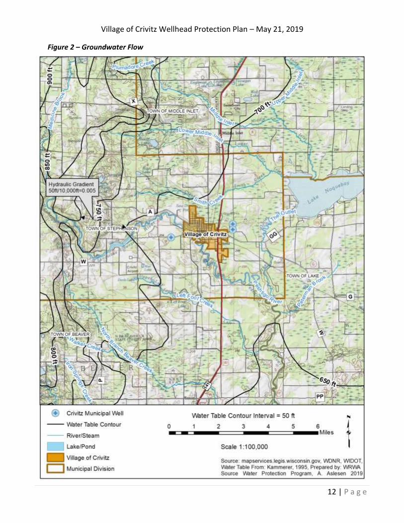
In a groundwater flow system, groundwater moves continuously from areas of recharge to areas of discharge. The direction of groundwater flow may be inferred from the regional topography and the slope of the water table. The water table is the upper limit of the aquifer and is measured in “head” or elevation above sea level. The water table is estimated by looking at water levels in wells that have a screened interval within the aquifer, which provide a point of measurement of water table elevation. The best available water table map for the area was developed for by the U.S. Geological Survey (Kammerer, 1995). The water table is shown as contour lines of equal head with a 50 ft contour interval. Groundwater flows approximately at right angles to the contour lines of equal head in the direction of decreasing head. In general groundwater divides coincide with surface water divides. Groundwater in the Peshtigo river basin flows from west to east along relatively short flow paths away from topographically high areas to low areas where it discharges into lakes, streams and wetlands. Groundwater captured by Well #1 originates primarily to the west/southwest of the well and flows east/northeast towards the Peshtigo River. Groundwater captured by Wells #2& #3 originates primarily to the north of the wells and flows south towards the Peshtigo River and it’s tributaries. A local portion of the water table map is shown in Figure 2.
ZONE OF INFLUENCE
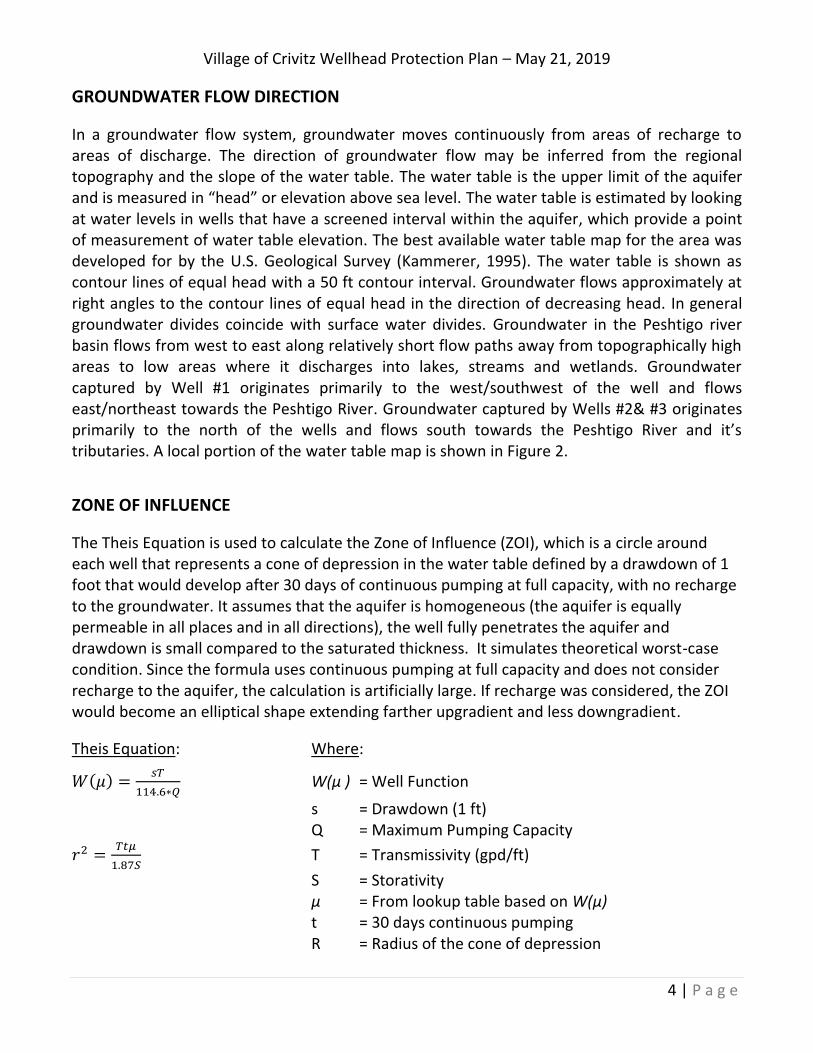
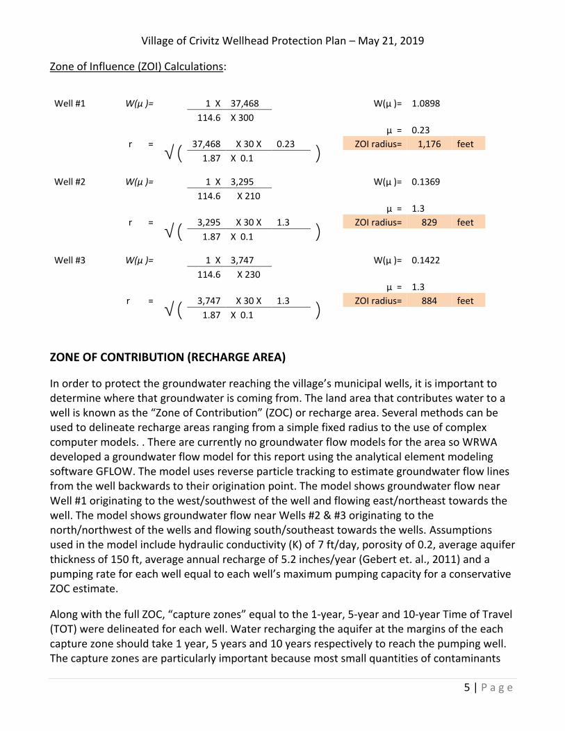
The Theis Equation is used to calculate the Zone of Influence (ZOI), which is a circle around each well that represents a cone of depression in the water table defined by a drawdown of 1 foot that would develop after 30 days of continuous pumping at full capacity, with no recharge to the groundwater. It assumes that the aquifer is homogeneous (the aquifer is equally permeable in all places and in all directions), the well fully penetrates the aquifer and drawdown is small compared to the saturated thickness. It simulates theoretical worst-case condition. Since the formula uses continuous pumping at full capacity and does not consider recharge to the aquifer, the calculation is artificially large. If recharge was considered, the ZOI would become an elliptical shape extending farther upgradient and less downgradient.
Theis Equation: Where:
𝑊(𝜇) =𝑠𝑇
114.6∗𝑄 W(μ ) = Well Function
s = Drawdown (1 ft) Q = Maximum Pumping Capacity
𝑟2 =𝑇𝑡𝜇
1.87𝑆 T = Transmissivity (gpd/ft)
S = Storativity μ = From lookup table based on W(μ) t = 30 days continuous pumping R = Radius of the cone of depression
Village of Crivitz Wellhead Protection Plan – May 21, 2019
5 | P a g e
Zone of Influence (ZOI) Calculations:
Well #1 W(μ )=
1 X 37,468
W(μ )= 1.0898
114.6 X 300
μ = 0.23
r =
√( 37,468 X 30 X 0.23
) ZOI radius= 1,176 feet
1.87 X 0.1
Well #2 W(μ )=
1 X 3,295
W(μ )= 0.1369
114.6 X 210
μ = 1.3
r =
√( 3,295 X 30 X 1.3
) ZOI radius= 829 feet
1.87 X 0.1
Well #3 W(μ )=
1 X 3,747
W(μ )= 0.1422
114.6 X 230
μ = 1.3
r =
√( 3,747 X 30 X 1.3
) ZOI radius= 884 feet
1.87 X 0.1
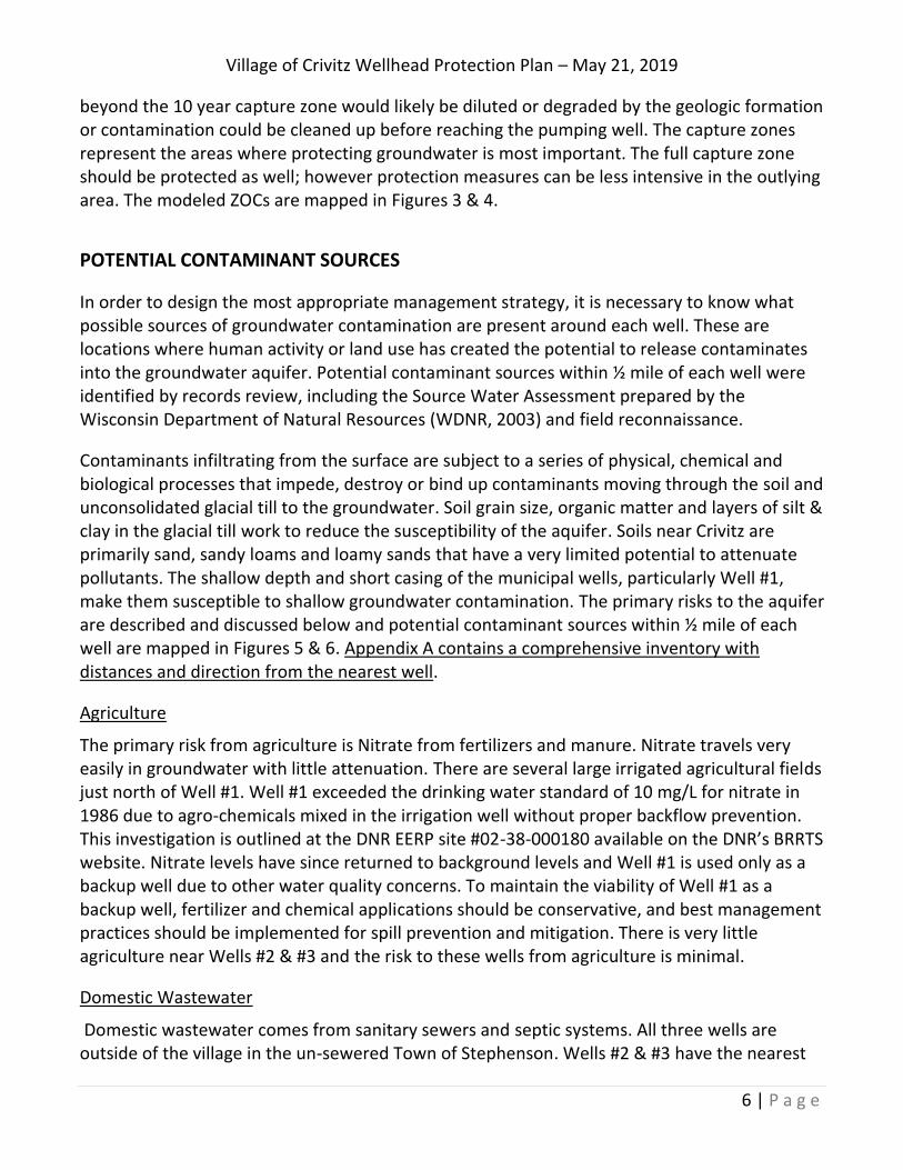
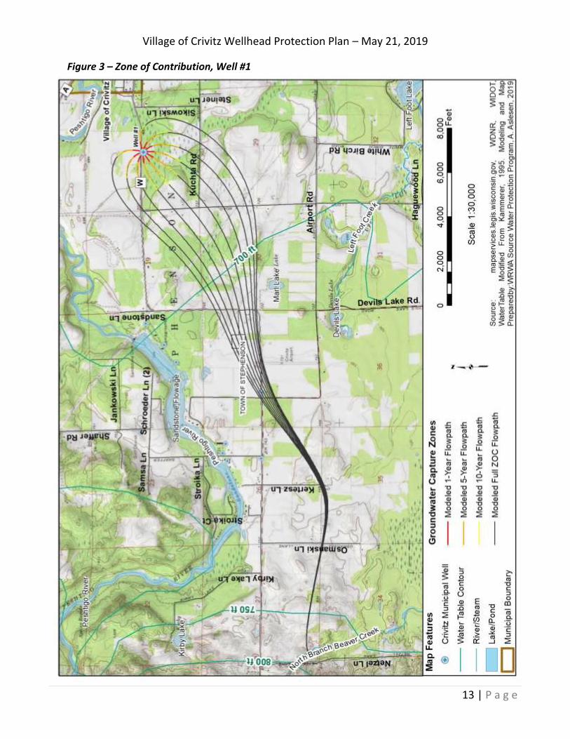
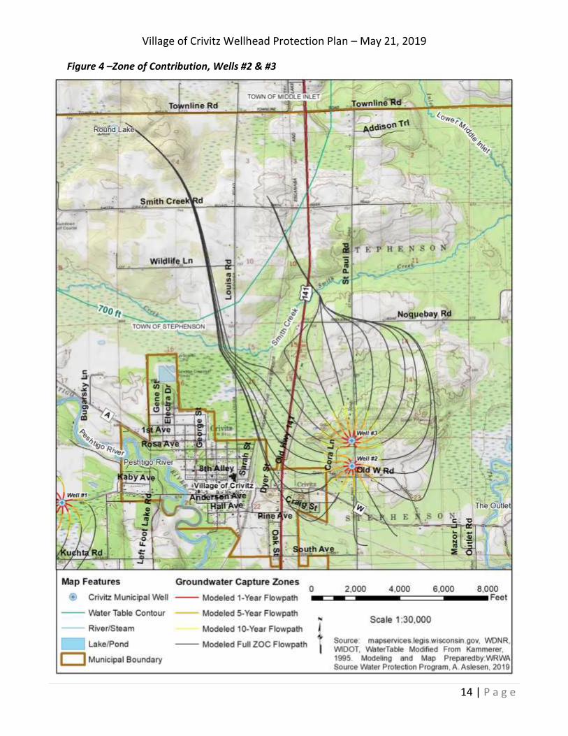
ZONE OF CONTRIBUTION (RECHARGE AREA)
In order to protect the groundwater reaching the village’s municipal wells, it is important to determine where that groundwater is coming from. The land area that contributes water to a well is known as the “Zone of Contribution” (ZOC) or recharge area. Several methods can be used to delineate recharge areas ranging from a simple fixed radius to the use of complex computer models. . There are currently no groundwater flow models for the area so WRWA developed a groundwater flow model for this report using the analytical element modeling software GFLOW. The model uses reverse particle tracking to estimate groundwater flow lines from the well backwards to their origination point. The model shows groundwater flow near Well #1 originating to the west/southwest of the well and flowing east/northeast towards the well. The model shows groundwater flow near Wells #2 & #3 originating to the north/northwest of the wells and flowing south/southeast towards the wells. Assumptions used in the model include hydraulic conductivity (K) of 7 ft/day, porosity of 0.2, average aquifer thickness of 150 ft, average annual recharge of 5.2 inches/year (Gebert et. al., 2011) and a pumping rate for each well equal to each well’s maximum pumping capacity for a conservative ZOC estimate.
Along with the full ZOC, “capture zones” equal to the 1-year, 5-year and 10-year Time of Travel (TOT) were delineated for each well. Water recharging the aquifer at the margins of the each capture zone should take 1 year, 5 years and 10 years respectively to reach the pumping well. The capture zones are particularly important because most small quantities of contaminants
Village of Crivitz Wellhead Protection Plan – May 21, 2019
6 | P a g e
beyond the 10 year capture zone would likely be diluted or degraded by the geologic formation or contamination could be cleaned up before reaching the pumping well. The capture zones represent the areas where protecting groundwater is most important. The full capture zone should be protected as well; however protection measures can be less intensive in the outlying area. The modeled ZOCs are mapped in Figures 3 & 4.
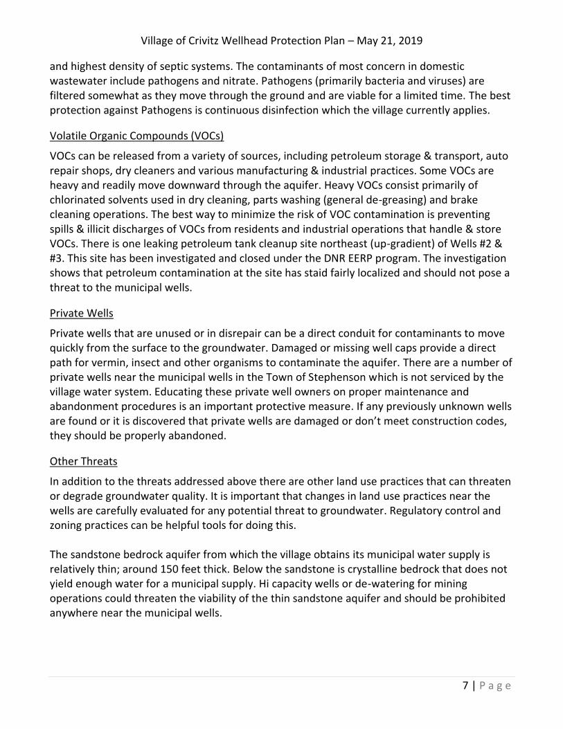
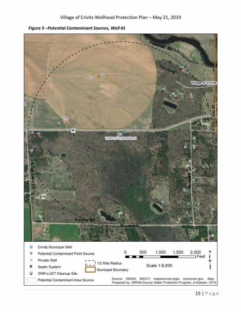
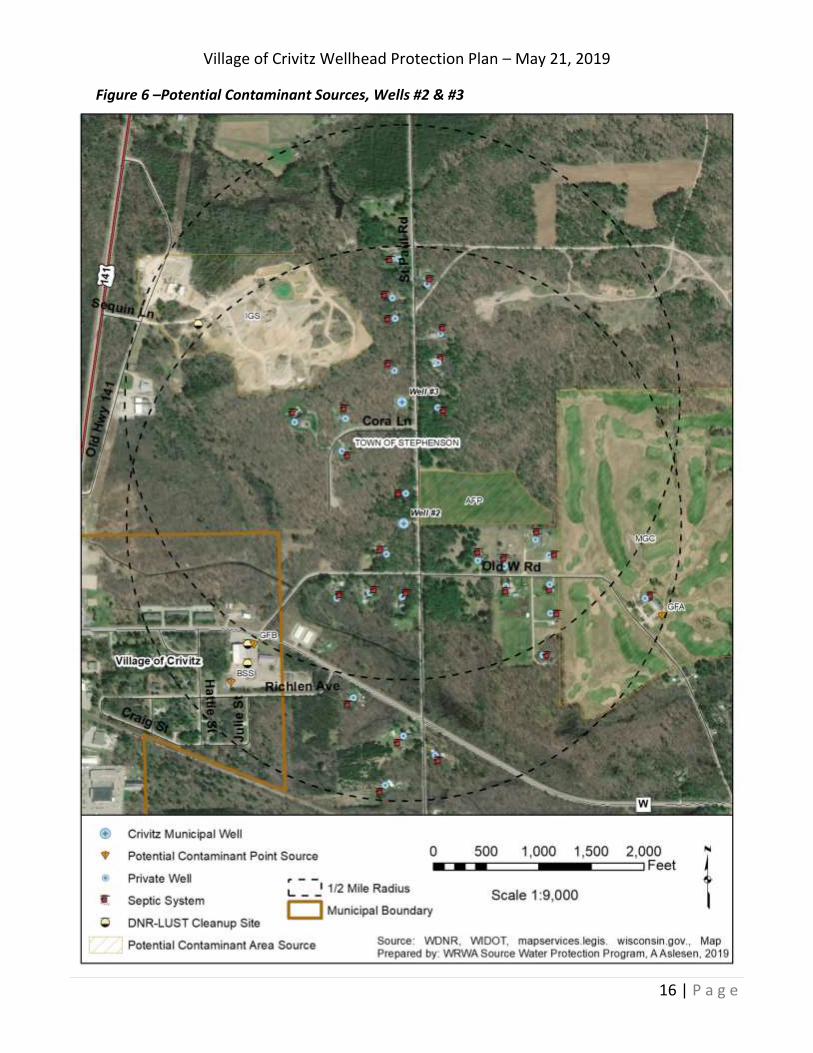
POTENTIAL CONTAMINANT SOURCES
In order to design the most appropriate management strategy, it is necessary to know what possible sources of groundwater contamination are present around each well. These are locations where human activity or land use has created the potential to release contaminates into the groundwater aquifer. Potential contaminant sources within ½ mile of each well were identified by records review, including the Source Water Assessment prepared by the Wisconsin Department of Natural Resources (WDNR, 2003) and field reconnaissance.
Contaminants infiltrating from the surface are subject to a series of physical, chemical and biological processes that impede, destroy or bind up contaminants moving through the soil and unconsolidated glacial till to the groundwater. Soil grain size, organic matter and layers of silt & clay in the glacial till work to reduce the susceptibility of the aquifer. Soils near Crivitz are primarily sand, sandy loams and loamy sands that have a very limited potential to attenuate pollutants. The shallow depth and short casing of the municipal wells, particularly Well #1, make them susceptible to shallow groundwater contamination. The primary risks to the aquifer are described and discussed below and potential contaminant sources within ½ mile of each well are mapped in Figures 5 & 6. Appendix A contains a comprehensive inventory with distances and direction from the nearest well.
Agriculture
The primary risk from agriculture is Nitrate from fertilizers and manure. Nitrate travels very easily in groundwater with little attenuation. There are several large irrigated agricultural fields just north of Well #1. Well #1 exceeded the drinking water standard of 10 mg/L for nitrate in 1986 due to agro-chemicals mixed in the irrigation well without proper backflow prevention. This investigation is outlined at the DNR EERP site #02-38-000180 available on the DNR’s BRRTS website. Nitrate levels have since returned to background levels and Well #1 is used only as a backup well due to other water quality concerns. To maintain the viability of Well #1 as a backup well, fertilizer and chemical applications should be conservative, and best management practices should be implemented for spill prevention and mitigation. There is very little agriculture near Wells #2 & #3 and the risk to these wells from agriculture is minimal.
Domestic Wastewater
Domestic wastewater comes from sanitary sewers and septic systems. All three wells are outside of the village in the un-sewered Town of Stephenson. Wells #2 & #3 have the nearest
Village of Crivitz Wellhead Protection Plan – May 21, 2019
7 | P a g e
and highest density of septic systems. The contaminants of most concern in domestic wastewater include pathogens and nitrate. Pathogens (primarily bacteria and viruses) are filtered somewhat as they move through the ground and are viable for a limited time. The best protection against Pathogens is continuous disinfection which the village currently applies.
Volatile Organic Compounds (VOCs)
VOCs can be released from a variety of sources, including petroleum storage & transport, auto repair shops, dry cleaners and various manufacturing & industrial practices. Some VOCs are heavy and readily move downward through the aquifer. Heavy VOCs consist primarily of chlorinated solvents used in dry cleaning, parts washing (general de-greasing) and brake cleaning operations. The best way to minimize the risk of VOC contamination is preventing spills & illicit discharges of VOCs from residents and industrial operations that handle & store VOCs. There is one leaking petroleum tank cleanup site northeast (up-gradient) of Wells #2 & #3. This site has been investigated and closed under the DNR EERP program. The investigation shows that petroleum contamination at the site has staid fairly localized and should not pose a threat to the municipal wells.
Private Wells
Private wells that are unused or in disrepair can be a direct conduit for contaminants to move quickly from the surface to the groundwater. Damaged or missing well caps provide a direct path for vermin, insect and other organisms to contaminate the aquifer. There are a number of private wells near the municipal wells in the Town of Stephenson which is not serviced by the village water system. Educating these private well owners on proper maintenance and abandonment procedures is an important protective measure. If any previously unknown wells are found or it is discovered that private wells are damaged or don’t meet construction codes, they should be properly abandoned.
Other Threats
In addition to the threats addressed above there are other land use practices that can threaten or degrade groundwater quality. It is important that changes in land use practices near the wells are carefully evaluated for any potential threat to groundwater. Regulatory control and zoning practices can be helpful tools for doing this. The sandstone bedrock aquifer from which the village obtains its municipal water supply is relatively thin; around 150 feet thick. Below the sandstone is crystalline bedrock that does not yield enough water for a municipal supply. Hi capacity wells or de-watering for mining operations could threaten the viability of the thin sandstone aquifer and should be prohibited anywhere near the municipal wells.
Village of Crivitz Wellhead Protection Plan – May 21, 2019
8 | P a g e
WELLHEAD PROTECTION AREAS
A Wellhead Protection Area (WHPA) is defined by the federal Safe Drinking Water Act as the "surface and subsurface area surrounding a water well or well field, supplying a public water system, through which contaminants are reasonably likely to move toward and reach such water or well field". In practical terms, the WHPA is a legally-defined area including all or part of the Zone of Contribution and within which zoning practices or other land-use controls can be implemented to help protect groundwater from contamination (Bradbury et. al., 1999). The WHPA’s are established to clearly define the area most critical for protecting the village wells from contamination. They should be the primary focus of efforts to protect the Village water supply.
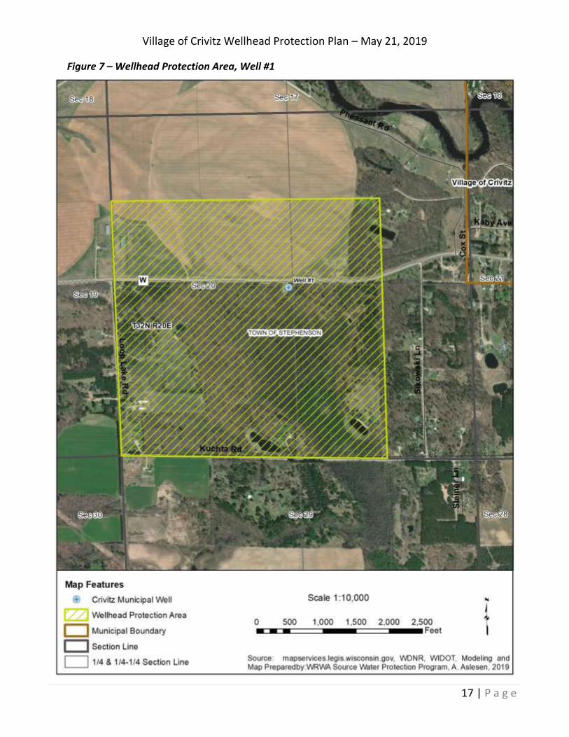
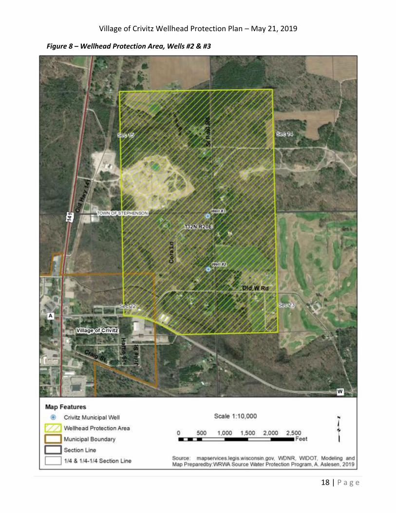
The WHPA’s for Crivitz are established based on the 10-year capture zones. The DNR suggests the boundary of a WHPA be extended to a minimum distance of 1,200 ft around municipal wells. Additionally, the wellhead protection area has been normalized to the nearest PLSS lines and road centerlines for ease of implementation. The wellhead protection area for Well #1 is shown in figure 7 and the wellhead protection area for Wells #2 & #3 is shown in figure 8.
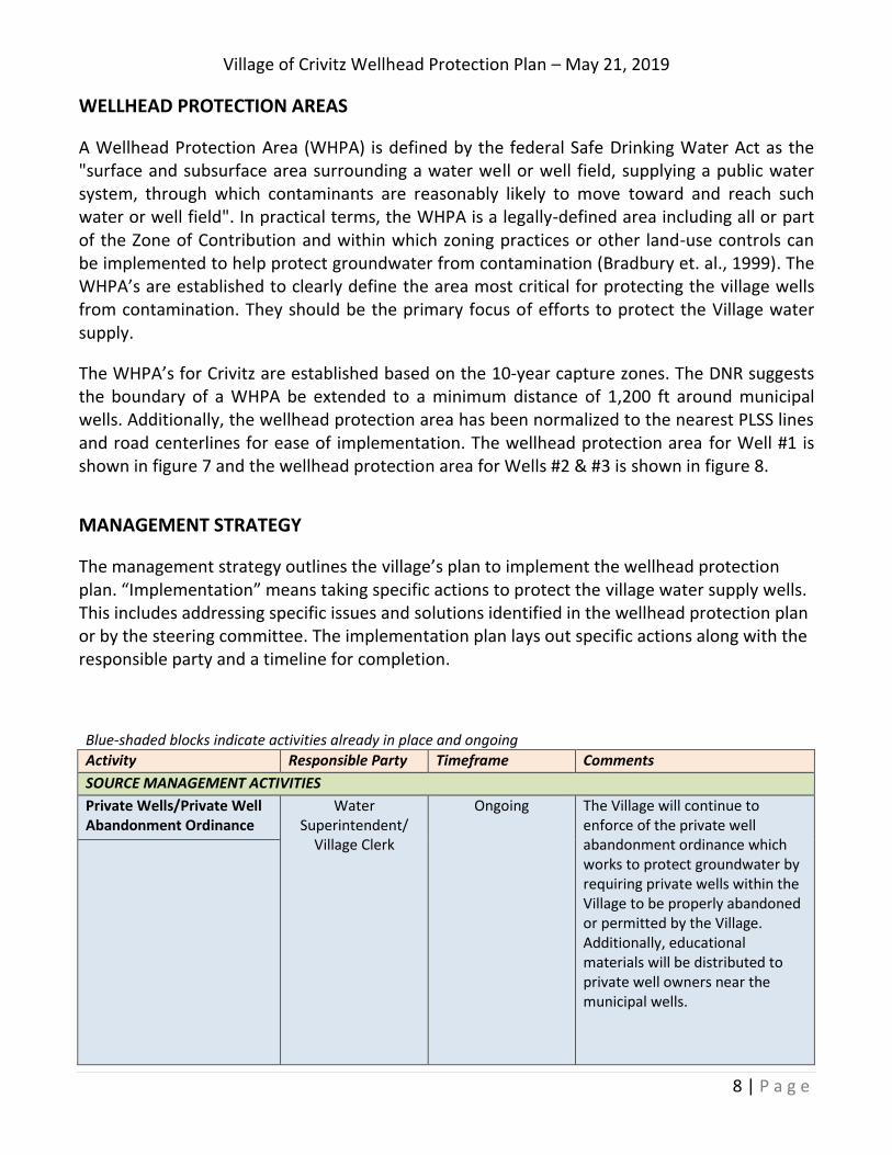
MANAGEMENT STRATEGY
The management strategy outlines the village’s plan to implement the wellhead protection plan. “Implementation” means taking specific actions to protect the village water supply wells. This includes addressing specific issues and solutions identified in the wellhead protection plan or by the steering committee. The implementation plan lays out specific actions along with the responsible party and a timeline for completion.
Blue-shaded blocks indicate activities already in place and ongoing Activity Responsible Party Timeframe Comments
SOURCE MANAGEMENT ACTIVITIES
Private Wells/Private Well Abandonment Ordinance
Water Superintendent/
Village Clerk
Ongoing The Village will continue to enforce of the private well abandonment ordinance which works to protect groundwater by requiring private wells within the Village to be properly abandoned or permitted by the Village. Additionally, educational materials will be distributed to private well owners near the municipal wells.
Village of Crivitz Wellhead Protection Plan – May 21, 2019
9 | P a g e
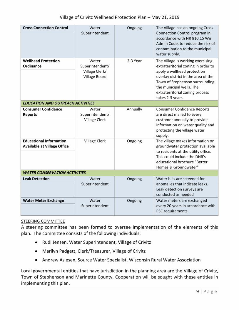
Cross Connection Control Water Superintendent
Ongoing The Village has an ongoing Cross Connection Control program in, accordance with NR 810.15 Wis Admin Code, to reduce the risk of contamination to the municipal water supply.
Wellhead Protection Ordinance
Water Superintendent/
Village Clerk/ Village Board
2-3 Year The Village is working exercising extraterritorial zoning in order to apply a wellhead protection overlay district in the area of the Town of Stephenson surrounding the municipal wells. The extraterritorial zoning process takes 2-3 years.
EDUCATION AND OUTREACH ACTIVITIES
Consumer Confidence Reports
Water Superintendent/
Village Clerk
Annually Consumer Confidence Reports are direct mailed to every customer annually to provide information on water quality and protecting the village water supply.
Educational Information Available at Village Office
Village Clerk Ongoing The village makes information on groundwater protection available to residents at the utility office. This could include the DNR's educational brochure "Better Homes & Groundwater"
WATER CONSERVATION ACTIVITIES
Leak Detection Water Superintendent
Ongoing Water bills are screened for anomalies that indicate leaks. Leak detection surveys are conducted as needed
Water Meter Exchange Water Superintendent
Ongoing Water meters are exchanged every 20 years in accordance with PSC requirements.
STEERING COMMITTEE
A steering committee has been formed to oversee implementation of the elements of this plan. The committee consists of the following individuals:
Rudi Jensen, Water Superintendent, Village of Crivitz
Marilyn Padgett, Clerk/Treasurer, Village of Crivitz
Andrew Aslesen, Source Water Specialist, Wisconsin Rural Water Association
Local governmental entities that have jurisdiction in the planning area are the Village of Crivitz, Town of Stephenson and Marinette County. Cooperation will be sought with these entities in implementing this plan.
Village of Crivitz Wellhead Protection Plan – May 21, 2019
10 | P a g e
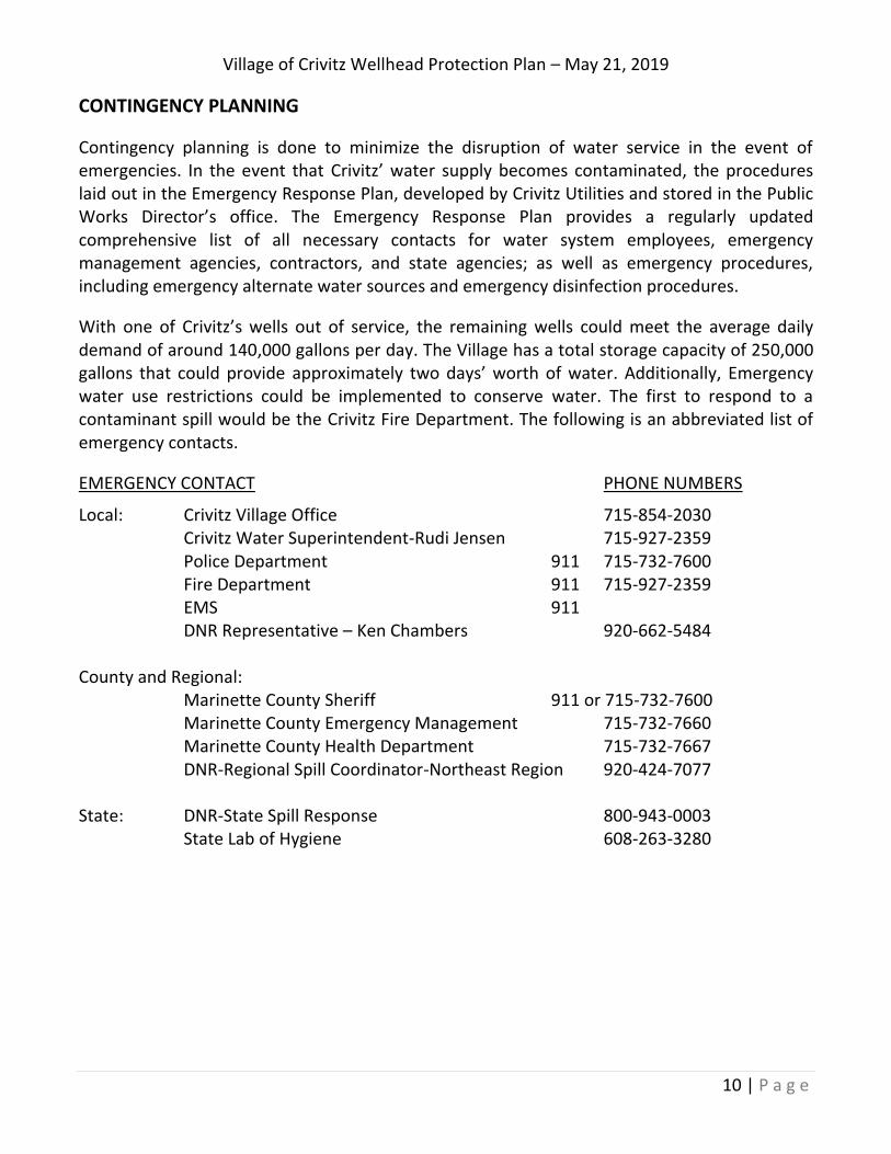
CONTINGENCY PLANNING
Contingency planning is done to minimize the disruption of water service in the event of emergencies. In the event that Crivitz’ water supply becomes contaminated, the procedures laid out in the Emergency Response Plan, developed by Crivitz Utilities and stored in the Public Works Director’s office. The Emergency Response Plan provides a regularly updated comprehensive list of all necessary contacts for water system employees, emergency management agencies, contractors, and state agencies; as well as emergency procedures, including emergency alternate water sources and emergency disinfection procedures.
With one of Crivitz’s wells out of service, the remaining wells could meet the average daily demand of around 140,000 gallons per day. The Village has a total storage capacity of 250,000 gallons that could provide approximately two days’ worth of water. Additionally, Emergency water use restrictions could be implemented to conserve water. The first to respond to a contaminant spill would be the Crivitz Fire Department. The following is an abbreviated list of emergency contacts.
EMERGENCY CONTACT PHONE NUMBERS
Local: Crivitz Village Office 715-854-2030 Crivitz Water Superintendent-Rudi Jensen 715-927-2359 Police Department 911 715-732-7600 Fire Department 911 715-927-2359 EMS 911 DNR Representative – Ken Chambers 920-662-5484 County and Regional: Marinette County Sheriff 911 or 715-732-7600 Marinette County Emergency Management 715-732-7660 Marinette County Health Department 715-732-7667 DNR-Regional Spill Coordinator-Northeast Region 920-424-7077 State: DNR-State Spill Response 800-943-0003 State Lab of Hygiene 608-263-3280
Village of Crivitz Wellhead Protection Plan – May 21, 2019
11 | P a g e
Figure 1 – Village of Crivitz Municipal Well Locations
Village of Crivitz Wellhead Protection Plan – May 21, 2019
12 | P a g e
Figure 2 – Groundwater Flow
Village of Crivitz Wellhead Protection Plan – May 21, 2019
13 | P a g e
Figure 3 – Zone of Contribution, Well #1
Village of Crivitz Wellhead Protection Plan – May 21, 2019
14 | P a g e
Figure 4 –Zone of Contribution, Wells #2 & #3
Village of Crivitz Wellhead Protection Plan – May 21, 2019
15 | P a g e
Figure 5 –Potential Contaminant Sources, Well #1
Village of Crivitz Wellhead Protection Plan – May 21, 2019
16 | P a g e
Figure 6 –Potential Contaminant Sources, Wells #2 & #3
Village of Crivitz Wellhead Protection Plan – May 21, 2019
17 | P a g e
Figure 7 – Wellhead Protection Area, Well #1
Village of Crivitz Wellhead Protection Plan – May 21, 2019
18 | P a g e
Figure 8 – Wellhead Protection Area, Wells #2 & #3
Village of Crivitz Wellhead Protection Plan – May 21, 2019
19 | P a g e
REFERENCES
Bradbury, K.R., Rothschild, E.R., 1985. A computerized technique for estimating the hydraulic conductivity of aquifer from specific capacity data: Ground Water vol. 23, No.2.
Bradbury, K.R., Swanson, K.S., Krohelski, J.T., Fritz, A.K., 1999. Hydrogeology of Dane County, Wisconsin: Wisconsin Geological and Natural History Survey, Open-File Report 1999-04.
Gebert, W.A., Walker, J.F., Kennedy, J.L., 2011. Estimating 1970-99 Average Annual Groundwater Recharge in Wisconsin Using Streamflow Data: U.S. Geological Survey Open-File Report 2009-1210.
Kammerer, P.A., 1995. Ground-Water Flow and Quality in Wisconsin’s Shallow Aquifer System: U.S. Geological Survey, Water-Resources Investigations Report 90-4171.
Kammerer, P.A., 1981. Ground-Water-Quality Atlas of Wisconsin: Wisconsin Geological and Natural History Survey, Information Circular 39.
Kammerer, P.A., Trotta, L.C., Krabbenhoft, D.P., Lidwin, R.A., 1998. Geolgoy, Ground-Water Flow, and Dissolved-Solids Concentrations in Ground Water Along Hydrogeologic Sections Through Wisconsin Aquifers: U.S. Geological Survey, Hydrologic Investigations Atlas HA 731.
Schwartz, R.W., Zhang, H., 2003. Fundamentals of Ground Water: John Wiley & Sons.
Mickelson, D.M., 2003. Glacial and Related Deposits of Langlade County, Wisconsin: Digital Information: Wisconsin Geological and Natural History Survey, Information Circular 52-DI.
Oakes, E.L., Hamilton, L.J., 1973. Water Resources of Wisconsin-Menominee-Oconto-Peshtigo River Basin: U.S. Geological Survey, Hydrologic Investigations Atlas HA-470.
Village of Crivitz Wellhead Protection Plan – May 21, 2019
20 | P a g e
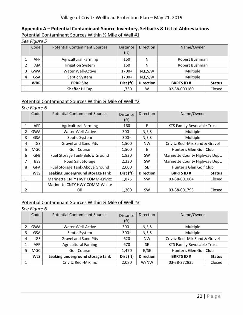
Appendix A – Potential Contaminant Source Inventory, Setbacks & List of Abbreviations Potential Contaminant Sources Within ½ Mile of Well #1 See Figure 5
Code Potential Contaminant Sources Distance (ft)
Direction Name/Owner
1 AFP Agricultural Farming 150 N Robert Bushman
2 AIA Irrigation System 150 N Robert Bushman
3 GWA Water Well-Active 1700+ N,E,S,W Multiple
4 GSA Septic System 1700+ N,E,S,W Multiple
WRP ERRP Site Dist (ft) Direction BRRTS ID # Status
1 Shaffer Hi Cap 1,730 W 02-38-000180 Closed
Potential Contaminant Sources Within ½ Mile of Well #2 See Figure 6
Code Potential Contaminant Sources Distance (ft)
Direction Name/Owner
1 AFP Agricultural Farming 160 E KTS Family Revocable Trust
2 GWA Water Well-Active 300+ N,E,S Multiple
3 GSA Septic System 300+ N,E,S Multiple
4 IGS Gravel and Sand Pits 1,500 NW Crivitz Redi-Mix Sand & Gravel
5 MGC Golf Course 1,500 E Hunter's Glen Golf Club
6 GFB Fuel Storage Tank-Below Ground 1,830 SW Marinette County Highway Dept.
7 BSS Road Salt Storage 2,230 SW Marinette County Highway Dept.
8 GFA Fuel Storage Tank-Above Ground 2,600 SE Hunter's Glen Golf Club
WLS Leaking underground storage tank Dist (ft) Direction BRRTS ID # Status
1 Marinette CNTY HWY COMM-Crivitz 1,875 SW 03-38-001064 Closed
2 Marinette CNTY HWY COMM-Waste
Oil 1,200 SW 03-38-001795 Closed
Potential Contaminant Sources Within ½ Mile of Well #3 See Figure 6
Code Potential Contaminant Sources Distance (ft)
Direction Name/Owner
2 GWA Water Well-Active 300+ N,E,S Multiple
3 GSA Septic System 300+ N,E,S Multiple
4 IGS Gravel and Sand Pits 620 NW Crivitz Redi-Mix Sand & Gravel
1 AFP Agricultural Faming 670 SE KTS Family Revocable Trust
5 MGC Golf Course 1,470 E/SE Hunter's Glen Golf Club
WLS Leaking underground storage tank Dist (ft) Direction BRRTS ID # Status
1 Crivitz Redi-Mix Inc 2,080 W/NW 03-38-272835 Closed
Village of Crivitz Wellhead Protection Plan – May 21, 2019
21 | P a g e
Village of Crivitz Wellhead Protection Plan – May 21, 2019
22 | P a g e
Village of Crivitz Wellhead Protection Plan – May 21, 2019
23 | P a g e
Village of Crivitz Wellhead Protection Plan – May 21, 2019
24 | P a g e
Village of Crivitz Wellhead Protection Plan – May 21, 2019
25 | P a g e
Appendix B – Lithologic Logs and Well Construction Details
Village of Crivitz Wellhead Protection Plan – May 21, 2019
2
Village of Crivitz Wellhead Protection Plan – May 21, 2019
3