Embed Size (px)
Citation preview
PROCEEDINGS, 43rd Workshop on Geothermal Reservoir Engineering
Stanford University, Stanford, California, February 12-14, 2018
SGP-TR-213
1
Wellbore Integrity Assessment with Casing-Based Advanced Sensing
Michael Wilt1*, Evan Um1, Chester Weiss2, Don Vasco1, Petr Petrov1, Greg Newman1, Yuxin Wu1
1Lawrence Berkeley National Lab, Berkeley CA 94720
2Sandia National Laboratories, Albuquerque, NM 87123
Keywords: well integrity, geophysics, infrastructure, electromagnetics, electrostatics, seismics, numerical modeling
ABSTRACT
Wellbore integrity is of paramount importance to subsurface resource extraction, energy storage 1and waste disposal. After installation,
well casing and cement are subject to mechanical stress due to near-well pressure changes and fluid induced corrosion. This is
exacerbated for geothermal wells where produced fluid is at high temperature and corrosive. The current state-of-the-art technologies
for wellbore integrity assessments are an array of cased hole logging tools. Wireline deployed acoustic, electromagnetic and mechanical
tools are all available to inspect steel casing corrosion and casing-cement bond and these tools can provide high-resolution assessment
of borehole conditions. They are intrusive, however, in terms of borehole preparation and interruption to the normal operation of the
wells, and not suitable for high temperature or highly deviated well deployments. In addition, these measurements are performed
infrequently due to high cost, and are therefore incapable of providing frequent data to better predict borehole degradation trajectory,
which can help provide early warning of potential borehole failures.
For this project we are developing a suite of novel, non-invasive, casing based tools for wellbore integrity assessment, combining
fast/low cost screening with higher-precision investigation. Our approach is based on monitoring the response of the casing when
energized at the wellhead, thereby interrogating the casing without well intervention. Lab, field and numerical approaches are used in
our study. During the early stage of the research, we focus on numerical simulations, which have shown the sensitivity of the low
frequency electromagnetic (EM) signals to changes in borehole depths and have successfully tested the concept at a field site with
different length well casings. Initial seismic modeling efforts have also demonstrated our capability to simulate seismic tube wave and
seismic field alterations due to borehole breakage and associated fluid leakage. Further numerical, laboratory and field experiments are
underway for additional technology sensitivity analysis, particularly the transient EM/Seismic reflectometry methods, data acquisition
optimization, and numerical simulation improvements.
1. INTRODUCTION
Wellbore integrity is of paramount importance to subsurface resource extraction, energy storage and waste disposal. After installation,
the casing and cement are subject to mechanical stress due to near-well pressure changes and fluid induced corrosion. This is
exacerbated for geothermal and carbon-capture and storage (CCS) wells where produced water is at high temperature or contains
dissolved CO2 and H2S, which can accelerate corrosion rates. Impaired wellbores could result in reduced productivity, early
abandonment and leakage (e.g. CO2, methane or other hydrocarbons) that can cause significant damages to both humans and the
environment, as witnessed during the recent Aliso Canyon gas leakage events (Conley et. al., 2016) . Recent studies have shown more
than 1 million wells in the US have significant completion degradation and many of these are leaking (Ingraffea et al., 2014).
Effective wellbore integrity monitoring is critical for assessing the borehole state of health, identifying damaged zones for remedial
actions and guiding decision-making. In addition to the deep and often pressurized boreholes that are not easily accessible, technologies
for wellbore integrity monitoring are further challenged with complex subsurface geology, geochemistry and stress conditions that result
in extreme variability of damage rate, pattern, magnitude and depth among different wells. The current state-of-the-art technologies for
wellbore integrity assessments are an array of cased hole logging tools. Wireline deployed acoustic, electromagnetic and mechanical
tools are all available to inspect steel casing corrosion and casing-cement bond and these tools can provide high-resolution assessment
of borehole conditions. They are intrusive, however, in terms of borehole preparation and interruption to the normal operation of the
wells and not suitable for high temperature or highly deviated well deployments. In addition, these measurements are expensive to
obtain and are, thus, performed infrequently which, in most cases, are only when problems with the wells have already occurred. These
limitations render the downhole wireline tools incapable of providing frequent monitoring data in order to better predict borehole
degradation trajectory, which can help provide early warning of potential borehole failures.
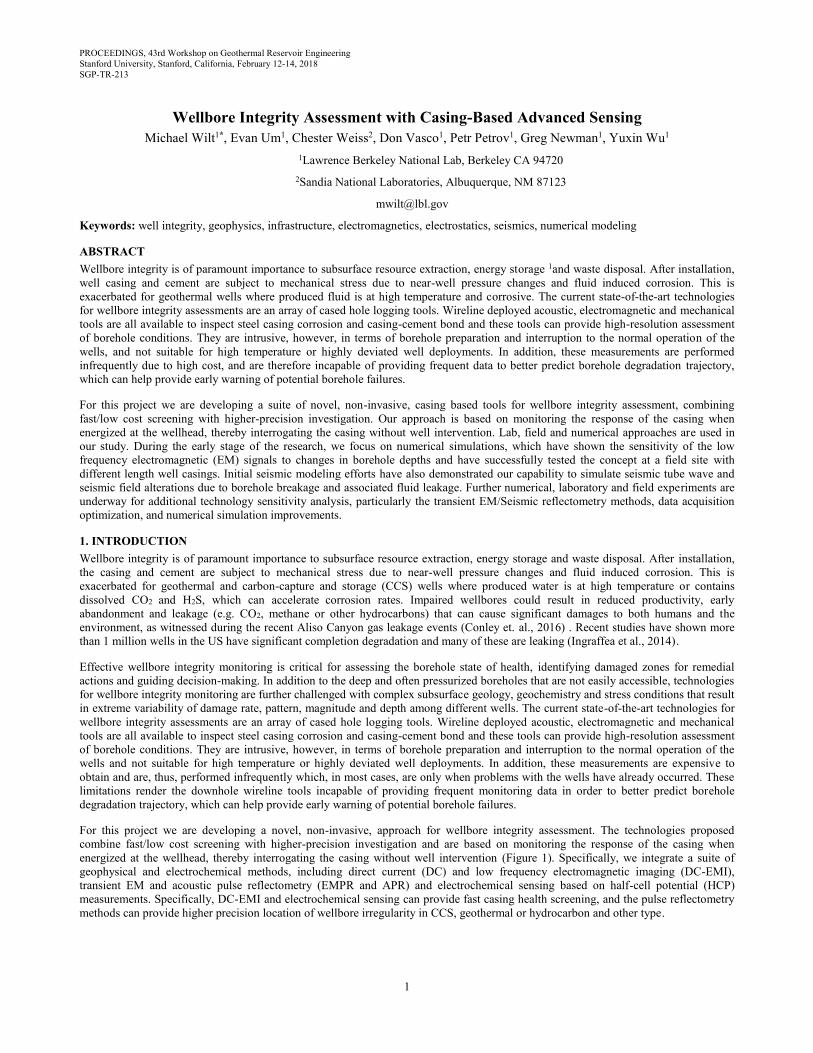
For this project we are developing a novel, non-invasive, approach for wellbore integrity assessment. The technologies proposed
combine fast/low cost screening with higher-precision investigation and are based on monitoring the response of the casing when
energized at the wellhead, thereby interrogating the casing without well intervention (Figure 1). Specifically, we integrate a suite of
geophysical and electrochemical methods, including direct current (DC) and low frequency electromagnetic imaging (DC-EMI),
transient EM and acoustic pulse reflectometry (EMPR and APR) and electrochemical sensing based on half-cell potential (HCP)
measurements. Specifically, DC-EMI and electrochemical sensing can provide fast casing health screening, and the pulse reflectometry
methods can provide higher precision location of wellbore irregularity in CCS, geothermal or hydrocarbon and other type.
Wilt, Um, Weiss, Vasco, Petrov, Newman, and Wu
2
Figure 1: Concepts of the data acquisition system combining low frequency EM with transient EM/Seismic reflectometry and
electrochemical measurements.
2. METHODS
2.1 Low frequency EM method:
An important aspect of this project involves using EM fields, emanating from a wellhead source, to assess the integrity of a well casing
without the requirement of entering the well. The concept utilizes the principle that the majority of the current impressed will remain on
the casing until the string is terminated into the full well depth, or interrupted by broken or corroded casing. Analysis of the resulting
EM profile will therefore be diagnostic on the condition of the well casing. Here we discuss the development and validation of the
modeling codes, the use of these codes for survey design and the application of our system to field site where EM profiles were
measured from wells of different casing depth.
2.1.1 EM Numerical Modeling
Electromagnetic modeling in the presence of steel infrastructures such as cased wells and pipes is difficult because of their hollow
geometry and extreme conductivity contrast. Code EM3D is a 3D finite element code capable of modeling the response of EM source in
an arbitrary 3D earth, which includes metallic well casing and infrastructure. To overcome the modeling challenges associated with steel
infrastructure, we use 3D modeling algorithms with tetrahedral meshes (Um et al., 2017). Tetrahedral meshes allow efficient local
refinements in the computational domain such that fine meshes can be used around arbitrarily complex wells for accurate solution and
coarse meshes elsewhere for efficient solutions. The EM3D code is an important tool in the validation of the EM method, establishing
sensitivity to casing completion and in the design of field surveys.
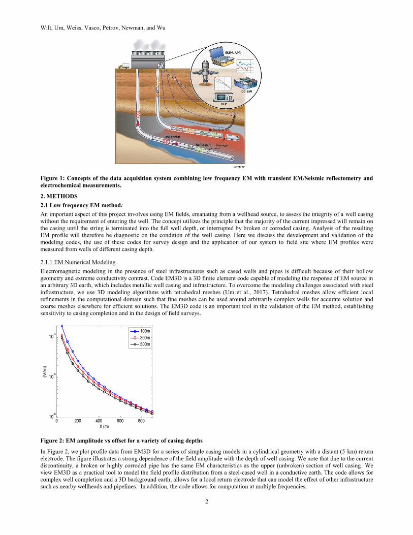
Figure 2: EM amplitude vs offset for a variety of casing depths
In Figure 2, we plot profile data from EM3D for a series of simple casing models in a cylindrical geometry with a distant (5 km) return
electrode. The figure illustrates a strong dependence of the field amplitude with the depth of well casing. We note that due to the current
discontinuity, a broken or highly corroded pipe has the same EM characteristics as the upper (unbroken) section of well casing. We
view EM3D as a practical tool to model the field profile distribution from a steel-cased well in a conductive earth. The code allows for
complex well completion and a 3D background earth, allows for a local return electrode that can model the effect of other infrastructure
such as nearby wellheads and pipelines. In addition, the code allows for computation at multiple frequencies.
Wilt, Um, Weiss, Vasco, Petrov, Newman, and Wu
3
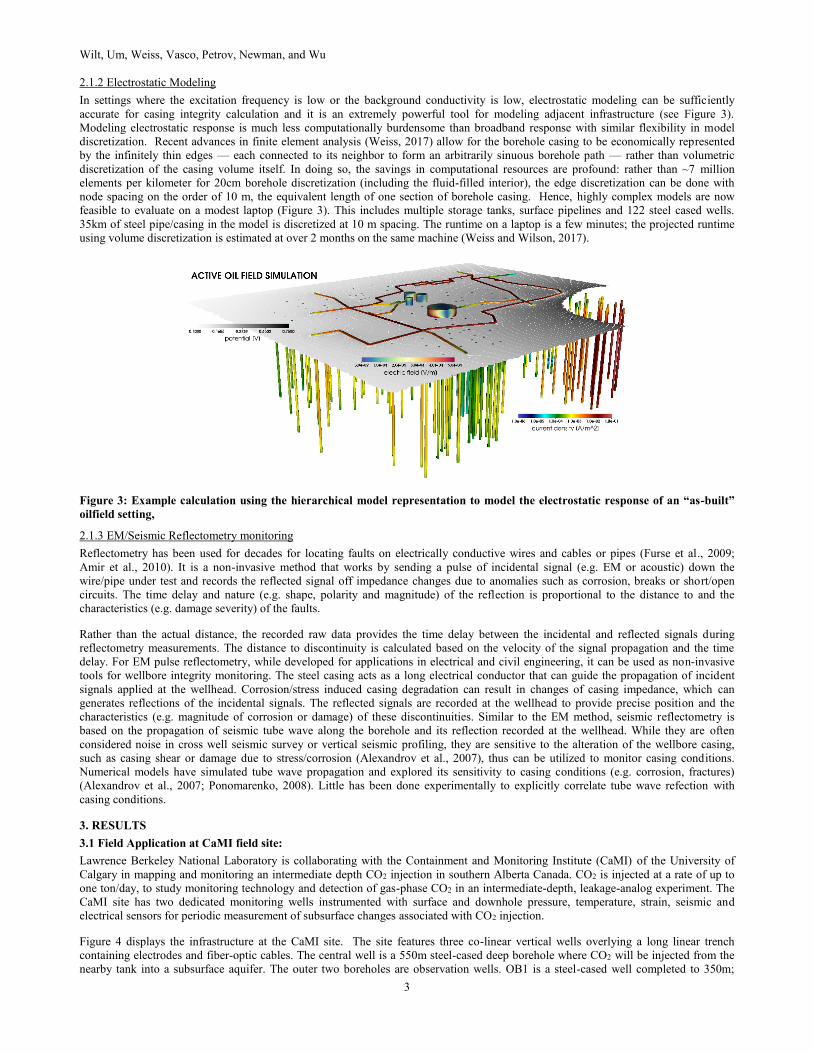
2.1.2 Electrostatic Modeling
In settings where the excitation frequency is low or the background conductivity is low, electrostatic modeling can be sufficiently
accurate for casing integrity calculation and it is an extremely powerful tool for modeling adjacent infrastructure (see Figure 3).
Modeling electrostatic response is much less computationally burdensome than broadband response with similar flexibility in model
discretization. Recent advances in finite element analysis (Weiss, 2017) allow for the borehole casing to be economically represented
by the infinitely thin edges — each connected to its neighbor to form an arbitrarily sinuous borehole path — rather than volumetric
discretization of the casing volume itself. In doing so, the savings in computational resources are profound: rather than ~7 million
elements per kilometer for 20cm borehole discretization (including the fluid-filled interior), the edge discretization can be done with
node spacing on the order of 10 m, the equivalent length of one section of borehole casing. Hence, highly complex models are now
feasible to evaluate on a modest laptop (Figure 3). This includes multiple storage tanks, surface pipelines and 122 steel cased wells.
35km of steel pipe/casing in the model is discretized at 10 m spacing. The runtime on a laptop is a few minutes; the projected runtime
using volume discretization is estimated at over 2 months on the same machine (Weiss and Wilson, 2017).
Figure 3: Example calculation using the hierarchical model representation to model the electrostatic response of an “as-built”
oilfield setting,
2.1.3 EM/Seismic Reflectometry monitoring
Reflectometry has been used for decades for locating faults on electrically conductive wires and cables or pipes (Furse et al., 2009;
Amir et al., 2010). It is a non-invasive method that works by sending a pulse of incidental signal (e.g. EM or acoustic) down the
wire/pipe under test and records the reflected signal off impedance changes due to anomalies such as corrosion, breaks or short/open
circuits. The time delay and nature (e.g. shape, polarity and magnitude) of the reflection is proportional to the distance to and the
characteristics (e.g. damage severity) of the faults.
Rather than the actual distance, the recorded raw data provides the time delay between the incidental and reflected signals during
reflectometry measurements. The distance to discontinuity is calculated based on the velocity of the signal propagation and the time
delay. For EM pulse reflectometry, while developed for applications in electrical and civil engineering, it can be used as non-invasive
tools for wellbore integrity monitoring. The steel casing acts as a long electrical conductor that can guide the propagation of incident
signals applied at the wellhead. Corrosion/stress induced casing degradation can result in changes of casing impedance, which can
generates reflections of the incidental signals. The reflected signals are recorded at the wellhead to provide precise position and the
characteristics (e.g. magnitude of corrosion or damage) of these discontinuities. Similar to the EM method, seismic reflectometry is
based on the propagation of seismic tube wave along the borehole and its reflection recorded at the wellhead. While they are often
considered noise in cross well seismic survey or vertical seismic profiling, they are sensitive to the alteration of the wellbore casing,
such as casing shear or damage due to stress/corrosion (Alexandrov et al., 2007), thus can be utilized to monitor casing conditions.
Numerical models have simulated tube wave propagation and explored its sensitivity to casing conditions (e.g. corrosion, fractures)
(Alexandrov et al., 2007; Ponomarenko, 2008). Little has been done experimentally to explicitly correlate tube wave refection with
casing conditions.
3. RESULTS
3.1 Field Application at CaMI field site:
Lawrence Berkeley National Laboratory is collaborating with the Containment and Monitoring Institute (CaMI) of the University of
Calgary in mapping and monitoring an intermediate depth CO2 injection in southern Alberta Canada. CO2 is injected at a rate of up to
one ton/day, to study monitoring technology and detection of gas-phase CO2 in an intermediate-depth, leakage-analog experiment. The
CaMI site has two dedicated monitoring wells instrumented with surface and downhole pressure, temperature, strain, seismic and
electrical sensors for periodic measurement of subsurface changes associated with CO2 injection.
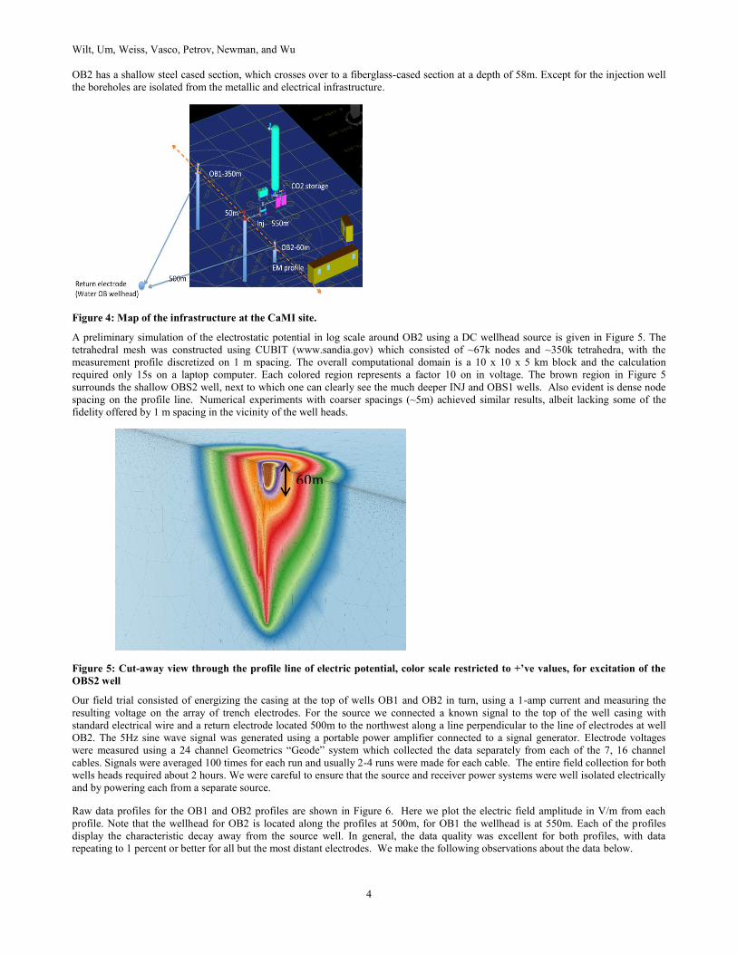
Figure 4 displays the infrastructure at the CaMI site. The site features three co-linear vertical wells overlying a long linear trench
containing electrodes and fiber-optic cables. The central well is a 550m steel-cased deep borehole where CO2 will be injected from the
nearby tank into a subsurface aquifer. The outer two boreholes are observation wells. OB1 is a steel-cased well completed to 350m;
Wilt, Um, Weiss, Vasco, Petrov, Newman, and Wu
4
OB2 has a shallow steel cased section, which crosses over to a fiberglass-cased section at a depth of 58m. Except for the injection well
the boreholes are isolated from the metallic and electrical infrastructure.
Figure 4: Map of the infrastructure at the CaMI site.
A preliminary simulation of the electrostatic potential in log scale around OB2 using a DC wellhead source is given in Figure 5. The
tetrahedral mesh was constructed using CUBIT (www.sandia.gov) which consisted of ~67k nodes and ~350k tetrahedra, with the
measurement profile discretized on 1 m spacing. The overall computational domain is a 10 x 10 x 5 km block and the calculation
required only 15s on a laptop computer. Each colored region represents a factor 10 on in voltage. The brown region in Figure 5
surrounds the shallow OBS2 well, next to which one can clearly see the much deeper INJ and OBS1 wells. Also evident is dense node
spacing on the profile line. Numerical experiments with coarser spacings (~5m) achieved similar results, albeit lacking some of the
fidelity offered by 1 m spacing in the vicinity of the well heads.
Figure 5: Cut-away view through the profile line of electric potential, color scale restricted to +’ve values, for excitation of the
OBS2 well
Our field trial consisted of energizing the casing at the top of wells OB1 and OB2 in turn, using a 1-amp current and measuring the
resulting voltage on the array of trench electrodes. For the source we connected a known signal to the top of the well casing with
standard electrical wire and a return electrode located 500m to the northwest along a line perpendicular to the line of electrodes at well
OB2. The 5Hz sine wave signal was generated using a portable power amplifier connected to a signal generator. Electrode voltages
were measured using a 24 channel Geometrics “Geode” system which collected the data separately from each of the 7, 16 channel
cables. Signals were averaged 100 times for each run and usually 2-4 runs were made for each cable. The entire field collection for both
wells heads required about 2 hours. We were careful to ensure that the source and receiver power systems were well isolated electrically
and by powering each from a separate source.
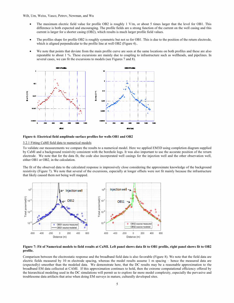
Raw data profiles for the OB1 and OB2 profiles are shown in Figure 6. Here we plot the electric field amplitude in V/m from each
profile. Note that the wellhead for OB2 is located along the profiles at 500m, for OB1 the wellhead is at 550m. Each of the profiles
display the characteristic decay away from the source well. In general, the data quality was excellent for both profiles, with data
repeating to 1 percent or better for all but the most distant electrodes. We make the following observations about the data below.
60m
Wilt, Um, Weiss, Vasco, Petrov, Newman, and Wu
5
The maximum electric field value for profile OB2 is roughly 1 V/m, or about 5 times larger that the level for OB1. This
difference is both expected and encouraging. The profile fields are a strong function of the current on the well casing and this
current is larger for a shorter casing (OB2), which results is much larger profile field values.
The profiles shape for profile OB2 is roughly symmetric but not so for OB1. This is due to the position of the return electrode,
which is aligned perpendicular to the profile line at well OB2 (Figure 4)..
We note that points that deviate from the main profile curve are seen at the same locations on both profiles and these are also
repeatable to about 1 %. These excursions are mainly due to coupling to infrastructure such as wellheads, and pipelines. In
several cases, we can fit the excursions to models (see Figures 7 and 8).
Figure 6: Electrical field amplitude surface profiles for wells OB1 and OB2
3.2.1 Fitting CaMI field data to numerical models
To validate our measurements we compare the results to a numerical model. Here we applied EM3D using completion diagram supplied
by CaMI and a background resistivity consistent with the borehole logs. It was also important to use the accurate position of the return
electrode. We note that for the data fit, the code also incorporated well casings for the injection well and the other observation well,
either OB1 or OB2, in the calculation.
The fit of the observed data to the calculated response is impressively close considering the approximate knowledge of the background
resistivity (Figure 7). We note that several of the excursions, especially at longer offsets were not fit mainly because the infrastructure
that likely caused them not being well mapped.
Figure 7: Fit of Numerical models to field results at CaMI. Left panel shows data fit to OB1 profile, right panel shows fit to OB2
profile.
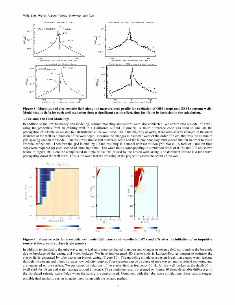
Comparison between the electrostatic response and the broadband field data is also favorable (Figure 8). We note that the field data are
electric fields measured by 10 m electrode spacing, whereas the model results assume 1 m spacing – hence the measured data are
(expectedly) smoother than the modeled data. We demonstrate here, that the DC results may be a reasonable approximation to the
broadband EM data collected at CAMI. If this approximation continues to hold, then the extreme computational efficiency offered by
the hierarchical modeling used in the DC simulations will permit us to explore far more model complexity, especially the pervasive and
troublesome data artifacts that arise when doing EM surveys in mature, culturally developed sites.
Wilt, Um, Weiss, Vasco, Petrov, Newman, and Wu
6
Figure 8: Magnitude of electrostatic field along the measurement profile for excitation of OBS1 (top) and OBS2 (bottom) wells.
Model results (left) for each well excitation show a significant casing effect, thus justifying its inclusion in the calculation.
3.2 Seismic Oil Field Modeling:
In addition to the low frequency EM modeling, seismic modeling simulations were also conducted. We constructed a model of a well
using the properties from an existing well in a California oilfield (Figure 9). A finite difference code was used to simulate the
propagation of seismic waves due to a disturbance at the well head. As in the majority of wells, there were several changes in the outer
diameter of the well as a function of the well depth. Because the changes in diameter were of the order of 5 cm, that was the minimum
grid spacing used in the model. The well was almost 400 meters in depth and the lateral boundary must extend that far in order to avoid
artificial reflections. Therefore the grid is 6000 by 10000, resulting in a model with 60 million grid blocks. A total of 1 million time
steps were required for each second of simulated time. The wave fields corresponding to simulation times of 0.07s and 0.7s are shown
below in Figure 10. Note the complicated multiple reflections caused by the nested well casing. The dominant feature is a tube wave
propagating down the well bore. This is the wave that we are using in the project to assess the health of the well.
Figure 9: Shear velocity for a realistic well model (left panel) and wavefields 0.07 s and 0.7s after the initiation of an impulsive
source at the ground surface (right panels).
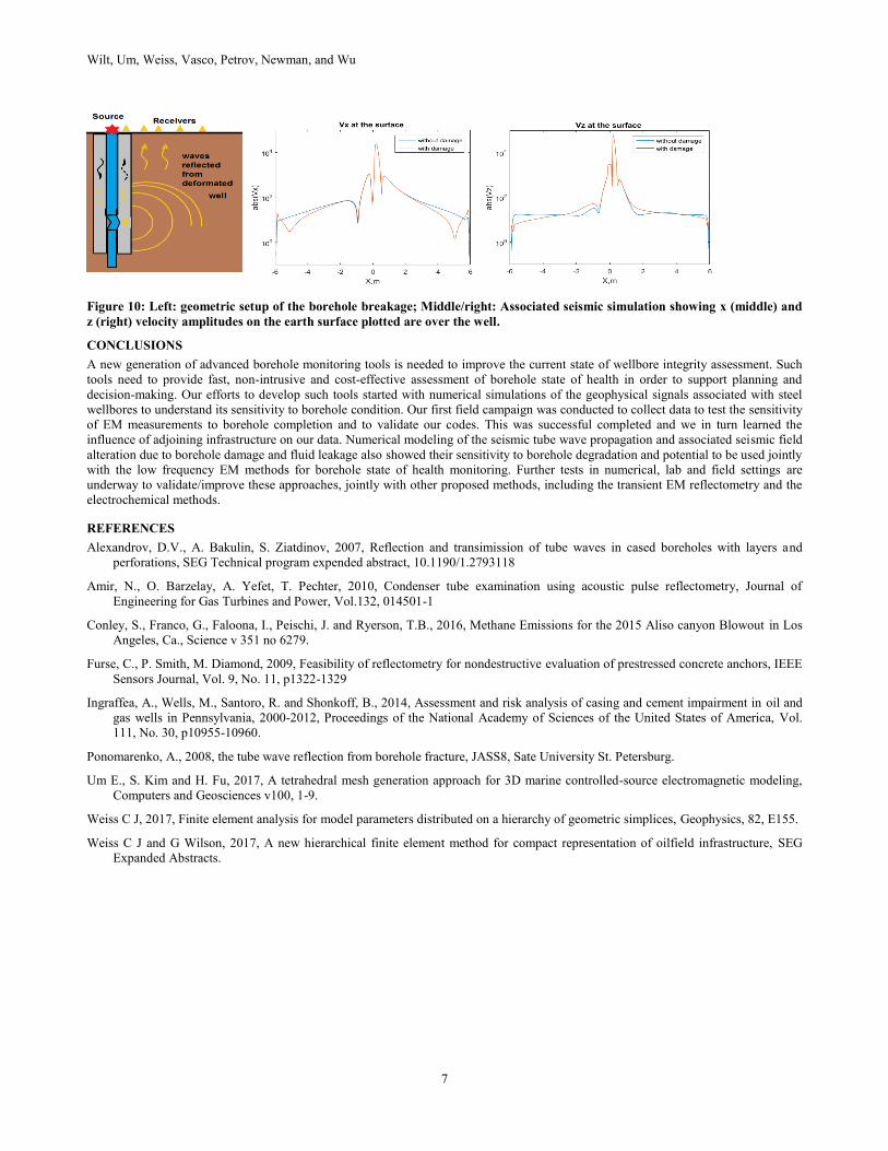
In addition to simulating the tube wave, numerical tests were conducted to understand changes in seismic field surrounding the borehole
due to breakage of the casing and water leakage. We have implemented 3D elastic code in Laplace-Fourier domain to estimate the
elastic fields generated by tube waves on broken casing (Figure 10). The modeling simulates a casing break that causes water leakage
through the cement and thereby creates low velocity regions. These regions can be a source of tube waves, and wavefield scattering and
are registered on the surface. We performed simulations of the elastic field at frequency 50 Hz for the well broken at the depth 35 m
(well shift for 16 cm and water leakage around 2 meters). The simulation results presented on Figure 10 show detectable differences in
the simulated seismic wave fields when the casing is compromised. Combined with the tube wave simulations, these results suggest
possible dual modality casing integrity monitoring with the seismic method.
Wilt, Um, Weiss, Vasco, Petrov, Newman, and Wu
7
Figure 10: Left: geometric setup of the borehole breakage; Middle/right: Associated seismic simulation showing x (middle) and
z (right) velocity amplitudes on the earth surface plotted are over the well.
CONCLUSIONS
A new generation of advanced borehole monitoring tools is needed to improve the current state of wellbore integrity assessment. Such
tools need to provide fast, non-intrusive and cost-effective assessment of borehole state of health in order to support planning and
decision-making. Our efforts to develop such tools started with numerical simulations of the geophysical signals associated with steel
wellbores to understand its sensitivity to borehole condition. Our first field campaign was conducted to collect data to test the sensitivity
of EM measurements to borehole completion and to validate our codes. This was successful completed and we in turn learned the
influence of adjoining infrastructure on our data. Numerical modeling of the seismic tube wave propagation and associated seismic field
alteration due to borehole damage and fluid leakage also showed their sensitivity to borehole degradation and potential to be used jointly
with the low frequency EM methods for borehole state of health monitoring. Further tests in numerical, lab and field settings are
underway to validate/improve these approaches, jointly with other proposed methods, including the transient EM reflectometry and the
electrochemical methods.
REFERENCES
Alexandrov, D.V., A. Bakulin, S. Ziatdinov, 2007, Reflection and transimission of tube waves in cased boreholes with layers and
perforations, SEG Technical program expended abstract, 10.1190/1.2793118
Amir, N., O. Barzelay, A. Yefet, T. Pechter, 2010, Condenser tube examination using acoustic pulse reflectometry, Journal of
Engineering for Gas Turbines and Power, Vol.132, 014501-1
Conley, S., Franco, G., Faloona, I., Peischi, J. and Ryerson, T.B., 2016, Methane Emissions for the 2015 Aliso canyon Blowout in Los
Angeles, Ca., Science v 351 no 6279.
Furse, C., P. Smith, M. Diamond, 2009, Feasibility of reflectometry for nondestructive evaluation of prestressed concrete anchors, IEEE
Sensors Journal, Vol. 9, No. 11, p1322-1329
Ingraffea, A., Wells, M., Santoro, R. and Shonkoff, B., 2014, Assessment and risk analysis of casing and cement impairment in oil and
gas wells in Pennsylvania, 2000-2012, Proceedings of the National Academy of Sciences of the United States of America, Vol.
111, No. 30, p10955-10960.
Ponomarenko, A., 2008, the tube wave reflection from borehole fracture, JASS8, Sate University St. Petersburg.
Um E., S. Kim and H. Fu, 2017, A tetrahedral mesh generation approach for 3D marine controlled-source electromagnetic modeling,
Computers and Geosciences v100, 1-9.
Weiss C J, 2017, Finite element analysis for model parameters distributed on a hierarchy of geometric simplices, Geophysics, 82, E155.
Weiss C J and G Wilson, 2017, A new hierarchical finite element method for compact representation of oilfield infrastructure, SEG
Expanded Abstracts.


![AOI [1]: Charged Wellbore Casing Controlled Source ... Library/Events/2017/carbon-storage... · AOI [1]: Charged Wellbore Casing Controlled Source Electromagnetics (CSC -CSEM) for](https://img.pdfslide.us/doc/110x75/5aa053157f8b9a71178de903/aoi-1-charged-wellbore-casing-controlled-source-libraryevents2017carbon-storageaoi.jpg)