Embed Size (px)
Citation preview

Well-Guard Control™ Pumping Plant Panels
Catalog8940CT9701R7/08
2008Class 8940
IRRIGATION
OIL PRODUCTION
CONTENTS
Description . . . . . . . . . . . . . . . . . . . . . . . . . . . . . . . . . . . . . . . . . . . . . PageSelection Guide . . . . . . . . . . . . . . . . . . . . . . . . . . . . . . . . . . . . . . . . . Page 3Factory Modifications . . . . . . . . . . . . . . . . . . . . . . . . . . . . . . . . . . . . . Page 6Application Data . . . . . . . . . . . . . . . . . . . . . . . . . . . . . . . . . . . . . . . . . Page 8Dimensions. . . . . . . . . . . . . . . . . . . . . . . . . . . . . . . . . . . . . . . . . . . . Page 12
Courtesy of Steven Engineering, Inc.-230 Ryan Way, South San Francisco, CA 94080-6370-Main Office: (650) 588-9200-Outside Local Area: (800) 258-9200-www.stevenengineering.com

© 1997-2008 Schneider ElectricAll Rights Reserved
209/2008
Courtesy of Steven Engineering, Inc.-230 Ryan Way, South San Francisco, CA 94080-6370-Main Office: (650) 588-9200-Outside Local Area: (800) 258-9200-www.stevenengineering.com

Well-Guard Control™ Pump Panels, Full Voltage–Class 8940Irrigation Style Selection Guide
309/2008© 1997-2008 Schneider Electric
All Rights Reserved
Class 8940 Type NP IEC Style Pump Panels, in NEMA Type 3R enclosures, are specifically designed for irrigation applications. All panels are supplied with a visible-blade fused disconnect switch (unless noted). Extra panel space is provided for field installation of auxiliary equipment (refer to page 12 for approximate dimensions).
• Approved for submersible pump applications• Class 10 bimetallic overload relay through 100 hp-480 V, 50 hp–240 V• Adjustable trip current• Includes a Start push button and a Hand-Off-Auto selector switch• Ambient temperture compensated• TeSys™ D and TeSys™ F contactors are used as standard• Sizes closely matched to common motor sizes• All devices are UL Listed and marked “SUITABLE ONLY FOR USE AS SERVICE EQUIPMENT”
Fusible Disconnect Switch Type600 Volts Max. – 3-Pole – 50-60 Hertz
Volts Max. hp Polyphase Coil Voltage k Fuse Clip Amperes q Class 8990 Type c
240
3
240-60220-50
30 NPD2003V035 30 NPE2005V037.5 30 NPE2007V0310 60 NPF2010V0315 60 NPF2015V0320 100 NPG2020V0325 100 NPG2025V0330 100 NPJ2030V0340 200 NPJ2040V0350 200 NPJ2050V03
Above 50 hp, see page 4
480
3480-60440-50
30 NPD4003V06
5 30 NPD4005V06
7.5 30 NPD4007V06
10 30 NPE4010V06
15 30 NPE4015V06
20 60 NPF4020V06
25 60 NPF4025V06
30 60 NPF4030V06
40 100 NPG4040V06
50 100 NPG4050V06
60 100 NPJ4060V06
75 200 NPJ4075V06
100 200 NPJ4100V06
Above 100 hp, see page 4.k Coil voltage code must be specified to order this product. Refer to standard voltage codes listed at left.q Fuse clips are sized for use with dual-element time-delay fuses.
Listed File E152395
Listed File E152395
Coil Voltage Codes
VoltageCode
60 Hz 50 Hz
24 jp . . . V01120 j 110 V02208 j . . . V08240 220 V03. . . 380 V05480 440 V06600 j 550 V07For hp higher than 100, see page 4.p Must be specially
wound for NPJ devices.j Form S (separate
control) required for 24 V, 120 V, 208 V, and 600 V coils.
Courtesy of Steven Engineering, Inc.-230 Ryan Way, South San Francisco, CA 94080-6370-Main Office: (650) 588-9200-Outside Local Area: (800) 258-9200-www.stevenengineering.com

© 1997-2008 Schneider ElectricAll Rights Reserved
Well-Guard Control™ Pump Panels, Full Voltage–Class 8940 Irrigation and Oil Field Style Selection Guide
409/2008
Class 8940 Type NS, SS and XS Pump Panels, in NEMA Type 3R enclosures, are specifically designed for irrigation and oil field applications. All panels are supplied with a visible-blade fused disconnect switch (unless noted). Extra panel space is provided for field installation of auxiliary equipment (refer to page 12 for approximate dimensions).• Type S contactor provided as standard• Approved for submersible pump applications• Class 10 Motor Logic® SSOLR through 200 hp-480 V, 100 hp-240V —Type SS*• Includes a Start push button and a Hand-Off-Auto selector switch• Adjustable trip current• Ambient temperature compensated• All devices are UL Listed and marked “SUITABLE ONLY FOR USE AS SERVICE EQUIPMENT”NOTE: The Class 10 Motor Logic SSOLR (solid-state overload relay) does not protect for phase imbalance; however, it does include a rubber boot dust cover.
3-Pole Polyphase – 600Vac Maximum (50-60 Hz) – Fusible Disconnect Switch Type
NOTE: To substitute an ambient compensated bimetallic overload relay (up to size 4) for the Motor Logic SSOLR, request Form B12 and state motor hp (no charge).
3-Pole Polyphase – 600 Volts AC Maximum (50-60 Hz) – Circuit Breaker
Volts Max. hp Polyphase Coil Voltage j Fuse Clip Amperes q Class 8940 Type c
240
3, 5, 7.5
240-60220-50
30 SSC2007 f10, 15 60 SSD2015 f20, 25, 30 100 SSE2030 f40, 50 200 SSF2050 f75 LAL36250 t XSG2075V03 c100 400 SSG2100100 LAL36350 t XSG2100V03 c200 MAL36700 t XSH2200V03 c250 MAL36800 t XSJ2250V03 c300 MAL361000 t XSJ2300V03 c
480
3, 5, 7.5, 10
480-60440-50
30 SSC4010 f15, 20, 25 60 SSD4025 f30 60 SSD4030 f40, 50 100 SSE4050 f60, 75, 100 200 SSF4100 f150 LAL36250 t XSG4150V06 c200 400 SSG4200200 LAL36350 t XSG4200V06 c300 MAL36500 t XSH4300V06 c350 MAL36600 t XSH4350V06 c400 MAL36700 t XSH4400V06 c500 MAL36800 t XSJ4500V06 c600 MAL361000 t XSJ4600V06 c
t MAG-GARD circuit breaker disconnect supplied.q Fuse clips are sized for use with dual-element time-delay fuses.f Voltage code not required for 240 V or 480 V with 8940SS___ controllers.c Type SSC, SSD, SSE, SSF, SSG, and XSJ panels include the Motor Logic SSOLR and do not require thermal units. Types
XSG and XSH panels include a three-unit overload relay. Thermal units must be ordered separately. See Pages 8-9 for selection information.
Volts Max. hp Polyphase Coil Voltage j Circuit Breaker Class 8940 Type
240
25240-60220-50
FAL36100-18MXSE2025V03
30 XSE2030V0340 KAL36250-26M XSE2040V0350 KAL36250-29M XSE2050V03
480
40
480-60440-50
FAL36100-18MXSE4040V06
50 XSE4050V0660
KAL36250-25MXSE4060V06
75 XSE4075V06100 KAL36250-29M XSE4100V06
j See Page 3 for coil voltage codes.
Listed File E152395
Listed File E152395
Courtesy of Steven Engineering, Inc.-230 Ryan Way, South San Francisco, CA 94080-6370-Main Office: (650) 588-9200-Outside Local Area: (800) 258-9200-www.stevenengineering.com

Well-Guard Control™ Pump Panels, Full Voltage–Class 8940Oil Field Style Selection Guide
509/2008© 1997-2008 Schneider Electric
All Rights Reserved
Class 8940 Type S2 Pump Panels, in NEMA Type 3R enclosures, are specifically designed for Oil Field applications. All panels are supplied with a visible-blade fused disconnect switch or a Mag-Gard® circuit breaker, depending on the Type number. Extra panel space is provided for field installation of auxiliary equipment (refer to page 12 for approximate dimensions).
• Rugged spring latches for easy access without a tool• Side mounted control units for convenient operation• Door retainer available for windy areas (Form G45)• Hand-Off-Auto selector switch• UL Listed for use as Service Equipment for Motors• Extra panel space for additional electrical controls• All devices UL Listed and marked “SUITABLE ONLY FOR USE AS SERVICE EQUIPMENT”NOTE: Overload relays are ambient temperature compensated.
Coil Voltage Codes
600 Volts Max. – 3-Pole – 50-60 Hertz
Volts CoilVoltage t
Max. hpPolyphase
NEMA Size
Fusible Disconnect Type Circuit Breaker Type
Fuse Clip Amperes a
Class 8940 Type Frame Size Class 8940
Type
240
240 @ 60 Hz220 @ 50 Hz
7.5 1 30 WC1S2V03 GJL36030M04 XC1S2V03 10
2 60 WD1S2V03 GJL36050M05 XD1S2V03
15 FAL3610018M XD2S2V03 30 3 100 WE1S2V03 FAL3610018M XE1S2V03 40
4 200 WF1S2V03 KAL3625026M XF1S2V03
50 KAL3625029M XF2S2V03
480
480 @ 60 Hz440 @ 50 Hz
7.51 30 WC3S2V06
GJL36015M03 XC3S2V06 10 GJL36030M04 XC4S2V06 15
2 60 WD3S2V06 GJL36030M04 XD3S2V06
25 GJL36050M05 XD4S2V06 50 3 100 WE3S2V06 FAL3610018M XE3S2V06 75
4 200 WF3S2V06 KAL3625025M XF3S2V06
100 KAL3625029M XF4S2V06 a Fuse clips are sized for use with dual-element time-delay fuses.k Thermal units must be ordered separately.t Coil voltages must be specified to order this product. See coil voltage codes below.
VoltageCode
60 Hz 50 Hz
24 jq — V01
120 j 110 V02
208 j — V08
240 220 V03
— 380 V05
480 440 V06
600 j 550 V07
q 24V coils are not available on Size 4 starters. On Size 1-3, 24V coils are available. Form S must be used.
j Form S (separate control) required for 24 V, 120 V, 208 V, and 600 V coils.
Listed File E152395 CCN NKJH
Listed File E152395 CCN NKJH7
Courtesy of Steven Engineering, Inc.-230 Ryan Way, South San Francisco, CA 94080-6370-Main Office: (650) 588-9200-Outside Local Area: (800) 258-9200-www.stevenengineering.com

© 1997-2008 Schneider ElectricAll Rights Reserved
Well-Guard Control™ Pump Panels, Full Voltage–Class 8940 Factory Modifications
609/2008
Factory Modifications Description Form
Start push button in oil field panel (S2) only A28Substitute Class 10 IEC overload relay – state motor hp B12Control Transformer with Fused Primary:Types: NPD, NPE, NPF, WC, XC, NSC, SSC (50 VA)NPG, NSG, XD, WD, SSD (100 VA)NPJ, NSE, XE, WE, SSE (150 VA)NSF, XF, WF, SSF (300 VA)NSG, XSG, (50 VA and an interposing control relay)
F4T
Door wind latch assembly, factory installed in a standard 8940NPD, NPE, NPF, NPG, NPJ, SSC, SSO, SSE, or SSF panel. G45
Elapsed time meter G97Substitute Class 10 Motor Logic® SSOLR (without phase imbalance protection) H10On delay timer, 0.1 seconds to 1 minute K25Off delay timer, 0.1 seconds to 1 minute K26On delay timer, 1 minute to 3 minute K37Off delay timer, 1 minute to 3 minute K38Backspin timer (time delay on energization) K15Slim panel (Types WC, WD, WF, XC, XD, XF only) L8Short Panel (Types SSE, SSF only) L9Pilot light, red (does not include auxiliary contact) P1Pilot light, green (does not include auxiliary contact) P2Separate Control SAuxiliary Contacts (Specify N.O. or N.C.) X qSpecial UL panel label for modified UL Listed devices on non-standard panels. Requires approval by manufacturing plant. Y1
Lightning Arrester Y1532Phase failure, phase reversal relay with time delay, including undervoltage and overvoltage protection R44 jSubstitute Standard-Trip Melting Alloy Overload Relays (Type S2 only) Y61Substitute Quick-Trip Melting Alloy Overload Relay (Type S2 only) Y611j Requires the use of 120 volt control (Form S or FF4T).q To determine the maximum number of auxiliary contacts which can be added to each Type S device, and for the appropriate X
Form, refer to tables in the Class 8536 section of the current Digest.
Courtesy of Steven Engineering, Inc.-230 Ryan Way, South San Francisco, CA 94080-6370-Main Office: (650) 588-9200-Outside Local Area: (800) 258-9200-www.stevenengineering.com
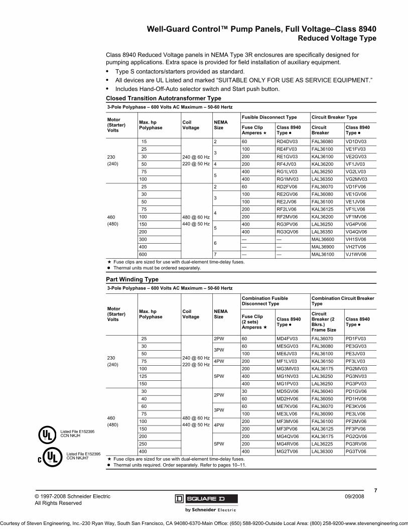
Well-Guard Control™ Pump Panels, Full Voltage–Class 8940Reduced Voltage Type
709/2008© 1997-2008 Schneider Electric
All Rights Reserved
Class 8940 Reduced Voltage panels in NEMA Type 3R enclosures are specifically designed for pumping applications. Extra space is provided for field installation of auxiliary equipment.• Type S contactors/starters provided as standard.• All devices are UL Listed and marked “SUITABLE ONLY FOR USE AS SERVICE EQUIPMENT.”• Includes Hand-Off-Auto selector switch and Start push button.Closed Transition Autotransformer Type
Part Winding Type
3-Pole Polyphase – 600 Volts AC Maximum – 50-60 Hertz
Motor(Starter) Volts
Max. hpPolyphase
CoilVoltage
NEMA Size
Fusible Disconnect Type Circuit Breaker Type
Fuse ClipAmperes a
Class 8940 Type k
Circuit Breaker
Class 8940 Type k
230(240)
15
240 @ 60 Hz220 @ 50 Hz
2 60 RD4DV03 FAL36080 VD1DV03 25
3100 RE4FV03 FAL36100 VE1FV03
30 200 RE1GV03 KAL36100 VE2GV03 50 4 200 RF4JV03 KAL36200 VF1JV03 75
5400 RG1LV03 LAL36250 VG2LV03
100 400 RG1MV03 LAL36350 VG2MV03
460(480)
25
480 @ 60 Hz440 @ 50 Hz
2 60 RD2FV06 FAL36070 VD1FV06 30
3100 RE2GV06 FAL36080 VE1GV06
50 100 RE2JV06 FAL36100 VE1JV06 75
4200 RF2LV06 KAL36125 VF1LV06
100 200 RF2MV06 KAL36200 VF1MV06 150
5400 RG3PV06 LAL36250 VG4PV06
200 400 RG3QV06 LAL36350 VG4QV06 300
6— — MAL36600 VH1SV06
400 — — MAL36900 VH2TV06600 7 — — MAL36100 VJ1WV06
a Fuse clips are sized for use with dual-element time-delay fuses.k Thermal units must be ordered separately.
3-Pole Polyphase – 600 Volts AC Maximum – 50-60 Hertz
Motor(Starter) Volts
Max. hpPolyphase
CoilVoltage
NEMA Size
Combination Fusible Disconnect Type
Combination Circuit Breaker Type
Fuse Clip (2 sets) Amperes a
Class 8940 Type k
Circuit Breaker (2 Bkrs.) Frame Size
Class 8940 Type k
230(240)
25
240 @ 60 Hz220 @ 50 Hz
2PW 60 MD4FV03 FAL36070 PD1FV0330
3PW60 ME5GV03 FAL36080 PE3GV03
50 100 ME6JV03 FAL36100 PE3JV0375 4PW 200 MF1LV03 KAL36150 PF3LV03
1005PW
200 MG3MV03 KAL36175 PG2MV03125 400 MG1NV03 LAL36250 PG3NV03150 400 MG1PV03 LAL36250 PG3PV03
460(480)
30
480 @ 60 Hz440 @ 50 Hz
2PW30 MD5GV06 FAL36040 PD1GV06
40 60 MD2HV06 FAL36050 PD1HV0660
3PW60 ME7KV06 FAL36070 PE3KV06
75 100 ME3LV06 FAL36090 PE3LV06100
4PW200 MF3MV06 FAL36100 PF2MV06
150 200 MF3PV06 KAL36125 PF3PV06200
5PW200 MG4QV06 KAL36175 PG2QV06
250 200 MG4RV06 LAL36225 PG3RV06400 400 MG2TV06 LAL36300 PG3TV06
a Fuse clips are sized for use with dual-element time-delay fuses.k Thermal units required. Order separately. Refer to pages 10–11.
Listed File E152395CCN NKJH
Listed File E152395CCN NKJH7
Courtesy of Steven Engineering, Inc.-230 Ryan Way, South San Francisco, CA 94080-6370-Main Office: (650) 588-9200-Outside Local Area: (800) 258-9200-www.stevenengineering.com

© 1997-2008 Schneider ElectricAll Rights Reserved
Well-Guard Control™ Pump Panels, Full Voltage–Class 8940 Replacement Part Application Data
809/2008
Application Data
Class 8940 Type Disconnect Switch Fuse Base Contactor Overload Relay Overload Relay
Mounting Bracket
NPD2003 40567-200-51t 40566-143-51 LC1D12 LRD16 LAD7B10
NPE2005 40567-200-51t 40566-143-51 LC1D18 LRD21 LAD7B10
NPE2007 40567-200-51t 40566-143-51 LC1D25 LRD22 LAD7B10
NPF2010 40567-200-51t
40566-143-51 (60 A 250 V)40566-144-51 (60 A 600 V)
LC1D32 LRD32 LAD7B10
NPF2015 40567-200-51t
40566-143-51 (60 A 250 V)40566-144-51 (60 A 600 V)
LC1D50 LRD3357 LA7D3064
NPG2020 31301-056-65 31301-059-50 LC1D65 9065TJF40 NA
NPG2025 31301-056-65 31301-059-50 LC1D80 9065TJF40 NA
NPJ2030 31301-056-65 31301-059-50 LC1F115 9065TJF63 NA
NPJ2040 31055-366-51 Included with switch LC1F115 9065TJF63 NA
NPJ2050 31055-366-51 Included with switch LC1F150 9065TJF100 NA
NPD4003 40567-200-51t 40566-143-51 LC1D09 LRD10 LAD7B10
NPD4005 40567-200-51t 40566-143-51 LC1D09 LRD12 LAD7B10
NPD4007 40567-200-51t 40566-143-51 LC1D12 LRD16 LAD7B10
NPE4010 40567-200-51t 40566-143-51 LC1D18 LRD21 LAD7B10
NPE4015 40567-200-51t 40566-143-51 LC1D25 LRD22 LAD7B10
NPF4020 40567-200-51t
40566-143-51 (60 A 250 V)40566-144-51(60 A 600 V)
LC1D32 LRD32 LAD7810
NPF4025 40567-200-51t
40566-143-51 (60 A 250 V)40566-144-51 (60 A 600 V)
LC1D40 LRD3355 LA7D3064
NPF4030 40567-200-51t 40566-144-51 (60 A 250 V) LC1D50 LRD3357 LA7D3064
NPG4040 31301-056-65 31301-059-50 LC1D65 9065TJF40 NA
NPG4050 31301-056-65 31301-059-50 LC1D80 9065TJF40 NA
NPJ4060 31301-056-65 31301-054-50 LC1F115 9065TJF63 NA
NPJ4075 31055-366-51 Included with switch LC1F115 9065TJF63 NA
NPJ4100 31055-366-51 Included with switch LC1F150 9065TJF100 NA
t Includes switch base and operating mechanism. To ensure handle compatibility, part number HM0610F must also be purchased.
NOTE: Two operating mechanisms will be shipped; keep one mechanism as a spare.
Courtesy of Steven Engineering, Inc.-230 Ryan Way, South San Francisco, CA 94080-6370-Main Office: (650) 588-9200-Outside Local Area: (800) 258-9200-www.stevenengineering.com

Well-Guard Control™ Pump Panels, Full Voltage–Class 8940Replacement Part Application Data
909/2008© 1997-2008 Schneider Electric
All Rights Reserved
Application Data
Class 8940 Electrical Interlocks
Class 8940 Type Disconnect Switch Fuse Base Contactor Overload Relay
SSC2007 40567-200-51t 40566-143-51 8502SCO2 31161-547-64
SSD2015 40567-200-51t
40566-143-51 (60 A 250 V)40566-144-51 (60 A 600 V)
8502SDO2 31161-548-83
SSE2030 31301-056-65 31301-059-50 8052SEO2 31161-551-58
SSF2050 31055-366-51 Included with switch 8502SFO2 31161-551-58
SSC4010 40567-200-51t 40566-143-51 8052SCO2 31161-547-64
SSD4025 40567-200-51t
40566-143-51 (60 A 250 V)40566-144-51 (60 A 600 V)
8502SDO2 31161-548-83
SSD4030 40567-200-51t
40566-143-51 (60 A 250 V)40566-144-51 (60 A 600 V)
8502REQ2617G 31161-548-83
SSE4050 31301-056-65 31301-059-50 8502SEO2 31161-551-58
SSF4100 31055-366-51 Included with switch 8502SFO2 31161-553-68
XSG2075 LAL36250 NA 8502SGO2 9065SE06B
SSG2100 9422TG2 NA 31102-668-50 31161-184-74
XSG2100 LAL36350 NA 8502SGO2 9065SE06B
XSH2200 MAL36700 NA 8536SHO2 9065SE06B
XSJ2250 MAL36800 NA 8536JO2 9065SE06B
XSJ2300 MAL361000 NA 8536JO2 9065SE06B
XSG4150 LAL36250 NA 8502SGO2 9065SE06B
SSG4200 9422TG2 NA 31102-668-00 31161-184-74
XSG4200 LAL36350 NA 8502SGO2 9065SE06B
XSH4300 MAL36500 NA 8536SHO2 9065SE06B
XSH4300 MAL36600 NA 8536SHO2 9065SE06B
XSH4400 MAL36700 NA 8536SHO2 9065SE06B
XSJ4500 MAL36800 NA 8536JO2 31161-184-77
XSJ4600 MAL361000 NA 8536JO2 31161-184-77
t Incluses switch base and operating mechanism. To ensure handle compatibility, part number HM0610F must also be purchased.
NOTE: Two operating mechanisms will be shipped; keep one as a spare.
Disconnect Switches Circuit Breakers
Rating StyleSPDT DPDT SPDT DPDT
30A EIK1t EIK2t GJL NA NA60A EIK1t EIK2t FAL 9999R26 9999R27
100A 9999TC10 9999TC20 KAL 9999R26 9999R27200A 9999R39 9999R40 LAL 9999R26 9999R27400A 9999R35 9999R36 MAL 9999R26 9999R27t No class number required.
Courtesy of Steven Engineering, Inc.-230 Ryan Way, South San Francisco, CA 94080-6370-Main Office: (650) 588-9200-Outside Local Area: (800) 258-9200-www.stevenengineering.com

© 1997-2008 Schneider ElectricAll Rights Reserved
Well-Guard Control™ Pump Panels, Full Voltage–Class 8940 Thermal Units
1009/2008
Bimetallic Thermal Unit Selection Tables Based on Motor Full Load Current
Table A - NEMA Size 1 (Table 33)
Table B - NEMA Size 2k (Table 70)
Table C - NEMA Size 3k (Table 37)
t These thermal unit selections are for controllers protected from solar radiation and located in an ambient temperature of 40 oC (104 oF) or less. For overload relays which are not ambient temperature compensated (NEMA Size 3 and 4), thermal units larger than normal can be required under conditions of high ambient temperature and/or solar radiation. Consult your local Square D field office.
k To select thermal units for Type M part winding devices, first divide total motor full load current by 2. Use tables above.
NOTE: This is a partial Thermal Unit Selection Table listing. The complete list can be found in the current Digest.
Table D - NEMA Size 4k (Table 29)
Table E- NEMA Size 5qk (Table 46)
Table F- NEMA Size 6q (Table 47)
Table G- NEMA Size 7
Motor Logic SSOLRAdjustable 270-810 Full Load Current (Ambient Insensitive)
Types WC, XC
Motor Amperes Thermal Unit6.28-6.976.98-7.597.60-7.897.90-8.958.96-10.3
10.4-11.711.8-13.313.4-15.215.3-17.217.3-19.7
19.8-22.422.5-26.0
AR 10.2AR 11.2AR 12.4AR 13.6AR 15.4
AR 17.6AR 20.5AR 23AR 27AR 30
AR 35AR 40
Types MD, PD, RD, VD,WD, XD
Motor Amperes Thermal Unit8.56-9.749.75-11.111.2-12.712.8-14.414.5-16.4
16.5-18.919.0-21.621.7-23.323.4-24.925.0-26.9
27.0-29.129.2-31.331.4-33.533.6-36.937.0-39.1
39.2-40.941.0-45.0
AR 17.6AR 20.5AR 23AR 27AR 30
AR 35AR 40AR 44AR 47AR 51
AR 55AR 60AR 66AR 72AR 79
AR 86AR 94
Types ME, PE, RE, VE, WE, XE
Motor Amperes Thermal Unit27.1-30.030.1-33.233.3-35.735.8-39.439.5-43.4
43.5-46.947.0-51.551.6-57.057.1-62.862.9-69.1
69.2-75.075.1-83.3
E 67E 69E 70E 71E 72
E 73E 74E 76E 77E 78
E 79E 80
Types MF, PF, RF, VF, WF, XF
Motor Amperes Thermal Unit
50.0-55.956.0-60.961.0-65.966.0-69.970.0-75.9
76.0-81.982.0-86.987.0-92.993.0-97.998.0-107.9
108.0-113.9114.0-125.9
E 88E 89E 91E 92E 93
E 94E 96E 97E 98E 99
E 101E 102
u Order Type E thermal units by number from Square D Company, Furnas Electric Company, Batavia, IL or a Furnas Distributor.
Types MG, PG, RG, VG, WG, XG
Motor Amperes Thermal Unit
105-116117-132133-148149-165166-184
185-207208-229230-266
AR 3.28AR 3.62AR 3.98AR 4.37AR 4.80
AR 5.30AR 5.8AR 6.4
q With 300:5 Current Transformer Ratio. Across-the-line and auto-transformer type reduced voltage.
Type VH, XH
Motor Amperes Thermal Unit
146-169170-185186-201202-217218-236
237-253254-279280-311312-353354-396
397-442443-492493-520
AR 1.68AR 1.85AR 2.04AR 2.24AR 2.46
AR 2.71AR 2.98AR 3.28AR 3.62AR 3.98
AR 4.37AR 4.80AR 5.30
q With 800:5 Current Transformer Ratio. Auto-transformer type reduced voltage.
Type
Motor Amperes Thermal Unit
Courtesy of Steven Engineering, Inc.-230 Ryan Way, South San Francisco, CA 94080-6370-Main Office: (650) 588-9200-Outside Local Area: (800) 258-9200-www.stevenengineering.com

Well-Guard Control™ Pump Panels, Full Voltage–Class 8940Thermal Units
1109/2008© 1997-2008 Schneider Electric
All Rights Reserved
Melting Alloy Quick Trip Thermal Unit Selection Tables (Form Y611) Based on Motor Full Load Currentt
Table H- NEMA Size 1 (Table 78)
Table J - NEMA SIZE 3 (Table 80)
Table I - NEMA SIZE 2 (Table 79)
Table K - NEMA SIZE 4 (Table 81)
t These thermal unit selections are for controllers protected from solar radiation and located in an ambient temperature of 40oC (104oF) or less. For overload relays which are not ambient temperature compensated (NEMA Size 3 and 4), thermal units larger than normal can be required under conditions of high ambient temperature and/or solar radiation. Consult your local Square D field office.
NOTE: This is a partial Thermal Unit Selection Table listing. The complete list can be found in the current Digest.
Types WC, XC
Motor Amperes Thermal Unit2.26-2.512.52-2.812.82-3.093.10-3.303.31-3.69
3.70-4.274.28-4.724.73-5.255.26-5.535.54-5.81
5.82-6.146.15-6.446.45-6.816.82-7.197.20-7.59
7.60-7.998.00-8.178.18-8.748.75-9.319.32-9.94
9.95-10.510.6-11.111.2-12.012.0-12.412.5-13.1
13.2-14.314.4-15.315.4-15.916.0-16.917.0-18.3
18.4-19.519.6-20.520.6-21.121.2-22.622.7-23.7
23.8-24.324.4-26.0
FB 3.33FB 3.71FB 4.1FB 4.5FB 4.75
FB 5.3FB 6.1FB 6.75FB 7.45FB 7.8
FB 8.2FB 8.6FB 9.0FB 9.5FB 10
FB 10.6FB 11.2FB 12.1FB 13.1FB 13.9
FB 14.8FB 15.6FB 16.4FB 17.6FB 18.4
FB 19.4FB 21.1FB 22.6FB 23.6FB 24.8
FB 26.7FB 28.3FB 29.6FB 30.5FB 32.6
FB 34.1FB 35
Types WE, XE
Motor Amperes Thermal Unit20.5-21.721.8-23.123.2-24.824.9-26.526.6-28.4
28.5-30.430.5-32.832.9-34.935.0-37.337.4-39.8
39.9-42.542.6-45.845.9-48.248.3-50.650.7-53.1
53.2-56.556.6-59.459.5-63.463.5-71.071.1-78.8
78.9-86.0
FB 26.7FB 28.3FB 29.6FB 30.5FB 32.6
FB 34.1FB 38.3FB 40.2FB 42FB 44
FB 46FB 48FB 50.5FB 52.5FB 55.5
FB 58FB 60FB 63.5FB 69FB 77
FB 84
Types WD, XD
Motor Amperes Thermal Unit4.24-4.694.70-5.215.22-5.495.50-5.745.75-6.07
6.08-6.356.36-6.716.72-7.037.04-7.537.54-7.91
7.92-8.538.54-9.149.15-9.719.72-10.210.3-10.8
10.9-11.511.6-12.312.4-13.013.1-13.914.0-15.115.2-16.116.2-16.917.0-17.918.0-19.419.5-20.7
20.8-21.721.8-22.322.4-23.924.0-25.125.2-25.9
26.0-27.127.2-28.628.7-30.130.2-31.731.8-33.3
33.4-34.534.6-36.536.8-38.538.6-39.940.0-45.0
FB 6.1FB 6.75FB 7.45FB 7.8FB 8.21
FB 8.6FB 9.0FB 9.5 FB 10FB 10.6
FB 11.2FB 12.1FB 13.1FB 13.9FB 14.8
FB 15.6FB 16.4FB 17.6FB 18.4FB 19.4FB 21.1FB 22.6FB 23.6FB 24.8FB 26.7
FB 28.3FB 29.6FB 30.5FB 32.6FB 34.1
FB 35FB 36.6FB 38.3FB 40.2FB 42
FB 44FB 46FB 48FB 50.5FB 52.5
Types WF, XF
Motor Amperes Thermal Unit52.2-55.655.7-58.858.9-62.562.6-66.066.1-70.1
70.2-78.678.7-92.092.1-102103-114115-123
124-133
FB 50.5FB 52.5FB 55.5FB 58FB 60
FB 63.5FB 69FB 77FB 84FB 92
FB 105
Courtesy of Steven Engineering, Inc.-230 Ryan Way, South San Francisco, CA 94080-6370-Main Office: (650) 588-9200-Outside Local Area: (800) 258-9200-www.stevenengineering.com

© 1997-2008 Schneider ElectricAll Rights Reserved
Well-Guard Control™ Pump Panels, Full Voltage–Class 8940 Replacement Part Application Data
1209/2008
Approximate Dimensions
Type Fig. Dim. A B C D E F G H J K ConduitL M
KnockoutV
R S T
NPDNPENPFSSC
1in. 39.05 13.73 6.67 9.70 33.05 37.93 7.00 2.41 3.00 3.00
1-1/22.41
1/2, 3/41-1/4,1-1/2
1/2,3/41.41
mm 992 349 169 246 839 963 178 61 76 76 61 36
NPGNPJSSESSFXSE
2
in. 49 19.15 8.81 10.37 44.07 47.88 7.00 2.17 2.69 3.44 2-1/2 2.57
1/2, 3/41-1/41,2-1/2
1,1-1/41-1/2,2
1.41
mm 1245 486 249 263 1119 1216 178 55 68 87 65 36
HandleSwing
Figure 1 Figure 2
Dual Dimensions:mm
in.
Courtesy of Steven Engineering, Inc.-230 Ryan Way, South San Francisco, CA 94080-6370-Main Office: (650) 588-9200-Outside Local Area: (800) 258-9200-www.stevenengineering.com

Well-Guard Control™ Pump Panels, Full Voltage–Class 8940Replacement Part Application Data
1309/2008© 1997-2008 Schneider Electric
All Rights Reserved
Approximate Dimensions
Type Fig. Dimensions A B C D E F G H J K ConduitL M
KnockoutV
R S T
WC-S2WD-S2XC-S2
1in. 38.50 19.00 7.29 9.39 34.00 37.38 7.00 2.18 2.13 2.13
1-1/22.12
1/2-3/41, 1-1/4,1-1/2
1/2, 3/4—
mm 978 483 185 539 864 949 178 55 54 54 54 —
WE-S2WF-S2XE-S2
1in. 56.50 23.00 8.23 10.33 52.00 55.38 7.00 2.18 2.69 3.44
1/22.68
1/2-3/41, 1-1/4,2, 2-1/2
1, 1-1/41-1/2, 2
1.50
mm 1435 584 209 262 1321 1407 178 55 68 87 68 38
NSGXSG
2in. 74.50 22.00 13.80 17.55 73.00 0.50 14.00 — 0.56 — — — — — — 1.50mm 1892 559 351 446 1854 13 356 — 14 — — — — — — 38
XSH 3in. 82.50 36.00 20.00 23.25 80.00 33.75 16.50 — — — — — — — — —mm 2096 914 508 591 2032 857 419 — — — — — — — — —
XSJ 3in. 92.50 34.00 20.00 23.25 90.00 31.75 16.50 — — — — — — — — —mm 2350 864 508 591 2286 806 419 — — — — — — — — —
Dia. Mtg. Holes Dia. Mtg. Holes
Dia. Mtg. Holes
Figure 1 Figure 2 Figure 3
Dual Dimensions:mm
in.
Courtesy of Steven Engineering, Inc.-230 Ryan Way, South San Francisco, CA 94080-6370-Main Office: (650) 588-9200-Outside Local Area: (800) 258-9200-www.stevenengineering.com

© 1997-2008 Schneider ElectricAll Rights Reserved
Well-Guard Control™ Pump Panels, Full Voltage–Class 8940 Replacement Part Application Data
1409/2008
Part Winding - Reduced Voltage Type
Auto-transformer - Reduced Voltage Type
Type Dimensions t A B C D E F Figure
PDin. 19.00 34.50 12.25 13.00 33.50 0.44
2mm 483 876 311 330 851 11
MDin. 23.00 25.50 10.60 17.00 24.50 0.44
1mm 584 648 269 432 622 11
PEPF
in. 30.00 47.00 13.25 22.00 46.00 0.562
mm 762 1194 337 559 1168 14
MEin. 25.00 52.50 12.13 19.00 51.50 0.44
2mm 635 1334 308 483 1308 11
MFin. 36.00 93.00 19.25 33.75 12.50 0.69
3mm 914 2362 489 857 318 18
PGMG
in. 36.00 73.00 19.25 33.75 12.50 0.693
mm 914 1854 489 857 318 18
PHin. 38.00 93.00 19.25 35.75 12.50 0.69
3mm 965 2362 489 908 318 18
Type Dimensions t A B C D E F Figure
RDVD
in. 25.00 52.50 11.13 19.00 51.50 0.442
mm 635 1334 283 483 1308 11RE, VERF, VF
in. 32.00 72.50 19.25 29.75 12.50 0.683
mm 813 1842 489 756 318 17
RGin. 36.00 93.00 19.25 33.75 12.50 0.69
3mm 914 2362 489 857 318 17
VGin. 32.00 72.50 19.25 29.75 12.50 0.68
3mm 813 1842 489 756 318 17
VHin. 34.00 93.00 23.25 3133.75 16.50 0.69
3mm 864 2362 591 806 419 17
VJ jin. 64.00 93.00 27.25 61.75 17.25 0.81
3✝mm 1626 2362 692 1568 438 21
j Cabinet has double doors
Figure 1 Figure 2 Figure 3
t Dual Dimensions:mm
in.
Courtesy of Steven Engineering, Inc.-230 Ryan Way, South San Francisco, CA 94080-6370-Main Office: (650) 588-9200-Outside Local Area: (800) 258-9200-www.stevenengineering.com
Well-Guard Control™Replacement Part Application Data
1509/2008© 1997-2008 Schneider Electric
All Rights Reserved
Courtesy of Steven Engineering, Inc.-230 Ryan Way, South San Francisco, CA 94080-6370-Main Office: (650) 588-9200-Outside Local Area: (800) 258-9200-www.stevenengineering.com
8940CT9701R7/08 © 1997-2008 Schneider Electric All Rights Reserved Replaces 8940CT9701, December 1997
09/2008
Schneider Electric USA8001 Knightdale Blvd.Knightdale, NC 275451-888-Square D1-888-778-2733www.schneider-electric.us
Courtesy of Steven Engineering, Inc.-230 Ryan Way, South San Francisco, CA 94080-6370-Main Office: (650) 588-9200-Outside Local Area: (800) 258-9200-www.stevenengineering.com


![Biomass Auto Guard Ado] Auto Guard Ado]](https://img.pdfslide.us/doc/110x75/577d2a201a28ab4e1ea8b9ec/biomass-auto-guard-ado-auto-guard-ado.jpg)