Embed Size (px)
Citation preview

Proceedings World Geothermal Congress 2010 Bali, Indonesia, 25-29 April 2010
1
Well design and drilling plans of the Iceland Deep Drilling Project (IDDP)
Sverrir Thorhallsson1, Bjarni Palsson2, Sveinbjörn Hólmgeirsson2, Kristinn Ingason3, Matthías Matthíasson3, Hinrik Árni Bóasson3, Hannes Sverrisson3
1Iceland GeoSurvey (ISOR) (Iceland), 2Landsvirkjun Power (Iceland), 3Mannvit Consulting Engineers (Iceland)
Iceland GeoSurvey, Grensasvegur 9, 108 Reykjavik, Iceland
Keywords: Iceland Deep Drilling, well design, supercritical steam
ABSTRACT
The Iceland Deep Drilling Projects (IDDP) aim is to drill to 4-5 km to investigate the roots of geothermal systems. One question is whether it is technically and economically feasible to extract energy and chemicals where the temperature and pressure may be above the critical point which for fresh water is 374.15°C and 22.12 MPa. Such wells are planned to be drilled at three geothermal sites: Krafla (Landsvirkjun), Hellisheidi (Reykjavik Energy) and Reykjanes (HS Orka). Design and planning of the drilling project was given to the IDDP Drilling Technique Group. Several well designs and drilling scenarios were evaluated to meet the goals of the industrial sponsors and science funds. The scientist wanted to get as much core as possible during the drilling and the power companies for the well to be of large enough diameter for flow testing. Initial plans were for continuous coring below 2400 m with a hybrid coring system that would drill a 4" hole with a HQ wireline core barrel. The final decision was to abandon continuous coring and drill a wider hole and take only spot cores. The final section 3400-4500 m is a 8-1/2" hole where 10 m long 4" diameter spot cores will be taken. The IDDP well is deeper, wider and hotter than have been drilled to date in Iceland. By circulating large quantities of cold water during drilling it is hoped that the temperature inside the well can be maintained below 250°C allowing tri-cone bits to work and not require special materials. A modified core barrel was built to allow high water flows for improved cooling. Drilling mud will be used in drilling to 2400 m but water below that depth. Mud motors will be used to the same depth for improved rate of penetration. The wellhead has been designed for a maximum temperature of 500°C and pressure of 19.5 MPa. The well will have five cemented casing strings, all run from surface, 32" to 80 m, 24-1/2" to 300 m, 18-5/8" to 800 m, 13-5/8" and 13-3/8" to 2400 m and 9-5/8" to 3500 m. The open hole interval 3500-4500 m will have a 7" slotted liner. One of the main challenges is to successfully cement such long casing strings. Stage cementing was selected for the casings to 2400 m and 3500 m. Then the first stage is inner-string cementing to bottom and the second stage is by cementing through ports in the stage collar. Thick walled casing of API K-55 grade steel is selected, same steel as for conventional geothermal wells, except for the top 300 m of the anchor casing where API T-95 is used due to its creep resistance. The casing connections are Hydril/Tenaris 563 for the 13 5/8" and 13 3/8" anchor and 9 5/8" production casing. Wellhead and valves are of ANSI pressure Class 2500. The valves and expansion spool
internal surfaces have weld overlays of stainless and hard facing to protect against eventual acid gases and erosion. The drilling cost of an IDDP well to 4500 m is estimated to be 20 million US$. Several papers at this conference describe the Krafla IDDP-1 well drilled in 2008-2009 which reached 2100 m instead of the target 4500 m as it intersected magma.
1. INTRODUCTION
The first task of the IDDP in 2000 was to set up three working groups for: science SG, drilling technique DT and fluid handling and evaluation FHE. International support was sought and in 2001 ICDP (International Continental Scientific Drilling Program) provided funds to organize the scientific program. A start-up meeting was held in Reykjavík in June 2001, and two workshops were held at Nesjavellir in 2002. In March the workshop on drilling of the well was held with 64 participants. The main issue was to define the drilling targets to be explored from both industrial and scientific viewpoints and to review the possible well designs and coring techniques. The requirements of the scientific program for cores, fluids and downhole measurements were identified. Also the desires of the industrial sponsors for a well that could be flow-tested had to be considered in the design. The concept of a removable inner liner reaching the producing aquifer was introduced by the FHE group. The “pipe” is to protect the well casing and to allow inspection of corrosion and scaling. Four options were identified for adding science coring in two different sizes of production wells. Finally there were discussions on whether drilling into temperatures and pressures that have not been penetrated by drilling is technically feasible. The IDDP SAGA report No. 2, March 2002 describes the outcome of the workshop WS I (IDDP, March 2002. In October the same year a similar workshop WS II focused on the IDDP science (IDDP, October 2002). From information presented at these workshops and discussions the DT group developed the criteria for the design of the well, which were:
• The well would be a vertical, 4-5 km depth. • The design would aim for a “dual purpose” well. It
would maximize the amount of scientific information that could be obtained on supercritical phenomena in an ocean rift setting. It would also fulfill the wishes of the industrial partners for information on the economic potential for power generation.
• The industrial partners would pay for the drilling and domestic and international financial grants would be sought for coring and add-on science.
Thorhallsson et al.
2
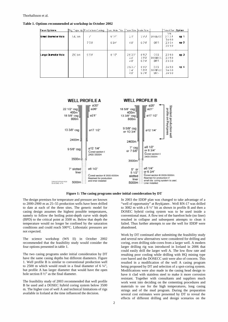
Table 1. Options recommended at workshop in October 2002
Figure 1: The casing programs under initial consideration by DT
The design premises for temperature and pressure are known to 2000-2900 m as 25–55 production wells have been drilled to date at each of the three sites. The generic model for casing design assumes the highest possible temperatures, namely to follow the boiling point-depth curve with depth (BPD) to the critical point at 3500 m. Below that depth the temperature would no longer be confined by the saturation conditions and could reach 500°C. Lithostatic pressures are not expected.
The science workshop (WS II) in October 2002 recommended that the feasibility study would consider the four options presented in table 1.
The two casing programs under initial consideration by DT have the same casing depths but different diameters. Figure 1. Well profile B is similar to conventional production well to 2500 m which would result in a final diameter of 6 ¼”, but profile A has larger diameter that would have the open hole section 8 ½” as the final diameter.
The feasibility study of 2003 recommended that well profile B be used and a DOSEC hybrid coring system below 3500 m. The higher cost of well A and technical limitations of rigs available in Iceland at the time influenced the decision.
In 2003 the IDDP plan was changed to take advantage of a “well of opportunity” at Reykjanes . Well RN-17 was drilled to 3082 m with a 8 ½" bit as shown in profile B and then a DOSEC hybrid coring system was to be used inside a conventional mast. A flow test of the barefoot hole (no liner) resulted in collapse and subsequent attempts to clean it failed. Thus further attempts to use the well for IDDP were abandoned.
Work by DT continued after submitting the feasibility study and several new alternatives were considered for drilling and coring, even drilling side-cores from a larger well. A modern larger drilling rig was introduced in Iceland in 2006 that could easily drill the larger well A. The low flow rate and resulting poor cooling while drilling with HQ mining type core barrel and the DOSECC unit were also of concern. This resulted in a modification of the well A casing program being proposed by DT and selection of a spot-coring system. Modifications were also made in the casing head design to have it clad with stainless steel to make it more corrosion resistant. Together with consultants and suppliers much work went into deciding on the cementing procedures and materials to use for the high temperatures, long casing strings and of the mud program. During the preparation several cost estimates were presented by DT to reveal the effects of different drilling and design scenarios on the
Thorhallsson et al.
3
overall cost and on the cost split between “drilling” and “science”.
Once a decision was reached by IDDP in 2007 to drill the first well (IDDP-1) at Krafla, DT finalized the well design, the drilling program, and prepared the bidding documents for the drilling works and purchase of materials. Iceland as a member of EEA (European Economic Area) has adopted the European Union regulations and thus Landsvirkjun went out for European public procurement for IDDP-1. The drilling program included information on all materials, detailed instructions on specific tasks, health and safety (HSE) and risk assessment for the drilling and coring operations.
2. DESIGN PREMISES
One of the design premises to be established for the well is temperatures and pressures at depth. This affects the selection of the number and depth of casing strings, casing strength and materials, mud and cementing program, bottom hole assembly and logging program, just to mention the main ones. The temperature and pressure (T&P) premises are required for the following cases:
• The static reservoir T&P, the undisturbed conditions at depth.
• Well flowing T&P, dynamic profile. • Predictions of circulation temperatures for each section
of the well at different rig pump flow rates during drilling.
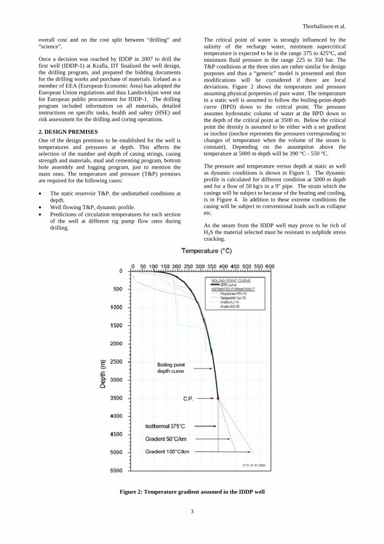
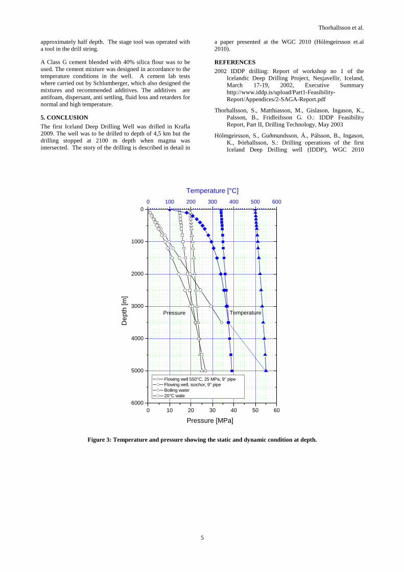
The critical point of water is strongly influenced by the salinity of the recharge water, minimum supercritical temperature is expected to be in the range 375 to 425°C, and minimum fluid pressure in the range 225 to 350 bar. The T&P conditions at the three sites are rather similar for design purposes and thus a “generic” model is presented and then modifications will be considered if there are local deviations. Figure 2 shows the temperature and pressure assuming physical properties of pure water. The temperature in a static well is assumed to follow the boiling-point-depth curve (BPD) down to the critical point. The pressure assumes hydrostatic column of water at the BPD down to the depth of the critical point at 3500 m. Below the critical point the density is assumed to be either with a set gradient or isochor (isochor represents the pressures corresponding to changes of temperature when the volume of the steam is constant). Depending on the assumption above the temperature at 5000 m depth will be 390 °C - 550 °C.
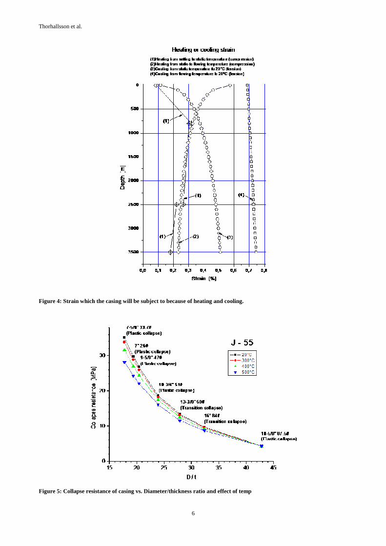
The pressure and temperature versus depth at static as well as dynamic conditions is shown in Figure 3. The dynamic profile is calculated for different condition at 5000 m depth and for a flow of 50 kg/s in a 9" pipe. The strain which the casings will be subject to because of the heating and cooling, is in Figure 4. In addition to these extreme conditions the casing will be subject to conventional loads such as collapse etc.
As the steam from the IDDP well may prove to be rich of H2S the material selected must be resistant to sulphide stress cracking.
Figure 2: Temperature gradient assumed in the IDDP well
Thorhallsson et al.
4
3. CASING DESIGN
The final decision on the well design was to drill a large diameter well with five cemented casings strings and the final diameter of the open hole would be 8 ½". This would allow existing drilling tools to be used and the fluid circulation would be high enough for adequate cooling and control of the well. A modified oilfield core barrel of 4" x 8 ½" would be used to collect spot cores. The casing program is similar to type A described earlier, but the three first casings above 800 m were changed to improve their strength. Near surface the thickness of the anchor casing is 44 mm. For the designing of the casing program the following three standards were used:
• API for conventional conditions. • ASME Boiler and Pressure Vessel Code for creep and
rupture design. • New Zealand NZS 2403 for guidance of conditions.
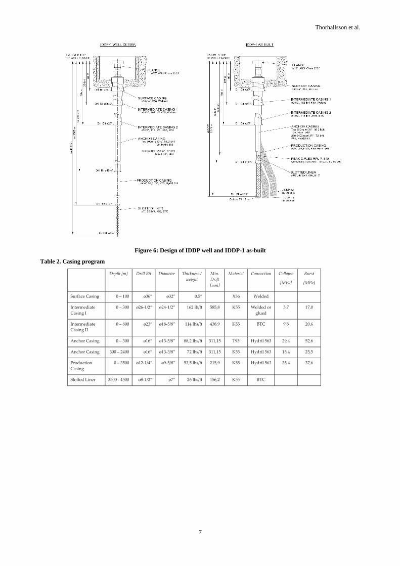
The top part of the anchor casing is designed for creep and rupture conditions and the rest of casing, assumed to be firmly cemented, must be able to withstand the strain presented in Figure 4 as well as conventional conditions such as collapse etc. The effects of temperature on the collapse resistance of the casings are shown in Figure 5.
For the casings which are assumed to be firmly cemented the material selection is conventional API casing steel grade K-55 with a specified maximum hardness of 22 HRC. The yield strain of K-55 is higher than other conventional casing grades and is less susceptible to cracking.
The top part of the anchor casing will not be firmly cemented and must withstand the internal pressure and temperature expected at the wellhead. Therefore the top 300 m of the anchor casing is made of grade API T-95, which has the creep resistance needed.
3.1 Casing Connections
Buttress thread couplings are most commonly used in Iceland as casing connections in high temperature geothermal wells. Buttress has a high tensile strength whereas its compressive strength is a good deal lower. Its ability to withstand the compressive stresses set up by the thermal expansion of cement-encased casings is therefore less good. Indications are that buttress connections are susceptible to leaking when the temperature exceeds 200°C.
Several casing manufacturers have developed a coupling where the pipe end butts against a steel shoulder (Premium connection). Examples of these are the “Antares”, “Hydril” and “GeoConn” connections.
All three connections have good sealing properties, but the Antares connection is, however, more expansion sensitive than the other types.
GeoConn combines standard buttress thread and a coupling. The threaded casing pipe ends are planed and over-tightened to provide a seal. This type of connection has been successfully tested with 2500 psi (17,2 MPa) internal pressure, 392°C temperature, and a corresponding compressive load.
Hydril currently manufactures two types of connections; one where the casing pipe ends are threaded to provide pseudo couplings, and another with standard coupling and threaded ends. The “Hydril 500” type threads have a cross-section shape (called a “Wedge Thread” shape) reminiscent of a dovetail cross-section. According to the manufacturer these
threads withstand an axial load, both in tension and compression, that exceeds the load capacity of the casing itself. A test analogous to thermal expansion of cement encased casing from 20°C to 343°C was carried out on a connection using this type of thread with very good results. Thus Hydirl 563 connections were chosen for the anchor and production casing. The buttress thread connections is however adequed for the liner.
The casing program is shown in Figure 6 and in Table 2.
3.2 Wellhead Design
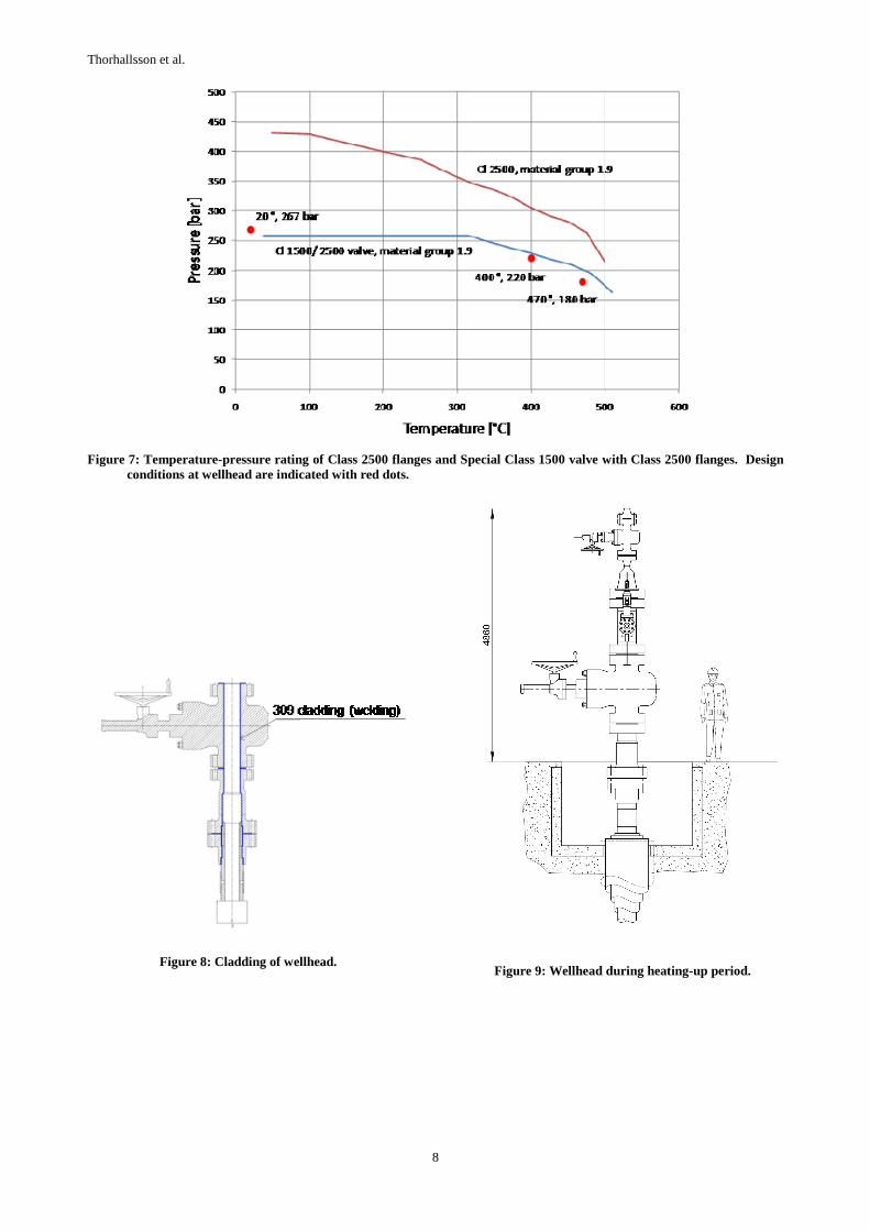
The wellhead consists of a master valve of the expanding gate type, an expansion spool and pack-off and a casing head. Figure 7 shows the expected conditions at the wellhead. Even though supercritical fluid may be encountered at depth this diagram indicates that at surface the steam would be superheated due to loss of pressure traveling up the hole. The wellhead is designed for a maximum temperature of 470°C and pressure of 18 MPa flowing and a pressure of 22 MPa shut-in. The pressure class is ANSI 2500 for all wellhead components, except for the master valve which has a ANSI Special Class 1500 body but ANSI Class 2500 flanges, the strongest that was available for this bore size. There is no kill-line below the master valve as experience in Iceland has shown to require maintenance so it is positioned above the master valve and set blow an ANSI Special Class 1500 operating valve. The wellhead is clad with weld overlay of stainless steel to improve its corrosion resistance as shown in Figure 8. This modification was made after the order was placed when well KJ-36 and other wells in Krafla showed slotted liner damages due to HCl dew-point corrosion. Figure 9 shows the wellhead design and the extra valves installed during heating up phase. The operating valve will be installed before flow testing starts.
4. DRILLING PROGRAM
During drilling the wellhead consist of the rigs blow-out preventers (BOP) sitting on top of the installed master valve. There are many inlets on the BOP stack to pump cold water through. These are conventional BOP´s rated API 5000 class and have parts of rubber seals that cannot take high temperatures for long in case of a blow-out. The BOP includes pipe rams, share rams and blind rams so that in emergencies the drill string can be cut and dropped and the master valve closed.
The well is to be drilled with conventional tri-cone bits that have a proven record in drilling the same fields. The difference is larger diameters and greater depths. The large diameter calls for the use of bentonite drilling mud to 2400 m. Extra mud-cooling capacity by use of cooling tower is required. Below 2400 m water was to be used as drilling fluid. To increase the rate of penetration mud motors were specified for use in part of the well.
In order to reach the planned casing depths of the well it was considered important to limit the fluid losses. The policy for loss of circulation was aimed at sealing loss zones when they were found and depending on the depth losses greater than 5 – 10 l/s were to be cemented.
The intermediate casings were cemented using an inner-string method. The anchor casing and the production casing, however, were cemented in two stages. It was planned to use stage tools. This first stage was cemented with the inner-string method and the second stage through a drill string and a stage tool which was installed in the casing at
Thorhallsson et al.
5
approximately half depth. The stage tool was operated with a tool in the drill string.
A Class G cement blended with 40% silica flour was to be used. The cement mixture was designed in accordance to the temperature conditions in the well. A cement lab tests where carried out by Schlumberger, which also designed the mixtures and recommended additives. The additives are antifoam, dispersant, anti settling, fluid loss and retarders for normal and high temperature.
5. CONCLUSION
The first Iceland Deep Drilling Well was drilled in Krafla 2009. The well was to be drilled to depth of 4,5 km but the drilling stopped at 2100 m depth when magma was intersected. The story of the drilling is described in detail in
a paper presented at the WGC 2010 (Hólmgeirsson et.al 2010).
REFERENCES
2002 IDDP drilling: Report of workshop no 1 of the Icelandic Deep Drilling Project, Nesjavellir, Iceland, March 17-19, 2002, Executive Summary http://www.iddp.is/upload/Part1-Feasibility-Report/Appendices/2-SAGA-Report.pdf
Thorhallsson, S., Matthiasson, M., Gislason, Ingason, K., Palsson, B., Fridleifsson G. O.: IDDP Feasibility Report, Part II, Drilling Technology, May 2003
Hólmgeirsson, S., Guðmundsson, Á., Pálsson, B., Ingason, K., Þórhallsson, S.: Drilling operations of the first Iceland Deep Drilling well (IDDP), WGC 2010
6000
5000
4000
3000
2000
1000
0
0 10 20 30 40 50 60
Flowing well 550°C, 25 MPa, 9" pipe Flowing well, isochor, 9" pipe Boiling water 20°C wate
Dep
th [m
]
Pressure [MPa]
Pressure Temperature
0 100 200 300 400 500 600
Temperature [°C]
Figure 3: Temperature and pressure showing the static and dynamic condition at depth.
Thorhallsson et al.
6
Figure 4: Strain which the casing will be subject to because of heating and cooling.
Figure 5: Collapse resistance of casing vs. Diameter/thickness ratio and effect of temp
Thorhallsson et al.
7
Figure 6: Design of IDDP well and IDDP-1 as-built
Table 2. Casing program
Depth [m] Drill Bit Diameter Thickness / weight
Min. Drift [mm]
Material Connection Collapse
[MPa]
Burst
[MPa]
Surface Casing 0 – 100 ø36” ø32” 0,5” X56 Welded
Intermediate Casing I
0 – 300 ø26-1/2” ø24-1/2” 162 lb/ft 585,8 K55 Welded or glued
5,7 17,0
Intermediate Casing II
0 – 800 ø23” ø18-5/8” 114 lbs/ft 438,9 K55 BTC 9,8 20,6
Anchor Casing 0 – 300 ø16” ø13-5/8” 88,2 lbs/ft 311,15 T95 Hydril 563 29,4 52,6
Anchor Casing 300 – 2400 ø16” ø13-3/8” 72 lbs/ft 311,15 K55 Hydril 563 15,4 25,5
Production Casing
0 – 3500 ø12-1/4” ø9-5/8” 53,5 lbs/ft 215,9 K55 Hydril 563 35,4 37,6
Slotted Liner 3500 - 4500 ø8-1/2” ø7” 26 lbs/ft 156,2 K55 BTC
Thorhallsson et al.
8
Figure 7: Temperature-pressure rating of Class 2500 flanges and Special Class 1500 valve with Class 2500 flanges. Design conditions at wellhead are indicated with red dots.
Figure 8: Cladding of wellhead.
Figure 9: Wellhead during heating-up period.