Embed Size (px)
Citation preview
1
TACK WELDING WORK STANDERD (BASED ON TES 225-012)
1) BEAD LENGTH AND PITCH: - The standard tack welding bead
and pitch is as shown in the table below –
PLATE THICKNESS (in mm) BEAD LENGTH (in mm) PITCH (in mm)
4 10 250
4 28 40 500
28 70 800
NOTE: The diameter of the tack-welding rod normally shall be less then
4mm However when tack welding is used to hang, the bead length shall
be placed so that no safety problems exist.
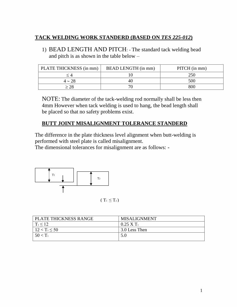
BUTT JOINT MISALIGNMENT TOLERANCE STANDERD
The difference in the plate thickness level alignment when butt-welding is
performed with steel plate is called misalignment.
The dimensional tolerances for misalignment are as follows: -
PLATE THICKNESS RANGE MISALIGNMENT
T1 ≤ 12 0.25 X T1
12 < T1 ≤ 50 3.0 Less Then
50 < T1 5.0
T1 T2
( T1 ≤ T2 )
2
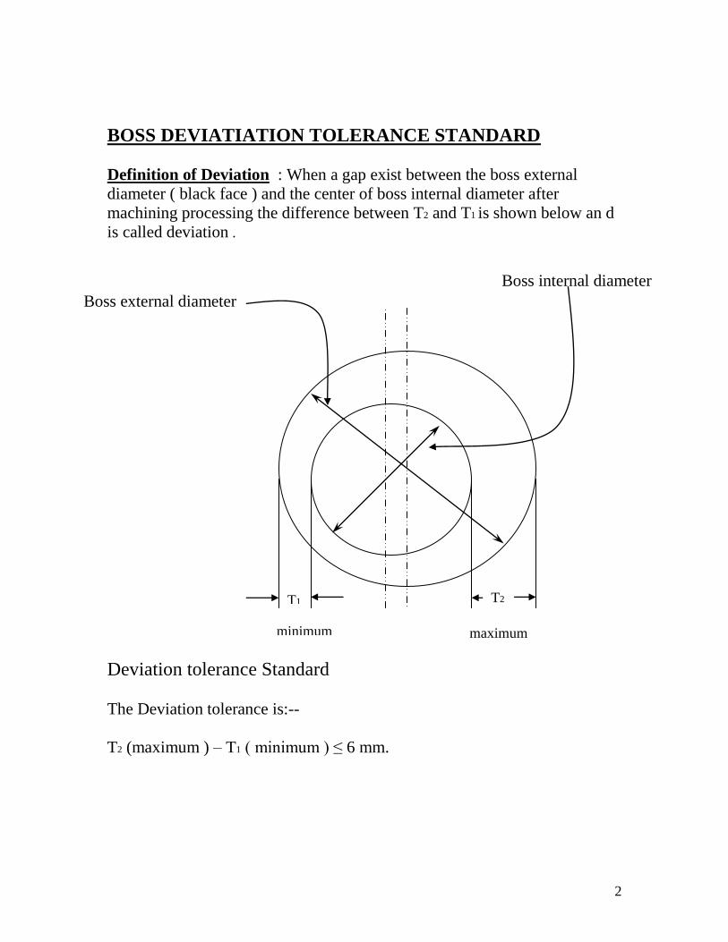
BOSS DEVIATIATION TOLERANCE STANDARD
Definition of Deviation : When a gap exist between the boss external
diameter ( black face ) and the center of boss internal diameter after
machining processing the difference between T2 and T1 is shown below an d
is called deviation .
Deviation tolerance Standard
The Deviation tolerance is:--
T2 (maximum ) – T1 ( minimum ) ≤ 6 mm.
T2 T1
Boss external diameter
Boss internal diameter
maximum minimum
3
PLATE WORK AND WELDING PARTS EXTERNAL
WELD APEARANCE INSPECTION STANDERD (BASSED
ON TES 525-020)
WELD INSPECTION ITEMS
(1). Leg Length, (2) Under cutting, (3 ) Bead Surface Blow Holes, (4) Over
lap, (5) Welding missing , (6) Cracks, (7) Bead Seam, ( 8) Craters, (9) Bead
shape, (10) Weld external appearance, (11) Uneven weld width (12) weld
reinforcement height.
LEG LENGTH INSPECTION
A determination of acceptance or rejection is based on table:--
Fillet classification Leg length tolerance
S 1 L ~ 1.2L
S 2 L ~ 1.2L
S 3 L ~ 1.2L
S 4 0.9L ~ 1.2L
L = Prescribed leg length,
However: When plate thickness less than 6 mm is used the upper limitation
applies with up to 1.5L.
When the leg length is specified, all are L ~ 1.2L (L specified leg length)
UNDER CUTTING
A determination of acceptance or rejection is based on table:--
Quality mark Tolerance limitation
Plate thickness (less than 6 mm) Plate thickness ( more than 6 mm)
W 1 0.3 0.3
W 2 0.4 0.5
W 3 0.6 0.7
Not Spec. 0.8 0.9
Items that exceeded the tolerance limitation shall be redone.
4
BEAD SURFACE BLOWHOLE;
The blowhole limitation that exists on the welding bead surface is as shown
in table:--
Quality mark Tolerance limitation (number )
Number of blowholes per 500mm Density
W 1 0 0
W 2 4 2
W 3 6 3
Not Spec. 8 4
NOTE: Items that exceeded the limitation shall be redone by gouging or
bead placement.
Density is the number of defects that exist in a 100mm*50mm area where
defects are more dense.
The blowholes in table are those less then 2mm (diameter and Length) If any
blowholes are more than 2mm, this is considered to be a rejection item.
The blowhole shape ( sharp, deep etc.) determination depends on each
redone.
OVERLAP: The overlap tolerance is 0.3mm. Items with more than 0.3mm overlap shall
be redone.
WELDING MISSING All items with a welding missing are rejected.
WELD CRACKS All items with weld cracks are rejected.
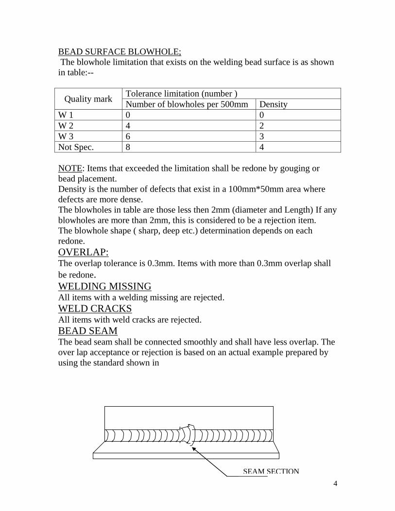
BEAD SEAM The bead seam shall be connected smoothly and shall have less overlap. The
over lap acceptance or rejection is based on an actual example prepared by
using the standard shown in
SEAM SECTION
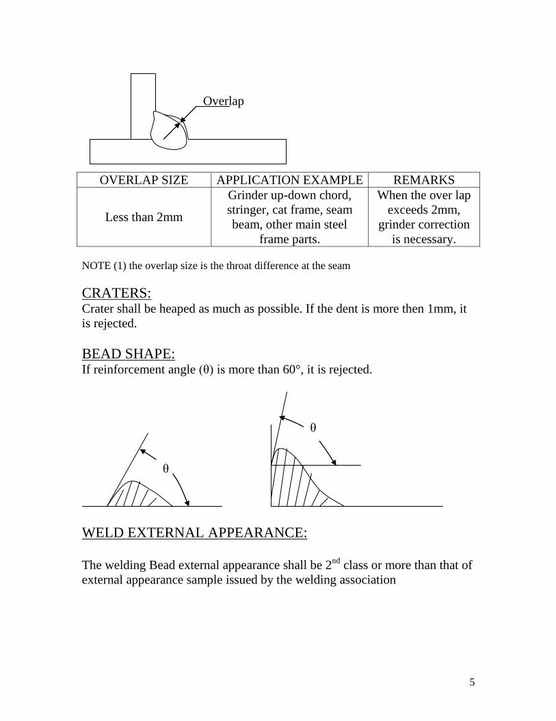
5
OVERLAP SIZE APPLICATION EXAMPLE REMARKS
Less than 2mm
Grinder up-down chord,
stringer, cat frame, seam
beam, other main steel
frame parts.
When the over lap
exceeds 2mm,
grinder correction
is necessary.
NOTE (1) the overlap size is the throat difference at the seam
CRATERS: Crater shall be heaped as much as possible. If the dent is more then 1mm, it
is rejected.
BEAD SHAPE: If reinforcement angle (θ) is more than 60°, it is rejected.
WELD EXTERNAL APPEARANCE:
The welding Bead external appearance shall be 2
nd class or more than that of
external appearance sample issued by the welding association
Overlap
θ
θ
6
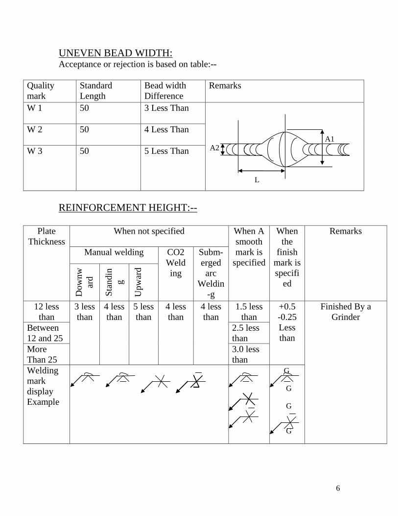
UNEVEN BEAD WIDTH: Acceptance or rejection is based on table:--
Quality
mark
Standard
Length
Bead width
Difference
Remarks
W 1 50 3 Less Than
W 2 50 4 Less Than
W 3 50 5 Less Than
REINFORCEMENT HEIGHT:--
Plate
Thickness
When not specified When A
smooth
mark is
specified
When
the
finish
mark is
specifi
ed
Remarks
Manual welding CO2
Weld
ing
Subm-
erged
arc
Weldin
-g Dow
nw
ard
Sta
ndin
g
Upw
ard
12 less
than
3 less
than
4 less
than
5 less
than
4 less
than
4 less
than
1.5 less
than
+0.5
-0.25
Less
than
Finished By a
Grinder
Between
12 and 25
2.5 less
than
More
Than 25
3.0 less
than
Welding
mark
display
Example
A1
L
A2
G
G
G
G