Embed Size (px)
Citation preview
WELDING SYMBOLSWelding symbols, like sign post's are informational directors. They are placed on drawings by Welding engineers and their purpose is to relay information to the weld operator. In many instance's the information relayed is very simple.Occasionally it is necessary for the engineer to relay complicated information. Therefore it is important that weld operators understand the symbols and are capable of interpreting the needs of the engineer.For the most part weld symbols are standard throughout the world, although there are symbols that are devised and used only by the company that devised them.
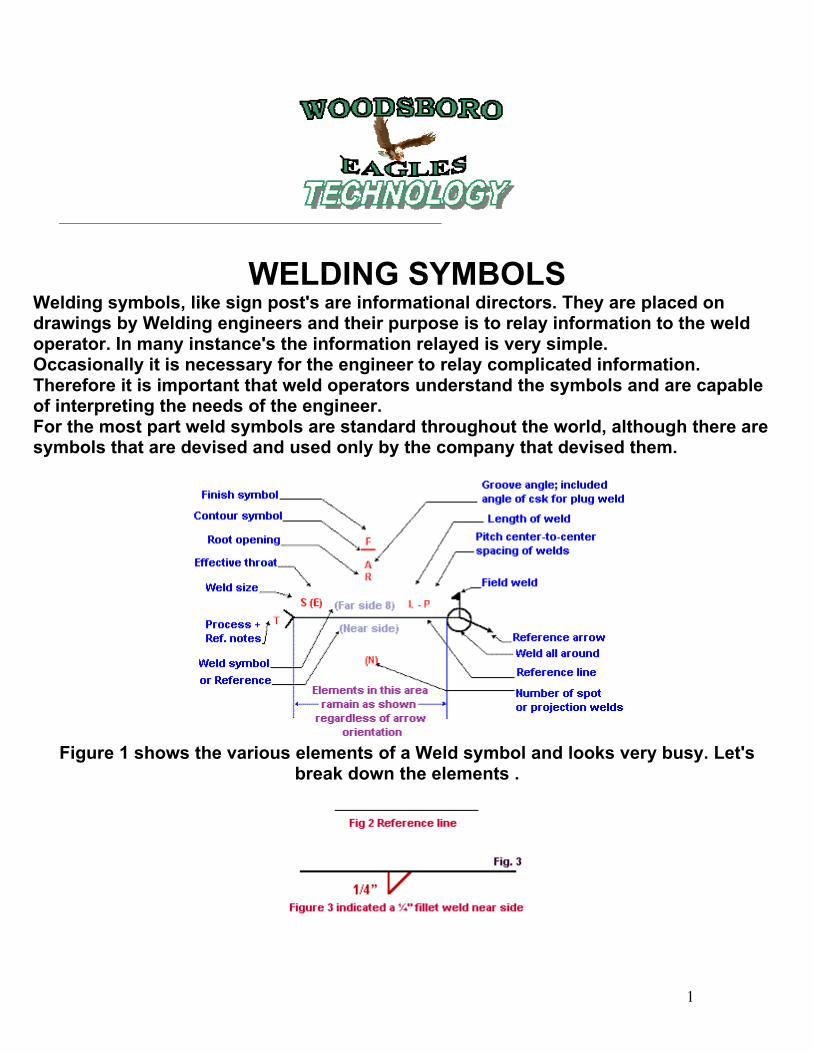
Figure 1 shows the various elements of a Weld symbol and looks very busy. Let's break down the elements .
1
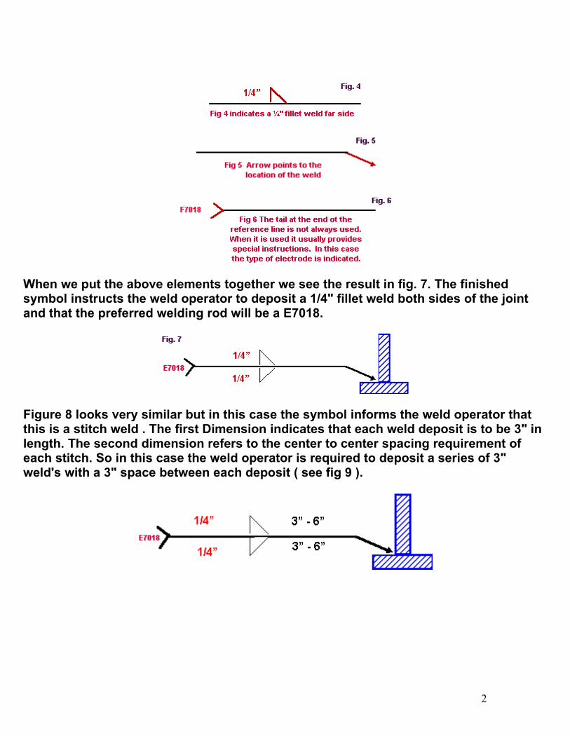
When we put the above elements together we see the result in fig. 7. The finished symbol instructs the weld operator to deposit a 1/4" fillet weld both sides of the joint and that the preferred welding rod will be a E7018.
Figure 8 looks very similar but in this case the symbol informs the weld operator that this is a stitch weld . The first Dimension indicates that each weld deposit is to be 3" in length. The second dimension refers to the center to center spacing requirement of each stitch. So in this case the weld operator is required to deposit a series of 3" weld's with a 3" space between each deposit ( see fig 9 ).
2
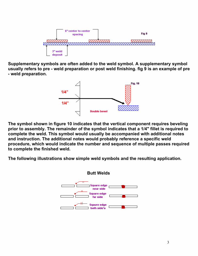
Supplementary symbols are often added to the weld symbol. A supplementary symbol usually refers to pre - weld preparation or post weld finishing. fig 9 is an example of pre - weld preparation.
The symbol shown in figure 10 indicates that the vertical component requires beveling prior to assembly. The remainder of the symbol indicates that a 1/4" fillet is required to complete the weld. This symbol would usually be accompanied with additional notes and instruction. The additional notes would probably reference a specific weld procedure, which would indicate the number and sequence of multiple passes required to complete the finished weld.
The following illustrations show simple weld symbols and the resulting application.
Butt Welds
3
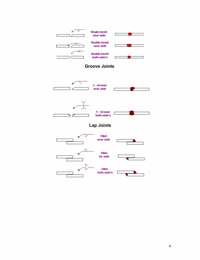
Groove Joints
Lap Joints
4
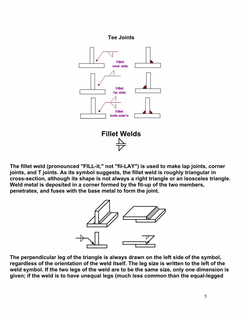
Tee Joints
Fillet Welds
The fillet weld (pronounced "FILL-it," not "fil-LAY") is used to make lap joints, corner joints, and T joints. As its symbol suggests, the fillet weld is roughly triangular in cross-section, although its shape is not always a right triangle or an isosceles triangle. Weld metal is deposited in a corner formed by the fit-up of the two members, penetrates, and fuses with the base metal to form the joint.
The perpendicular leg of the triangle is always drawn on the left side of the symbol, regardless of the orientation of the weld itself. The leg size is written to the left of the weld symbol. If the two legs of the weld are to be the same size, only one dimension is given; if the weld is to have unequal legs (much less common than the equal-legged
5
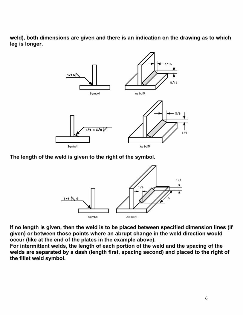
weld), both dimensions are given and there is an indication on the drawing as to which leg is longer.
The length of the weld is given to the right of the symbol.
If no length is given, then the weld is to be placed between specified dimension lines (if given) or between those points where an abrupt change in the weld direction would occur (like at the end of the plates in the example above). For intermittent welds, the length of each portion of the weld and the spacing of the welds are separated by a dash (length first, spacing second) and placed to the right of the fillet weld symbol.
6
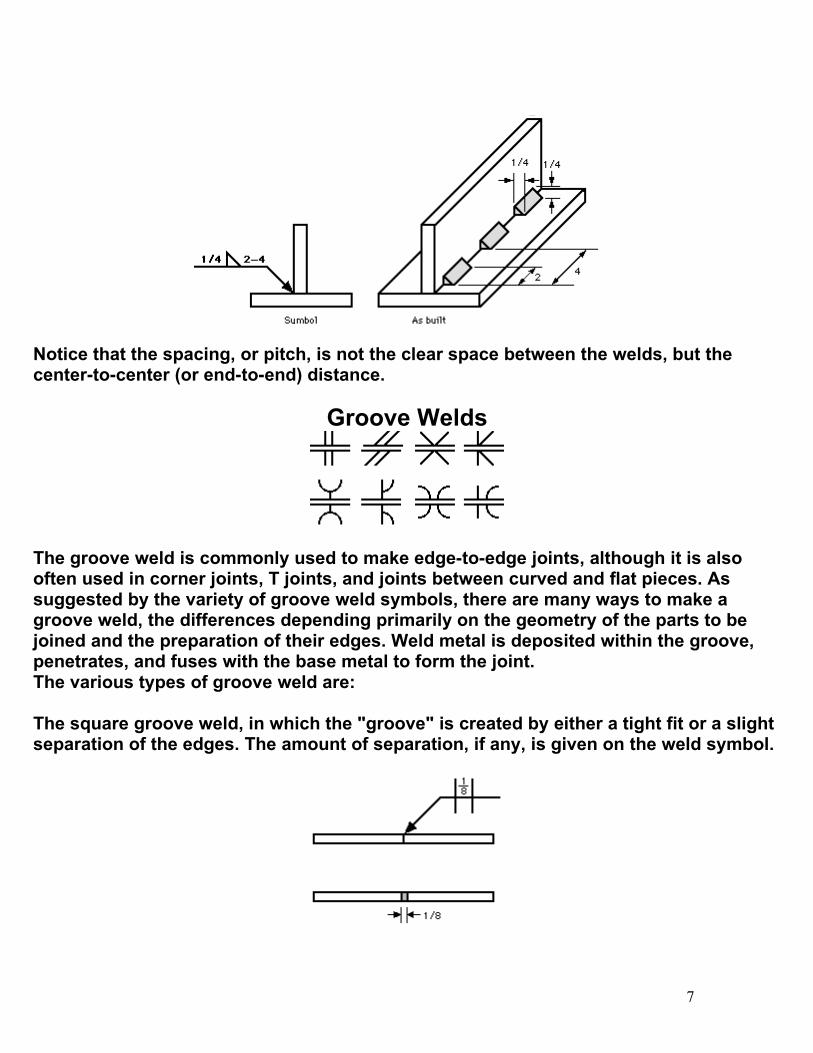
Notice that the spacing, or pitch, is not the clear space between the welds, but the center-to-center (or end-to-end) distance.
Groove Welds
The groove weld is commonly used to make edge-to-edge joints, although it is also often used in corner joints, T joints, and joints between curved and flat pieces. As suggested by the variety of groove weld symbols, there are many ways to make a groove weld, the differences depending primarily on the geometry of the parts to be joined and the preparation of their edges. Weld metal is deposited within the groove, penetrates, and fuses with the base metal to form the joint. The various types of groove weld are:
The square groove weld, in which the "groove" is created by either a tight fit or a slight separation of the edges. The amount of separation, if any, is given on the weld symbol.
7
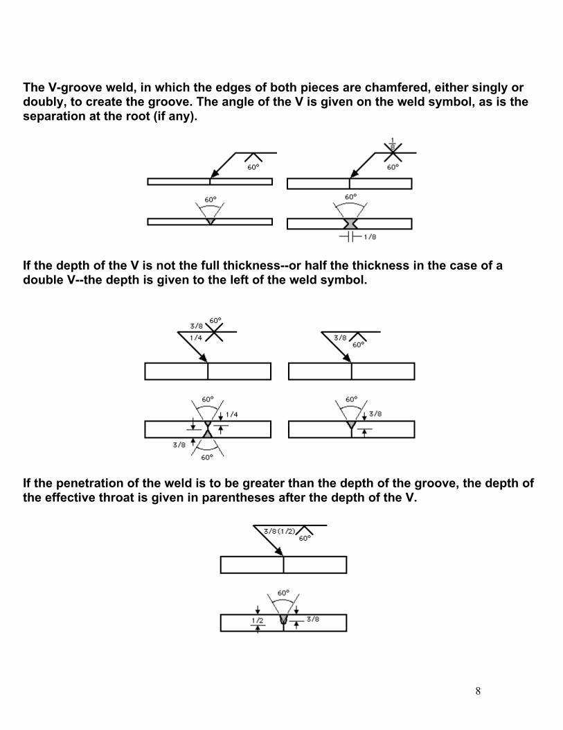
The V-groove weld, in which the edges of both pieces are chamfered, either singly or doubly, to create the groove. The angle of the V is given on the weld symbol, as is the separation at the root (if any).
If the depth of the V is not the full thickness--or half the thickness in the case of a double V--the depth is given to the left of the weld symbol.
If the penetration of the weld is to be greater than the depth of the groove, the depth of the effective throat is given in parentheses after the depth of the V.
8
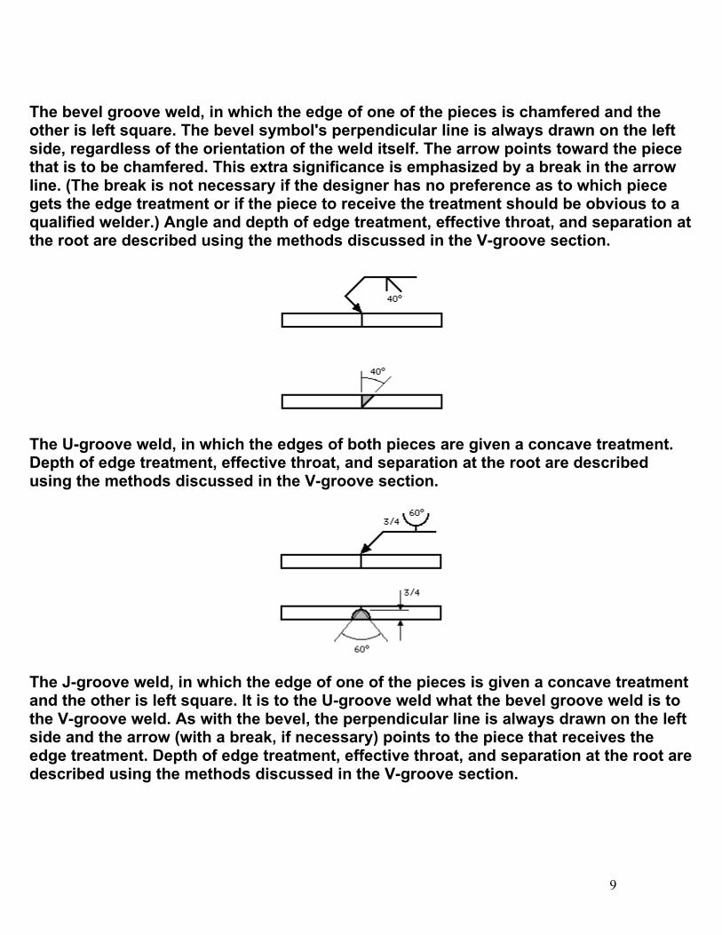
The bevel groove weld, in which the edge of one of the pieces is chamfered and the other is left square. The bevel symbol's perpendicular line is always drawn on the left side, regardless of the orientation of the weld itself. The arrow points toward the piece that is to be chamfered. This extra significance is emphasized by a break in the arrow line. (The break is not necessary if the designer has no preference as to which piece gets the edge treatment or if the piece to receive the treatment should be obvious to a qualified welder.) Angle and depth of edge treatment, effective throat, and separation at the root are described using the methods discussed in the V-groove section.
The U-groove weld, in which the edges of both pieces are given a concave treatment. Depth of edge treatment, effective throat, and separation at the root are described using the methods discussed in the V-groove section.
The J-groove weld, in which the edge of one of the pieces is given a concave treatment and the other is left square. It is to the U-groove weld what the bevel groove weld is to the V-groove weld. As with the bevel, the perpendicular line is always drawn on the left side and the arrow (with a break, if necessary) points to the piece that receives the edge treatment. Depth of edge treatment, effective throat, and separation at the root are described using the methods discussed in the V-groove section.
9
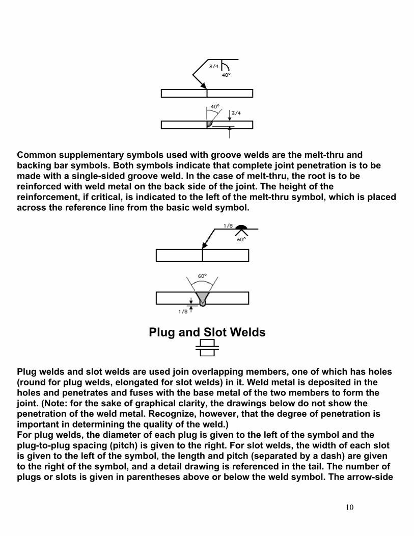
Common supplementary symbols used with groove welds are the melt-thru and backing bar symbols. Both symbols indicate that complete joint penetration is to be made with a single-sided groove weld. In the case of melt-thru, the root is to be reinforced with weld metal on the back side of the joint. The height of the reinforcement, if critical, is indicated to the left of the melt-thru symbol, which is placed across the reference line from the basic weld symbol.
Plug and Slot Welds
Plug welds and slot welds are used join overlapping members, one of which has holes (round for plug welds, elongated for slot welds) in it. Weld metal is deposited in the holes and penetrates and fuses with the base metal of the two members to form the joint. (Note: for the sake of graphical clarity, the drawings below do not show the penetration of the weld metal. Recognize, however, that the degree of penetration is important in determining the quality of the weld.) For plug welds, the diameter of each plug is given to the left of the symbol and the plug-to-plug spacing (pitch) is given to the right. For slot welds, the width of each slot is given to the left of the symbol, the length and pitch (separated by a dash) are given to the right of the symbol, and a detail drawing is referenced in the tail. The number of plugs or slots is given in parentheses above or below the weld symbol. The arrow-side
10
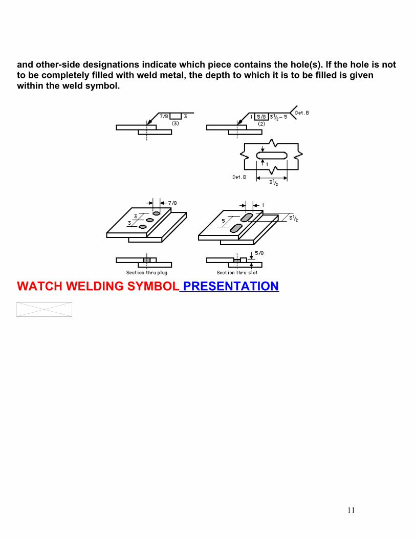
and other-side designations indicate which piece contains the hole(s). If the hole is not to be completely filled with weld metal, the depth to which it is to be filled is given within the weld symbol.
WATCH WELDING SYMBOL PRESENTATION
11
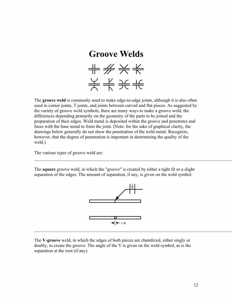
Groove Welds
The groove weld is commonly used to make edge-to-edge joints, although it is also often used in corner joints, T joints, and joints between curved and flat pieces. As suggested by the variety of groove weld symbols, there are many ways to make a groove weld, the differences depending primarily on the geometry of the parts to be joined and the preparation of their edges. Weld metal is deposited within the groove and penetrates and fuses with the base metal to form the joint. (Note: for the sake of graphical clarity, the drawings below generally do not show the penetration of the weld metal. Recognize, however, that the degree of penetration is important in determining the quality of the weld.)
The various types of groove weld are:
The square groove weld, in which the "groove" is created by either a tight fit or a slight separation of the edges. The amount of separation, if any, is given on the weld symbol.
The V-groove weld, in which the edges of both pieces are chamfered, either singly or doubly, to create the groove. The angle of the V is given on the weld symbol, as is the separation at the root (if any).
12
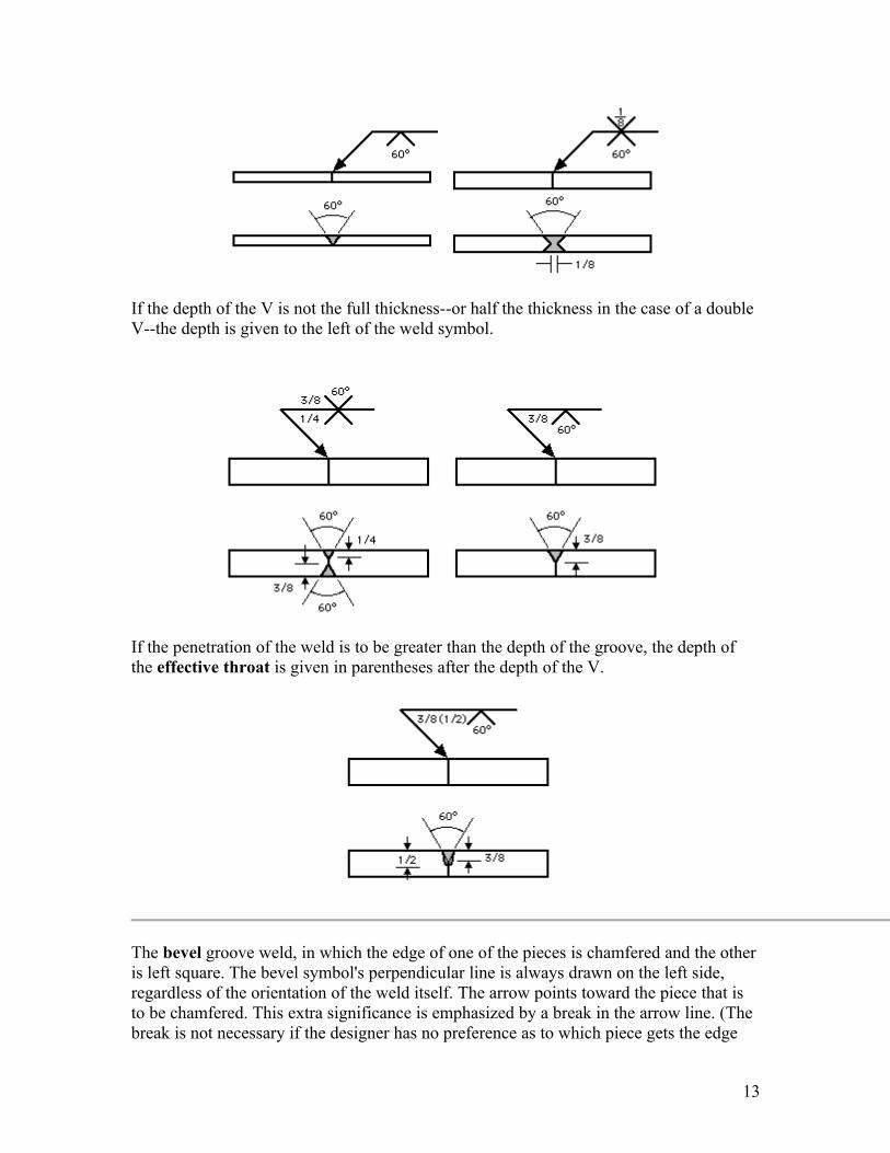
If the depth of the V is not the full thickness--or half the thickness in the case of a double V--the depth is given to the left of the weld symbol.
If the penetration of the weld is to be greater than the depth of the groove, the depth of the effective throat is given in parentheses after the depth of the V.
The bevel groove weld, in which the edge of one of the pieces is chamfered and the other is left square. The bevel symbol's perpendicular line is always drawn on the left side, regardless of the orientation of the weld itself. The arrow points toward the piece that is to be chamfered. This extra significance is emphasized by a break in the arrow line. (The break is not necessary if the designer has no preference as to which piece gets the edge
13
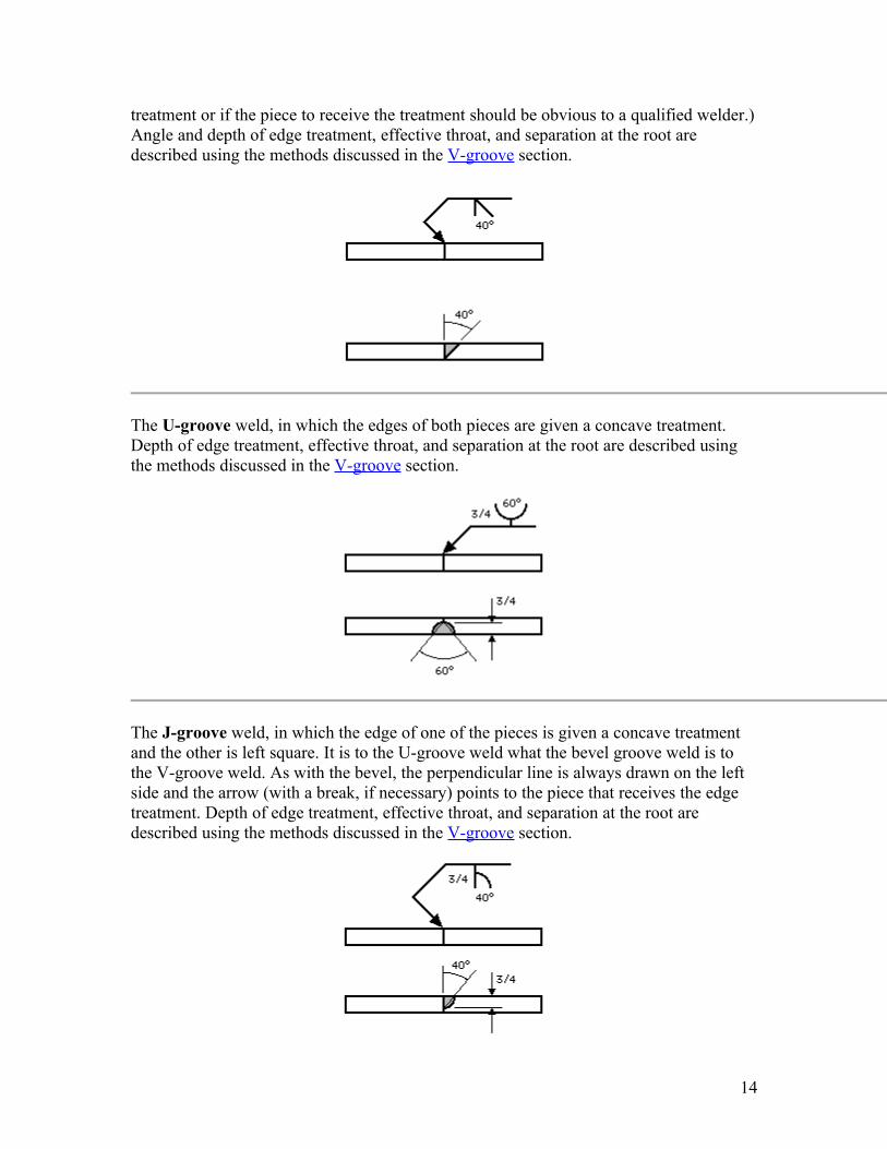
treatment or if the piece to receive the treatment should be obvious to a qualified welder.) Angle and depth of edge treatment, effective throat, and separation at the root are described using the methods discussed in the V-groove section.
The U-groove weld, in which the edges of both pieces are given a concave treatment. Depth of edge treatment, effective throat, and separation at the root are described using the methods discussed in the V-groove section.
The J-groove weld, in which the edge of one of the pieces is given a concave treatment and the other is left square. It is to the U-groove weld what the bevel groove weld is to the V-groove weld. As with the bevel, the perpendicular line is always drawn on the left side and the arrow (with a break, if necessary) points to the piece that receives the edge treatment. Depth of edge treatment, effective throat, and separation at the root are described using the methods discussed in the V-groove section.
14
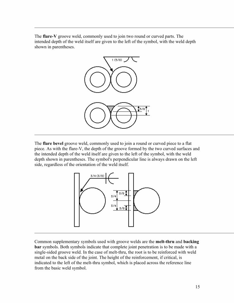
The flare-V groove weld, commonly used to join two round or curved parts. The intended depth of the weld itself are given to the left of the symbol, with the weld depth shown in parentheses.
The flare bevel groove weld, commonly used to join a round or curved piece to a flat piece. As with the flare-V, the depth of the groove formed by the two curved surfaces and the intended depth of the weld itself are given to the left of the symbol, with the weld depth shown in parentheses. The symbol's perpendicular line is always drawn on the left side, regardless of the orientation of the weld itself.
Common supplementary symbols used with groove welds are the melt-thru and backing bar symbols. Both symbols indicate that complete joint penetration is to be made with a single-sided groove weld. In the case of melt-thru, the root is to be reinforced with weld metal on the back side of the joint. The height of the reinforcement, if critical, is indicated to the left of the melt-thru symbol, which is placed across the reference line from the basic weld symbol.
15
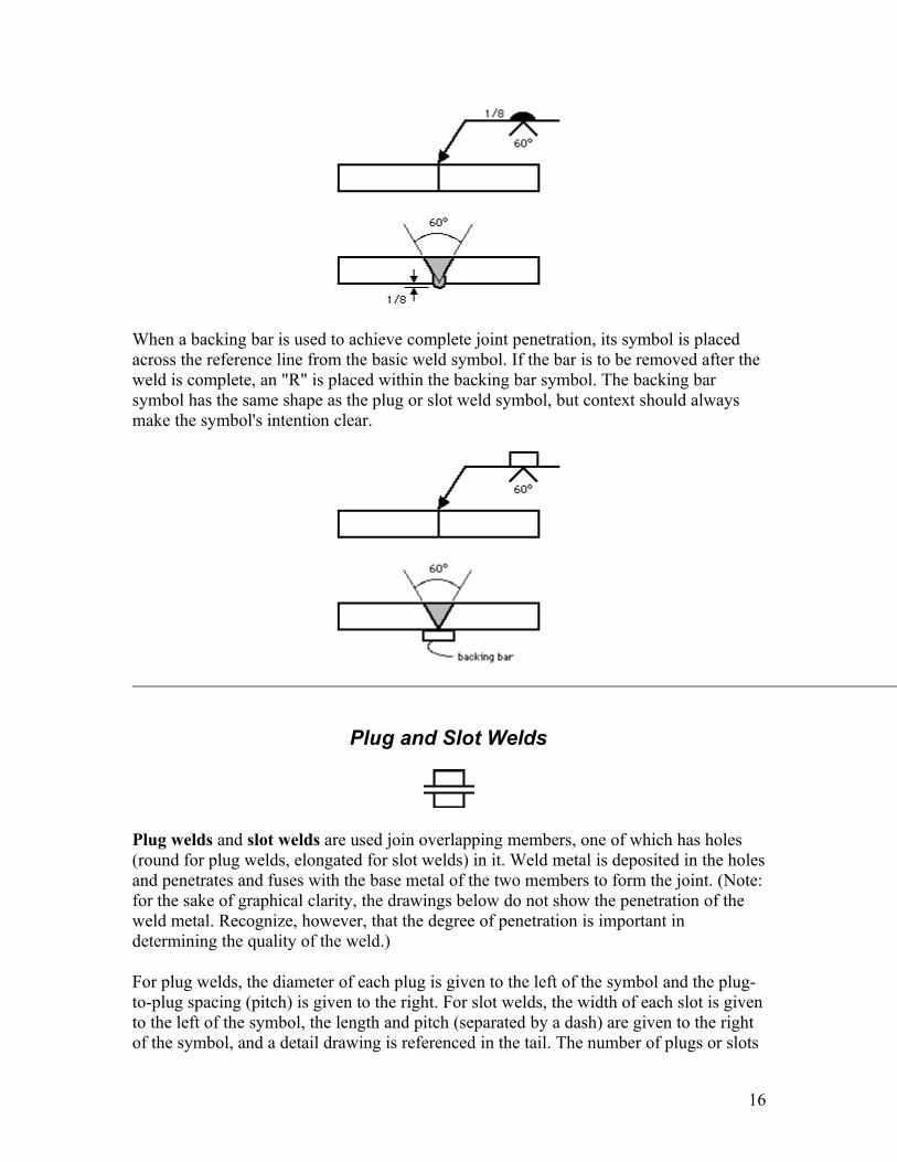
When a backing bar is used to achieve complete joint penetration, its symbol is placed across the reference line from the basic weld symbol. If the bar is to be removed after the weld is complete, an "R" is placed within the backing bar symbol. The backing bar symbol has the same shape as the plug or slot weld symbol, but context should always make the symbol's intention clear.
Plug and Slot Welds
Plug welds and slot welds are used join overlapping members, one of which has holes (round for plug welds, elongated for slot welds) in it. Weld metal is deposited in the holes and penetrates and fuses with the base metal of the two members to form the joint. (Note: for the sake of graphical clarity, the drawings below do not show the penetration of the weld metal. Recognize, however, that the degree of penetration is important in determining the quality of the weld.)
For plug welds, the diameter of each plug is given to the left of the symbol and the plug-to-plug spacing (pitch) is given to the right. For slot welds, the width of each slot is given to the left of the symbol, the length and pitch (separated by a dash) are given to the right of the symbol, and a detail drawing is referenced in the tail. The number of plugs or slots
16
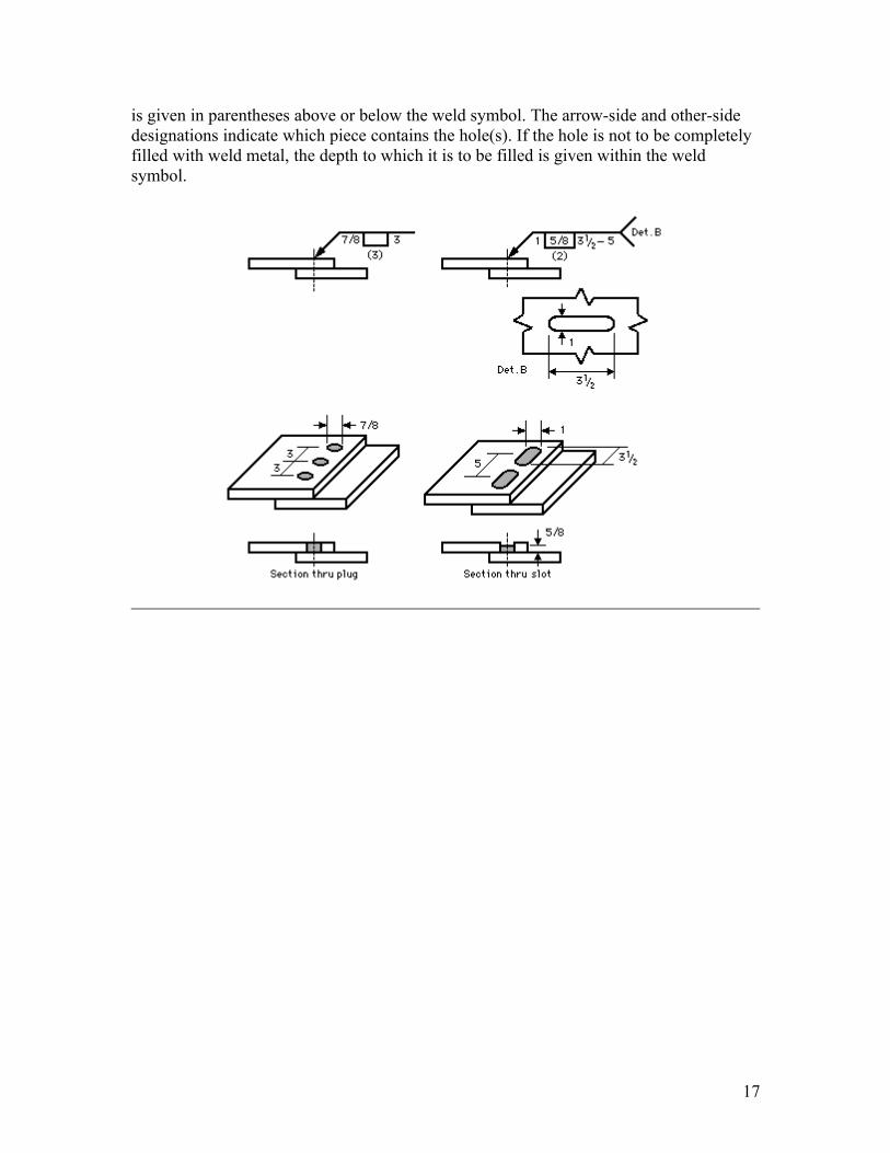
is given in parentheses above or below the weld symbol. The arrow-side and other-side designations indicate which piece contains the hole(s). If the hole is not to be completely filled with weld metal, the depth to which it is to be filled is given within the weld symbol.
17