Embed Size (px)
DESCRIPTION
welding metaluurgy
Citation preview

Chapter – 29
The Metallurgy of welding :Welding Design and Process selection

Topics to DiscussTopics to Discuss
• Introduction
• Welded joint
• Weldability
• Testing welding joint
• Weld design and process selection

IntroductionIntroduction
• Strength ,ductility ,toughness of welded joint
• Micro structure and grain size depends on the temperatures
• Weld quality depends on geometry,presence of cracks,residual stresses ,inclusions and oxide films…

Welded JointWelded Joint
• 3-Distinct zones• Base metal • Heat – affected zone • Weld metal• Metallurgy and properties of second and third zone depend
strongly• On metals joined , welding process, filler metals used & on
process variables.• Autogenously is joint produced without the filler metal• Weld zone is composed of resolidified base metal
Fusion Weld ZoneFusion Weld Zone
Fig : Characteristics of a typical fusion weld zone in oxyfuel gas and arc welding.
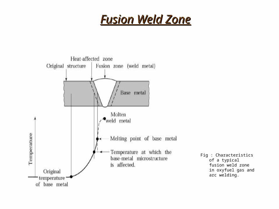
Grain StructureGrain Structure
Fig : Grain structure in (a) a deep weld (b) a shallow weld. Note that the grains in the solidified weld metal are perpendicular to the surface of the base metal. In a good weld, the solidification line at the center in the deep weld shown in (a) has grain migration, which develops uniform strength in the weld bead.
(a) (b)

Solidification of Weld metalSolidification of Weld metal
• Solidification begins with formation of columnar grains which is similar to casting
• Grains relatively long and form parallel to the heat flow• Grain structure and size depend on the specific alloy• Weld metal has a cast structure because it has cooled
slowly, it has grain structure• Results depends on alloys ,composition and thermal
cycling to which the joint is subjected.• Pre-heating is important for metals having high thermal
conductivity

Weld BeadsWeld Beads
Fig : (a) Weld bead (on a cold-rolled nickel strip) produced by a laser beam. (b) Microhardness profile across the weld bead. Note the lower hardness of the weld bead compared to the base metal.
(a) (b)

Heat affected ZoneHeat affected Zone
• Heat effected zone is within the metal itself • Properties depend on • Rate of heat input and cooling• Temperature to which the zone was raised• Original grain size ,Grain orientation , Degree of prior cold
work• The strength and hardness depend partly on how original
strength and hardness of the base metal was developed prior to the welding
• Heat applied during welding Recrystallises elongated grains of cold worked base metal

CorrosionCorrosion
Fig : Intergrannular corrosion of a 310-stainless-steel welded tube after exposure to a caustic solution. The weld line is at the center of the photograph. Scanning electron micrographs at 20X.
Weld QualityWeld Quality
• Welding discontinuities can be caused by inadequate or careless application
• The major discontinuities that affect weld quality are • Porosity• Slag Inclusions• Incomplete fusion and penetration• Weld profile• Cracks• Lamellar tears• Surface damage• Residual stresses

Porosity• Caused by gases released during melting of the weld area but
trapped during solidification, chemical reactions, Contaminants• They are in form of spheres or elongated pockets• Porosity can be reduced by • Proper selection of electrodes• Improved welding techniques• Proper cleaning and prevention of contaminants• Reduced welding speeds
Slag Inclusions• Compounds such as oxides ,fluxes, and electrode-coating materials
that are trapped in the weld Zone• Prevention can be done by following practices :• Cleaning the weld bed surface before the next layer is deposited• Providing enough shielding gas• Redesigning the joint

Incomplete Fusion and Penetration
• Produces lack of weld beads
• Practices for better weld :
• Raising the temperature of the base metal
• Cleaning the weld area, prior to the welding
• Changing the joint design and type of electrode
• Providing enough shielding gas

Penetration:• Incomplete penetration occurs when the depth of the welded joint is
insufficient• Penetration can be improved by the following practices :• Increasing the heat Input• Reducing the travel speed during the welding• Changing the joint design• Ensuring the surfaces to be joined fit properly

Weld Profile:
• Under filling results when the joint is not filed with the proper amount of weld metal.
• Undercutting results from the melting away of the base metal and consequent generation of a groove in the shape of a sharp recess or notch.
• Overlap is a surface discontinuity usually caused by poor welding practice and by the selection of improper material.

Discontinuities in Fusion Welds
Fig : Schematic illustration of various discontinuities in fusion welds.

CracksCracks
• Cracks occur in various directions and various locations
Factors causing cracks:
• Temperature gradients that cause thermal stresses in the weld zone
• Variations in the composition of the weld zone.
• Embrittlement of grain boundaries
• Inability if the weld metal to contract during cooling

CracksCracks
Fig : Types of cracks (in welded joints) caused by thermal stresses that develop during solidification and contraction of the weld bead and the surrounding structure. (a) Crater cracks (b) Various types of cracks in butt and T joints.

CracksCracks
• Cracks are classified as Hot or Cold.• Hot cracksHot cracks – Occur at elevated temperatures• Cold cracksCold cracks – Occur after solidification• Basic crack prevention measures :• Change the joint design ,to minimize stresses from
the shrinkage during cooling• Change the parameters, procedures, the sequence
of welding process• Preheat the components to be welded• Avoid rapid cooling of the welded components
Cracks in Weld Beads
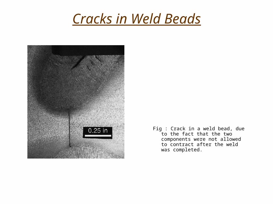
Fig : Crack in a weld bead, due to the fact that the two components were not allowed to contract after the weld was completed.

Lamellar tears :
• Occurred due to the shrinkage of the restrained components in the structure during cooling.
• Can be avoided by providing for shrinkage of the members
• Changing the joint design
• Surface Damage : These discontinuities may adversely affect the properties of welded structure, particularly for notch sensitive metals.

Residual Stresses:
• Caused because of localized heating and cooling during welding, expansion and contraction of the weld area causes residual stresses in the work piece.
• Distortion,Warping and buckling of welded parts
• Stress corrosion cracking
• Further distortion if a portion of the welded structure is subsequently removed
• Reduced fatigue life
Distortion after Welding
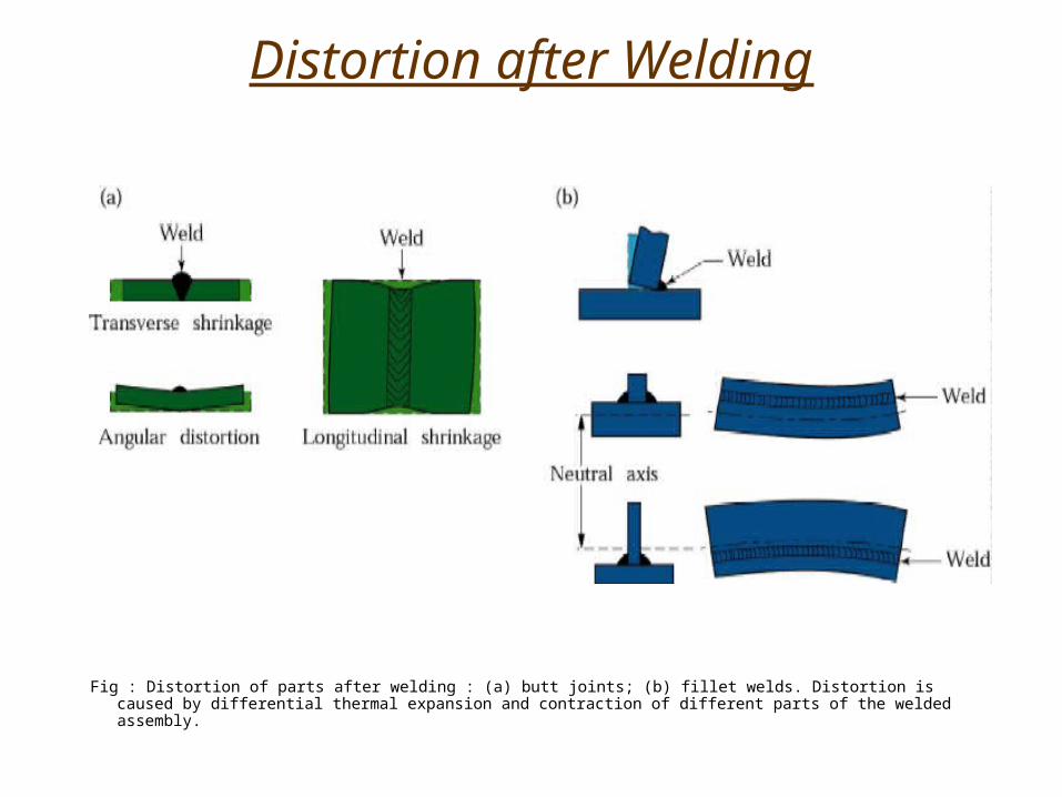
Fig : Distortion of parts after welding : (a) butt joints; (b) fillet welds. Distortion is caused by differential thermal expansion and contraction of different parts of the welded assembly.

Residual Stresses developed during welding
Fig : Residual stresses developed during welding of a butt joint.
Stress relieving of welds :
• Preheating reduces reduces problems caused by preheating the base metal or the parts to be welded
• Heating can be done electrically,in furnace,for thin surfaces radiant lamp or hot air blast
• Some other methods of stress relieving : Peening, hammering or surface rolling

Weldability:• Capacity to be welded into a specific structure that has certain
properties and characteristics and will satisfactorily meet service requirements
• Thorough knowledge of the phase diagram is essential
• Factors such as strength, toughness, ductility, notch sensitivity, elastic modulus, specific heat, melting point, thermal expansion, surface tension characteristics of the molten metal, corrosion resistance.
Testing Welded Joints
• Quality of the welding joint is established by welded joint
• Each technique has capabilities ,limitations and sensitivity reliability and requirement for special equipment and operator skill.

Destructive Techniques
Tension Test :• Longitudinal and transverse tension tests are performed• Stress strain curves are obtained
Tension-Shear Test • Specifically prepared to simulate actual welded joints and procedures.• Specimen subjected to tension and shear strength of the weld metal
Bend test :• Determines ductility and strength of welded joints.• The welded specimen is bend around a fixture • The specimens are tested in three-point transverse bending • These tests help to determine the relative ductility and strength of the
welded joints

Destructive Techniques
Fig : Two types of specimens for tension-shear testing of welded joints.
Fig : (a) Wrap-around bend test method. (b) Three-point bending of welded specimens.
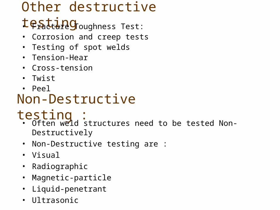
Other destructive testing• Fracture Toughness Test:• Corrosion and creep tests• Testing of spot welds• Tension-Hear• Cross-tension• Twist• Peel
Non-Destructive testing :• Often weld structures need to be tested Non-Destructively
• Non-Destructive testing are :
• Visual
• Radiographic
• Magnetic-particle
• Liquid-penetrant
• Ultrasonic

Testing of Spot Welds
Fig : (a) Tension-shear test for spot welds. (b) Cross-Tension test. (c) Twist test. (d) Peel test

Weld design & Process Selection
Considerations:
• Configuration of the components or structure to be welded, and their thickness and size
• Methods used to manufacture the components
• Service requirements, Type of loading and stresses generated
• Location, accessibility and ease of welding
• Effects of distortion and discoloration
• Appearance
• Costs involved

Welding Design Guidelines
Fig : Design guidelines for welding

General Design Guidelines
Fig : Standard identification and symbols for welds

Weld Design Selection
Fig : Weld Design Selection

THE END


![Journal of American Science 0203arc welding, atomic hydrogen welding, shielded metal arc welding, plasma arc welding, electroslag welding, etc. Arc welding has been described [3] to](https://img.pdfslide.us/doc/110x75/5ec0a6e76045b75960496969/journal-of-american-science-arc-welding-atomic-hydrogen-welding-shielded-metal.jpg)