Embed Size (px)
Citation preview
lecture 8
Welding Metallurgy
Heat Flow in Welding
p1
Lecture Scope
• Basic features of welding heat transfer -
• Relevant heat flow theory and solutions
p2
(

Significance of Thermal Effects
• The thermal conditions in and near weldsgovern the resulting metallurgical structure,mechanical properties, residual stress anddistortion
• Of particular significance are:- Weld bead area- Weld solidification rate- Peak temperatures in the Heat Affected Zone (HAl)- Width of HAl- Cooling rates in the weld and HAl
Lecture 8 p3
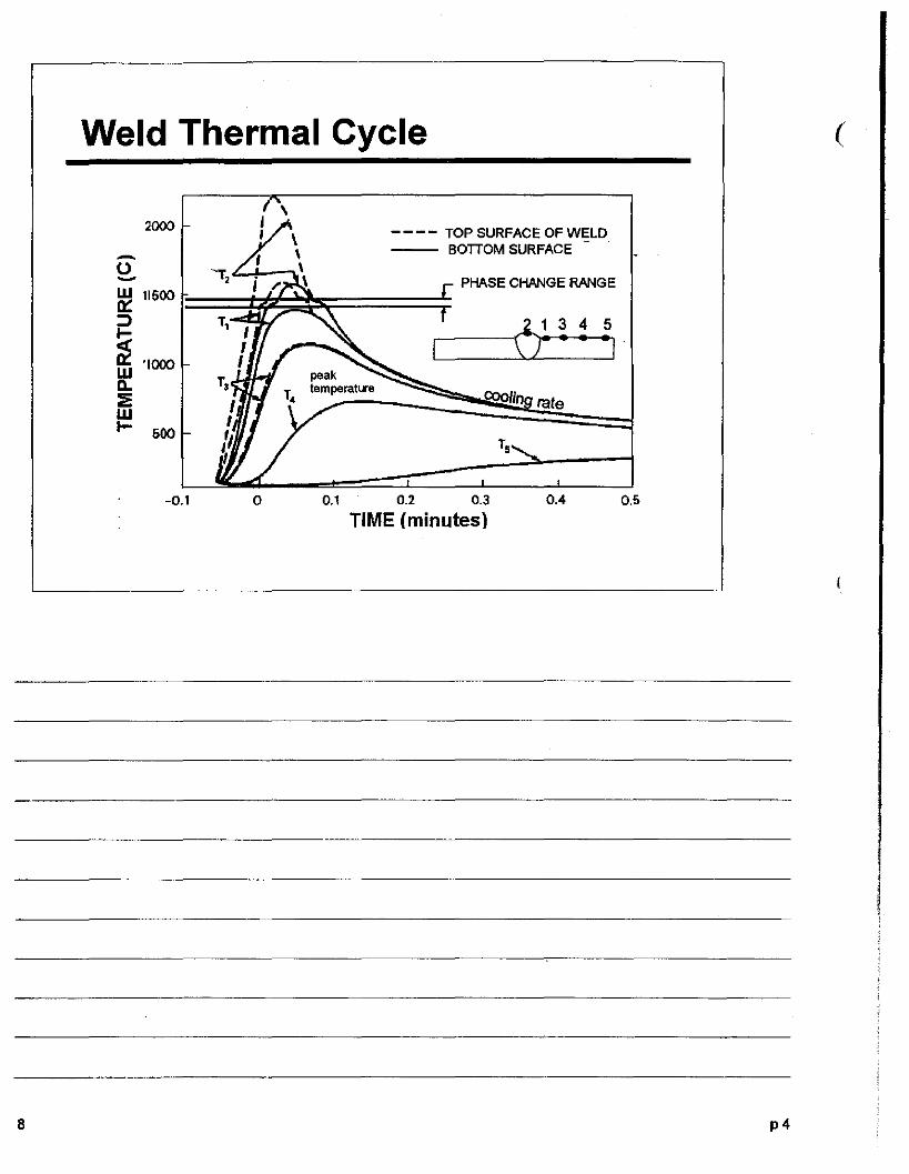
Weld Thermal Cycle (
,2000
- - - - TOP SURFACE OF WELD
- BOTTOM SURFACE
0 -,.,~ PHASE CHANGE RANGEW 11500It:::>
6~~4 5
i • -,W
'1000
D..::i!: 1Xlolin tateWI- 500
Ts
-0.1 0 0.1 0.2 0.3 0.4 0.5
TIME (minutes)
8 p4
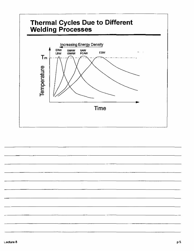
Thermal Cycles Due to DifferentWelding Processes
Lecture 8
Tm
Increasing Energy Density..EBW SMAW SAWLBW GMAW FCAW ESW
Time
p5

Multiple Pass Weld Cycles (
1500 ,------r----,...-----r------,
~ 1000
~
~II:Wll..:::;: 500w.....
Interpass Temperature
400300100 200
TIME, SECONDS
O~'--__..L- ...L. ....L_______.J
o
p6
Heat Balance
• The power delivered to the work from th.e arcis qa = 'lVI
• Thermal energy is dissipated by conduction inthe solid and by convection and radiation tothe surroundings
• Conduction in the solid predominates
Lecture 8 pi

8
Weld Area
~A1=FilierArea
~A2 = Area of base_metal melted
Weld Area Aw = A1 + A2 .L--<....L--L...'------"<-L----L.J.'--"':.L.-...,LL~
• Heat input must be sufficient to overcome losses and tosupply the energy needed for melting
• The minimum power required for melting is HAwv where His the energy required to melt unit volume of metal
• Melting effidency f2 =(HAwv)/(fJVI)
• Higher energy densities reduce heat losses and givegreater melting efficiency
p8
(
Lecture 8
Weld Area
• Assume arc efficiency, fl, and the melting efficiency'2 do notvary greatly for a given welding process.
• From the previous equations it can be seen that the crosssection of a single weld bead is roughly proportional to theenergy input, Le.-Aw = f2 "V/IHv
• For example, consider an arc weld on steel made under thefollowing conditions:- V=10V,-/=200A,-v=5mmls,
-"=.9,- f2 =.3,- H =10 Jlmm A 3
• Then Aw =11. 3 mm
p9
8
Heat Flow Theory
• Heat flow in the solid is determined by: - workpiece thickness- edge, end effects- thennal conductivity and specific heat- heat source distribution- convection in the weld pool-latent heat absorption and release
P 10
(
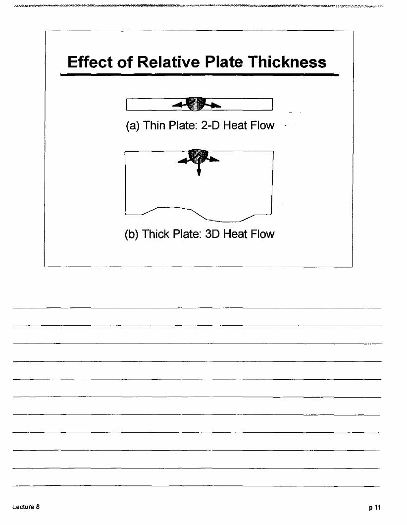
Effect of Relative Plate Thickness
---~---(a) Thin Plate: 2-D Heat Flow - .
(b) Thick Plate: 3D Heat Flow
Lecture 8 P 11
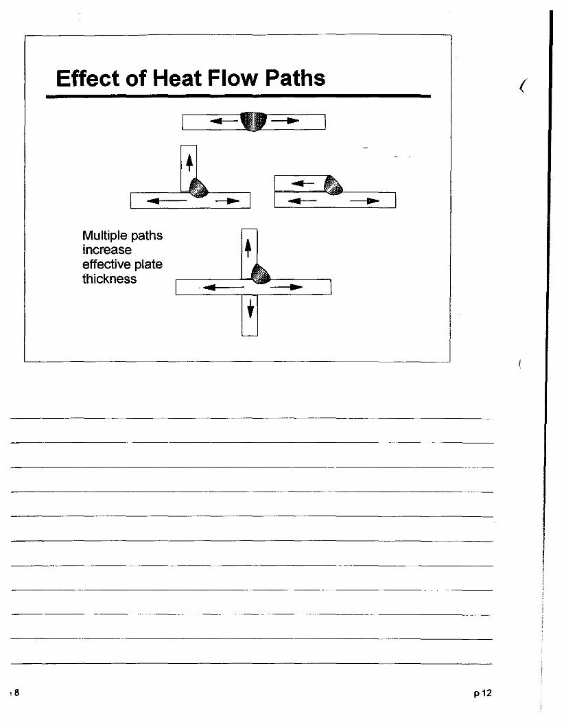
Effect of Heat Flow Paths (
.. ..-.--..- .. I
,8
Multiple paths ,increase Teffective platethickness -... ..
+
p12
Lecture 8
Heat Flow Solutions
• Computer numerical modelling techniques are nowcapable of solving weld thermo-mechanical problems witha high degree of accuracy
• Traditional analytical solutions for heat conduction are stilluseful and give insights on the effects of welding variables
p13
Heat Flow Equation
With simplifying assumptions, steady state heat conduction ina moving solid may be described by the following equation:
·8
where
ex = K/pC p
ex =thermal diffusivityK = thermal conductivityp =densityC = specific heat
p
(1 )
p14

Solutions to Heat Flow Equation
Solution of Equation (1) gives the following expressions forthe temperature field round a "quasi-stationary" heat source
(a) Thin Plate 2D Heat Flow
T = q e -v(r-x)/2a (2)21tKr
(b) Thick Plate 3D Heat Flow
T = q e vx/2a K ( vr ) (3)21tK 0 2ex
K 0 is Bessel function (tabulated) and r= ";x 2 +Y 2 + Z 2
Lecture 8 p15

Peak Temperature
The following equation applies to thin plate (2D)
1 V2rcepc hyv 1= p + (4)
T -T q T -Tp 0 m 0
Tp = peak temperatureTo = initial plate temperatureTm = melting temperaturee = Base of natural logarithms (2.718)h = plate thicknessy = distance from fusion line
P 16
(
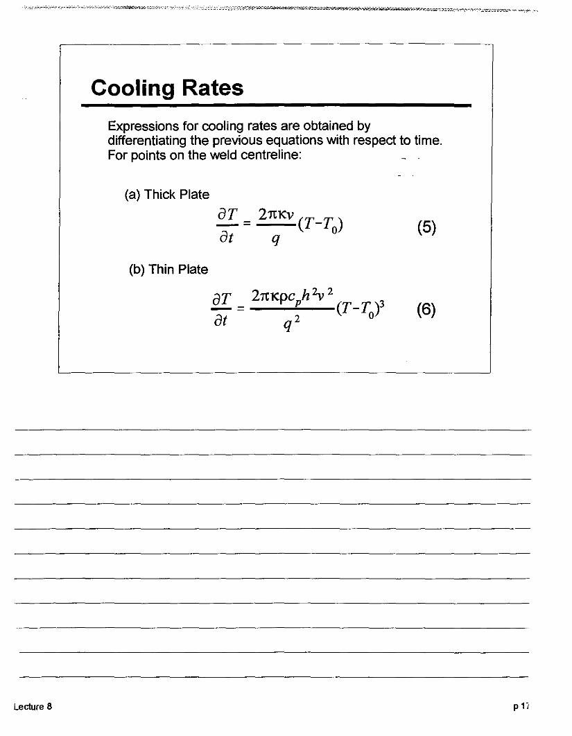
Cooling Rates
Expressions for cooling rates are obtained bydifferentiating the previous equations with respect to time.For points on the weld centreline:
Lecture 8
(a) Thick Plate
!!I- = 21t1<v (T-T)at q 0
(b) Thin Plate
(5)
(6)
p1i
6
Effects of Welding Variables
• These equations show that weld bead area,peak temperatures, weld width, and cooUngrates are determined by:- Heat input per unit length qlv, and-Initial plate temperature To, or preheat temperature
• The effects of increased heat input andpreheat temperature are to:- increase peak temperatures at points outside the fusion
boundary- increase weld bead area- decrease cooling rates.
p16
(
(
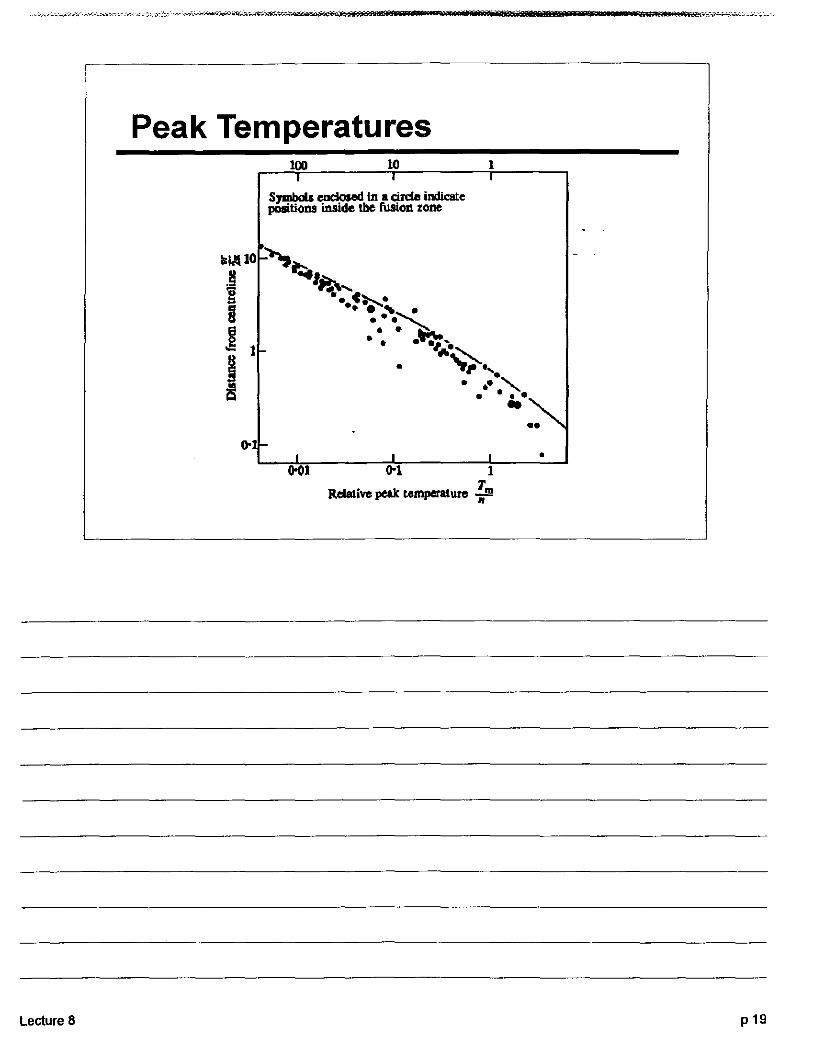
Peak Temperatures100 10 1
SJIIIboIs eoclosed In • dn:1ll indicateposiliOl\ll iIlslde the fuslOll zone
lIklll0 ~i';:,J "Ii!.\-...g •••C~.g • ~.~~~ • e•••"=:....... 1 ."".~j ....... ......l!l ••- "-Q • • ••..
--•
1)001 001 1
lleIative peak umperatute 1'.."
Lecture 8 P 19
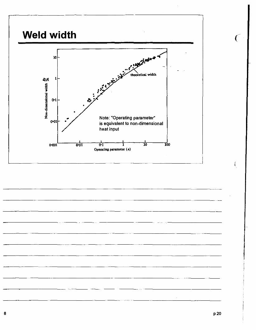
Weld width
10
.'• •,...'I!' thooretical width~..• •
\l:.~o(
,).:
Note: "Operating parameter"is equivalent to non-dimensionalheat input
(
8
0-001 0-01 001 1Operating perameter (n)
10 100
p20

Cooling RatesIe
o measured oooIilll mtes• reciprocal buh lengths
~.;;1
~~~-"..ti ()oJ
.J 0
~ 0
(loOl(lo1 1 10 100
Operating parameter (n)
Lecture 8 p2t
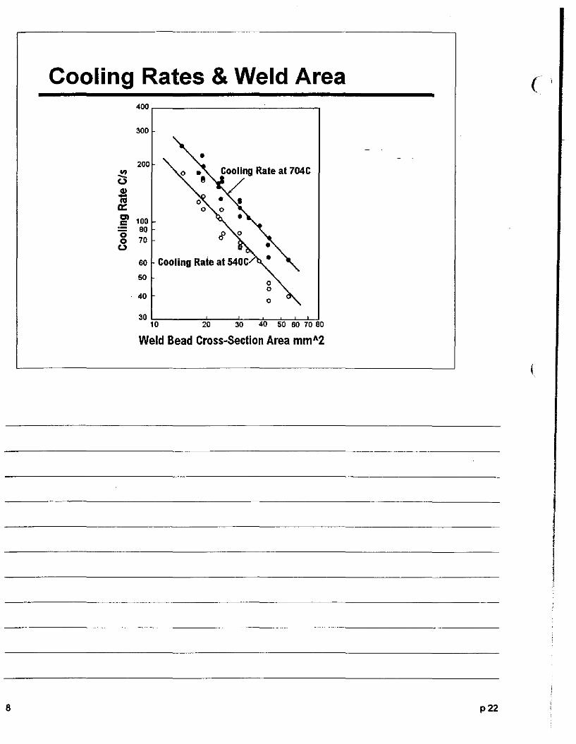
Cooling Rates & Weld Area400 r----------'-----,
300
(
200III
C3
ig' 100
808 70
60
50
40
Cooling Rate at 704C
o
8
30 !-::-----:±--~--t.-__:':::___:!:c_*-:!10 20 30 40 50 60 7080
Weld Bead Cross-Section Area mm A2
p22
(
I
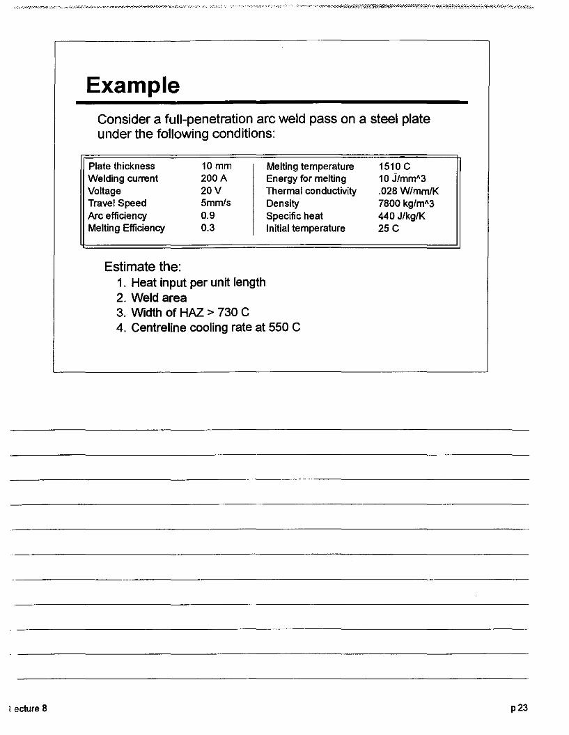
ExampleConsider a full-penetration arc weld pass on a steel plateunder the following conditions:
Plate thicknessWelding currentVoltageTravel SpeedArc efficiencyMelting Efficiency
10 mm200A20V5mmis0.90.3
Melting temperatureEnergy for mellingThermal conductivityDensitySpecific heatInitial temperature
1510 C10 J/mmA3.028W/mmiK7800 kg/mA3440 J/kg/K25C
I eclure 8
Estimate the:1. Heat input per unit length2. Weld area3. Width of HAl > 730 C4. Centreline cooling rate at 550 C
p23
8
Answers (
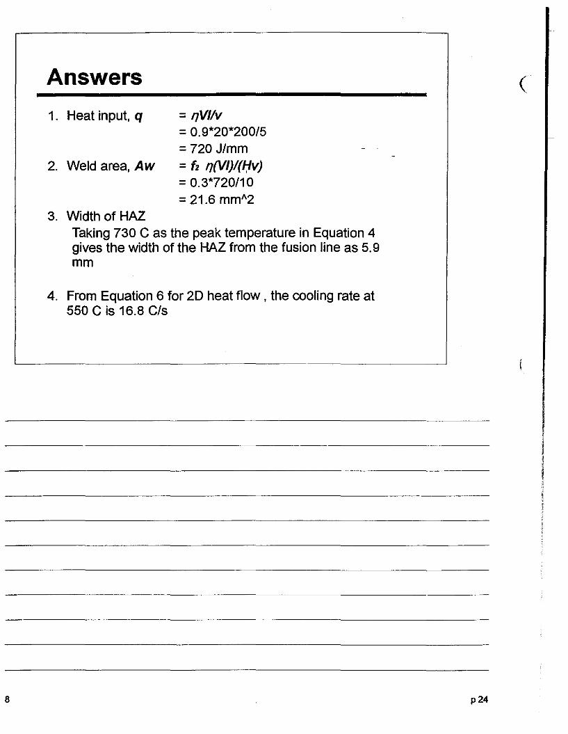
1. Heat input, q = 'lV/iv=0.9*20*200/5=720 J/mm
2. Weld area, Aw =(2 ,,(VI)/(f:lv)= 0.3*720/10=21.6 mmA2
3. Width of HAZTaking 730 C as the peak temperature in Equation 4gives the width of the HAZ from the fusion line as 5.9mm
4. From Equation 6 for 2D heat flow, the cooling rate at550 C is 16.8 CIs
p24


![[ CANDU Poster]a Modified Dedicated Observer Approach to Fault Detection in CANDU Rx](https://img.pdfslide.us/doc/110x75/577cd4391a28ab9e7897f7c3/-candu-postera-modified-dedicated-observer-approach-to-fault-detection-in.jpg)