Embed Size (px)
Citation preview
Operating instructions
EN
Welding machine
Taurus 351-551 Synergic S MM FDG/FDW
099-005341-EW501 Observe additional system documents! 27.01.2016

General instructions
CAUTION
Read the operating instructions!
The operating instructions provide an introduction to the safe use of the products.
• Read the operating instructions for all system components!
• Observe accident prevention regulations!
• Observe all local regulations!
• Confirm with a signature where appropriate.
In the event of queries on installation, commissioning, operation or special conditions at the installation site, or on usage, please contact your sales partner or our customer service department on +49 2680 181-0. A list of authorised sales partners can be found at www.ewm-group.com.
Liability relating to the operation of this equipment is restricted solely to the function of the
equipment. No other form of liability, regardless of type, shall be accepted. This exclusion of
liability shall be deemed accepted by the user on commissioning the equipment.
The manufacturer is unable to monitor whether or not these instructions or the conditions and
methods are observed during installation, operation, usage and maintenance of the equipment.
An incorrectly performed installation can result in material damage and injure persons as a
result. For this reason, we do not accept any responsibility or liability for losses, damages or
costs arising from incorrect installation, improper operation or incorrect usage and maintenance
or any actions connected to this in any way.
© EWM AG · Dr. Günter-Henle-Str. 8 · D-56271 Mündersbach, Germany
The copyright to this document remains the property of the manufacturer.
Reprinting, including extracts, only permitted with written approval.
The content of this document has been prepared and reviewed with all reasonable care. The information
provided is subject to change, errors excepted.
ContentsNotes on the use of these operating instructions
099-005341-EW501
27.01.2016 3
1 Contents
1 Contents .................................................................................................................................................. 3
2 Safety instructions ................................................................................................................................. 5 2.1 Notes on the use of these operating instructions .......................................................................... 5 2.2 Explanation of icons ....................................................................................................................... 6 2.3 General .......................................................................................................................................... 7 2.4 Transport and installation ............................................................................................................ 11
2.4.1 Lifting by crane ............................................................................................................. 12 2.4.2 Ambient conditions ....................................................................................................... 13
2.4.2.1 In operation ................................................................................................... 13 2.4.2.2 Transport and storage ................................................................................... 13
3 Intended use ......................................................................................................................................... 14 3.1 Use and operation solely with the following machines ................................................................ 14 3.2 Applications .................................................................................................................................. 14 3.3 Documents which also apply ....................................................................................................... 15
3.3.1 Warranty ....................................................................................................................... 15 3.3.2 Declaration of Conformity ............................................................................................. 15 3.3.3 Welding in environments with increased electrical hazards ......................................... 15 3.3.4 Service documents (spare parts and circuit diagrams) ................................................ 15 3.3.5 Calibration/Validation ................................................................................................... 15
4 Machine description – quick overview .............................................................................................. 16 4.1 Front view .................................................................................................................................... 16 4.2 Rear view ..................................................................................................................................... 18
5 Design and function ............................................................................................................................. 20 5.1 General ........................................................................................................................................ 20 5.2 Installation .................................................................................................................................... 21 5.3 Machine cooling ........................................................................................................................... 21 5.4 Workpiece lead, general .............................................................................................................. 21 5.5 Notes on the installation of welding current leads ....................................................................... 22 5.6 Welding torch cooling system ...................................................................................................... 24
5.6.1 List of coolants .............................................................................................................. 24 5.6.2 Maximal hose package length ...................................................................................... 24 5.6.3 Adding coolant .............................................................................................................. 25
5.7 Mains connection ......................................................................................................................... 26 5.7.1 Mains configuration ...................................................................................................... 26
5.8 Connecting the intermediate hose package to the power source ............................................... 27 5.9 Shielding gas supply (shielding gas cylinder for welding machine) ............................................. 28
5.9.1 Connection ................................................................................................................... 29 5.10 Aligning the cable resistance ....................................................................................................... 30 5.11 MIG/MAG welding ........................................................................................................................ 32
5.11.1 Connection for workpiece lead ..................................................................................... 32 5.12 TIG welding .................................................................................................................................. 33
5.12.1 Welding torch connection ............................................................................................. 33 5.12.2 Connection for workpiece lead ..................................................................................... 34
5.13 MMA welding ............................................................................................................................... 35 5.13.1 Connecting the electrode holder and workpiece lead .................................................. 35 5.13.2 Voltage reducing device (VRD) .................................................................................... 36
5.14 Remote control ............................................................................................................................. 36 5.15 PC Interfaces ............................................................................................................................... 36
6 Maintenance, care and disposal ......................................................................................................... 37 6.1 General ........................................................................................................................................ 37 6.2 Maintenance work, intervals ........................................................................................................ 37
6.2.1 Daily maintenance tasks .............................................................................................. 37 6.2.1.1 Visual inspection ........................................................................................... 37 6.2.1.2 Functional test ............................................................................................... 37
6.2.2 Monthly maintenance tasks .......................................................................................... 38 6.2.2.1 Visual inspection ........................................................................................... 38
Contents Notes on the use of these operating instructions
4 099-005341-EW501
27.01.2016
6.2.2.2 Functional test ............................................................................................... 38 6.2.3 Annual test (inspection and testing during operation) .................................................. 38
6.3 Disposing of equipment ................................................................................................................ 38 6.3.1 Manufacturer's declaration to the end user .................................................................. 38
6.4 Meeting the requirements of RoHS .............................................................................................. 38
7 Rectifying faults.................................................................................................................................... 39 7.1 Checklist for rectifying faults ........................................................................................................ 39 7.2 Error messages ............................................................................................................................ 40 7.3 Resetting JOBs (welding tasks) to the factory settings ................................................................ 42
7.3.1 Resetting a single JOB ................................................................................................. 42 7.3.2 Resetting all JOBs ........................................................................................................ 43
7.4 Vent coolant circuit ....................................................................................................................... 44
8 Technical data....................................................................................................................................... 45 8.1 Taurus 351 Synergic S MM FDG ................................................................................................. 45 8.2 Taurus 351 Synergic S MM VRD FDG ........................................................................................ 46 8.3 Taurus 351 Synergic S MM FDW ................................................................................................ 47 8.4 Taurus 401 Synergic S MM FDG ................................................................................................. 48 8.5 Taurus 401 Synergic S MM FDW ................................................................................................ 49 8.6 Taurus 451 Synergic S MM FDG ................................................................................................. 50 8.7 Taurus 451 Synergic S MM FDW ................................................................................................ 51 8.8 Taurus 551 Synergic S MM FDG ................................................................................................. 52 8.9 Taurus 551 Synergic S MM FDW ................................................................................................ 53
9 Accessories .......................................................................................................................................... 54 9.1 System components ..................................................................................................................... 54 9.2 General accessories .................................................................................................................... 54 9.3 Remote control/connecting and extension cable ......................................................................... 54
9.3.1 7-pole connection ......................................................................................................... 54 9.4 Options ......................................................................................................................................... 55
10 Appendix A ............................................................................................................................................ 56 10.1 Overview of EWM branches......................................................................................................... 56
Safety instructionsNotes on the use of these operating instructions
099-005341-EW501
27.01.2016 5
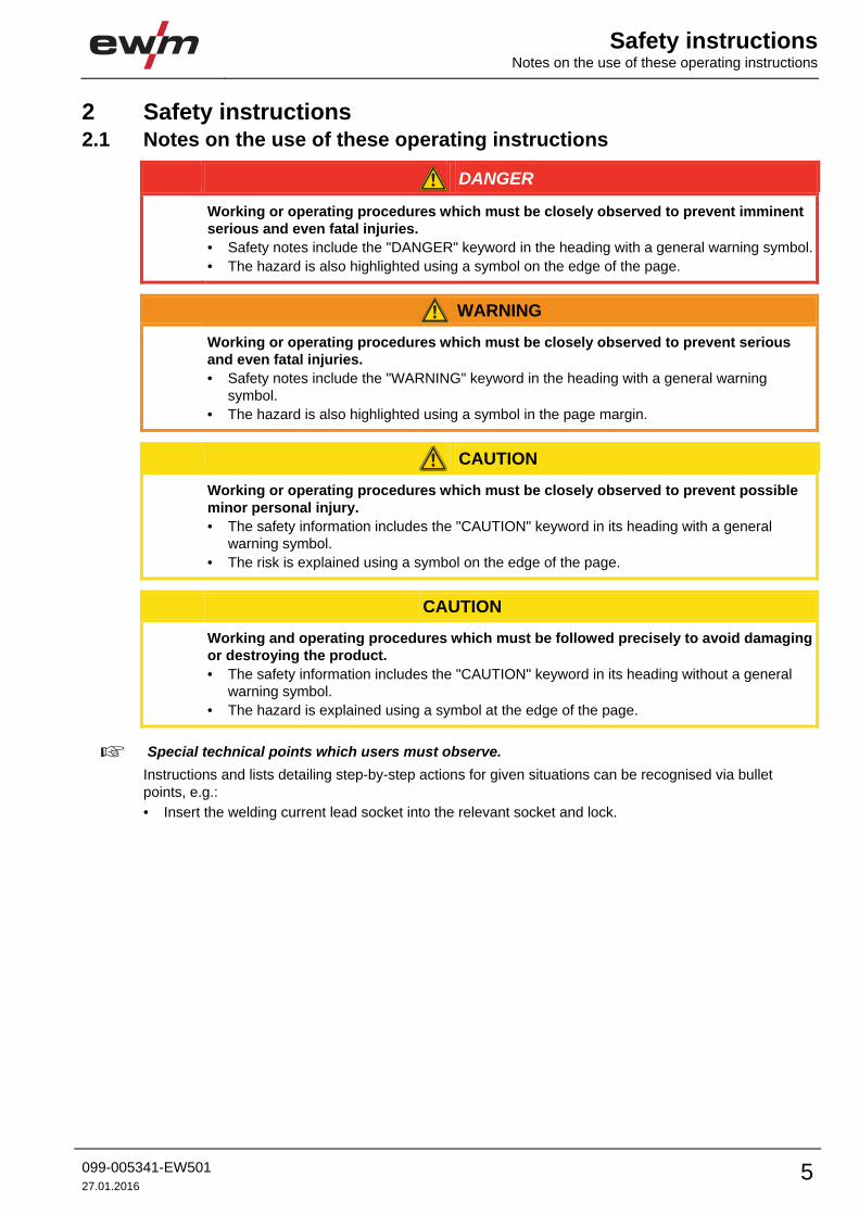
2 Safety instructions 2.1 Notes on the use of these operating instructions
DANGER
Working or operating procedures which must be closely observed to prevent imminent
serious and even fatal injuries.
• Safety notes include the "DANGER" keyword in the heading with a general warning symbol.
• The hazard is also highlighted using a symbol on the edge of the page.
WARNING
Working or operating procedures which must be closely observed to prevent serious
and even fatal injuries.
• Safety notes include the "WARNING" keyword in the heading with a general warning
symbol.
• The hazard is also highlighted using a symbol in the page margin.
CAUTION
Working or operating procedures which must be closely observed to prevent possible
minor personal injury.
• The safety information includes the "CAUTION" keyword in its heading with a general
warning symbol.
• The risk is explained using a symbol on the edge of the page.
CAUTION
Working and operating procedures which must be followed precisely to avoid damaging
or destroying the product.
• The safety information includes the "CAUTION" keyword in its heading without a general
warning symbol.
• The hazard is explained using a symbol at the edge of the page.
Special technical points which users must observe.
Instructions and lists detailing step-by-step actions for given situations can be recognised via bullet
points, e.g.:
• Insert the welding current lead socket into the relevant socket and lock.

Safety instructions Explanation of icons
6 099-005341-EW501
27.01.2016
2.2 Explanation of icons
Symbol Description
Special technical points which users must observe.
Correct
Wrong
Press
Do not press
Press and keep pressed
Turn
Switch
Switch off machine
Switch on machine
ENTER enter the menu
NAVIGATION Navigating in the menu
EXIT Exit the menu
Time display (example: wait 4s/press)
Interruption in the menu display (other setting options possible)
Tool not required/do not use
Tool required/use
l
0
l
0
Safety instructionsGeneral
099-005341-EW501
27.01.2016 7
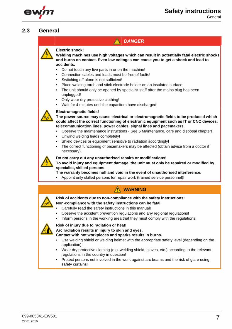
2.3 General
DANGER
Electric shock!
Welding machines use high voltages which can result in potentially fatal electric shocks
and burns on contact. Even low voltages can cause you to get a shock and lead to
accidents.
• Do not touch any live parts in or on the machine!
• Connection cables and leads must be free of faults!
• Switching off alone is not sufficient!
• Place welding torch and stick electrode holder on an insulated surface!
• The unit should only be opened by specialist staff after the mains plug has been
unplugged!
• Only wear dry protective clothing!
• Wait for 4 minutes until the capacitors have discharged!
Electromagnetic fields!
The power source may cause electrical or electromagnetic fields to be produced which
could affect the correct functioning of electronic equipment such as IT or CNC devices,
telecommunication lines, power cables, signal lines and pacemakers.
• Observe the maintenance instructions - See 6 Maintenance, care and disposal chapter!
• Unwind welding leads completely!
• Shield devices or equipment sensitive to radiation accordingly!
• The correct functioning of pacemakers may be affected (obtain advice from a doctor if
necessary).
Do not carry out any unauthorised repairs or modifications!
To avoid injury and equipment damage, the unit must only be repaired or modified by
specialist, skilled persons!
The warranty becomes null and void in the event of unauthorised interference.
• Appoint only skilled persons for repair work (trained service personnel)!
WARNING
Risk of accidents due to non-compliance with the safety instructions!
Non-compliance with the safety instructions can be fatal!
• Carefully read the safety instructions in this manual!
• Observe the accident prevention regulations and any regional regulations!
• Inform persons in the working area that they must comply with the regulations!
Risk of injury due to radiation or heat!
Arc radiation results in injury to skin and eyes.
Contact with hot workpieces and sparks results in burns.
• Use welding shield or welding helmet with the appropriate safety level (depending on the
application)!
• Wear dry protective clothing (e.g. welding shield, gloves, etc.) according to the relevant
regulations in the country in question!
• Protect persons not involved in the work against arc beams and the risk of glare using
safety curtains!

Safety instructions General
8 099-005341-EW501
27.01.2016
WARNING
Explosion risk!
Apparently harmless substances in closed containers may generate excessive pressure
when heated.
• Move containers with inflammable or explosive liquids away from the working area!
• Never heat explosive liquids, dusts or gases by welding or cutting!
Smoke and gases!
Smoke and gases can lead to breathing difficulties and poisoning. In addition, solvent
vapour (chlorinated hydrocarbon) may be converted into poisonous phosgene due to
the ultraviolet radiation of the arc!
• Ensure that there is sufficient fresh air!
• Keep solvent vapour away from the arc beam field!
• Wear suitable breathing apparatus if appropriate!
Fire hazard!
Flames may arise as a result of the high temperatures, stray sparks, glowing-hot parts
and hot slag produced during the welding process.
Stray welding currents can also result in flames forming!
• Check for fire hazards in the working area!
• Do not carry any easily flammable objects such as matches or lighters.
• Keep appropriate fire extinguishing equipment to hand in the working area!
• Thoroughly remove any residue of flammable substances from the workpiece before
starting welding.
• Only continue work on welded workpieces once they have cooled down.
Do not allow to come into contact with flammable material!
• Connect welding leads correctly!
Danger when coupling multiple power sources!
Coupling multiple power sources in parallel or in series has to be carried out by
qualified personnel and in accordance with the manufacturer's guidelines. Before
bringing the power sources into service for arc welding operations, a test has to verify
that they cannot exceed the maximum allowed open circuit voltage.
• Connection of the machine may be carried out by qualified personnel only!
• When decommissioning individual power sources, all mains and welding current leads have
to be safely disconnected from the welding system as a whole. (Danger due to inverse
voltages!)
• Do not couple welding machines with pole reversing switch (PWS series) or machines for
AC welding, as a minor error in operation can cause the welding voltages to be combined.
CAUTION
Noise exposure!
Noise exceeding 70 dBA can cause permanent hearing damage!
• Wear suitable ear protection!
• Persons located within the working area must wear suitable ear protection!
Safety instructionsGeneral
099-005341-EW501
27.01.2016 9
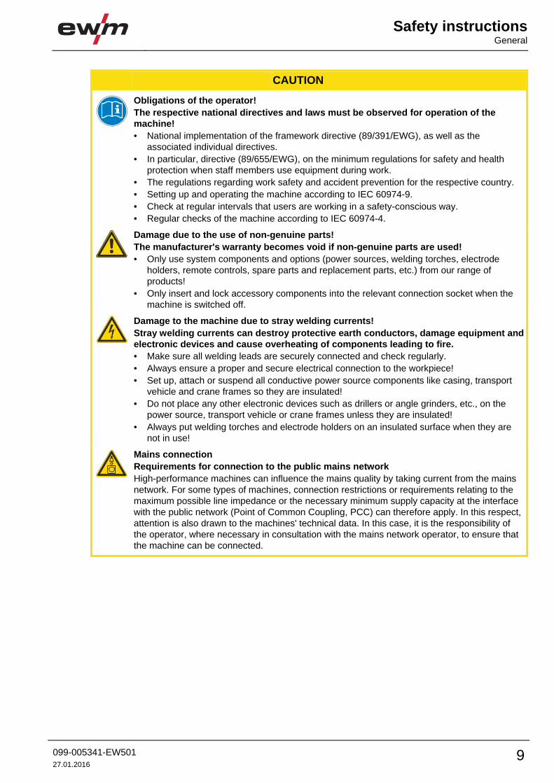
CAUTION
Obligations of the operator!
The respective national directives and laws must be observed for operation of the
machine!
• National implementation of the framework directive (89/391/EWG), as well as the
associated individual directives.
• In particular, directive (89/655/EWG), on the minimum regulations for safety and health
protection when staff members use equipment during work.
• The regulations regarding work safety and accident prevention for the respective country.
• Setting up and operating the machine according to IEC 60974-9.
• Check at regular intervals that users are working in a safety-conscious way.
• Regular checks of the machine according to IEC 60974-4.
Damage due to the use of non-genuine parts!
The manufacturer's warranty becomes void if non-genuine parts are used!
• Only use system components and options (power sources, welding torches, electrode
holders, remote controls, spare parts and replacement parts, etc.) from our range of
products!
• Only insert and lock accessory components into the relevant connection socket when the
machine is switched off.
Damage to the machine due to stray welding currents!
Stray welding currents can destroy protective earth conductors, damage equipment and
electronic devices and cause overheating of components leading to fire.
• Make sure all welding leads are securely connected and check regularly.
• Always ensure a proper and secure electrical connection to the workpiece!
• Set up, attach or suspend all conductive power source components like casing, transport
vehicle and crane frames so they are insulated!
• Do not place any other electronic devices such as drillers or angle grinders, etc., on the
power source, transport vehicle or crane frames unless they are insulated!
• Always put welding torches and electrode holders on an insulated surface when they are
not in use!
Mains connection
Requirements for connection to the public mains network
High-performance machines can influence the mains quality by taking current from the mains
network. For some types of machines, connection restrictions or requirements relating to the
maximum possible line impedance or the necessary minimum supply capacity at the interface
with the public network (Point of Common Coupling, PCC) can therefore apply. In this respect,
attention is also drawn to the machines' technical data. In this case, it is the responsibility of
the operator, where necessary in consultation with the mains network operator, to ensure that
the machine can be connected.
Safety instructions General
10 099-005341-EW501
27.01.2016
CAUTION
EMC Machine Classification
In accordance with IEC 60974-10, welding machines are grouped in two electromagnetic
compatibility classes - See 8 Technical data chapter:
Class A machines are not intended for use in residential areas where the power supply comes
from the low-voltage public mains network. When ensuring the electromagnetic compatibility of
class A machines, difficulties can arise in these areas due to interference not only in the supply
lines but also in the form of radiated interference.
Class B machines fulfil the EMC requirements in industrial as well as residential areas,
including residential areas connected to the low-voltage public mains network.
Setting up and operating
When operating arc welding systems, in some cases, electro-magnetic interference can occur
although all of the welding machines comply with the emission limits specified in the standard.
The user is responsible for any interference caused by welding.
In order to evaluate any possible problems with electromagnetic compatibility in the
surrounding area, the user must consider the following: (see also EN 60974-10 Appendix A)
• Mains, control, signal and telecommunication lines
• Radios and televisions
• Computers and other control systems
• Safety equipment
• The health of neighbouring persons, especially if they have a pacemaker or wear a hearing
aid
• Calibration and measuring equipment
• The immunity to interference of other equipment in the surrounding area
• The time of day at which the welding work must be carried out
Recommendations for reducing interference emission
• Mains connection, e.g. additional mains filter or shielding with a metal tube
• Maintenance of the arc welding equipment
• Welding leads should be as short as possible and run closely together along the ground
• Potential equalization
• Earthing of the workpiece. In cases where it is not possible to earth the workpiece directly,
it should be connected by means of suitable capacitors.
• Shielding from other equipment in the surrounding area or the entire welding system
Safety instructionsTransport and installation
099-005341-EW501
27.01.2016 11
2.4 Transport and installation
WARNING
Incorrect handling of shielding gas cylinders!
Incorrect handling of shielding gas cylinders can result in serious and even fatal injury.
• Observe the instructions from the gas manufacturer and in any relevant regulations
concerning the use of compressed air!
• Place shielding gas cylinders in the holders provided for them and secure with fixing
devices.
• Avoid heating the shielding gas cylinder!
CAUTION
Risk of tipping!
There is a risk of the machine tipping over and injuring persons or being damaged itself
during movement and set up. Tilt resistance is guaranteed up to an angle of 10°
(according to EN 60974-A2).
• Set up and transport the machine on level, solid ground!
• Secure add-on parts using suitable equipment!
• Replace damaged wheels and their fixing elements!
• Fix external wire feed units during transport (avoid uncontrolled rotation)!
Damage due to supply lines not being disconnected!
During transport, supply lines which have not been disconnected (mains supply leads,
control leads, etc.) may cause hazards such as connected equipment tipping over and
injuring persons!
• Disconnect supply lines!
CAUTION
Equipment damage when not operated in an upright position!
The units are designed for operation in an upright position!
Operation in non-permissible positions can cause equipment damage.
• Only transport and operate in an upright position!

Safety instructions Transport and installation
12 099-005341-EW501
27.01.2016
2.4.1 Lifting by crane
WARNING
Risk of injury during lifting by crane!
When lifting the machine by crane, persons may be severely injured by falling machines
or mount-on components.
• Simultaneous lifting of system components such as power source, wire
feeder or cooling unit without suitable crane components is not
allowed. Each system component has to be lifted separately!
• Remove any supply leads and accessories before lifting by crane (e.g.
hose package, wire spool, shielding gas cylinder, toolbox, wire feeder,
remote control,etc.)!)
• Properly close and lock all casing covers and protective caps before
lifting by crane!
• Use the correct number of hoisting equipment of the right size in the
correct position! Observe craning principle (see figure)!
• For machines with lifting eyes: always lift all lifting eyes simultaneously!
• When using retrofitted craning frames etc.: always use at least two
lifting points positioned as far apart as possible – observe option
description.
• Avoid any jerky movements!
• Ensure that the load is distributed evenly! • Use chain hoists and
chain slings of the same length only!
• Stay outside the danger zone underneath the machine!
• Observe the regulations regarding occupational safety and accident
prevention for the respective country.
Craning principle
Risk of injury due to unsuitable lifting eye!
In case of improper use of lifting eyes or the use of unsuitable lifting eyes, persons can
be seriously damaged by falling equipment or add-on components!
• The lifting eye must be completely screwed in!
• The lifting eye must be positioned flat onto and in full contact with the supporting surfaces!
• Check that the lifting eyes are securely fastened before use and check for any damage
(corrosion, deformation)!
• Do not use or screw in damaged lifting eyes!
• Avoid lateral loading of the lifting eyes!
min
. 1m
min. 75°

Safety instructionsTransport and installation
099-005341-EW501
27.01.2016 13
2.4.2 Ambient conditions
CAUTION
Installation site!
The machine must not be operated in the open air and must only be set up and
operated on a suitable, stable and level base!
• The operator must ensure that the ground is non-slip and level, and provide sufficient
lighting for the place of work.
• Safe operation of the machine must be guaranteed at all times.
CAUTION
Equipment damage due to dirt accumulation!
Unusually high quantities of dust, acid, corrosive gases or substances may damage the
equipment.
• Avoid high volumes of smoke, vapour, oil vapour and grinding dust!
• Avoid ambient air containing salt (sea air)!
Non-permissible ambient conditions!
Insufficient ventilation results in a reduction in performance and equipment damage.
• Observe the ambient conditions!
• Keep the cooling air inlet and outlet clear!
• Observe the minimum distance of 0.5 m from obstacles!
2.4.2.1 In operation
Temperature range of the ambient air:
• -25 °C to +40 °C
Relative air humidity:
• Up to 50% at 40 °C
• Up to 90% at 20 °C
2.4.2.2 Transport and storage
Storage in an enclosed space, temperature range of the ambient air:
• -30 °C to +70 °C
Relative air humidity
• Up to 90% at 20 °C
Intended use Use and operation solely with the following machines
14 099-005341-EW501
27.01.2016
3 Intended use
WARNING
Hazards due to improper usage!
Hazards may arise for persons, animals and material objects if the equipment is not
used correctly. No liability is accepted for any damages arising from improper usage!
• The equipment must only be used in line with proper usage and by trained or expert staff!
• Do not modify or convert the equipment improperly!
Arc welding machine for standard and pulsed gas-shielded metal-arc welding with TIG welding and lift arc
(touch starting) or MMA welding as secondary process. It may be possible to expand the functionality by
using accessories (see the documentation in the relevant chapter).
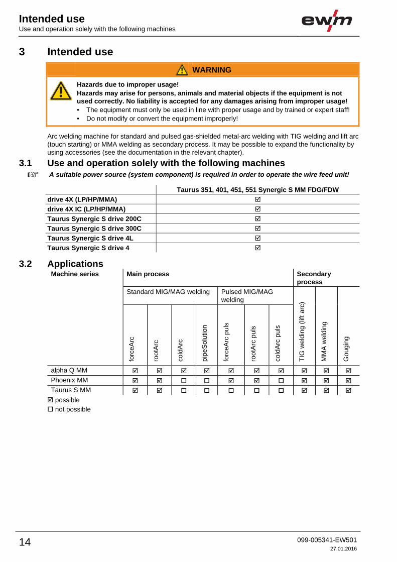
3.1 Use and operation solely with the following machines
A suitable power source (system component) is required in order to operate the wire feed unit!
Taurus 351, 401, 451, 551 Synergic S MM FDG/FDW
drive 4X (LP/HP/MMA)
drive 4X IC (LP/HP/MMA)
Taurus Synergic S drive 200C
Taurus Synergic S drive 300C
Taurus Synergic S drive 4L
Taurus Synergic S drive 4
3.2 Applications Machine series Main process Secondary
process
Standard MIG/MAG welding Pulsed MIG/MAG
welding T
IG w
eld
ing (
lift arc
)
MM
A w
eld
ing
Go
ug
ing
forc
eA
rc
rootA
rc
co
ldA
rc
pip
eS
olu
tion
forc
eA
rc p
uls
rootA
rc p
uls
co
ldA
rc p
uls
alpha Q MM
Phoenix MM
Taurus S MM
possible
not possible
Intended useDocuments which also apply
099-005341-EW501
27.01.2016 15
3.3 Documents which also apply 3.3.1 Warranty
For more information refer to the "Warranty registration" brochure supplied and our information regarding warranty, maintenance and testing at www.ewm-group.com!
3.3.2 Declaration of Conformity
The designated machine conforms to EC Directives and standards in terms of its design
and construction:
• EC Low Voltage Directive (2006/95/EC),
• EC EMC Directive (2004/108/EC),
This declaration shall become null and void in the event of unauthorised modifications, improperly
conducted repairs, non-observance of the deadlines for the repetition test and / or non-permitted
conversion work not specifically authorised by the manufacturer.
The original copy of the declaration of conformity is enclosed with the unit.
3.3.3 Welding in environments with increased electrical hazards
In compliance with IEC / DIN EN 60974, VDE 0544 the machines can be used in
environments with an increased electrical hazard.
3.3.4 Service documents (spare parts and circuit diagrams)
DANGER
Do not carry out any unauthorised repairs or modifications!
To avoid injury and equipment damage, the unit must only be repaired or modified by
specialist, skilled persons!
The warranty becomes null and void in the event of unauthorised interference.
• Appoint only skilled persons for repair work (trained service personnel)!
Original copies of the circuit diagrams are enclosed with the unit.
Spare parts can be obtained from the relevant authorised dealer.
3.3.5 Calibration/Validation We hereby confirm that this machine has been tested using calibrated measuring equipment, as
stipulated in IEC/EN 60974, ISO/EN 17662, EN 50504, and complies with the admissible tolerances.
Recommended calibration interval: 12 months
Machine description – quick overview Front view
16 099-005341-EW501
27.01.2016
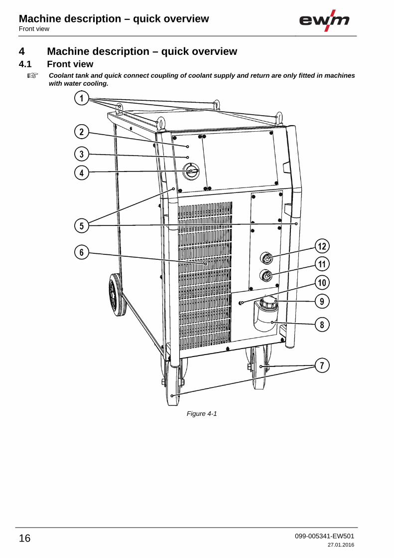
4 Machine description – quick overview 4.1 Front view
Coolant tank and quick connect coupling of coolant supply and return are only fitted in machines with water cooling.
Figure 4-1
Machine description – quick overviewFront view
099-005341-EW501
27.01.2016 17
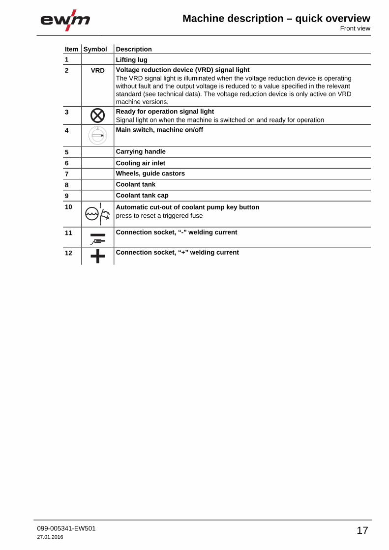
Item Symbol Description 0
1 Lifting lug
2 VRD Voltage reduction device (VRD) signal light
The VRD signal light is illuminated when the voltage reduction device is operating
without fault and the output voltage is reduced to a value specified in the relevant
standard (see technical data). The voltage reduction device is only active on VRD
machine versions.
3
Ready for operation signal light
Signal light on when the machine is switched on and ready for operation
4
Main switch, machine on/off
5 Carrying handle
6 Cooling air inlet
7 Wheels, guide castors
8 Coolant tank
9 Coolant tank cap
10
Automatic cut-out of coolant pump key button
press to reset a triggered fuse
11
Connection socket, “-” welding current
12
Connection socket, “+” welding current
l
0
Machine description – quick overview Rear view
18 099-005341-EW501
27.01.2016
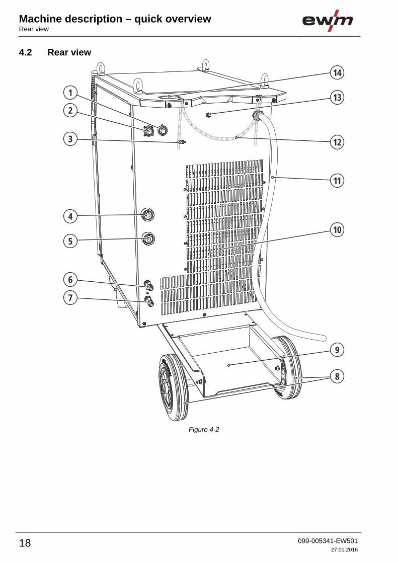
4.2 Rear view
6
7
4
3
2
1
10
5
9
11
12
8
13
14
Figure 4-2
Machine description – quick overviewRear view
099-005341-EW501
27.01.2016 19
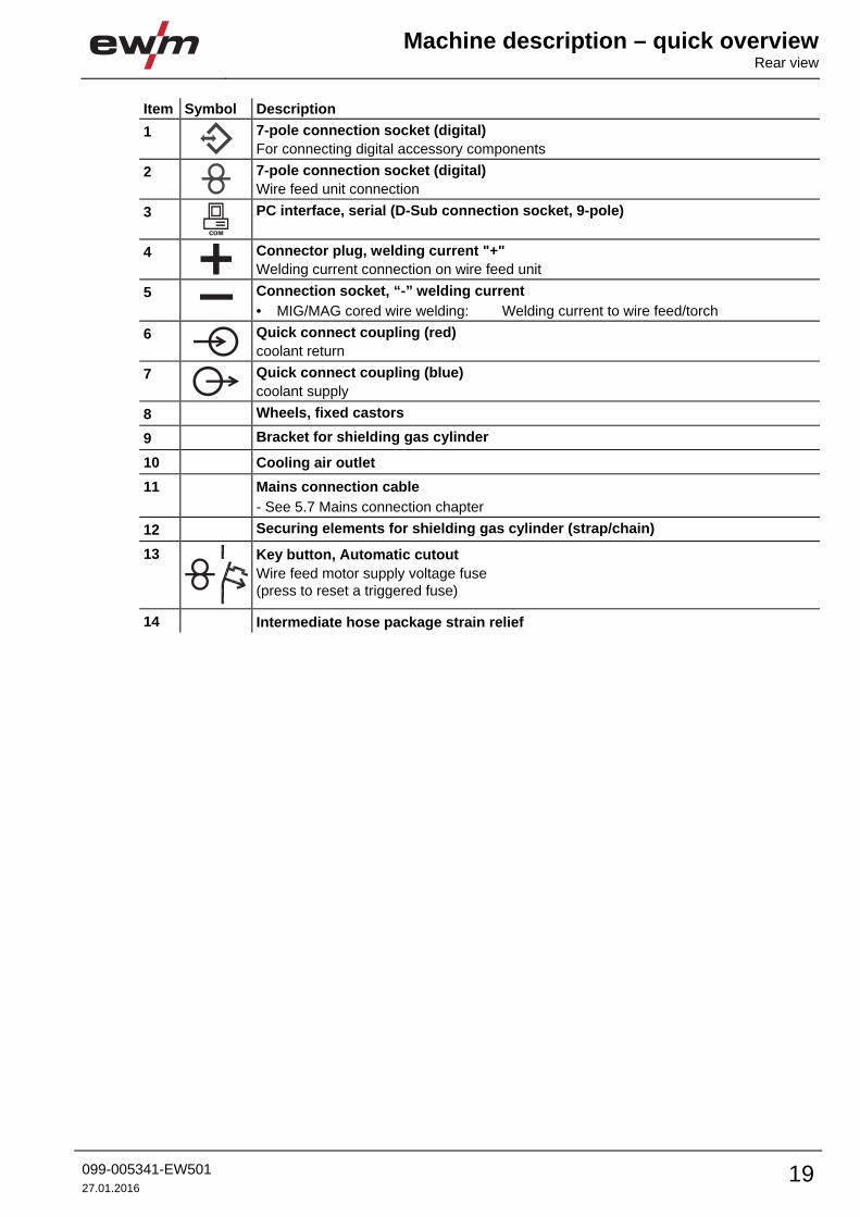
Item Symbol Description 0
1
7-pole connection socket (digital)
For connecting digital accessory components
2
7-pole connection socket (digital)
Wire feed unit connection
3
PC interface, serial (D-Sub connection socket, 9-pole)
4
Connector plug, welding current "+"
Welding current connection on wire feed unit
5 Connection socket, “-” welding current
• MIG/MAG cored wire welding: Welding current to wire feed/torch
6
Quick connect coupling (red)
coolant return
7
Quick connect coupling (blue)
coolant supply
8 Wheels, fixed castors
9 Bracket for shielding gas cylinder
10 Cooling air outlet
11 Mains connection cable
- See 5.7 Mains connection chapter
12 Securing elements for shielding gas cylinder (strap/chain)
13
Key button, Automatic cutout
Wire feed motor supply voltage fuse
(press to reset a triggered fuse)
14 Intermediate hose package strain relief
COM
Design and function General
20 099-005341-EW501
27.01.2016
5 Design and function 5.1 General
WARNING
Risk of injury from electric shock!
Contact with live parts, e.g. welding current sockets, is potentially fatal!
• Follow safety instructions on the opening pages of the operating instructions.
• Commissioning may only be carried out by persons who have the relevant expertise of
working with arc welding machines!
• Connection and welding leads (e.g. electrode holder, welding torch, workpiece lead,
interfaces) may only be connected when the machine is switched off!
CAUTION
Insulate the arc welder from welding voltage!
Not all active parts of the welding current circuit can be shielded from direct contact. To
avoid any associated risks it is vital for the welder to adhere to the relevant safety
regulations. Even low voltages can cause a shock and lead to accidents.
• Wear dry and undamaged protective clothing (shoes with rubber soles/welder's gloves
made from leather without any studs or braces)!
• Avoid direct contact with non-insulated connection sockets or connectors!
• Always place torches and electrode holders on an insulated surface!
Risk of burns on the welding current connection!
If the welding current connections are not locked, connections and leads heat up and
can cause burns, if touched!
• Check the welding current connections every day and lock by turning in clockwise direction,
if necessary.
Risk of injury due to moving parts!
The wire feeders are equipped with moving parts, which can trap hands, hair, clothing
or tools and thus injure persons!
• Do not reach into rotating or moving parts or drive components!
• Keep casing covers or protective caps closed during operation!
Risk of injury due to welding wire escaping in an unpredictable manner!
Welding wire can be conveyed at very high speeds and, if conveyed incorrectly, may
escape in an uncontrolled manner and injure persons!
• Before mains connection, set up the complete wire guide system from the wire spool to the
welding torch!
• Remove the pressure rollers from the wire feeder if no welding torch is fitted!
• Check wire guide at regular intervals!
• Keep all casing covers or protective caps closed during operation!
Risk from electrical current!
If welding is carried out alternately using different methods and if a welding torch and
an electrode holder remain connected to the machine, the open-circuit/welding voltage
is applied simultaneously on all cables.
• The torch and the electrode holder should therefore always be placed on an insulated
surface before starting work and during breaks.
Design and functionInstallation
099-005341-EW501
27.01.2016 21
CAUTION
Damage due to incorrect connection!
Accessory components and the power source itself can be damaged by incorrect
connection!
• Only insert and lock accessory components into the relevant connection socket when the
machine is switched off.
• Comprehensive descriptions can be found in the operating instructions for the relevant
accessory components.
• Accessory components are detected automatically after the power source is switched on.
Using protective dust caps!
Protective dust caps protect the connection sockets and therefore the machine against
dirt and damage.
• The protective dust cap must be fitted if there is no accessory component being operated
on that connection.
• The cap must be replaced if faulty or if lost!
Observe documentation of other system components when connecting!
5.2 Installation
CAUTION
Installation site!
The machine must not be operated in the open air and must only be set up and
operated on a suitable, stable and level base!
• The operator must ensure that the ground is non-slip and level, and provide sufficient
lighting for the place of work.
• Safe operation of the machine must be guaranteed at all times.
5.3 Machine cooling To obtain an optimal duty cycle from the power components, the following precautions should be
observed:
• Ensure that the working area is adequately ventilated.
• Do not obstruct the air inlets and outlets of the machine.
• Do not allow metal parts, dust or other objects to get into the machine.
5.4 Workpiece lead, general
CAUTION
Risk of burns due to incorrect connection of the workpiece lead!
Paint, rust and dirt on the connection restrict the power flow and may lead to stray
welding currents.
Stray welding currents may cause fires and injuries!
• Clean the connections!
• Fix the workpiece lead securely!
• Do not use structural parts of the workpiece as a return lead for the welding current!
• Take care to ensure faultless power connections!
Design and function Notes on the installation of welding current leads
22 099-005341-EW501
27.01.2016
5.5 Notes on the installation of welding current leads
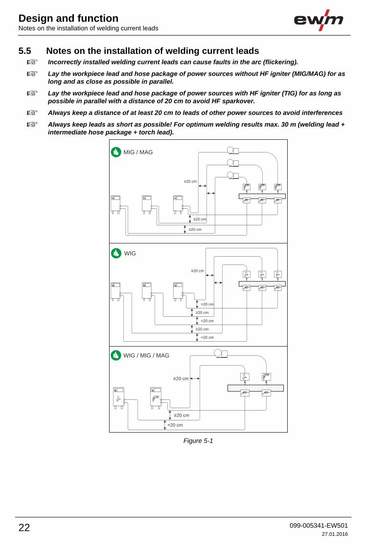
Incorrectly installed welding current leads can cause faults in the arc (flickering).
Lay the workpiece lead and hose package of power sources without HF igniter (MIG/MAG) for as long and as close as possible in parallel.
Lay the workpiece lead and hose package of power sources with HF igniter (TIG) for as long as possible in parallel with a distance of 20 cm to avoid HF sparkover.
Always keep a distance of at least 20 cm to leads of other power sources to avoid interferences
Always keep leads as short as possible! For optimum welding results max. 30 m (welding lead + intermediate hose package + torch lead).
≈20 cm
≥20 cm
≥20 cm
WIG / MIG / MAG
≥20 cm
≈20 cm
≥20 cm
≈20 cm
≥20 cm
≈20 cm
WIG
≥20 cm
≥20 cm
≥20 cm
MIG / MAG
Figure 5-1
Design and functionNotes on the installation of welding current leads
099-005341-EW501
27.01.2016 23
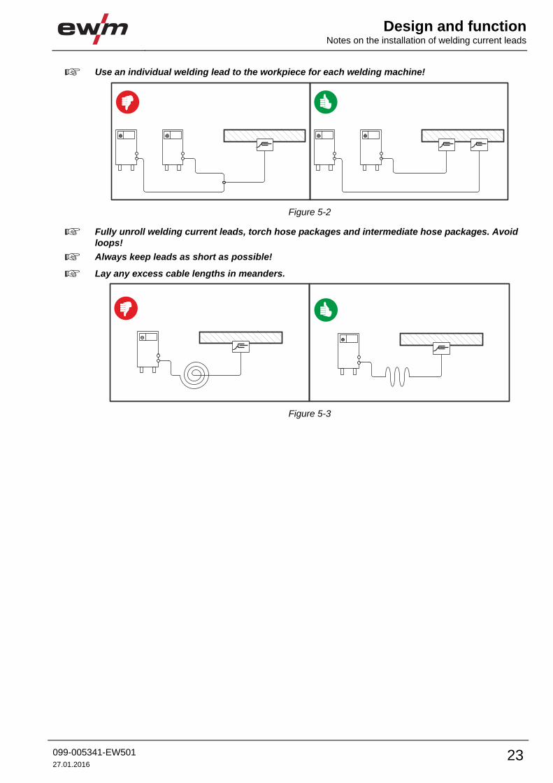
Use an individual welding lead to the workpiece for each welding machine!
Figure 5-2
Fully unroll welding current leads, torch hose packages and intermediate hose packages. Avoid loops!
Always keep leads as short as possible!
Lay any excess cable lengths in meanders.
Figure 5-3

Design and function Welding torch cooling system
24 099-005341-EW501
27.01.2016
5.6 Welding torch cooling system
CAUTION
Coolant mixtures!
Mixtures with other liquids or the use of unsuitable coolants result in material damage
and renders the manufacturer's warranty void!
• Only use the coolant described in this manual (overview of coolants).
• Do not mix different coolants.
• When changing the coolant, the entire volume of liquid must be changed.
Insufficient frost protection in the welding torch coolant!
Depending on the ambient conditions, different liquids are used for cooling the welding
torch - See 5.6.1 List of coolants chapter.
Coolants with frost protection (KF 37E or KF 23E) must be checked regularly to ensure
that the frost protection is adequate to prevent damage to the machine or the accessory
components.
• The coolant must be checked for adequate frost protection with the TYP 1 frost protection
tester .
• Replace coolant as necessary if frost protection is inadequate!
The disposal of coolant must be carried out according to official regulations and observing the relevant safety data sheets (German waste code number: 70104)! Coolant must not be disposed of together with household waste. Coolant must not be discharged into the sewerage system. Recommended cleaning agent: water, if necessary with cleaning agent added.
5.6.1 List of coolants The following coolants may be used - See 9 Accessories chapter:
Coolant Temperature range
KF 23E (Standard) -10 °C to +40 °C
KF 37E -20 °C to +10 °C
5.6.2 Maximal hose package length Pump 3.5 bar Pump 4.5 bar
Machines with or without separate wire feeder 30 m 60 m
Compact machines with additional intermediate
drive (example. miniDrive) 20 m 30 m
Machines with separate wire feeder and additional
intermediate drive (example: miniDrive) 20 m 60 m
Data as a rule refer to the entire hose package length
including welding torch. The pump output is shown on the type plate (parameter: Pmax).
Pump 3.5 bar: Pmax = 0.35 MPa (3.5 bar)
Pump 4.5 bar: Pmax = 0.45 MPa (4.5 bar)
Design and functionWelding torch cooling system
099-005341-EW501
27.01.2016 25
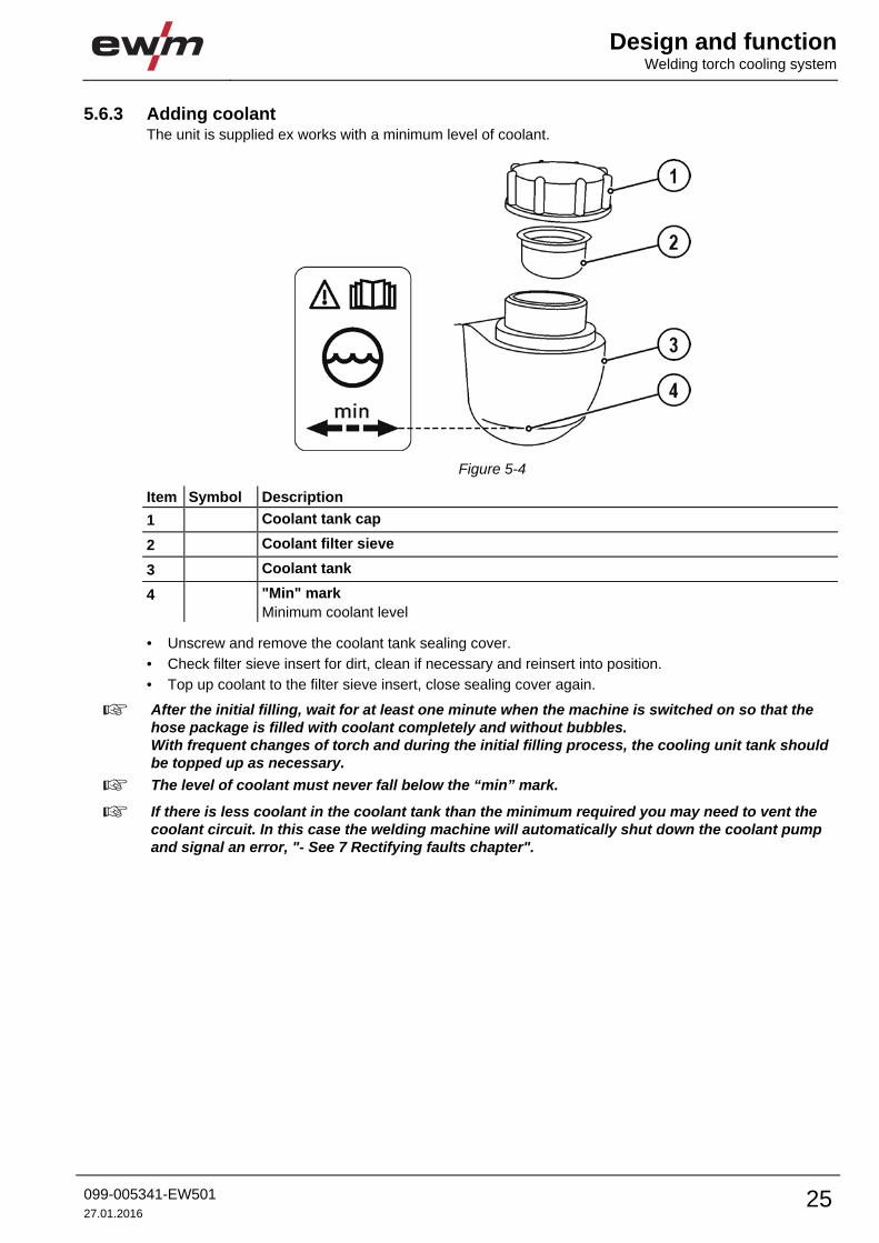
5.6.3 Adding coolant The unit is supplied ex works with a minimum level of coolant.
Figure 5-4
Item Symbol Description 0
1 Coolant tank cap
2 Coolant filter sieve
3 Coolant tank
4 "Min" mark
Minimum coolant level
• Unscrew and remove the coolant tank sealing cover.
• Check filter sieve insert for dirt, clean if necessary and reinsert into position.
• Top up coolant to the filter sieve insert, close sealing cover again.
After the initial filling, wait for at least one minute when the machine is switched on so that the hose package is filled with coolant completely and without bubbles. With frequent changes of torch and during the initial filling process, the cooling unit tank should be topped up as necessary.
The level of coolant must never fall below the “min” mark.
If there is less coolant in the coolant tank than the minimum required you may need to vent the coolant circuit. In this case the welding machine will automatically shut down the coolant pump and signal an error, "- See 7 Rectifying faults chapter".
Design and function Mains connection
26 099-005341-EW501
27.01.2016
5.7 Mains connection
DANGER
Hazard caused by improper mains connection!
An improper mains connection can cause injuries or damage property!
• Only use machine with a plug socket that has a correctly fitted protective conductor.
• If a mains plug must be fitted, this may only be carried out by an electrician in accordance
with the relevant national provisions or regulations!
• Mains plug, socket and lead must be checked regularly by an electrician!
• When operating the generator always ensure it is earthed as stated in the operating
instructions. The resulting network has to be suitable for operating devices according to
protection class 1.
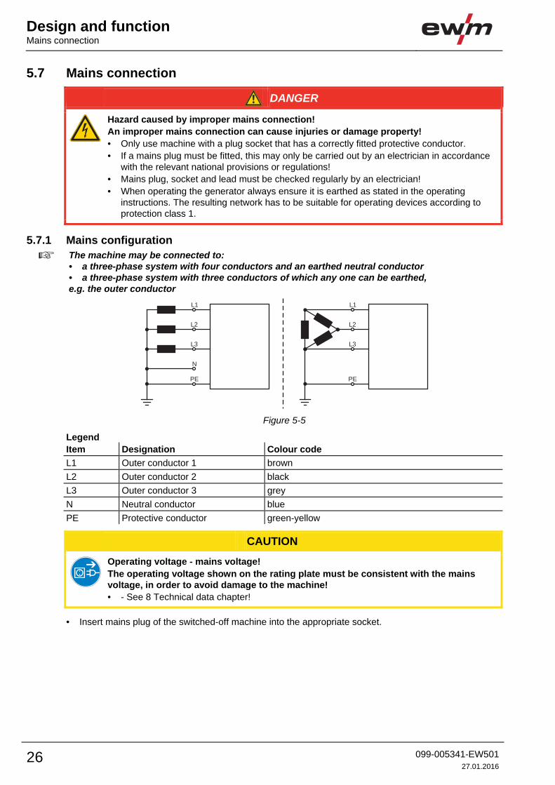
5.7.1 Mains configuration
The machine may be connected to: • a three-phase system with four conductors and an earthed neutral conductor • a three-phase system with three conductors of which any one can be earthed, e.g. the outer conductor
L1 L1
L3 L3
N
L2 L2
PE PE
Figure 5-5
Legend
Item Designation Colour code
L1 Outer conductor 1 brown
L2 Outer conductor 2 black
L3 Outer conductor 3 grey
N Neutral conductor blue
PE Protective conductor green-yellow
CAUTION
Operating voltage - mains voltage!
The operating voltage shown on the rating plate must be consistent with the mains
voltage, in order to avoid damage to the machine!
• - See 8 Technical data chapter!
• Insert mains plug of the switched-off machine into the appropriate socket.

Design and functionConnecting the intermediate hose package to the power source
099-005341-EW501
27.01.2016 27
5.8 Connecting the intermediate hose package to the power source
Some wire electrodes (e.g. self-shielding cored wire) are welded using negative polarity. In this case, the welding current lead should be connected to the "-" welding current socket, and the workpiece lead should be connected to the "+" welding current socket. Observe the information from the electrode manufacturer!
Figure 5-6
Item Symbol Description 0
1 Wire feed unit
2 Intermediate hose package
3 Intermediate hose package strain relief
4
7-pole connection socket (digital)
Wire feed unit connection
5
Connector plug, welding current "+"
Welding current connection on wire feed unit
6 Connection socket, “-” welding current
• MIG/MAG cored wire welding: Welding current to wire feed/torch
7
Quick connect coupling (red)
coolant return
8
Quick connect coupling (blue)
coolant supply

Design and function Shielding gas supply (shielding gas cylinder for welding machine)
28 099-005341-EW501
27.01.2016
• Insert the end of the hose package through the strain relief of the hose package and lock by turning to
the right.
• Insert the plug on the welding current lead into the welding current connection socket "+" and lock.
• Insert cable plug on the control lead into the 7-pole connection socket and secure with crown nut (the
plug can only be inserted into the connection socket in one position).
Where applicable:
• Lock connecting nipples of the cooling water tubes into the corresponding quick connect couplings:
Return line red to quick connect coupling, red (coolant return) and
supply line blue to quick connect coupling, blue (coolant supply).
5.9 Shielding gas supply (shielding gas cylinder for welding machine)
WARNING
Risk of injury due to improper handling of shielding gas cylinders!
Improper handling and insufficient securing of shielding gas cylinders
can cause serious injuries!
• Secure shielding gas cylinders using the standard fastening elements on
the unit (chain/belt)!
• The fastening elements must tightly enclose the shielding gas cylinder!
• Attach the fastening elements within the upper half of the shielding gas
cylinder!
• Do not attach any element to the shielding gas cylinder valve!
• Observe the instructions from the gas manufacturer and any relevant
regulations concerning the use of compressed air!
• Avoid heating the shielding gas cylinder!
CAUTION
Faults in the shielding gas supply.
An unhindered shielding gas supply from the shielding gas cylinder to the welding
torch is a fundamental requirement for optimum welding results. In addition, a blocked
shielding gas supply may result in the welding torch being destroyed.
• Always re-fit the yellow protective cap when not using the shielding gas connection.
• All shielding gas connections must be gas tight.
Before connecting the pressure regulator to the gas cylinder, open the cylinder valve briefly to expel any dirt.
Design and functionShielding gas supply (shielding gas cylinder for welding machine)
099-005341-EW501
27.01.2016 29
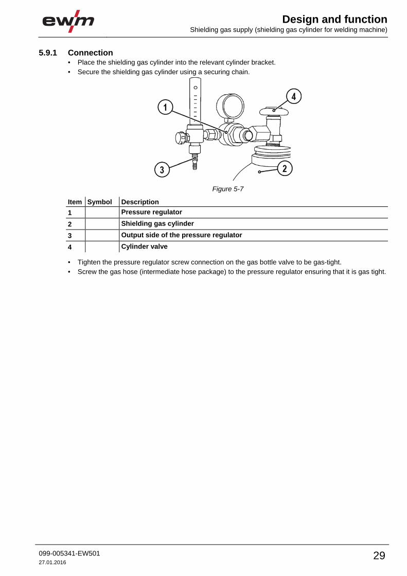
5.9.1 Connection • Place the shielding gas cylinder into the relevant cylinder bracket.
• Secure the shielding gas cylinder using a securing chain.
Figure 5-7
Item Symbol Description 0
1 Pressure regulator
2 Shielding gas cylinder
3 Output side of the pressure regulator
4 Cylinder valve
• Tighten the pressure regulator screw connection on the gas bottle valve to be gas-tight.
• Screw the gas hose (intermediate hose package) to the pressure regulator ensuring that it is gas tight.
Design and function Aligning the cable resistance
30 099-005341-EW501
27.01.2016
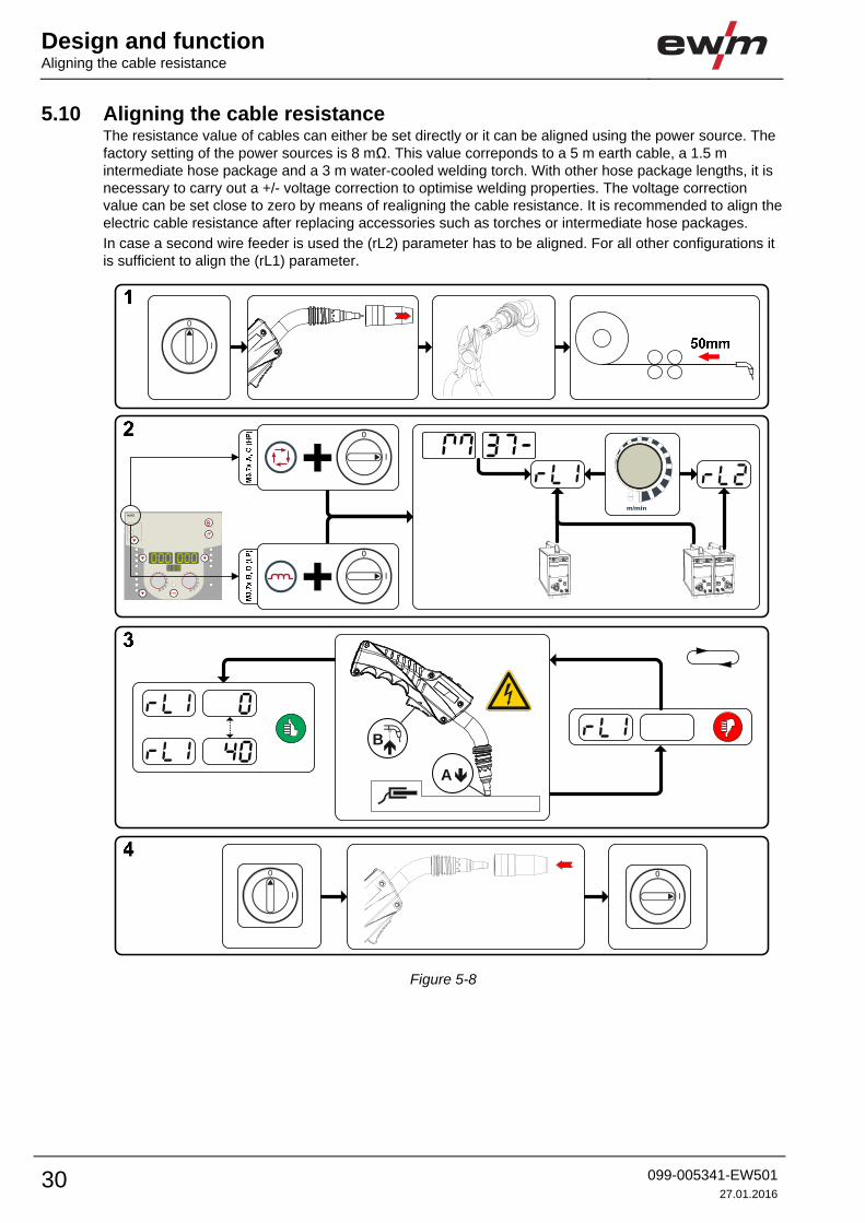
5.10 Aligning the cable resistance The resistance value of cables can either be set directly or it can be aligned using the power source. The
factory setting of the power sources is 8 mΩ. This value correponds to a 5 m earth cable, a 1.5 m
intermediate hose package and a 3 m water-cooled welding torch. With other hose package lengths, it is
necessary to carry out a +/- voltage correction to optimise welding properties. The voltage correction
value can be set close to zero by means of realigning the cable resistance. It is recommended to align the
electric cable resistance after replacing accessories such as torches or intermediate hose packages.
In case a second wire feeder is used the (rL2) parameter has to be aligned. For all other configurations it
is sufficient to align the (rL1) parameter.
l
0
l
0
m/min
B
A
Figure 5-8
Design and functionAligning the cable resistance
099-005341-EW501
27.01.2016 31
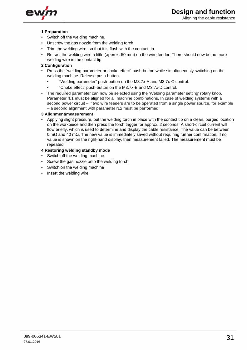
1 Preparation
• Switch off the welding machine.
• Unscrew the gas nozzle from the welding torch.
• Trim the welding wire, so that it is flush with the contact tip.
• Retract the welding wire a little (approx. 50 mm) on the wire feeder. There should now be no more
welding wire in the contact tip.
2 Configuration
• Press the "welding parameter or choke effect" push-button while simultaneously switching on the
welding machine. Release push-button.
• "Welding parameter" push-button on the M3.7x-A and M3.7x-C control.
• "Choke effect" push-button on the M3.7x-B and M3.7x-D control.
• The required parameter can now be selected using the 'Welding parameter setting' rotary knob.
Parameter rL1 must be aligned for all machine combinations. In case of welding systems with a
second power circuit – if two wire feeders are to be operated from a single power source, for example
– a second alignment with parameter rL2 must be performed.
3 Alignment/measurement
• Applying slight pressure, put the welding torch in place with the contact tip on a clean, purged location
on the workpiece and then press the torch trigger for approx. 2 seconds. A short-circuit current will
flow briefly, which is used to determine and display the cable resistance. The value can be between
0 mΩ and 40 mΩ. The new value is immediately saved without requiring further confirmation. If no
value is shown on the right-hand display, then measurement failed. The measurement must be
repeated.
4 Restoring welding standby mode
• Switch off the welding machine.
• Screw the gas nozzle onto the welding torch.
• Switch on the welding machine
• Insert the welding wire.
Design and function MIG/MAG welding
32 099-005341-EW501
27.01.2016
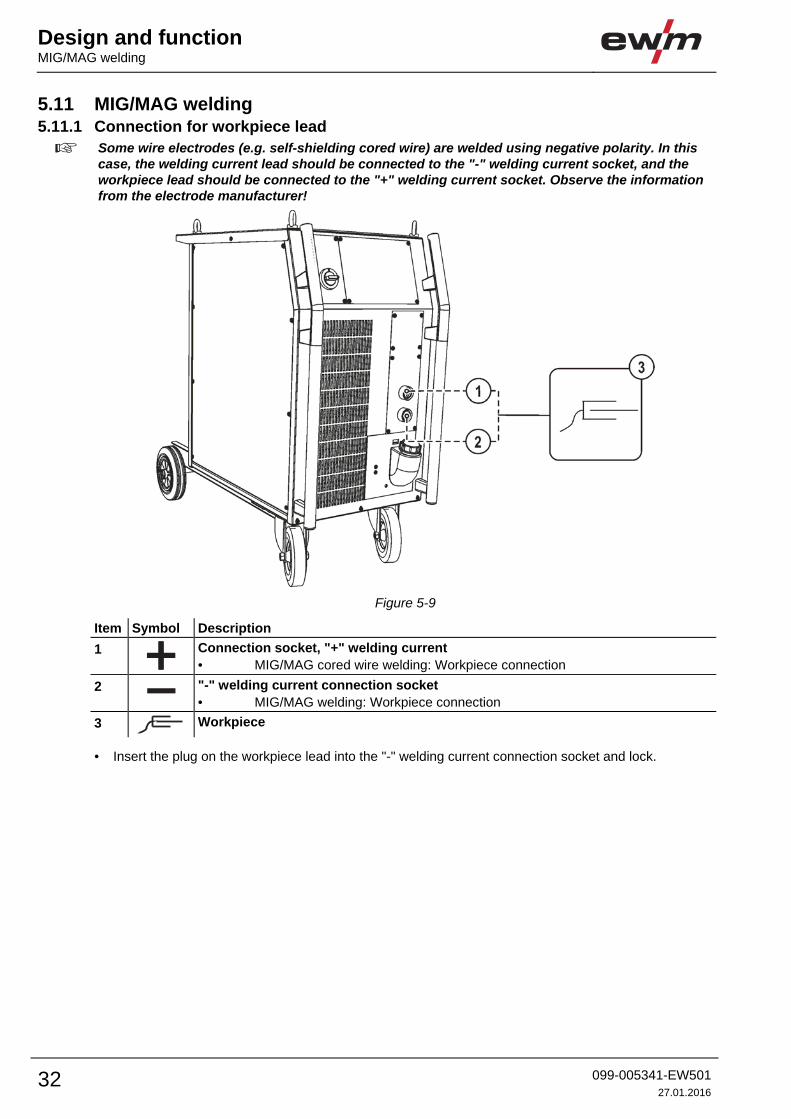
5.11 MIG/MAG welding 5.11.1 Connection for workpiece lead
Some wire electrodes (e.g. self-shielding cored wire) are welded using negative polarity. In this case, the welding current lead should be connected to the "-" welding current socket, and the workpiece lead should be connected to the "+" welding current socket. Observe the information from the electrode manufacturer!
Figure 5-9
Item Symbol Description 0
1
Connection socket, "+" welding current
• MIG/MAG cored wire welding: Workpiece connection
2 "-" welding current connection socket
• MIG/MAG welding: Workpiece connection
3
Workpiece
• Insert the plug on the workpiece lead into the "-" welding current connection socket and lock.
Design and functionTIG welding
099-005341-EW501
27.01.2016 33
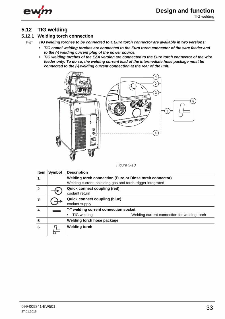
5.12 TIG welding 5.12.1 Welding torch connection
TIG welding torches to be connected to a Euro torch connector are available in two versions:
• TIG combi welding torches are connected to the Euro torch connector of the wire feeder and to the (-) welding current plug of the power source.
• TIG welding torches of the EZA version are connected to the Euro torch connector of the wire feeder only. To do so, the welding current lead of the intermediate hose package must be connected to the (-) welding current connection at the rear of the unit!
Figure 5-10
Item Symbol Description 0
1 Welding torch connection (Euro or Dinse torch connector)
Welding current, shielding gas and torch trigger integrated
2
Quick connect coupling (red)
coolant return
3
Quick connect coupling (blue)
coolant supply
4 "-" welding current connection socket
• TIG welding: Welding current connection for welding torch
5 Welding torch hose package
6
Welding torch

Design and function TIG welding
34 099-005341-EW501
27.01.2016
• Insert the central plug for the welding torch into the central connector and screw together with crown
nut.
• Insert the welding current plug of the combi welding torch into the (-) welding current connection
socket and lock into place by turning to the right (only in case of a separate welding current
connection).
If fitted:
• Lock connecting nipples of the cooling water tubes into the corresponding quick connect couplings:
Return line red to quick connect coupling, red (coolant return) and
supply line blue to quick connect coupling, blue (coolant supply).
5.12.2 Connection for workpiece lead
Figure 5-11
Item Symbol Description 0
1
Connection socket, "+" welding current
• TIG welding: Workpiece connection
2
Workpiece
• Insert the cable plug on the work piece lead into the "+" welding current connection socket and lock by
turning to the right.

Design and functionMMA welding
099-005341-EW501
27.01.2016 35
5.13 MMA welding
CAUTION
Risk of being crushed or burnt.
When replacing spent or new stick electrodes
• Switch off machine at the main switch
• Wear appropriate safety gloves
• Use insulated tongs to remove spent stick electrodes or to move welded workpieces and
• Always put the electrode holder down on an insulated surface.
5.13.1 Connecting the electrode holder and workpiece lead
Polarity depends on the instructions from the electrode manufacturer given on the electrode packaging.
Figure 5-12
Item Symbol Description 0
1
Connection socket, “+” welding current
2
Connection socket, “-” welding current
3
Workpiece
4
Electrode holder
• Insert cable plug of the electrode holder into either the "+" or "-" welding current connection socket and
lock by turning to the right.
• Insert cable plug of the workpiece lead into either the "+" or "-" welding current connection socket and
lock by turning to the right.
Design and function Remote control
36 099-005341-EW501
27.01.2016
5.13.2 Voltage reducing device (VRD) The voltage reduction device is only active on VRD machine versions.
To increase safety, particularly in hazardous environments (like shipbuilding, pipe construction or mining),
the machine is equipped with the VRD (Voltage-reducing device) voltage reduction device.
The VRD signal light is illuminated, when the voltage reduction device is operating without fault and the
output voltage is reduced to a value specified in the relevant standard (see technical data).
- See 8 Technical data chapter
- See 8 Technical data chapter
The voltage reducing device is a requirement in some countries and in many internal company safety
guidelines for power sources.
5.14 Remote control
CAUTION
Damage due to the use of non-genuine parts!
The manufacturer's warranty becomes void if non-genuine parts are used!
• Only use system components and options (power sources, welding torches, electrode
holders, remote controls, spare parts and replacement parts, etc.) from our range of
products!
• Only insert and lock accessory components into the relevant connection socket when the
machine is switched off.
The remote controls are operated on the 7-pole remote control connection socket (digital).
Please note the relevant documentation of the accessory components.
5.15 PC Interfaces
CAUTION
Equipment damage or faults may occur if the PC is connected incorrectly!
Not using the SECINT X10USB interface results in equipment damage or faults in signal
transmission. The PC may be destroyed due to high frequency ignition pulses.
• Interface SECINT X10USB must be connected between the PC and the welding machine!
• The connection must only be made using the cables supplied (do not use any additional
extension cables)!
PC 300 welding parameter software
Create all welding parameters quickly on the PC and easily transfer them to one or more welding
machines (accessories: set consisting of software, interface, connection leads).
Q-DOC 9000 welding data documentation software
(Accessories: set consisting of software, interface, connection leads)
The ideal tool for welding data documentation of, for example:
welding voltage and current, wire speed and motor current.
WELDQAS welding data monitoring and documentation system
Network-compatible welding data monitoring and documentation system for digital machines

Maintenance, care and disposalGeneral
099-005341-EW501
27.01.2016 37
6 Maintenance, care and disposal
DANGER
Improper maintenance and testing
The equipment may only be cleaned, repaired or tested by specialist, skilled persons! A
skilled person is one who, due to training, knowledge and experience, is able to
recognise the dangers that can occur during testing of this equipment as well as
possible subsequent damage and who is able to implement the required safety
procedures.
• Complete all tests given in the chapter below!
• Only put the equipment back into operation following a successful test.
Risk of injury from electric shock!
Cleaning machines that are not disconnected from the mains can lead to serious
injuries!
• Disconnect the machine completely from the mains.
• Remove the mains plug!
• Wait for 4 minutes until the capacitors have discharged!
Repair and maintenance work may only be performed by qualified authorised personnel; otherwise the
right to claim under warranty is void. In all service matters, always consult the dealer who supplied the
machine. Return deliveries of defective equipment subject to warranty may only be made through your
dealer. When replacing parts, use only original spare parts. When ordering spare parts, please quote the
machine type, serial number and item number of the machine, as well as the type designation and item
number of the spare part.
6.1 General When used in the specified environmental conditions and under normal operating conditions, this
machine is largely maintenance-free and requires a minimum of care.
There are some points, which should be observed, to guarantee fault-free operation of your welding
machine. Among these are regular cleaning and checking as described below, depending on the pollution
level of the environment and the length of time the unit is in use.
6.2 Maintenance work, intervals 6.2.1 Daily maintenance tasks
• Check that all connections and wearing parts are hand-tight and tighten if necessary.
• Check that all screw and plug connections and replaceable parts are secured correctly, tighten if
necessary.
• Remove any spatter.
• Clean the wire feed rollers on a regular basis (depending on the degree of soiling).
6.2.1.1 Visual inspection
• Check hose package and power connections for exterior damage and replace or have repaired by
specialist staff as necessary!
• Mains supply lead and its strain relief
• Gas tubes and their switching equipment (solenoid valve)
• Other, general condition
6.2.1.2 Functional test
• Check correct mounting of the wire spool.
• Welding current cables (check that they are fitted correctly and secured)
• Gas cylinder securing elements
• Operating, message, safety and adjustment devices (Functional test)

Maintenance, care and disposal Disposing of equipment
38 099-005341-EW501
27.01.2016
6.2.2 Monthly maintenance tasks
6.2.2.1 Visual inspection
• Casing damage (front, rear and side walls)
• Wheels and their securing elements
• Transport elements (strap, lifting lugs, handle)
• Check coolant tubes and their connections for impurities
6.2.2.2 Functional test
• Selector switches, command devices, emergency stop devices, voltage reducing devices, message
and control lamps
• Check that the wire guide elements (inlet nipple, wire guide tube) are fitted securely.
6.2.3 Annual test (inspection and testing during operation)
The welding machine may only be tested by competent, capable personsl. A capable person is one who, because of his training, knowledge and experience, is able to recognise the dangers that can occur while testing welding power sources as well as possible subsequent damage and who is able to implement the required safety procedures.
For more information refer to the "Warranty registration" brochure supplied and our information regarding warranty, maintenance and testing at www.ewm-group.com!
A periodic test according to IEC 60974-4 "Periodic inspection and test" has to be carried out. In addition
to the regulations on testing given here, the relevant local laws and regulations must also be observed.
6.3 Disposing of equipment
Proper disposal! The machine contains valuable raw materials, which should be recycled, and electronic components, which must be disposed of.
• Do not dispose of in household waste! • Observe the local regulations regarding disposal!
6.3.1 Manufacturer's declaration to the end user • According to European provisions (guideline 2002/96/EG of the European Parliament and the Council
of January, 27th 2003), used electric and electronic equipment may no longer be placed in unsorted
municipal waste. It must be collected separately. The symbol depicting a waste container on wheels
indicates that the equipment must be collected separately.
This machine is to be placed for disposal or recycling in the waste separation systems provided for
this purpose.
• According to German law (law governing the distribution, taking back and environmentally correct
disposal of electric and electronic equipment (ElektroG) from 16.03.2005), used machines are to be
placed in a collection system separate from unsorted municipal waste. The public waste management
utilities (communities) have created collection points at which used equipment from private
households can be disposed of free of charge.
• Information about giving back used equipment or about collections can be obtained from the
respective municipal administration office.
• EWM participates in an approved waste disposal and recycling system and is registered in the Used
Electrical Equipment Register (EAR) under number WEEE DE 57686922.
• In addition to this, returns are also possible throughout Europe via EWM sales partners.
6.4 Meeting the requirements of RoHS We, EWM AG Mündersbach, hereby confirm that all products supplied by us which are affected by the
RoHS Directive, meet the requirements of the RoHS (Directive 2011/65/EU).
Rectifying faultsChecklist for rectifying faults
099-005341-EW501
27.01.2016 39
7 Rectifying faults All products are subject to rigorous production checks and final checks. If, despite this, something fails to
work at any time, please check the product using the following flowchart. If none of the fault rectification
procedures described leads to the correct functioning of the product, please inform your authorised
dealer.
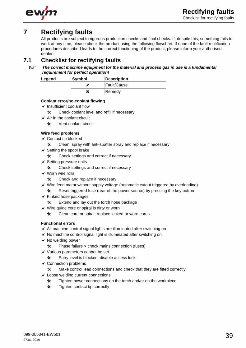
7.1 Checklist for rectifying faults
The correct machine equipment for the material and process gas in use is a fundamental requirement for perfect operation!
Legend Symbol Description
Fault/Cause
Remedy
Coolant error/no coolant flowing
Insufficient coolant flow
Check coolant level and refill if necessary
Air in the coolant circuit
Vent coolant circuit
Wire feed problems
Contact tip blocked
Clean, spray with anti-spatter spray and replace if necessary
Setting the spool brake
Check settings and correct if necessary
Setting pressure units
Check settings and correct if necessary
Worn wire rolls
Check and replace if necessary
Wire feed motor without supply voltage (automatic cutout triggered by overloading)
Reset triggered fuse (rear of the power source) by pressing the key button
Kinked hose packages
Extend and lay out the torch hose package
Wire guide core or spiral is dirty or worn
Clean core or spiral; replace kinked or worn cores
Functional errors
All machine control signal lights are illuminated after switching on
No machine control signal light is illuminated after switching on
No welding power
Phase failure > check mains connection (fuses)
Various parameters cannot be set
Entry level is blocked, disable access lock
Connection problems
Make control lead connections and check that they are fitted correctly.
Loose welding current connections
Tighten power connections on the torch and/or on the workpiece
Tighten contact tip correctly

Rectifying faults Error messages
40 099-005341-EW501
27.01.2016
7.2 Error messages
A welding machine error is indicated by an error code being displayed (see table) on the display on the machine control. In the event of a machine error, the power unit is shut down.
The display of possible error numbers depends on the machine version (interfaces/functions).
• Document machine errors and inform service staff as necessary.
• If multiple errors occur, these are displayed in succession.
Error Category Possible cause Remedy
a) b) c)
Error 1
(Ov.Vol)
- - x Mains overvoltage Check the mains voltages and compare with
the connection voltages of the welding
machine Error 2
(Un.Vol)
- - x Mains undervoltage
Error 3
(Temp)
x - - Welding machine excess
temperature
Allow the machine to cool down (mains
switch to "1")
Error 4
(Water)
x x - Low coolant level Top off the coolant
Leak in the coolant circuit >
rectify the leak and top off the coolant
Coolant pump is not working > check excess
current trigger on air cooling unit
Error 5
(Wi.Spe)
x - - Wire feeder/speedometer
error
Check the wire feeder
speedometer is not issuing a signal,
M3.51 defective > inform Service
Error 6
(gas)
x - - Shielding gas error Check shielding gas supply (for machines
with shielding gas monitoring)
Error 7
(Se.Vol)
- - x Secondary excess voltage Inverter error > inform Service
Error 8
(no PE)
- - x Earth fault between welding
wire and earth line
Separate the connection between the
welding wire and casing or an earthed object
Error 9
(fast stop)
x - - Fast cut-out
triggered by BUSINT X11 or
RINT X12
Rectify error on robot
Error 10
(no arc)
- x - Arc break
triggered by BUSINT X11 or
RINT X12
Check wire feeding
Error 11
(no ign)
- x - Ignition fault after 5 s
triggered by BUSINT X11 or
RINT X12
Check wire feeding
Error 14
(no DV)
- x - Wire feeder not detected.
Control cable not connected.
Check cable connection
Incorrect ID numbers
assigned during operation
with multiple wire feeders.
Check assignment of ID numbers
Error 15
(DV2?)
- x - Wire feeder 2 not detected.
Control cable not connected.
Check cable connection
Error 16
(VRD)
- - x VRD (open circuit voltage
reduction error)
Inform Service
Error 17
(WF. Ov.)
- x x Wire feed mechanism
overcurrent detection
Check the wire feeding
Error 18
(WF. Sl.)
- x x No speedometer signal from
second wire feeder (slave
drive)
Check the connection and particularly the
speedometer of the second wire feeder
(slave drive).
Rectifying faultsError messages
099-005341-EW501
27.01.2016 41
Error Category Possible cause Remedy
a) b) c)
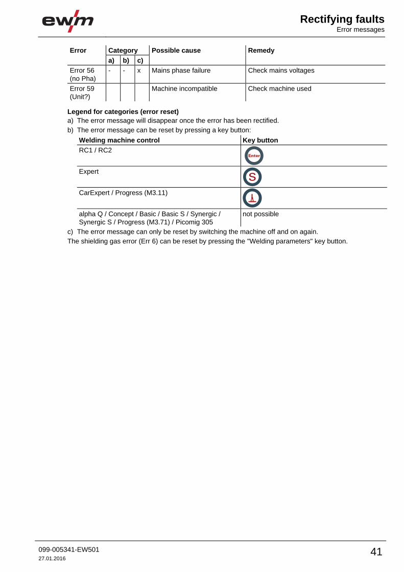
Error 56
(no Pha)
- - x Mains phase failure Check mains voltages
Error 59
(Unit?)
Machine incompatible Check machine used
Legend for categories (error reset)
a) The error message will disappear once the error has been rectified.
b) The error message can be reset by pressing a key button:
Welding machine control Key button
RC1 / RC2
Expert
CarExpert / Progress (M3.11)
alpha Q / Concept / Basic / Basic S / Synergic /
Synergic S / Progress (M3.71) / Picomig 305
not possible
c) The error message can only be reset by switching the machine off and on again.
The shielding gas error (Err 6) can be reset by pressing the "Welding parameters" key button.
Rectifying faults Resetting JOBs (welding tasks) to the factory settings
42 099-005341-EW501
27.01.2016
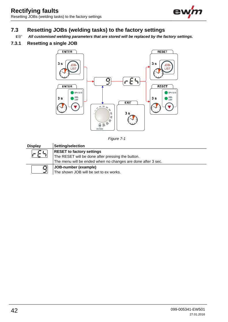
7.3 Resetting JOBs (welding tasks) to the factory settings
All customised welding parameters that are stored will be replaced by the factory settings.
7.3.1 Resetting a single JOB
JOB-LIST
JOB-LIST
Figure 7-1
Display Setting/selection
RESET to factory settings
The RESET will be done after pressing the button.
The menu will be ended when no changes are done after 3 sec.
JOB-number (example)
The shown JOB will be set to ex works.
Rectifying faultsResetting JOBs (welding tasks) to the factory settings
099-005341-EW501
27.01.2016 43
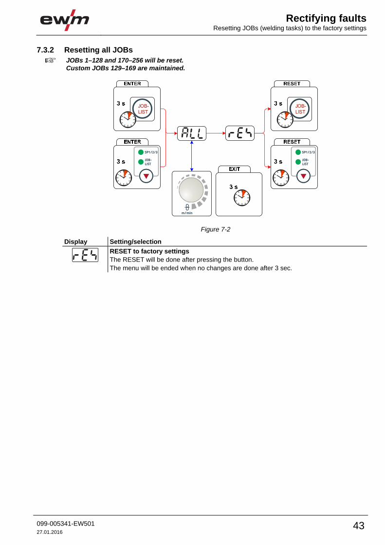
7.3.2 Resetting all JOBs
JOBs 1–128 and 170–256 will be reset. Custom JOBs 129–169 are maintained.
JOB-LIST
JOB-LIST
Figure 7-2
Display Setting/selection
RESET to factory settings
The RESET will be done after pressing the button.
The menu will be ended when no changes are done after 3 sec.
Rectifying faults Vent coolant circuit
44 099-005341-EW501
27.01.2016
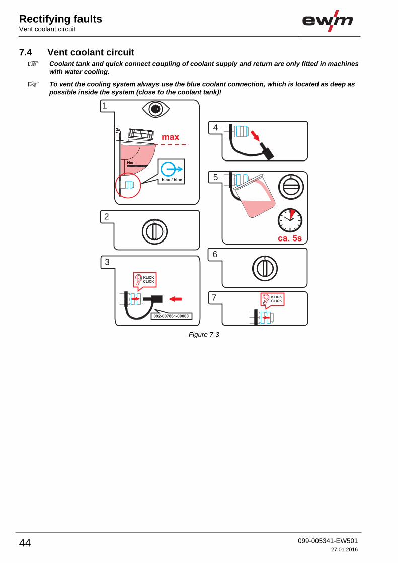
7.4 Vent coolant circuit
Coolant tank and quick connect coupling of coolant supply and return are only fitted in machines with water cooling.
To vent the cooling system always use the blue coolant connection, which is located as deep as possible inside the system (close to the coolant tank)!
max
1
2
ca. 5s
3
4
7
6
5
KLICK
CLICK
KLICK
CLICK
092-007861-00000
blau / blue
l
0
l
0
l
0
Figure 7-3
Technical dataTaurus 351 Synergic S MM FDG
099-005341-EW501
27.01.2016 45
8 Technical data Performance specifications and guarantee only in connection with original spare and
replacement parts!
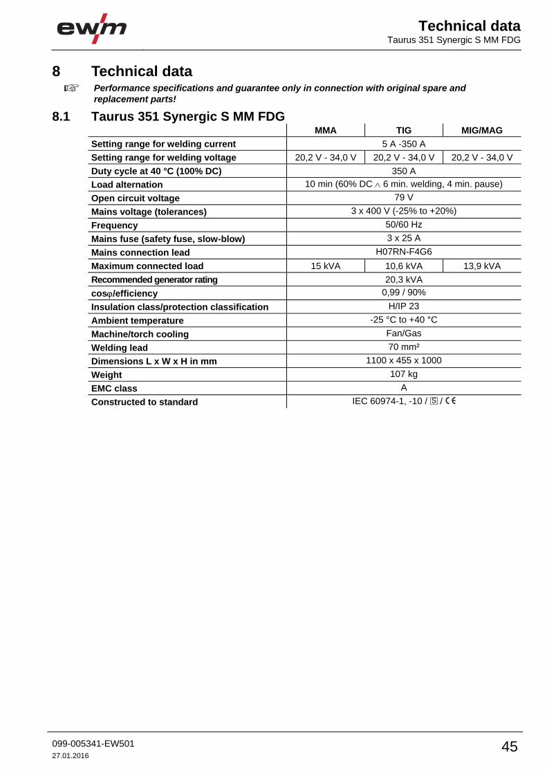
8.1 Taurus 351 Synergic S MM FDG MMA TIG MIG/MAG
Setting range for welding current 5 A -350 A
Setting range for welding voltage 20,2 V - 34,0 V 20,2 V - 34,0 V 20,2 V - 34,0 V
Duty cycle at 40 °C (100% DC) 350 A
Load alternation 10 min (60% DC 6 min. welding, 4 min. pause)
Open circuit voltage 79 V
Mains voltage (tolerances) 3 x 400 V (-25% to +20%)
Frequency 50/60 Hz
Mains fuse (safety fuse, slow-blow) 3 x 25 A
Mains connection lead H07RN-F4G6
Maximum connected load 15 kVA 10,6 kVA 13,9 kVA
Recommended generator rating 20,3 kVA
cos/efficiency 0,99 / 90%
Insulation class/protection classification H/IP 23
Ambient temperature -25 °C to +40 °C
Machine/torch cooling Fan/Gas
Welding lead 70 mm²
Dimensions L x W x H in mm 1100 x 455 x 1000
Weight 107 kg
EMC class A
Constructed to standard IEC 60974-1, -10 / /
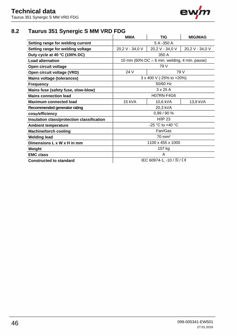
Technical data Taurus 351 Synergic S MM VRD FDG
46 099-005341-EW501
27.01.2016
8.2 Taurus 351 Synergic S MM VRD FDG MMA TIG MIG/MAG
Setting range for welding current 5 A -350 A
Setting range for welding voltage 20,2 V - 34,0 V 20,2 V - 34,0 V 20,2 V - 34,0 V
Duty cycle at 40 °C (100% DC) 350 A
Load alternation 10 min (60% DC 6 min. welding, 4 min. pause)
Open circuit voltage 79 V
Open circuit voltage (VRD) 24 V 79 V
Mains voltage (tolerances) 3 x 400 V (-25% to +20%)
Frequency 50/60 Hz
Mains fuse (safety fuse, slow-blow) 3 x 25 A
Mains connection lead H07RN-F4G6
Maximum connected load 15 kVA 10,6 kVA 13,9 kVA
Recommended generator rating 20,3 kVA
cos/efficiency 0,99 / 90 %
Insulation class/protection classification H/IP 23
Ambient temperature -25 °C to +40 °C
Machine/torch cooling Fan/Gas
Welding lead 70 mm²
Dimensions L x W x H in mm 1100 x 455 x 1000
Weight 107 kg
EMC class A
Constructed to standard IEC 60974-1, -10 / /
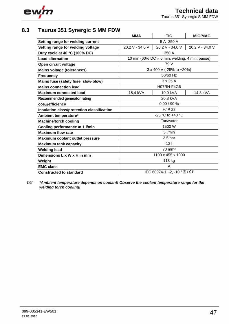
Technical dataTaurus 351 Synergic S MM FDW
099-005341-EW501
27.01.2016 47
8.3 Taurus 351 Synergic S MM FDW MMA TIG MIG/MAG
Setting range for welding current 5 A -350 A
Setting range for welding voltage 20,2 V - 34,0 V 20,2 V - 34,0 V 20,2 V - 34,0 V
Duty cycle at 40 °C (100% DC) 350 A
Load alternation 10 min (60% DC 6 min. welding, 4 min. pause)
Open circuit voltage 79 V
Mains voltage (tolerances) 3 x 400 V (-25% to +20%)
Frequency 50/60 Hz
Mains fuse (safety fuse, slow-blow) 3 x 25 A
Mains connection lead H07RN-F4G6
Maximum connected load 15,4 kVA 10,9 kVA 14,3 kVA
Recommended generator rating 20,8 kVA
cos/efficiency 0,99 / 90 %
Insulation class/protection classification H/IP 23
Ambient temperature* -25 °C to +40 °C
Machine/torch cooling Fan/water
Cooling performance at 1 l/min 1500 W
Maximum flow rate 5 l/min
Maximum coolant outlet pressure 3.5 bar
Maximum tank capacity 12 l
Welding lead 70 mm²
Dimensions L x W x H in mm 1100 x 455 x 1000
Weight 118 kg
EMC class A
Constructed to standard IEC 60974-1, -2, -10 / /
*Ambient temperature depends on coolant! Observe the coolant temperature range for the welding torch cooling!
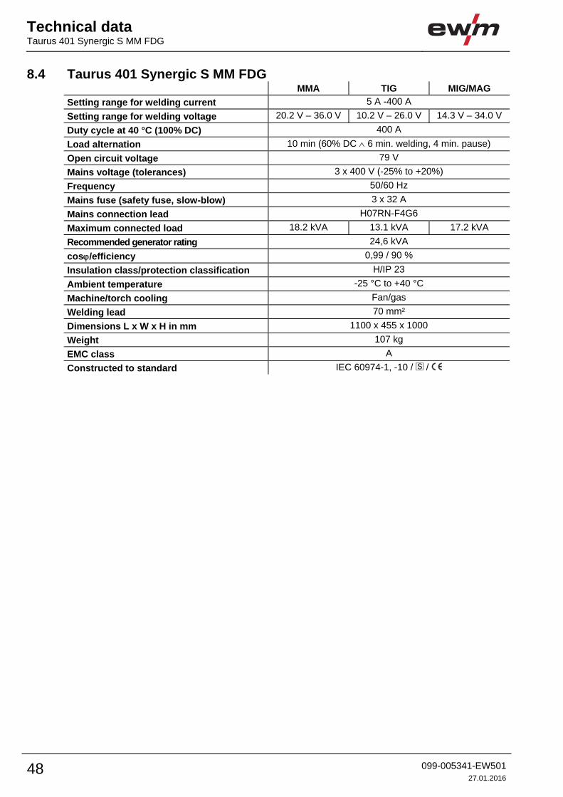
Technical data Taurus 401 Synergic S MM FDG
48 099-005341-EW501
27.01.2016
8.4 Taurus 401 Synergic S MM FDG MMA TIG MIG/MAG
Setting range for welding current 5 A -400 A
Setting range for welding voltage 20.2 V – 36.0 V 10.2 V – 26.0 V 14.3 V – 34.0 V
Duty cycle at 40 °C (100% DC) 400 A
Load alternation 10 min (60% DC 6 min. welding, 4 min. pause)
Open circuit voltage 79 V
Mains voltage (tolerances) 3 x 400 V (-25% to +20%)
Frequency 50/60 Hz
Mains fuse (safety fuse, slow-blow) 3 x 32 A
Mains connection lead H07RN-F4G6
Maximum connected load 18.2 kVA 13.1 kVA 17.2 kVA
Recommended generator rating 24,6 kVA
cos/efficiency 0,99 / 90 %
Insulation class/protection classification H/IP 23
Ambient temperature -25 °C to +40 °C
Machine/torch cooling Fan/gas
Welding lead 70 mm²
Dimensions L x W x H in mm 1100 x 455 x 1000
Weight 107 kg
EMC class A
Constructed to standard IEC 60974-1, -10 / /

Technical dataTaurus 401 Synergic S MM FDW
099-005341-EW501
27.01.2016 49
8.5 Taurus 401 Synergic S MM FDW MMA TIG MIG/MAG
Setting range for welding current 5 A -400 A
Setting range for welding voltage 20.2 V – 36.0 V 10.2 V – 26.0 V 14.3 V – 34.0 V
Duty cycle at 40 °C (100% DC) 400 A
Load alternation 10 min (60% DC 6 min. welding, 4 min. pause)
Open circuit voltage 79 V
Mains voltage (tolerances) 3 x 400 V (-25% to +20%)
Frequency 50/60 Hz
Mains fuse (safety fuse, slow-blow) 3 x 32 A
Mains connection lead H07RN-F4G6
Maximum connected load 18,5 kVA 13,5 kVA 17,5 kVA
Recommended generator rating 25,0 kVA
cos/efficiency 0,99 / 90 %
Insulation class/protection classification H/IP 23
Ambient temperature* -25 °C to +40 °C
Machine/torch cooling Fan/water
Cooling performance at 1 l/min 1500 W
Maximum flow rate 5 l/min
Maximum coolant outlet pressure 3.5 bar
Maximum tank capacity 12 l
Welding lead 70 mm²
Dimensions L x W x H in mm 1100 x 455 x 1000
Weight 118 kg
EMC class A
Constructed to standard IEC 60974-1, -2, -10 / /
*Ambient temperature depends on coolant! Observe the coolant temperature range for the welding torch cooling!

Technical data Taurus 451 Synergic S MM FDG
50 099-005341-EW501
27.01.2016
8.6 Taurus 451 Synergic S MM FDG MMA TIG MIG/MAG
Setting range welding current 5 to 450 A
Setting range welding voltage 20,2 to 38 V 10,2 to 28,0 V 14,3 to 36,5 V
Duty cycle at 40 °C (80 % DC) 450 A
Duty cycle at 40 °C (100 % DC) 420 A
Load alternation 10 min. (60% DC 6 min. welding, 4 min. break)
Open circuit voltage 79 V
Mains voltage (tolerances) 3 x 400 V (-25% to +20%)
Frequency 50/60 Hz
Mains fuse (safety fuse, slow-blow) 3 x 25 A
Mains connection lead H07RN-F4G6
Maximum connected load 21,6 kVA 15,9 kVA 20,7 kVA
Recommended generator rating 29,2 kVA
Cos/efficiency 0.99 / 90 %
Insulation class/protection classification H/IP 23
Ambient temperature -25 °C to +40 °C
Machine/torch cooling Fan / gas
Workpiece lead 70 mm2
Dimensions L x W x H in mm 1100 x 455 x 1000
Weight 118 kg
EMC class A
Constructed to standards IEC 60974-1, -10 / /

Technical dataTaurus 451 Synergic S MM FDW
099-005341-EW501
27.01.2016 51
8.7 Taurus 451 Synergic S MM FDW MMA TIG MIG/MAG
Setting range welding current 5 to 450 A
Setting range welding voltage 20,2 to 38 V 10,2 to 28,0 V 14,3 to 36,5 V
Duty cycle at 40 °C (80 % DC) 450 A
Duty cycle at 40 °C (100 % DC) 420 A
Load alternation 10 min. (60% DC 6 min. welding, 4 min. break)
Open circuit voltage 79 V
Mains voltage (tolerances) 3 x 400 V (-25% to +20%)
Frequency 50/60 Hz
Mains fuse (safety fuse, slow-blow) 3 x 25 A
Mains connection lead H07RN-F4G6
Maximum connected load 22,2 kVA 16,3 kVA 21,1 kVA
Recommended generator rating 29,7 kVA
Cos/efficiency 0.99 / 90 %
Insulation class/protection classification H/IP 23
Ambient temperature -25 C to +40 C
Machine/torch cooling Fan / water
Cooling capacity at 1 l/min 1500 W
Maximum flow rate 5 l/min.
Maximum coolant output pressure 3.5 bar
Maximum tank capacity 12 l
Workpiece lead 70 mm2
Dimensions L x W x H in mm 1100 x 455 x 1000
Weight 129 kg
EMC class A
Constructed to standards IEC 60974-1, -2, -10 / /
*Ambient temperature depends on coolant! Observe the coolant temperature range for the welding torch cooling!
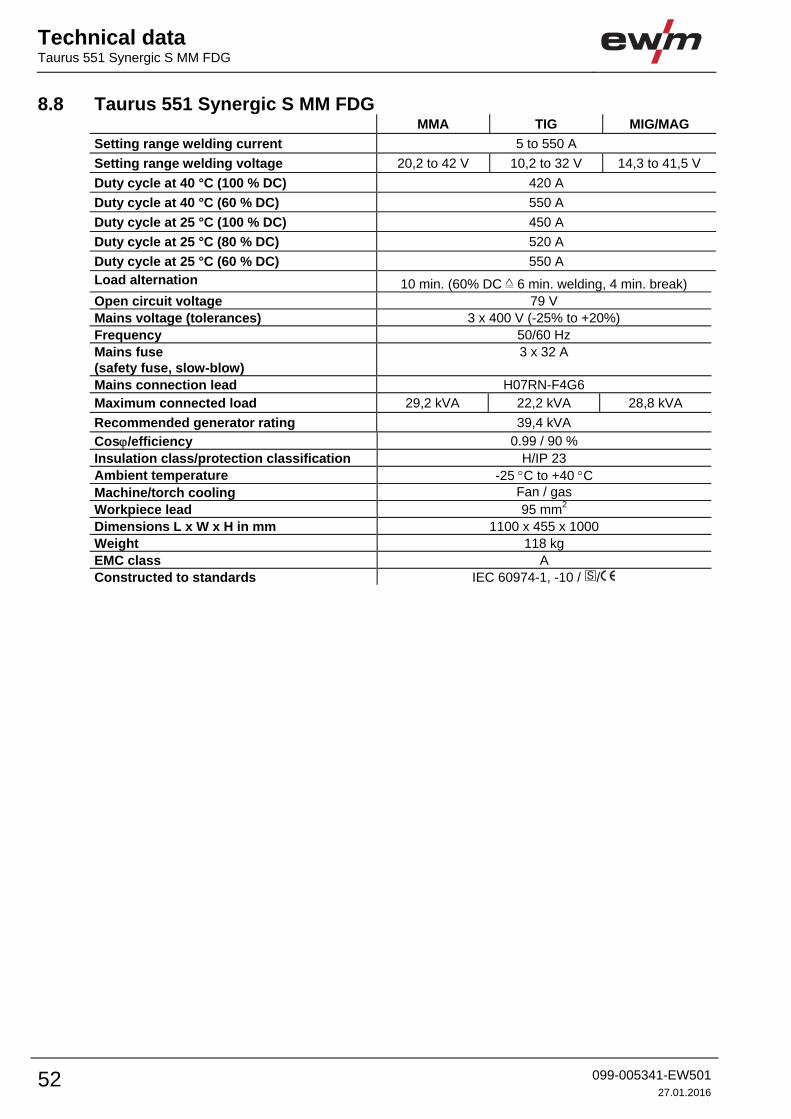
Technical data Taurus 551 Synergic S MM FDG
52 099-005341-EW501
27.01.2016
8.8 Taurus 551 Synergic S MM FDG MMA TIG MIG/MAG
Setting range welding current 5 to 550 A
Setting range welding voltage 20,2 to 42 V 10,2 to 32 V 14,3 to 41,5 V
Duty cycle at 40 °C (100 % DC) 420 A
Duty cycle at 40 °C (60 % DC) 550 A
Duty cycle at 25 °C (100 % DC) 450 A
Duty cycle at 25 °C (80 % DC) 520 A
Duty cycle at 25 °C (60 % DC) 550 A
Load alternation 10 min. (60% DC 6 min. welding, 4 min. break)
Open circuit voltage 79 V
Mains voltage (tolerances) 3 x 400 V (-25% to +20%)
Frequency 50/60 Hz
Mains fuse
(safety fuse, slow-blow)
3 x 32 A
Mains connection lead H07RN-F4G6
Maximum connected load 29,2 kVA 22,2 kVA 28,8 kVA
Recommended generator rating 39,4 kVA
Cos/efficiency 0.99 / 90 %
Insulation class/protection classification H/IP 23
Ambient temperature -25 C to +40 C
Machine/torch cooling Fan / gas
Workpiece lead 95 mm2
Dimensions L x W x H in mm 1100 x 455 x 1000
Weight 118 kg
EMC class A
Constructed to standards IEC 60974-1, -10 / /
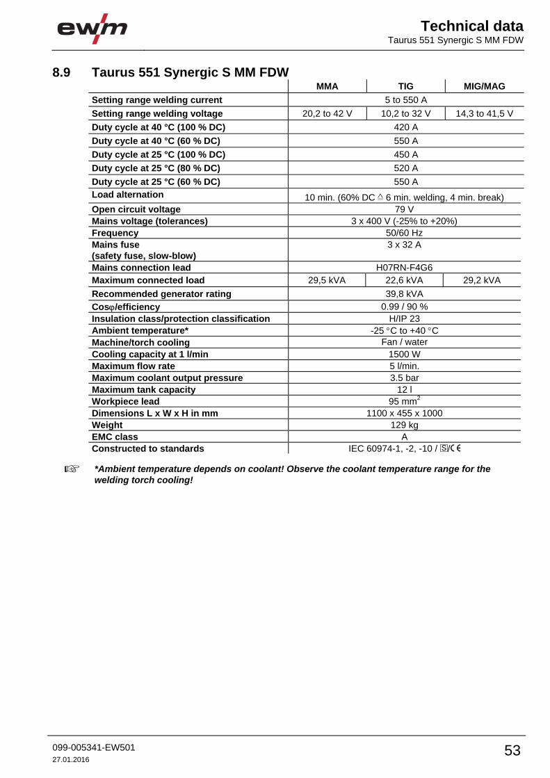
Technical dataTaurus 551 Synergic S MM FDW
099-005341-EW501
27.01.2016 53
8.9 Taurus 551 Synergic S MM FDW MMA TIG MIG/MAG
Setting range welding current 5 to 550 A
Setting range welding voltage 20,2 to 42 V 10,2 to 32 V 14,3 to 41,5 V
Duty cycle at 40 °C (100 % DC) 420 A
Duty cycle at 40 °C (60 % DC) 550 A
Duty cycle at 25 °C (100 % DC) 450 A
Duty cycle at 25 °C (80 % DC) 520 A
Duty cycle at 25 °C (60 % DC) 550 A
Load alternation 10 min. (60% DC 6 min. welding, 4 min. break)
Open circuit voltage 79 V
Mains voltage (tolerances) 3 x 400 V (-25% to +20%)
Frequency 50/60 Hz
Mains fuse
(safety fuse, slow-blow)
3 x 32 A
Mains connection lead H07RN-F4G6
Maximum connected load 29,5 kVA 22,6 kVA 29,2 kVA
Recommended generator rating 39,8 kVA
Cos/efficiency 0.99 / 90 %
Insulation class/protection classification H/IP 23
Ambient temperature* -25 C to +40 C
Machine/torch cooling Fan / water
Cooling capacity at 1 l/min 1500 W
Maximum flow rate 5 l/min.
Maximum coolant output pressure 3.5 bar
Maximum tank capacity 12 l
Workpiece lead 95 mm2
Dimensions L x W x H in mm 1100 x 455 x 1000
Weight 129 kg
EMC class A
Constructed to standards IEC 60974-1, -2, -10 / /
*Ambient temperature depends on coolant! Observe the coolant temperature range for the welding torch cooling!

Accessories System components
54 099-005341-EW501
27.01.2016
9 Accessories Performance-dependent accessories like torches, workpiece leads, electrode holders or
intermediate hose packages are available from your authorised dealer.
9.1 System components Type Designation Item no.
drive 4X HP Wire feeder, water-cooled, Euro torch connector 090-005392-00502
drive 4X HP MMA Wire feeder, water-cooled, Euro torch connector
with connection capability for electrode holder or
gouging torch
090-005392-51502
drive 4X LP Wire feeder, water-cooled, Euro torch connector 090-005412-00502
drive 4X LP MMA Wire feeder, water-cooled, Euro torch connector 090-005412-51502
drive 4X IC HP Wire feeder, water-cooled, Euro torch connector 090-005414-00502
drive 4X IC LP Wire feeder, water-cooled, Euro torch connector 090-005415-00502
9.2 General accessories Type Designation Item no.
AK300 Wire spool adapter K300 094-001803-00001
TYP 1 Frost protection tester 094-014499-00000
KF 23E-10 Coolant (-10 °C), 9.3 l 094-000530-00000
KF 23E-200 Coolant (-10 °C), 200 litres 094-000530-00001
KF 37E-10 Coolant (-20 °C), 9.3 l 094-006256-00000
KF 37E-200 Coolant (-20 °C), 200 l 094-006256-00001
DMDIN TN 200B AR/MIX 35L Manometer pressure regulator 094-000009-00000
GH 2X1/4'' 2M Gas hose 094-000010-00001
5POLE/CEE/32A/M Machine plug 094-000207-00000
HOSE BRIDGE UNI Tube bridge 092-007843-00000
9.3 Remote control/connecting and extension cable 9.3.1 7-pole connection
Type Designation Item no.
R40 7POL Remote control, 10 programs 090-008088-00000
R50 7POL Remote control, all welding machine functions can
be set directly at the workplace
090-008776-00000
FRV 7POL 0.5 m Extension/connecting cable 092-000201-00004
FRV 7POL 5 m Extension/connecting cable 092-000201-00003
FRV 7POL 10 m Extension/connecting cable 092-000201-00000
FRV 7POL 20 m Extension/connecting cable 092-000201-00001
FRV 7POL 25M Extension/connecting cable 092-000201-00007

AccessoriesOptions
099-005341-EW501
27.01.2016 55
9.4 Options Type Designation Item no.
ON LB Wheels 160x40MM Retrofit option for locking brake for machine wheels 092-002110-00000
ON Hose/FR Mount DK 4L Mounting for hoses and remote controls for
machines with 4L pivot support (092-002112-00000
and 092-002113-00000)
092-002117-00000
ON Hose/FR Mount Optional holder for tubes and remote control for
machines without pivot support
092-002116-00000
ON Filter T/P Retrofit option contamination filter for air inlet 092-002092-00000
ON Tool Box Retrofit option tool box 092-002138-00000
ON Holder Gas Bottle <50L Holding plate for gas cylinders smaller than 50 litres 092-002151-00000
ON Shock Protect Ram protection retrofit option 092-002154-00000

Appendix A Overview of EWM branches
56 099-005341-EW501
27.01.2016
10 Appendix A 10.1 Overview of EWM branches
EWM AG Türkiye İrtibat Bürosu
İkitelli OSB Mah. · Marmara Sanayi Sitesi P Blok Apt. No: 44
Küçükçekmece / İstanbul Türkiye
Tel.: +90 212 494 32 19
www.ewm-istanbul.com.tr · [email protected]
Plants Branches More than 400 EWM sales partners worldwide
HeadquartersEWM AG
Dr. Günter-Henle-Straße 8
56271 Mündersbach · Germany
Tel: +49 2680 181-0 · Fax: -244
www.ewm-group.com · [email protected]
Technology centreEWM AG
Forststraße 7-13
56271 Mündersbach · Germany
Tel: +49 2680 181-0 · Fax: -144
www.ewm-group.com · [email protected]
EWM AG
Dr. Günter-Henle-Straße 8
56271 Mündersbach · Germany
Tel: +49 2680 181-0 · Fax: -244
www.ewm-group.com · [email protected]
EWM HIGH TECHNOLOGY (Kunshan) Ltd.
10 Yuanshan Road, Kunshan · New & Hi-tech Industry Development Zone
Kunshan City · Jiangsu · Post code 215300 · People´s Republic of China
Tel: +86 512 57867-188 · Fax: -182
www.ewm.cn · [email protected] · [email protected]
EWM HIGHTEC WELDING s.r.o.
9. května 718 / 31
407 53 Jiříkov · Czech Republic
Tel.: +420 412 358-551 · Fax: -504
www.ewm-jirikov.cz · [email protected]
Production, Sales and Service
Sales and Service Germany
Sales and Service InternationalEWM HIGH TECHNOLOGY (Kunshan) Ltd.
10 Yuanshan Road, Kunshan · New & Hi-tech Industry Development Zone
Kunshan City · Jiangsu · Post code 215300 · People´s Republic of China
Tel: +86 512 57867-188 · Fax: -182
www.ewm.cn · [email protected] · [email protected]
EWM HIGHTEC WELDING GmbH
Wiesenstraße 27b
4812 Pinsdorf · Austria · Tel: +43 7612 778 02-0 · Fax: -20
www.ewm-austria.at · [email protected]
EWM HIGHTEC WELDING UK Ltd.
Unit 2B Coopies Way · Coopies Lane Industrial Estate
Morpeth · Northumberland · NE61 6JN · Great Britain
Tel: +44 1670 505875 · Fax: -514305
www.ewm-morpeth.co.uk · [email protected]
EWM HIGHTEC WELDING Sales s.r.o. / Prodejní a poradenské centrum
Tyršova 2106
256 01 Benešov u Prahy · Czech Republic
Tel: +420 317 729-517 · Fax: -712
www.ewm-benesov.cz · [email protected]
EWM AG
Sales and Technology Centre
Grünauer Fenn 4
14712 Rathenow · Tel: +49 3385 49402-0 · Fax: -20
www.ewm-rathenow.de · [email protected]
EWM AG
Rudolf-Winkel-Straße 7-9
37079 Göttingen · Tel: +49 551-3070713-0 · Fax: -20
www.ewm-goettingen.de · [email protected]
EWM AG
Sachsstraße 28
50259 Pulheim · Tel: +49 2234 697-047 · Fax: -048
www.ewm-pulheim.de · [email protected]
EWM AG
August-Horch-Straße 13a
56070 Koblenz · Tel: +49 261 963754-0 · Fax: -10
www.ewm-koblenz.de · [email protected]
EWM AG
Eiserfelder Straße 300
57080 Siegen · Tel: +49 271 3878103-0 · Fax: -9
www.ewm-siegen.de · [email protected]
EWM HIGHTEC WELDING GmbH
Sales and Technology Centre
Draisstraße 2a
69469 Weinheim · Tel: +49 6201 84557-0 · Fax: -20
www.ewm-weinheim.de · [email protected]
EWM Schweißtechnik Handels GmbH
Karlsdorfer Straße 43
88069 Tettnang · Tel: +49 7542 97998-0 · Fax: -29
www.ewm-tettnang.de · [email protected]
EWM Schweißtechnik Handels GmbH
Heinkelstraße 8
89231 Neu-Ulm · Tel: +49 731 7047939-0 · Fax: -15
www.ewm-neu-ulm.de · [email protected]
Liaison office
Liaison office Turkey