Embed Size (px)
Citation preview
1
Weld Toe Stress Concentrations in Multi Planar
Stiffened Tubular KK Joints
C. O. Woghiren1, a and F. P. Brennan2,b
1Mobil Producing Nigeria Unlimited, Room 6B 28A, Mobil House, Lagos, Nigeria.
2School of Engineering, Whittle Building, Cranfield University, Cranfield, Beds, MK43 0AL, UK.
[email protected], [email protected]
Keywords: Tubular Joints, Stiffened Tubular Joints, Jack-up Platform, Multi Planar Tubular
Joints, Welded Tubular Joints, Stress Concentration, Parametric Equations.
Abstract This paper reports a parametric stress analysis of various configurations of rack
plate stiffened multi-planar welded KK joints using the finite element method. The KK joint
finds application in the leg structure of offshore Oil & Gas jack-up platforms. The rack plate
works as a stiffener which reduces the stress concentration at the brace/chord intersection.
This could be an immense contribution to the increase in fatigue life of the joint, but other
hot spot sites are introduced into the joint. The rack is also used for raising and lowering of
the jack-up hull which gives the jack-up platform its jacking capability. Over one hundred
and twenty models using a combination of shell and solid elements have been built and
analysed with ABAQUS. Non-dimensional joint geometric parameters (β, γ and Ω) are
employed in the study, with the new parameter Ω being defined as the ratio of rack thickness
to chord diameter. Stress Concentration Factors (SCFs) are calculated under applied axial
and OPB (out-of-plane-bending) loading. Three critical SCF locations are identified for each
load case, with each location becoming the most critical based on the combination of the
non-dimensional parameters selected for the joint. This is important as careful design can
shift the critical SCF from an area inaccessible to NDT to one that can be easily inspected.
The SCF values extracted from the models are used to derive six parametric equations
through multiple regression analysis performed using MINITAB. The equations describe the
SCF at the different locations as a function of the non-dimensional ratios. The equations not
only allow the rapid optimisation of multi-planar joints but also can be used to quickly
2
identify the location of maximum stress concentration and hence the likely position of fatigue
cracks. This in itself is an invaluable tool for planning NDT procedures and schedules.
1. Introduction
Longitudinally stiffened tubulars find their greatest application in the legs of jack-up
platforms. The stiffeners are usually found as rack plates which aid in the raising and
lowering of the jack-up via a rack and pinion mechanism. A survey of available literature
reveals that considerable research effort has been directed towards an understanding of the
effect of internal ring stiffeners in tubular joints as opposed to the effect of longitudinal
stiffeners, nevertheless the rack plate has been observed to reduce the stress concentration at
the brace/chord intersection of stiffened joints. Stiffeners which reduce the stress
concentration in certain locations are suspected of introducing hot spots in other locations
and this justifies the need for research into the effect of rack plates in jack-up chords.
Extensive stress analyses of uni-planar tubular joints have been carried out in the past while
most studies of multi-planar joints have focused on an ultimate strength analysis.
Furthermore, study of the effect of stiffeners has mostly focused on their application to uni-
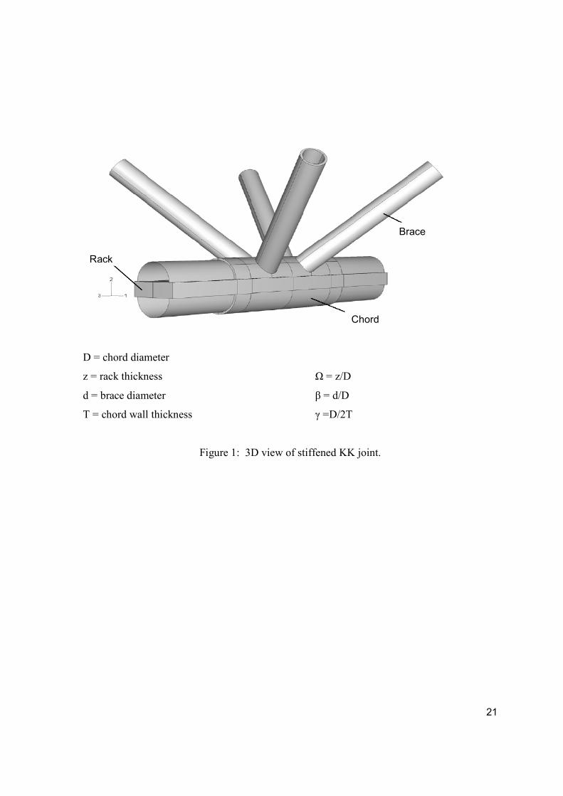
planar joints. This parametric study involves a stress analysis of a rack plate stiffened multi-
planar KK joint as shown in Figure 1.
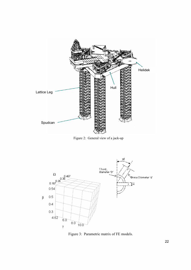
The stiffened multi-planar KK joint under investigation is an integral part of the lattice legs
of a jack-up platform as can be observed from Figure 2. Each leg is a critical component of
the jack-up as failure of one leg will lead to the collapse of the whole structure. An extensive
understanding of possible crack sites in the KK joint, which is to be achieved by this study, is
a first step to prevent an eventual collapse of the platform.
A finite element analysis of over 120 models utilizing a combination of 3D solid elements
and 2D shell elements was employed for the purpose of this work with the ultimate goal of
developing parametric Stress Concentration Factor (SCF) equations to represent the hot spot
stress at the brace/chord intersection and any other location identified as a potential hot spot.
3
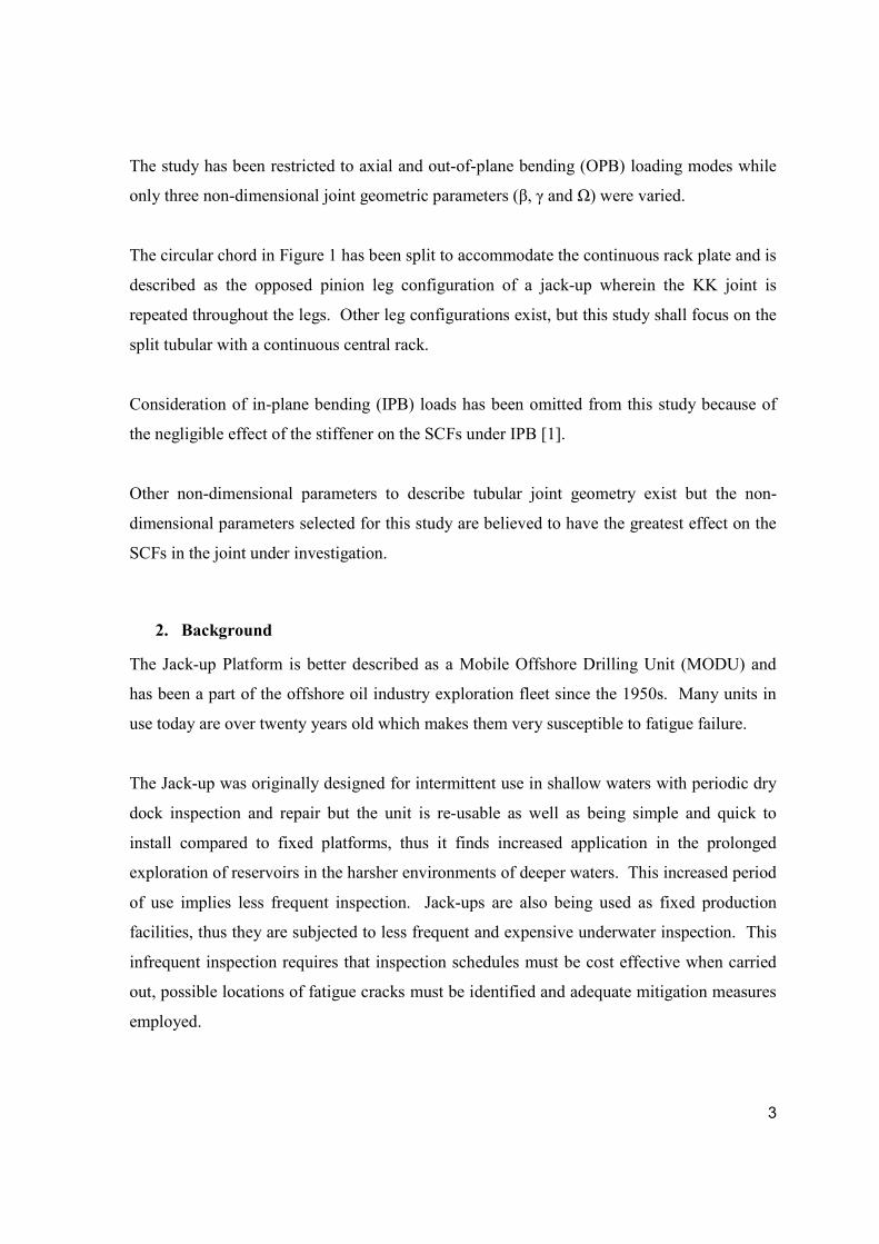
The study has been restricted to axial and out-of-plane bending (OPB) loading modes while
only three non-dimensional joint geometric parameters (β, γ and Ω) were varied.
The circular chord in Figure 1 has been split to accommodate the continuous rack plate and is
described as the opposed pinion leg configuration of a jack-up wherein the KK joint is
repeated throughout the legs. Other leg configurations exist, but this study shall focus on the
split tubular with a continuous central rack.
Consideration of in-plane bending (IPB) loads has been omitted from this study because of
the negligible effect of the stiffener on the SCFs under IPB [1].
Other non-dimensional parameters to describe tubular joint geometry exist but the non-
dimensional parameters selected for this study are believed to have the greatest effect on the
SCFs in the joint under investigation.
2. Background
The Jack-up Platform is better described as a Mobile Offshore Drilling Unit (MODU) and
has been a part of the offshore oil industry exploration fleet since the 1950s. Many units in
use today are over twenty years old which makes them very susceptible to fatigue failure.
The Jack-up was originally designed for intermittent use in shallow waters with periodic dry
dock inspection and repair but the unit is re-usable as well as being simple and quick to
install compared to fixed platforms, thus it finds increased application in the prolonged
exploration of reservoirs in the harsher environments of deeper waters. This increased period
of use implies less frequent inspection. Jack-ups are also being used as fixed production
facilities, thus they are subjected to less frequent and expensive underwater inspection. This
infrequent inspection requires that inspection schedules must be cost effective when carried
out, possible locations of fatigue cracks must be identified and adequate mitigation measures
employed.
4
Typical jack-up units consist of a buoyant triangular platform supported by three independent
lattice legs, each resting on a large inverted conical footing known as a spud can. These are
generally fabricated from High Strength weldable steel. High Strength Steel (HSS) bestows a
high strength to weight ratio on the jack-up but is susceptible to Hydrogen Assisted Cracking
(HAC) which is linked to the presence of welding defects, seabed Sulphate Reducing
Bacteria (SRB) and the levels of applied cathodic protection [2].
The lattice legs of Jack-ups are a truss-work of chords, braces and span breakers (Figure 2).
The braces provide the shear capacity of the legs while the chords provide the axial and
flexural stiffness. The tubular members of the jack-up legs are joined in different
configurations to produce T, Y, K or X joints in either uni-planar or multi-planar
configurations. These joints are differentiated by the mode of load transfer exhibited.
Chiew et al [3] conducted a numerical and experimental stress analysis of a tubular XT joint
and identified that the multi-planar effects in tubular joints can be categorised into multi-
planar carry-over effects and multi-planar stiffness effects. The carry-over effect was
attributed to the load interference to the in-plane brace members from the loading on the out-
of-plane brace members and vice versa. The SCFs at the intersection of the in-plane brace
members and the chord were described as carry-over SCFs. On the other hand, the presence
of out-of-plane braces increases the total stiffness and load carrying capacity of the entire
joint. This results in a decrease in the stress concentration at the loaded brace members and
is described as the multi-planar stiffness effect. It was also observed that carry-over effects
are negligible under IPB but become more pronounced under OPB and even to a greater
extent under axial loads. In general it was concluded that the magnitude of the multi-planar
effects depends on the load patterns and the relative geometrical locations of the brace
members.
The lack of design guidelines for multi-planar joints in most codes results in a plane by plane
assessment of the joints by designers, thus the effects of restraints and loads from other
braces are ignored. Lee and Wilmsburst [4] identified that this practice can be either over
conservative or grossly unsafe. Joop et al [5] proposed the application of a multi-planar
5
coefficient to the uni-planar joint capacity in order to estimate the ultimate strength of multi-
planar joints. This approach was found to adequately account for the multi-planar effects in
the joint.
Ramachandra et al [6] investigated the effect of internal ring stiffeners on the strength of
tubular T and Y joints. The results of the experimental approach adopted for the problem
revealed that the provision of three stiffeners in axially loaded T joints resulted in a 58.8%
reduction of the maximum SCF in the chord and a 69.9% reduction in the brace. A 50%
reduction was obtained in both the chord and the brace of an axially loaded Y joint. Lee and
Llewelyn-Parry [7] utilised the finite element method for a problem similar to that
investigated by Ramachandra but considered T and DT joints. Although internal ring
stiffeners do not significantly affect the ductility of tubular joints they recommend that
stiffeners positioned at the saddle position provide a better strength enhancement than those
at the crown positions. The experimental investigation of Thandavamoorthy [8] revealed that
bending of the chord of internally ring stiffened joints was the predominant mode of
deformation as opposed to ovalising and punching shear of unstiffened joints.
A parametric study on the ultimate load carrying capacity of doubler plate reinforced T joints
was executed by Chan et al [9]. A 150% increase in ultimate strength was observed for
axially loaded joints while a 75% increase was observed for joints loaded in bending.
Myers et al [1] investigated the effect of rack plates on T and Y, in particular the influence
on the SCF of three different longitudinal stiffeners. The constant thickness continuous
stiffener returned the best performance when compared to the dual thickness stiffener
(rack/rib plate) and the non-continuous stiffener. A 50% reduction in the maximum SCF was
approached under axial loading, 20% reduction under out-of-plane bending while the peak
SCF was unaffected by in-plane bending. The mechanism of operation of the longitudinal
stiffener was observed to be the restraining of chord wall radial deformation, with thicker
rack plates providing an additional restraint to chord deformation in the direction of the brace
axis.
6
3. Scope and Definition of the Parametric Study
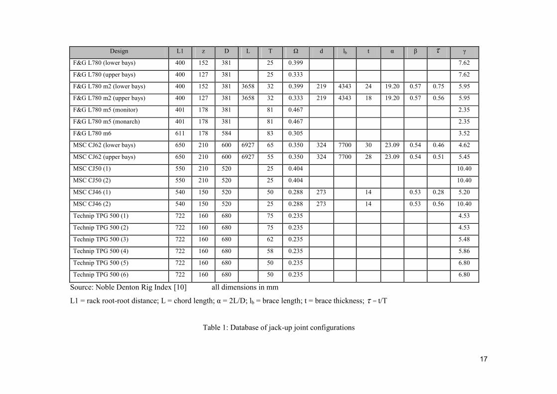
To ensure that the results of this study would be representative of the geometries found in
practice an extensive review was conducted of Jack up joint geometries using the Noble
Denton Rig Index [10] along with other information supplied by the Offshore Industry. A
summary of this information is presented in Table 1.
Figure 3 depicts the grid of geometric parameters selected for the study as well as the load
cases considered. Due to limitations in time and resources the study has been restricted to
axial and out-of-plane bending (OPB) loading modes while only three non-dimensional joint
geometric parameters (β, γ and Ω) were varied.
The non-dimensional parameters ranges are:
0.3 ≤ β ≤ 0.54
4.62 ≤ γ ≤ 10
0.167 ≤ Ω ≤ 0.467
Four values for each non-dimensional parameter were chosen roughly equally spaced in each
parametric range giving a total of sixty-four possible combinations per load case and a total
of one hundred and twenty-eight models would be employed for the parametric study. Other
non-dimensional parameters were kept constant and all values defined for MSC CJ62 (upper
bays) are given in Table 1.
Consideration of IPB was omitted from this study because of the negligible effect of the
stiffener on the SCFs under such a load as reported by Myers et al [1]. The non-dimensional
parameters selected for this study are believed to have the greatest effect on the SCFs for the
stiffened multiplanar KK joint under investigation.
4. Finite Element Analysis of Multi-planar KK Joints
The parametric study was preceded by model validation analyses which successfully justified
the boundary conditions and mesh refinement. The general effect of the longitudinal
7
stiffener was also investigated in that a reduction in the SCF was anticipated, hence an
unstiffened full joint was analysed and compared with the stiffened full joint.
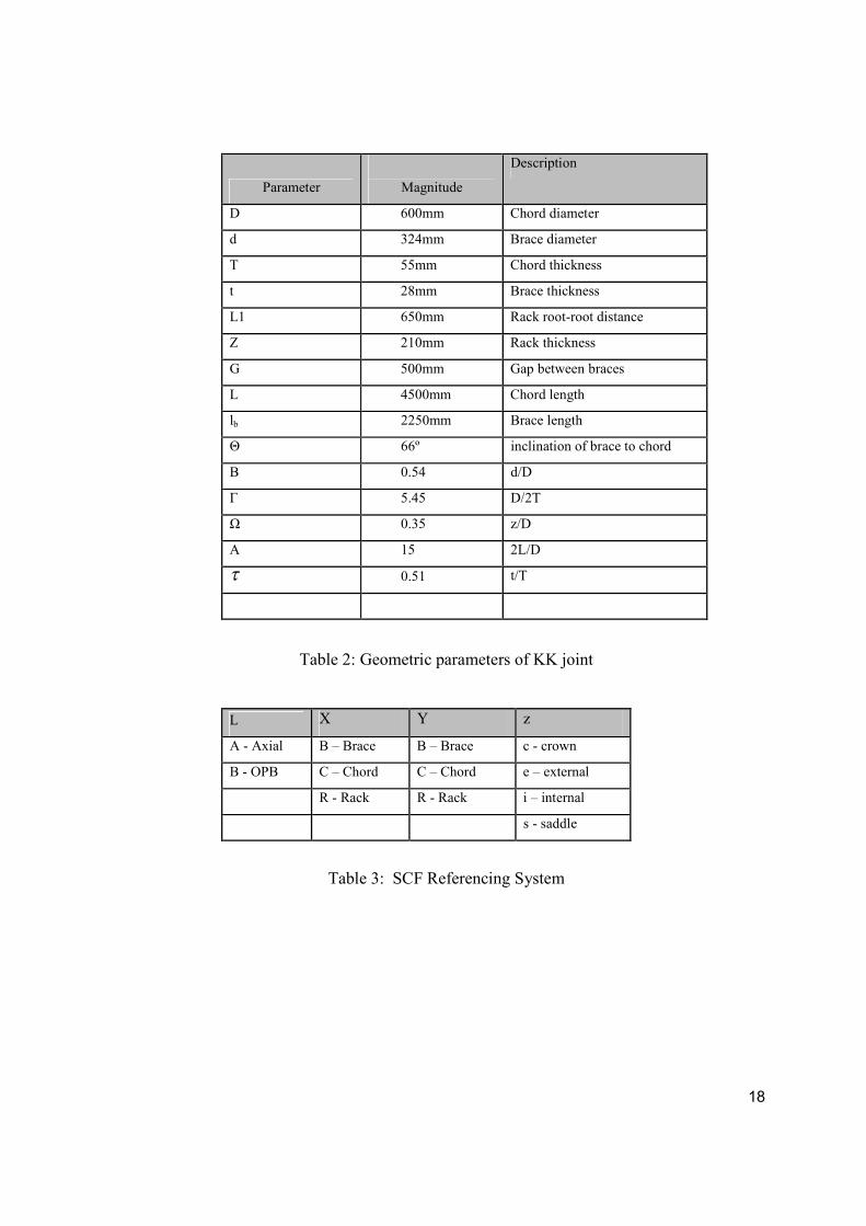
The complete details of a stiffened KK joint as found in MSC CJ62 (upper bays) are given in
Table 2. The details of the FE mesh optimisation, refinement and convergence analyses can
be found in reference [11]. In addition, several studies were conducted to verify the
approach used against published solutions for uni-planar tubular joints [9, 12].
Element C3D20R from the ABAQUS family of 3D stress elements were used with reduced
integration element control for meshing the joint area. This element is a 20 noded quadratic-
brick element. Element S8R from the ABAQUS family of shell elements was used with
reduced integration for meshing the shell section of the joint. It is an 8-noded doubly curved
thick shell element with 6 degrees of freedom per node. In each case a convergence study
was undertaken to optimise the mesh element density. An example of the results of one such
study for the chord saddle SCF under axial tension is:
10 12 14 16 18 (Number of elements at brace/chord intersection)
5.574 5.555 5.517 5.505 5.502 (SCF)
To validate the technique, several related geometries were modelled and compared with
results in the published literature. The results obtained were compared with Efthymiou and
LR parametric equations as well as with the available SCF database [14]. An example of one
such comparison for an unstiffened tubular T joint under axial and In-Plane Bending (IPB) is
shown below:
Load Case Efthymiou [14] LR [14] Database [14] FEA
Axial 5.363 4.942 5.700 5.502
IPB 2.328 2.028 2.000 2.324
8
From the comparison above, it can be observed that the Efthymiou parametric equation [14]
gives the best agreement with the present FEA results for all load cases and acceptable
agreement with the LR equation and SCF database [14].
The stiffened model returned an internal SCF at the chord side of the chord/rack intersection
under axial load. The rack plate appeared to have the following effects: it restrained the
transverse deformation along the longitudinal axis and also reduced the radial deformation of
the chord wall. The opposition to the radial deformation of the chord wall introduced by the
rack plate created an internal tensile stress state which resulted in the internal SCF.
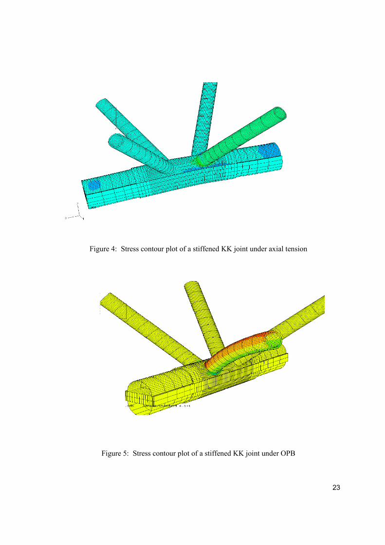
Figures 4 and 5 show stress contour plots of a stiffened KK joint under axial and OPB,
respectively. Under OPB load, the hot spot occurred at the same location and the general
mode of deformation remained similar to that for the unstiffened joint except that a lower
SCF was observed for the stiffened case. The rack plate introduced some additional stiffness
to the chord wall and hence resulted in the lower SCF.
5. Results and Discussion
Three critical SCF locations were identified for each of the load cases investigated and
suitable expressions to adequately describe the locations identified have also been
established.
For the axial load study comprising sixty-four different models, the location of maximum
stress concentration changed from model to model as the geometric parameters of the joint
were varied. One internal SCF was observed in the vicinity of the chord/rack intersection
while two external SCFs were noticed at the brace/chord intersection. For the OPB study,
one internal SCF was observed in the vicinity of the brace/chord intersection, one external
SCF at the chord/rack intersection and one external SCF at the brace/chord intersection.
A referencing system was adopted to identify the various SCF locations given as SCFL- XYz.
Subscript ‘L’ represents the load case and X Y and z are given in Table 3.
9
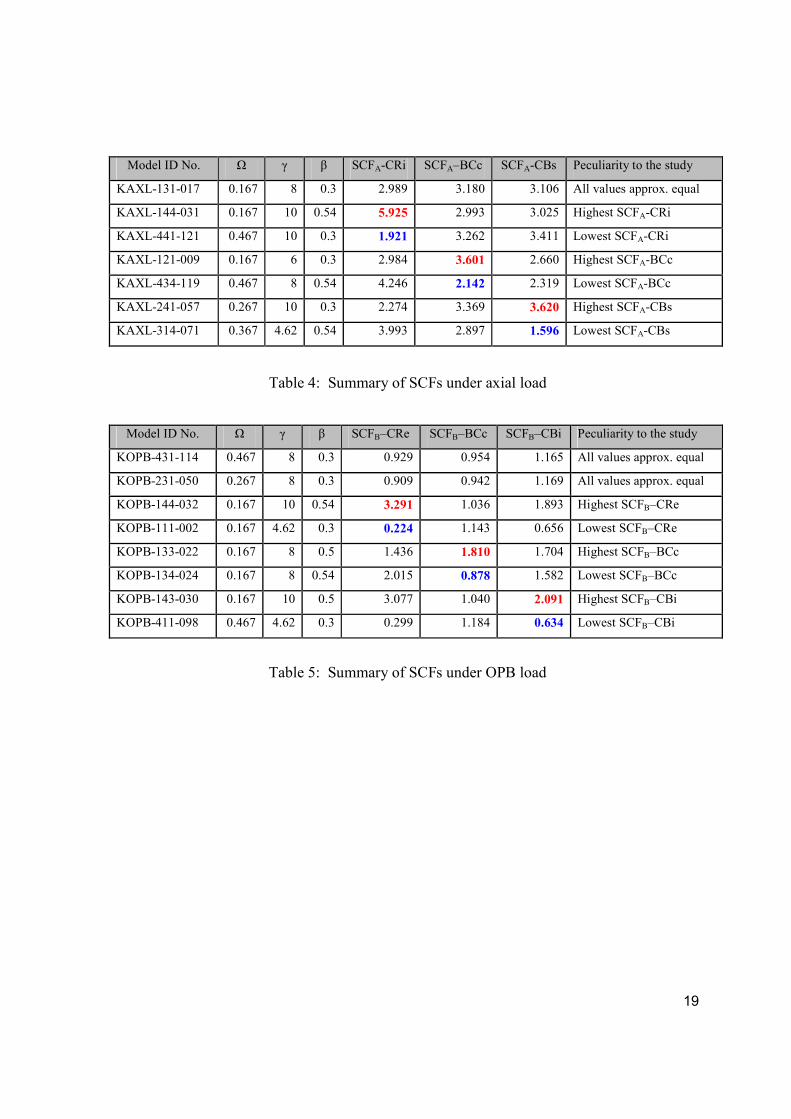
SCF Results for Axial Load
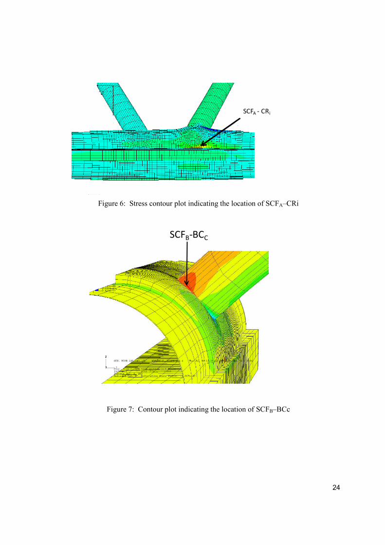
The internal SCF location identified under axial load is referred to as SCFA–CRi. This
indicates that an internal hot spot was observed at the chord side of the chord/rack
intersection. Figure 6 shows a contour plot which indicates the location as SCFA–CRi.
The external SCFs identified under axial load have respectively been referenced as SCFA–
BCc and SCFA–CBs. SCFA–BCc represents the external SCF observed at the crown heel on
the brace side of the brace/chord intersection. An external hot spot was identified in between
the saddle and crown but with greater proximity to the saddle. This location is referenced as
SCFA–CBs which indicates that the SCF was located on the chord side of the chord/brace
intersection. Table 4 summarises the SCF results under axial load.
The following general observations can be made under axial load:
The highest SCF is most likely found at an internal location in the vicinity of the
chord/rack intersection;
Low values of β produce low values of SCFA-CRi and vice versa for high β values;
Low values of Ω favour high values of SCFA-CRi while high values of Ω result in
low values of SCFA-CRi;
As γ increases, SCFA-CBs increases.
SCF Results for OPB Load
The internal SCF location identified under OPB has been referenced as SCFB–CBi. This
indicates that an internal hot spot was observed at the chord side of the chord/brace
intersection.
The external SCFs identified under OPB load have respectively been referenced as SCFB–
BCc and SCFB–CRe. SCFB–BCc represents the external SCF observed at the crown heel on
the brace side of the brace/chord intersection. The external hot spot identified on the chord
side of the chord/rack intersection has been referenced as SCFB–CRe. Figure 7 shows a
10
stress contour plot indicating the location of SCFB–BCc, and Table 5 summarises the OPB
results.
The following general observations can be made under OPB load:
As γ increases, both SCFB–CBi and SCFB–CRe increase;
Low values of β favour low values of SCFB–CRe and vice versa for high β values.
Validation of Results
There is little in the published domain to compare the results obtained. However, in order to
gain confidence in the present results, a number of checks have been carried out:
A detailed convergence study has been performed to ensure that the mesh used in the
study reasonably represents the SCF obtained experimentally or in practice. The
mesh adopted has been found to give good SCF results for a T joint when compared
with parametric equations; by extension this mesh should have returned good results
for the multi-planar joint.
The effect of the stiffener in a T joint has been examined and it has been observed
that ABAQUS [12] adequately captured the effect of the stiffener; by extension good
results should have been obtained for the stiffened KK joint.
Although the additional braces in a multi-planar joint introduce some stiffening effects,
Chiew et al [3] identified that the magnitude of the multi-planar effects depends on the load
patterns and the relative geometrical locations of the brace members. It is assumed that for
small values of β the stiffening effects would be minimized, thus the SCF in multi-planar
joints with low β values can be compared with that in equivalent uni-planar joints.
Parametric equations for unstiffened uni-planar K joints have been developed by Lloyds
Register and are contained in HSE OTH 354 [14].
11
The rack plate should act to reduce the stress concentration at the brace/chord intersection,
thus lower SCFs should be returned by the stiffened multi-planar KK joint when compared to
an unstiffened uni-planar K joint of similar geometric configuration.
The only SCF that can be compared is the SCFA-BCc as the Lloyds Register equations
provide only saddle SCFs under OPB. No saddle SCF was obtained under OPB in this study
and the SCF under axial load was not exactly at the saddle.
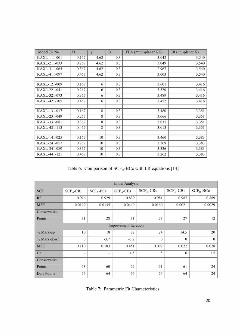
The results in Table 6 are as expected for γ values equal to 4.62 and 8. The results for γ
equal to 6 and 10 return minor deviations from the expected results as the FEA results are
slightly higher than those from LR equations. This deviation can be accepted because of the
approximations in geometry of the joints being considered, also remembering that the FEA
results for the unstiffened T joint were relatively higher than those predicted by the LR
equation.
The results generally confirm that the stiffener acts to reduce the SCF at the brace/chord
intersection, and the basis for comparing uni-planar joints with multi-planar joints can be
taken to be acceptable.
6. Development of Parametric Equations
The SCFs extracted from each model have been input into MINITAB [14] for regression
purposes while the non-dimensional parameters have been supplied as predictor variables.
The equations produced have been established by trial and error. The first sets of trials were
aimed at achieving model equations with good fit and minimal deviation from the data points
(SCFs). The six sets of SCFs extracted from the study have been found to display unique
dependence on the non-dimensional parameters.
The industrial relevance of this study and the results obtained meant improvement iterations
needed to be executed. These iterations required some trade-off between a good fit to the
data and marginal over-prediction of the SCFs by the equations. The improvement was
12
achieved by assessing the performance of the initial equations and then marking up the FEA
SCFs at all non-conservative points and marking down if required at conservative points.
The regression analysis was then performed with the refined data.
It was observed that poor initial R2 values yielded quite difficult improvement iterations,
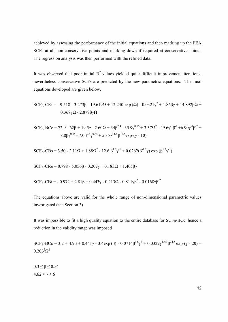
nevertheless conservative SCFs are predicted by the new parametric equations. The final
equations developed are given below.
SCFA-CRi = - 9.518 - 3.273β - 19.619Ω + 12.240 exp (Ω) - 0.0321γ2 + 1.86βγ + 14.892βΩ +
0.368γΩ - 2.879βγΩ
SCFA-BCc = 72.9 - 62β + 19.5γ - 2.60Ω + 34β2.4 - 35.9γ0.85 + 3.37Ω2 - 49.6γ-1β-1 +6.90γ-1β-2 +
8.8βγ0.85 - 7.0β2.4γ0.85 + 5.35γ0.65 β12.5exp-(γ - 10)
SCFA-CBs = 3.50 - 2.11Ω + 1.88Ω2 - 12.6 β1.2γ-1 + 0.0262(β-1.2γ) exp (β1.2γ-1)
SCFB-CRe = 0.798 - 5.056β - 0.207γ + 0.185Ω + 1.405βγ
SCFB-CBi = - 0.972 + 2.81β + 0.443γ - 0.213Ω - 0.811γβ2 - 0.0168γβ-2
The equations above are valid for the whole range of non-dimensional parametric values
investigated (see Section 3).
It was impossible to fit a high quality equation to the entire database for SCFB-BCc, hence a
reduction in the validity range was imposed
SCFB-BCc = 3.2 + 4.9β + 0.441γ - 3.4exp (β) - 0.0714β0.6γ2 + 0.0327γ1.65 β24.5 exp-(γ - 20) +
0.20β2Ω2
0.3 ≤ β ≤ 0.54
4.62 ≤ γ ≤ 6
13
0.267 ≤ Ω ≤ 0.467
The high values of R2 obtained indicate that good correlation exists between the predictor
and response variables in the different SCF equations. The number of conservative points for
the initial equations are about half of the total number of models considered. This implies
that the equations gave a mean fit rather than a conservative fit.
After the improvement iterations have been performed, the final equations are conservative
for more than 95% of the models analysed as can be inferred from Table 7. These equations
still adopt the same predictor variables as the initial equations.
7. Conclusion
A systematic parametric study covering various configurations of a rack plate stiffened multi-
planar KK joint has been executed using the finite element method. The KK joint under study
finds application especially in the leg structure of jack-up platforms. The rack plate works as
a stiffener which reduces the stress concentration at the brace/chord intersection, but other
hot spot sites are introduced into the joint. The rack is also used for raising and lowering of
the jack-up hull which gives the jack-up platform its peculiar jacking capabilities.
Over one hundred and twenty models using a combination of shell and solid elements have
been built and analysed with ABAQUS. Non-dimensional joint geometric parameters (β, γ
and Ω) have been employed in the present study. Stress analyses of the joint when subjected
to an axial load or to an OPB load have been preformed.
The finite element procedure employed was verified by comparing the SCF results obtained
against parametric SCF equations for unstiffened tubular joints, published in the available
literature. The basis for this comparison was the assumption that, as the stiffener thickness
and brace diameter decrease, the SCF for the joint under study should approach the SCF for
the equivalent unstiffened joint. Acceptable correlation was obtained in all cases considered.
14
Three critical SCF locations were identified for each load case, with each location becoming
the most critical based on the combination of the non-dimensional parameters selected for the
joint. The SCF values extracted from the models have been used to derive six sets of
parametric equations through multiple regression analysis performed using MINITAB. The
equations describe the SCF at the different locations as a function of the non-dimensional
ratios.
These equations have been produced for industrial application where safety and conservatism
take precedence over a perfect fit of the equations to the data points. Several improvement
iterations have therefore been performed in order to ensure that conservative SCFs are
predicted by the equations. In all cases, the final equations are conservative for more than
95% of the models analysed.
The literature search carried out revealed very little information on the particular joint
configuration studied, thus the critical SCF locations identified in this study could serve as a
guide to future reliability based inspection planning for jack-up platforms. The number of
non-dimensional parameters employed as well as the validity range of the equations
produced makes the equations best suited for structural optimisation prior to any extensive
design. These new design equations not only allow the rapid optimisation of multi-planar
joints but also can be used to quickly identify the location of maximum stress concentration
and hence the likely position of any fatigue cracks. This in itself is an invaluable tool for
planning NDT procedures and schedules.
8. References
[1] Myers P T, Brennan F P and Dover W D, “The Effect of Rack/rib Plate on the Stress
Concentration Factors in Jack-up chords”, Marine Structures, 14,485-505, 2001.
[2] Sharp J V, Billingham J and Robinson M J, “The Risk Management of High Strength
Steels in Jack-ups in Seawater”, Marine Structures 14, pp 537- 551, 2001.
15
[3] Chiew, Sing-Ping, Soh, Chee-Kiong, Wu, Nai-Wen, “Experimental and Numerical
Stress Analyses of Tubular XT-joint”, Journal of Structural Engineering, v 125, n 11,
Nov, 1999, p 1239-1248.
[4] Lee M.M.K and Wilmsburst S.R., “Parametric Study of Strength of Tubular Multi-
planar KK Joints”, Journal of Structural Engineering, Vol. 122 No.8, August 1996.
[5] Joop C.P, Yuji M and Yoshiaki K., “Ultimate Resistance of Unstiffened Multi-planar
Tubular TT and KK Joints”, Journal of Structural Engineering, Vol. 120 No.10,
October 1994.
[6] Ramachandra D S, Gandhi P, Raghava G and Madhava Rao A G., “Fatigue Crack
Growth in Stiffened Steel Tubular Joints in Seawater Environment”, Engineering
Structures 22, pp 1390–1401, 2000.
[7] Lee M M K and Llewelyn-Parry A, “Strength of ring-stiffened tubular T-joints in
offshore structures —a numerical parametric study”, Journal of Constructional Steel
Research 51, pp 239–264, 1999.
[8] Thandavamoorthy T S, “Experimental Investigation on Internally Ring-stiffened Joints
of Offshore Platforms”, Structural Engineering Research Centre IE Journal vol. 84,
August 2003.
[9] Chan T K, Fung T C, Tan C Y and Soh C K, “Behavior of Reinforced Tubular Joints”,
ICE proc. Issue 3, pp 263 274, 2001.
[10] Noble Denton Mobile Rig Index April 1992.
[11] Woghiren, C. O., “Parametric SCF Study of Longitudinally Stiffened Tubulars”, MSc
Thesis, University College London, 2006.
[12] Brennan F P, Peleties P and Hellier A K, “Predicting Weld Toe Stress Concentration
Factors for T and Skewed T-Joint Plate Connections”, Int. J of Fatigue pp 573-584,
2000.
[13] ABAQUS Version 6.4-4. Hibbit, Karlson and Sorensen Inc.
[14] Lloyd’s Register of Shipping, “Stress Concentration Factors for Simple Tubular Joints;
Assessment of existing and development of new parametric formulae”, HSE OTH 354
1997.

16
[15] MINITAB Release 14 Statistical Software. Minitab Inc, 3081 Enterprise Drive, State
Collge, PA 16801, USA.
17
Design L1 z D L T Ω d lb t α β γ
F&G L780 (lower bays) 400 152 381 25 0.399 7.62
F&G L780 (upper bays) 400 127 381 25 0.333 7.62
F&G L780 m2 (lower bays) 400 152 381 3658 32 0.399 219 4343 24 19.20 0.57 0.75 5.95
F&G L780 m2 (upper bays) 400 127 381 3658 32 0.333 219 4343 18 19.20 0.57 0.56 5.95
F&G L780 m5 (monitor) 401 178 381 81 0.467 2.35
F&G L780 m5 (monarch) 401 178 381 81 0.467 2.35
F&G L780 m6 611 178 584 83 0.305 3.52
MSC CJ62 (lower bays) 650 210 600 6927 65 0.350 324 7700 30 23.09 0.54 0.46 4.62
MSC CJ62 (upper bays) 650 210 600 6927 55 0.350 324 7700 28 23.09 0.54 0.51 5.45
MSC CJ50 (1) 550 210 520 25 0.404 10.40
MSC CJ50 (2) 550 210 520 25 0.404 10.40
MSC CJ46 (1) 540 150 520 50 0.288 273 14 0.53 0.28 5.20
MSC CJ46 (2) 540 150 520 25 0.288 273 14 0.53 0.56 10.40
Technip TPG 500 (1) 722 160 680 75 0.235 4.53
Technip TPG 500 (2) 722 160 680 75 0.235 4.53
Technip TPG 500 (3) 722 160 680 62 0.235 5.48
Technip TPG 500 (4) 722 160 680 58 0.235 5.86
Technip TPG 500 (5) 722 160 680 50 0.235 6.80
Technip TPG 500 (6) 722 160 680 50 0.235 6.80
Source: Noble Denton Rig Index [10] all dimensions in mm
L1 = rack root-root distance; L = chord length; α = 2L/D; lb = brace length; t = brace thickness; = t/T
Table 1: Database of jack-up joint configurations
18
Parameter Magnitude
Description
D 600mm Chord diameter
d 324mm Brace diameter
T 55mm Chord thickness
t 28mm Brace thickness
L1 650mm Rack root-root distance
Z 210mm Rack thickness
G 500mm Gap between braces
L 4500mm Chord length
lb 2250mm Brace length
Θ 66º inclination of brace to chord
Β 0.54 d/D
Γ 5.45 D/2T
Ω 0.35 z/D
Α 15 2L/D
0.51 t/T
Table 2: Geometric parameters of KK joint
L X Y z
A - Axial B – Brace B – Brace c - crown
B - OPB C – Chord C – Chord e – external
R - Rack R - Rack i – internal
s - saddle
Table 3: SCF Referencing System
19
Model ID No. Ω γ β SCFA-CRi SCFA–BCc SCFA-CBs Peculiarity to the study
KAXL-131-017 0.167 8 0.3 2.989 3.180 3.106 All values approx. equal
KAXL-144-031 0.167 10 0.54 5.925 2.993 3.025 Highest SCFA-CRi
KAXL-441-121 0.467 10 0.3 1.921 3.262 3.411 Lowest SCFA-CRi
KAXL-121-009 0.167 6 0.3 2.984 3.601 2.660 Highest SCFA-BCc
KAXL-434-119 0.467 8 0.54 4.246 2.142 2.319 Lowest SCFA-BCc
KAXL-241-057 0.267 10 0.3 2.274 3.369 3.620 Highest SCFA-CBs
KAXL-314-071 0.367 4.62 0.54 3.993 2.897 1.596 Lowest SCFA-CBs
Table 4: Summary of SCFs under axial load
Model ID No. Ω γ β SCFB–CRe SCFB–BCc SCFB–CBi Peculiarity to the study
KOPB-431-114 0.467 8 0.3 0.929 0.954 1.165 All values approx. equal
KOPB-231-050 0.267 8 0.3 0.909 0.942 1.169 All values approx. equal
KOPB-144-032 0.167 10 0.54 3.291 1.036 1.893 Highest SCFB–CRe
KOPB-111-002 0.167 4.62 0.3 0.224 1.143 0.656 Lowest SCFB–CRe
KOPB-133-022 0.167 8 0.5 1.436 1.810 1.704 Highest SCFB–BCc
KOPB-134-024 0.167 8 0.54 2.015 0.878 1.582 Lowest SCFB–BCc
KOPB-143-030 0.167 10 0.5 3.077 1.040 2.091 Highest SCFB–CBi
KOPB-411-098 0.467 4.62 0.3 0.299 1.184 0.634 Lowest SCFB–CBi
Table 5: Summary of SCFs under OPB load
20
Model ID No Ω γ Β FEA (multi-planar KK) LR (uni-planar K)
KAXL-111-001 0.167 4.62 0.3 3.042 3.540
KAXL-211-033 0.267 4.62 0.3 3.049 3.540
KAXL-311-065 0.367 4.62 0.3 2.967 3.540
KAXL-411-097 0.467 4.62 0.3 3.003 3.540
KAXL-121-009 0.167 6 0.3 3.601 3.416
KAXL-221-041 0.267 6 0.3 3.520 3.416
KAXL-321-073 0.367 6 0.3 3.489 3.416
KAXL-421-105 0.467 6 0.3 3.452 3.416
KAXL-131-017 0.167 8 0.3 3.180 3.351
KAXL-231-049 0.267 8 0.3 3.066 3.351
KAXL-331-081 0.367 8 0.3 3.031 3.351
KAXL-431-113 0.467 8 0.3 3.013 3.351
KAXL-141-025 0.167 10 0.3 3.460 3.383
KAXL-241-057 0.267 10 0.3 3.369 3.383
KAXL-341-089 0.367 10 0.3 3.336 3.383
KAXL-441-121 0.467 10 0.3 3.262 3.383
Table 6: Comparison of SCFA-BCc with LR equations [14]
Initial Analysis
SCF SCFA-CRi SCFA-BCc SCFA-CBs SCFB-CRe SCFB-CBi SCFB-BCc
R2 0.976 0.929 0.839 0.981 0.987 0.889
MSE 0.0199 0.0135 0.0440 0.0160 0.0021 0.0029
Conservative
Points 31 28 31 23 27 12
Improvement Iteration
% Mark-up 10 18 32 24 14.5 20
% Mark-down 0 -3.7 -3.2 0 0 0
MSE 0.110 0.183 0.451 0.092 0.022 0.028
Cp - - 4.5 5 6 1.5
Conservative
Points 63 60 62 61 61 24
Data Points 64 64 64 64 64 24
Table 7: Parametric Fit Characteristics
21
D = chord diameter
z = rack thickness Ω = z/D
d = brace diameter β = d/D
T = chord wall thickness γ =D/2T
Figure 1: 3D view of stiffened KK joint.
Brace
Chord
Rack
22
Figure 2: General view of a jack-up
Figure 3: Parametric matrix of FE models.
Helidek
Hull
Lattice Leg
Spudcan
Ω
β
γ
23
Figure 4: Stress contour plot of a stiffened KK joint under axial tension
Figure 5: Stress contour plot of a stiffened KK joint under OPB
24
SCFA-CRi
SCFA - CRi
Figure 6: Stress contour plot indicating the location of SCFA–CRi
SCFB-BCc
SCFB-BCC
Figure 7: Contour plot indicating the location of SCFB–BCc