Embed Size (px)
Citation preview
Weld Australia Technical Guidance Note
Weld Defects
TGN-PG01
www.weldaustralia.com.au
Weld Australia Technical Guidance Note | Weld Defects | © 2018 2
ForewordThis Technical Guidance Note is a revision of the Pocket Guide entitled Weld Defects originally published in 2002. Whilst the 2002 edition was based upon a guide originally developed by Alcoa of Australia Ltd, the current guide draws upon more recent publicly available material.
Future RevisionsThis Technical Guidance Note will be revised from time to time and comments aimed at improving its value to industry will be welcome. This publication is copyright and extracts from this publication shall not be reprinted or published without the Publisher’s express consent.
DisclaimerWhile every effort has been made and all reasonable care taken to ensure the accuracy of the material contained herein, the authors, editors and publishers of this publication shall not be held to be liable or responsible in any way whatsoever and expressly disclaim any liability or responsibility for any loss or damage costs or expenses howsoever caused incurred by any person whether the purchaser of this work or otherwise including but without in any way limiting any loss or damage costs or expenses incurred as a result of or in connection with the reliance whether whole or partial by any person as aforesaid upon any part of the contents of this Technical Guidance Note. Should expert assistance be required, the services of a competent professional person should be sought.
EditorMr Bruce CannonTechnical Publications Manager, Weld Australia
Weld AustraliaABN 69 003 696 526Building 3, Level 3, Pymble Corporate Centre20 Bridge Street, Pymble, NSW 2073PO Box 197, Macquarie Park BC, NSW 1670Phone: +61 (0)2 8748 0100www.weldaustralia.com.au
Weld Australia Technical Guidance Note | Weld Defects | © 2018 3
Contents
1.0 Introduction 52.0 Terminology 53.0 Imperfections 6
3.1 Cold Crack 63.2 Hot Crack 83.3 Lamellar Tear 103.4 Lack of Fusion 123.5 Lack of Penetration 143.6 Porosity and Wormholes 163.7 Uniform Porosity 183.8 Crater Pipe and Crack 193.9 Undercut 203.10 Overlap 213.11 Excessive Penetration 223.12 Excessive Reinforcement 233.13 Root Concavity 243.14 Inclusions 253.15 Imperfect Shape and Incorrect Size Weld 26
4.0 References 27Weld Australia Technical Notes 28
Weld Australia Technical Guidance Note | Weld Defects | © 2018 4
About Weld AustraliaWho We AreWeld Australia represents the welding profession in Australia. Our members are made up of individual welding professionals and companies of all sizes. Weld Australia members are involved almost every facet of Australian industry and make a significant contribution to the nation’s economy.
Our primary goal is to ensure that the Australian welding industry remains both locally and globally competitive, both now and into the future.
A not-for-profit, membership-based organisation, Weld Australia is dedicated to providing our members with a competitive advantage through access to industry, research, education, certification, government, and the wider industrial community.
Weld Australia is the Australian representative member of the International Institute of Welding (IIW).
Our MissionOur mission is to represent the interests of members and safeguard the public by ensuring the integrity of in-service welds, and to promote the use of best practice technology and quality systems.
Our Value PropositionWeld Australia generates revenue through its commercial activities which is then reinvested back into the welding community for the benefit of members.
Weld Australia brings individual and company members together to deliver:• A forum for the exchange of ideas and the sharing of resources• A voice to promote the interests of the welding community and shape the market for welding services• Specialist technical problem solving and a conduit between industry and research organisations• A pathway for learning and career development and the opportunity to benchmark against world’s
best practice
Our ServicesWeld Australia provides:
• Events and Seminars• Technical Publications• Technical Support and Advisory Services• Project Management• Professional Development• Qualification and Certification
Real Solutions to Real Problems…Weld Australia has a team of highly qualified welding engineers and technologists available to provide expert advisory services on all welding related matters. With expertise in a wide range of industries, ranging from biotechnology to heavy engineering we have a unique capability to solve your welding problems.
Our advice can help you substantially increase the operational life of your plant and equipment and thereby reduce your maintenance and repair overheads.
Further InformationFor further information about Weld Australia and how we can help your business, please visit: www.weldaustralia.com.au.
Weld Australia Technical Guidance Note | Weld Defects | © 2018 5
Weld Defects1.0 IntroductionThis Technical Guidance Note deals with the main defects found in fusion welds:
• made by using processes such as MMAW, GTAW, GMAW, FCAW and SAW;• in carbon, low alloy and high alloy steels;• in welded structures and equipment; and• during fabrication, inspection, repair and modification.
A weld defect is defined as an imperfection or group of imperfections which is outside the limits stated in the appropriate application standard whereas weld imperfections are flaws present in the weld metal or in the adjacent parent metal. They may or may not cause rejection of the weldment. A weld discontinuity is an imperfection detected during NDT techniques.
This Guidance Note is aimed at welders and welding supervisors as an easy-to-use practical consultative tool. Each weld defect is accompanied by a sketch and is discussed under the headings like description, causes, effects, prevention, detection, and repair.
2.0 TerminologyWelding related terminology used in Australia is published within the standard AS 2812 Welding, brazing and cutting of metals - Glossary of terms. This includes basic definitions of weld imperfections.
ISO publishes a variety of standards to define the welding related terminologies used in ISO standards with basic definitions for weld imperfections defined in ISO 6520-1 Welding and allied processes — Classification of geometric imperfections in metallic materials — Part 1: Fusion welding. In addition to the basic definitions, ISO 6520-1 assigns a numbering system to each imperfection which can be used in computer systems and in reports associated with ISO testing standards. They are also referenced within ISO 5817-1 Welding — Fusion-welded joints in steel, nickel, titanium and their alloys (beam welding excluded) — Quality levels for imperfections.
The basis for the ISO numbering system is the classification of imperfections into six main groups:• cracks;• cavities;• solid inclusions;• lack of fusion and penetration;• imperfect shape and dimension;• miscellaneous imperfections.
A three-figure reference number is used to describe the imperfection with a fourth digit used to describe sub-terms. A supplementary two digit alphabetic code can also be used to further define the cracking occurring during and after welding.
Throughout this Guidance Note, reference is made to both the AS 2812 definition reference number as well as the corresponding ISO term and reference number(s).
Weld Australia Technical Guidance Note | Weld Defects | © 2018 6
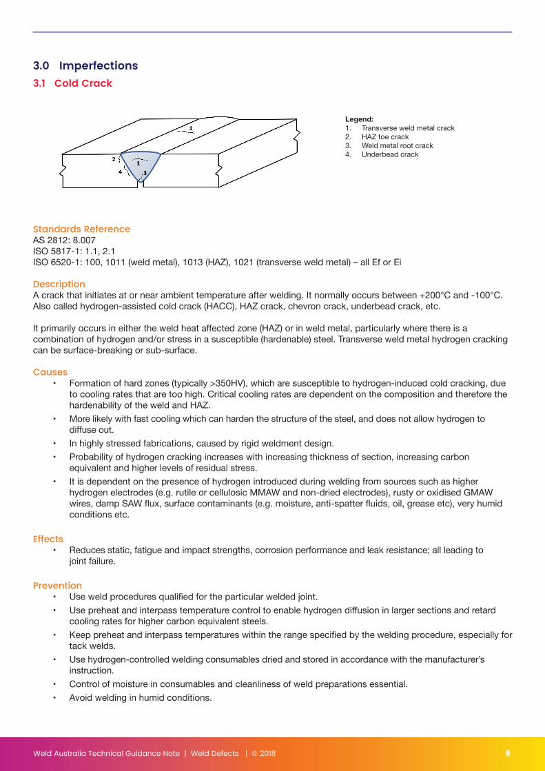
3.0 Imperfections3.1 Cold Crack
Standards ReferenceAS 2812: 8.007ISO 5817-1: 1.1, 2.1ISO 6520-1: 100, 1011 (weld metal), 1013 (HAZ), 1021 (transverse weld metal) – all Ef or Ei
DescriptionA crack that initiates at or near ambient temperature after welding. It normally occurs between +200°C and -100°C. Also called hydrogen-assisted cold crack (HACC), HAZ crack, chevron crack, underbead crack, etc.
It primarily occurs in either the weld heat affected zone (HAZ) or in weld metal, particularly where there is a combination of hydrogen and/or stress in a susceptible (hardenable) steel. Transverse weld metal hydrogen cracking can be surface-breaking or sub-surface.
Causes• Formation of hard zones (typically >350HV), which are susceptible to hydrogen-induced cold cracking, due
to cooling rates that are too high. Critical cooling rates are dependent on the composition and therefore the hardenability of the weld and HAZ.
• More likely with fast cooling which can harden the structure of the steel, and does not allow hydrogen to diffuse out.
• In highly stressed fabrications, caused by rigid weldment design.• Probability of hydrogen cracking increases with increasing thickness of section, increasing carbon
equivalent and higher levels of residual stress.• It is dependent on the presence of hydrogen introduced during welding from sources such as higher
hydrogen electrodes (e.g. rutile or cellulosic MMAW and non-dried electrodes), rusty or oxidised GMAW wires, damp SAW flux, surface contaminants (e.g. moisture, anti-spatter fluids, oil, grease etc), very humid conditions etc.
Effects• Reduces static, fatigue and impact strengths, corrosion performance and leak resistance; all leading to
joint failure.
Prevention• Use weld procedures qualified for the particular welded joint.• Use preheat and interpass temperature control to enable hydrogen diffusion in larger sections and retard
cooling rates for higher carbon equivalent steels.• Keep preheat and interpass temperatures within the range specified by the welding procedure, especially for
tack welds.• Use hydrogen-controlled welding consumables dried and stored in accordance with the manufacturer’s
instruction.• Control of moisture in consumables and cleanliness of weld preparations essential.• Avoid welding in humid conditions.
Legend:1. Transverse weld metal crack2. HAZ toe crack3. Weld metal root crack4. Underbead crack
Weld Australia Technical Guidance Note | Weld Defects | © 2018 7
• Use a balanced welding sequence to minimise residual stresses.• Avoid excessive restraint during fabrication.• Avoid movement of components while welding or during cooling.• Avoid large gaps.• Increased heat input may be beneficial.
Detection• Located in the weld’s HAZ (e.g. “underbead”) but can also occur in weld metal (e.g. chevron cracking,
transverse weld metal cracking).• Can be very difficult to detect since they may be sub-surface and very small (1-2 mm).• Severe cases might be detected visually or by sound.• Surface opening cracks can be detected by magnetic particle inspection or dye penetrant inspection.• Sub-surface defects can be found by ultrasonic examination and/or radiography depending on the size and
orientation of the defect.
NOTE: Subsurface transverse weld metal cracks can be difficult to detect due to the orientation of the cracks.
Permissible Levels• No cracks allowed in most welding standards.
Repair• Weld metal cracks are removed by gouging and grinding followed by re-welding with the correct welding
procedure.• HAZ cracks are more difficult to repair. Extensive gouging and grinding may be required with magnetic
particle inspection or dye penetrant inspection to ensure complete removal. Butter layers of weld metal may be required to build up locally to the best weld geometry. A weld procedure specific to the individual joint is advisable.
• Repair using a qualified low hydrogen weld procedure.• May require weld procedure utilising very low (H5) consumables.• May need hydrogen to be removed by heat treatment.
Further Reading1. Weld Australia’s Technical Note 12. Bailey et al, Welding steels without hydrogen cracking, Woodhead Publishing, 2nd edition 1993
Weld Australia Technical Guidance Note | Weld Defects | © 2018 8
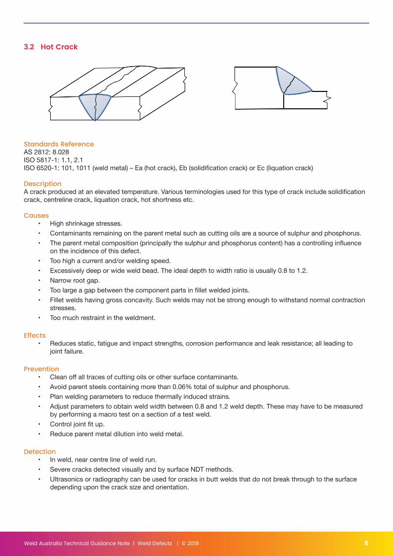
3.2 Hot Crack
Standards ReferenceAS 2812: 8.028ISO 5817-1: 1.1, 2.1ISO 6520-1: 101, 1011 (weld metal) – Ea (hot crack), Eb (solidification crack) or Ec (liquation crack)
DescriptionA crack produced at an elevated temperature. Various terminologies used for this type of crack include solidification crack, centreline crack, liquation crack, hot shortness etc.
Causes• High shrinkage stresses.• Contaminants remaining on the parent metal such as cutting oils are a source of sulphur and phosphorus.• The parent metal composition (principally the sulphur and phosphorus content) has a controlling influence
on the incidence of this defect.• Too high a current and/or welding speed.• Excessively deep or wide weld bead. The ideal depth to width ratio is usually 0.8 to 1.2.• Narrow root gap.• Too large a gap between the component parts in fillet welded joints.• Fillet welds having gross concavity. Such welds may not be strong enough to withstand normal contraction
stresses.• Too much restraint in the weldment.
Effects• Reduces static, fatigue and impact strengths, corrosion performance and leak resistance; all leading to
joint failure.
Prevention• Clean off all traces of cutting oils or other surface contaminants.• Avoid parent steels containing more than 0.06% total of sulphur and phosphorus.• Plan welding parameters to reduce thermally induced strains.• Adjust parameters to obtain weld width between 0.8 and 1.2 weld depth. These may have to be measured
by performing a macro test on a section of a test weld.• Control joint fit up.• Reduce parent metal dilution into weld metal.
Detection• In weld, near centre line of weld run.• Severe cracks detected visually and by surface NDT methods.• Ultrasonics or radiography can be used for cracks in butt welds that do not break through to the surface
depending upon the crack size and orientation.
Weld Australia Technical Guidance Note | Weld Defects | © 2018 9
Permissible Levels• No cracks allowed in most welding standards.
Repair• Repair using a qualified weld procedure.• Locally gouge and grind.• Thoroughly clean all surfaces in the weld area.• If the root cause is high sulphur or phosphorus steels, a low penetration or minimal dilution technique may
be required.

Weld Australia Technical Guidance Note | Weld Defects | © 2018 10
3.3 Lamellar Tear
Standards referenceAS 2812: 8.043ISO 5817-1: 1.1, 2.1ISO 6520-1: 101, 1014 (parent metal), – Ej (lamellar tear)
DescriptionCracking in the parent metal adjacent to the weld arising from weld stresses in the through thickness direction of the plate. The cracking usually occurs in a stepped configuration, associated with lamellar non-metallic inclusions in the plate, parallel to the fusion boundary.
Causes• They generally initiate either in the regions having a high-incidence of co-planar, stringer-like, non-metallic
inclusions or in areas subject to high residual stresses or both. Primarily occurred with ingot wrought steels with no special addition to reduce strains.
• Thermally induced strain in restrained joints resulting in high stresses through the thickness of the plate e.g. welds at corner, T-joint and cruciform joints.
• Incorrect joint design.
Effects• Reduces through section strength and leads to joint failure.
Prevention• Joints should be designed so that the weld contraction imposes the minimum of strain in the through
thickness direction e.g. slight gap between plates as in above sketch.• Continuous casting Z-plates should be used in critical cases. These are plates that are tested in the
through-thickness direction and have guaranteed minimum ductility in that direction.• Use vacuum-degassed steel.• Instead of rolled plate use forgings, extrusions or castings.• Weld sequence e.g. buttering to reduce stress perpendicular to plate grain.
Detection• Usually found by during ultrasonic examination.
Permissible Levels• No cracks allowed in most welding standards.
Repairs• Repair using a qualified welding procedure.
Weld Australia Technical Guidance Note | Weld Defects | © 2018 11
• One of the most extensive and difficult repairs. Large volumes of weld metal and parent plate usually have to be removed.
• Butter laying build up technique usually required for successful repair.• Maybe possible to add a doubler plate to “bypass” the defect.
Further Reading1. Weld Australia Technical Note 62. AS/NZS 1554.1 (Appendix H)
Weld Australia Technical Guidance Note | Weld Defects | © 2018 12
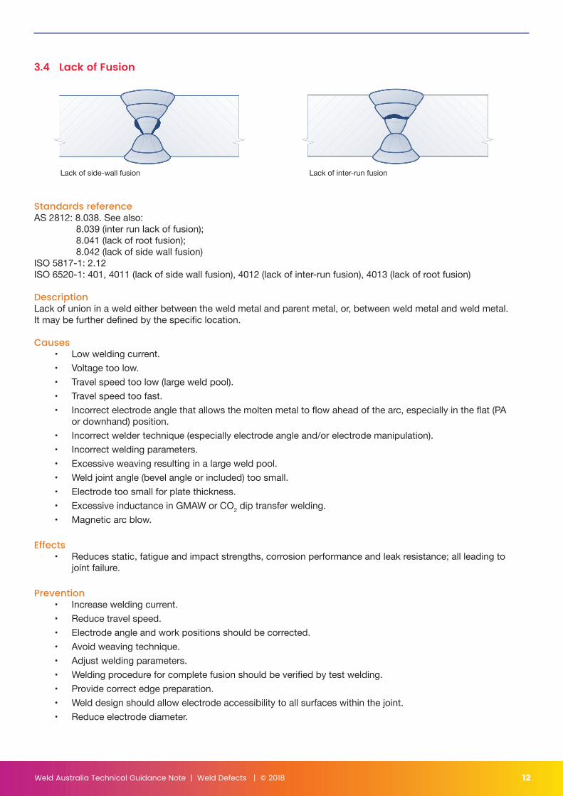
3.4 Lack of Fusion
Lack of side-wall fusion Lack of inter-run fusion
Standards referenceAS 2812: 8.038. See also: 8.039 (inter run lack of fusion); 8.041 (lack of root fusion); 8.042 (lack of side wall fusion) ISO 5817-1: 2.12ISO 6520-1: 401, 4011 (lack of side wall fusion), 4012 (lack of inter-run fusion), 4013 (lack of root fusion)
DescriptionLack of union in a weld either between the weld metal and parent metal, or, between weld metal and weld metal. It may be further defined by the specific location.
Causes• Low welding current.• Voltage too low.• Travel speed too low (large weld pool).• Travel speed too fast.• Incorrect electrode angle that allows the molten metal to flow ahead of the arc, especially in the flat (PA
or downhand) position.• Incorrect welder technique (especially electrode angle and/or electrode manipulation).• Incorrect welding parameters.• Excessive weaving resulting in a large weld pool.• Weld joint angle (bevel angle or included) too small.• Electrode too small for plate thickness.• Excessive inductance in GMAW or CO2 dip transfer welding.• Magnetic arc blow.
Effects• Reduces static, fatigue and impact strengths, corrosion performance and leak resistance; all leading to
joint failure.
Prevention• Increase welding current.• Reduce travel speed.• Electrode angle and work positions should be corrected.• Avoid weaving technique.• Adjust welding parameters.• Welding procedure for complete fusion should be verified by test welding.• Provide correct edge preparation.• Weld design should allow electrode accessibility to all surfaces within the joint.• Reduce electrode diameter.
Weld Australia Technical Guidance Note | Weld Defects | © 2018 13
• Excessive inductance in GMAW welding should be reduced even at the expense of increased spatter.• Reduce arc blow.
Detection• Ultrasonic testing, or depending on the angle of orientation of the defect, radiography testing can find lack
of fusion.
Permissible Levels• Not permitted or very limited in most standards.
Repair• Repair using a qualified welding procedure.• Gouge, grind and re-weld.• Extensive lack of fusion may require removal of the entire weld.
NOTE: It is important to remove sufficient additional material to allow correct joint geometry to be prepared.
Weld Australia Technical Guidance Note | Weld Defects | © 2018 14
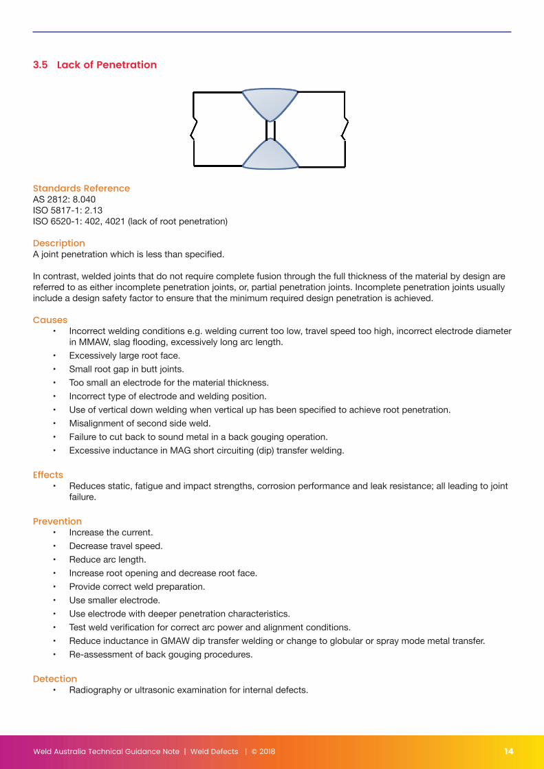
3.5 Lack of Penetration
Standards ReferenceAS 2812: 8.040ISO 5817-1: 2.13ISO 6520-1: 402, 4021 (lack of root penetration)
DescriptionA joint penetration which is less than specified.
In contrast, welded joints that do not require complete fusion through the full thickness of the material by design are referred to as either incomplete penetration joints, or, partial penetration joints. Incomplete penetration joints usually include a design safety factor to ensure that the minimum required design penetration is achieved.
Causes• Incorrect welding conditions e.g. welding current too low, travel speed too high, incorrect electrode diameter
in MMAW, slag flooding, excessively long arc length.• Excessively large root face.• Small root gap in butt joints.• Too small an electrode for the material thickness.• Incorrect type of electrode and welding position.• Use of vertical down welding when vertical up has been specified to achieve root penetration.• Misalignment of second side weld.• Failure to cut back to sound metal in a back gouging operation.• Excessive inductance in MAG short circuiting (dip) transfer welding.
Effects• Reduces static, fatigue and impact strengths, corrosion performance and leak resistance; all leading to joint
failure.
Prevention• Increase the current.• Decrease travel speed.• Reduce arc length.• Increase root opening and decrease root face.• Provide correct weld preparation.• Use smaller electrode.• Use electrode with deeper penetration characteristics.• Test weld verification for correct arc power and alignment conditions.• Reduce inductance in GMAW dip transfer welding or change to globular or spray mode metal transfer.• Re-assessment of back gouging procedures.
Detection• Radiography or ultrasonic examination for internal defects.
Weld Australia Technical Guidance Note | Weld Defects | © 2018 15
• Visual, magnetic particle and liquid penetrant for external or surface breaking defects.
Permissible Levels• Not permitted or very limited in most standards.
Repair• Complete weld removal by gouging is usually required. Difficulty may be experienced producing the correct
preparation geometry for re-welding if the joint cannot be separated. In these cases a GTAW (TIG root run) may be required. Re-weld the remainder of the joint with the specified consumable.
• Use a suitably qualified welding procedure.

Weld Australia Technical Guidance Note | Weld Defects | © 2018 16
3.6 Porosity and Wormholes
Standards ReferenceAS 2812: 8.058, see also 8.045 (linear porosity), 8.046) (localised porosity), 8.057 (piping porosity), 8.076 (uniformly distributed porosity), 8.078 (wormhole)ISO 5817-1: 2.3 (gas pore), 2.4 (clustered), 2.5 (linear), 2.6 (wormholes)ISO 6520-1: 2011 (gas pore), 2012 (uniformly distributed), 2013 (localised), 2014 (linear), 2016 (worm-hole), 2017 (surface pore), 2018 (surface porosity)
DescriptionPorosity in weld metal can be found in a number of different forms. Including its common form variants, it is typically described by its form and distribution as follows:
• Porosity: a number of gas pores in the weld metal, also referred to as uniformly distributed);• Wormhole: elongated or tubular cavity in the weld metal, also referred to as piping porosity;• Linear Porosity: line of gas pores substantially parallel to the axis of the weld;• Localised Porosity: an isolated group of gas pores. Also referred to as clustered porosity.
Causes• Gases absorbed into the weld pool e.g. oxygen, nitrogen, hydrogen.• A chemical imbalance in the molten weld due to loss of arc shielding from the atmosphere.• Welding through surface coatings e.g. paint, zinc etc.• Welding over a cavity or crevice gases become entrapped e.g. a Tee joint which is fillet welded on
both sides.• Excessive contamination from grease, dampness or the atmosphere.• Excessive voltage on FCAW wires.• Damp electrodes.• Occasionally caused by excessive sulphur in consumables or parent material.
Effects• Reduces static, fatigue and impact strengths with increased risk of leakage and failure.
Prevention• Eliminate the gas or cavities associated with the porosity.• Ensure good arc shielding.• Ensure gas flow, shroud size and shroud to workpiece distance is correct for gas shielded processes.• Ensure draft levels are low (<5kph wind speed) for gas shielded processes.• Do not use MMAW electrodes with damaged or cracked flux.• Remove surface contaminants such as grease, oil, rust and paint in the weld area.• Keep MMAW arcs as short as practicable and use weaving.• On FCAW processes, reduce the voltage in 0.5V increments to eliminate the problem, or preferably use the
manufacturer’s recommended voltage for the given amperage.• Use dried hydrogen-controlled consumables.• Do not use compressed air to clean the joint (oil contamination).
Weld Australia Technical Guidance Note | Weld Defects | © 2018 17
Detection• Best found by radiography or ultrasonic examination if sub-surface.• If surface breaking, usually visible during visual examination, otherwise detectable using magnetic particle or
liquid penetrant examination.
Permissible Levels• Due to its spheroidal shape, most standards consider small amounts of porosity relatively harmless.• Acceptable level of porosity varies with its form and end use. Refer to specific application standards.• Surface-breaking porosity that interferes with surface coatings, and porosity present at levels that potentially
mask other more serious imperfections and defects during an ultrasonic or radiographic examination are unacceptable.
Repair• When repair is required, a local gouge and grind is often sufficient. Avoid break-through of the weld or plate.
Re-weld taking precautions to avoid repeat problems.• Do not weld directly over porosity without removal first, as it often exacerbates the problem.• Repair using a qualified welding procedure.
NOTE: If it is necessary to weld through paint or other surface coatings, the weld procedure should be qualified by welding through a similar coated surface.
Weld Australia Technical Guidance Note | Weld Defects | © 2018 18
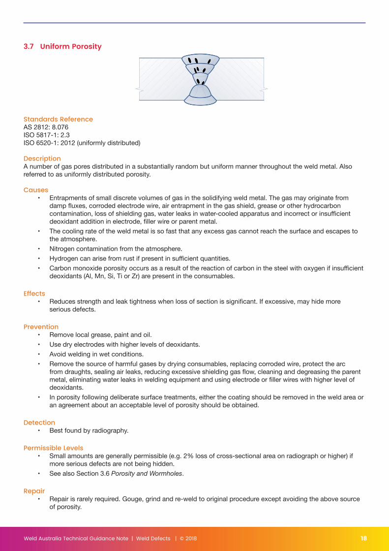
3.7 Uniform Porosity
Standards ReferenceAS 2812: 8.076ISO 5817-1: 2.3ISO 6520-1: 2012 (uniformly distributed)
DescriptionA number of gas pores distributed in a substantially random but uniform manner throughout the weld metal. Also referred to as uniformly distributed porosity.
Causes• Entrapments of small discrete volumes of gas in the solidifying weld metal. The gas may originate from
damp fluxes, corroded electrode wire, air entrapment in the gas shield, grease or other hydrocarbon contamination, loss of shielding gas, water leaks in water-cooled apparatus and incorrect or insufficient deoxidant addition in electrode, filler wire or parent metal.
• The cooling rate of the weld metal is so fast that any excess gas cannot reach the surface and escapes to the atmosphere.
• Nitrogen contamination from the atmosphere.• Hydrogen can arise from rust if present in sufficient quantities.• Carbon monoxide porosity occurs as a result of the reaction of carbon in the steel with oxygen if insufficient
deoxidants (Al, Mn, Si, Ti or Zr) are present in the consumables.
Effects• Reduces strength and leak tightness when loss of section is significant. If excessive, may hide more
serious defects.
Prevention• Remove local grease, paint and oil.• Use dry electrodes with higher levels of deoxidants.• Avoid welding in wet conditions.• Remove the source of harmful gases by drying consumables, replacing corroded wire, protect the arc
from draughts, sealing air leaks, reducing excessive shielding gas flow, cleaning and degreasing the parent metal, eliminating water leaks in welding equipment and using electrode or filler wires with higher level of deoxidants.
• In porosity following deliberate surface treatments, either the coating should be removed in the weld area or an agreement about an acceptable level of porosity should be obtained.
Detection• Best found by radiography.
Permissible Levels• Small amounts are generally permissible (e.g. 2% loss of cross-sectional area on radiograph or higher) if
more serious defects are not being hidden.• See also Section 3.6 Porosity and Wormholes.
Repair• Repair is rarely required. Gouge, grind and re-weld to original procedure except avoiding the above source
of porosity.
Weld Australia Technical Guidance Note | Weld Defects | © 2018 19
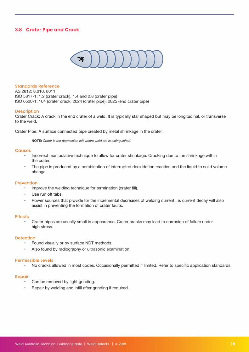
3.8 Crater Pipe and Crack
Standards ReferenceAS 2812: 8.010, 8011ISO 5817-1: 1.2 (crater crack), 1.4 and 2.8 (crater pipe)ISO 6520-1: 104 (crater crack, 2024 (crater pipe), 2025 (end crater pipe)
DescriptionCrater Crack: A crack in the end crater of a weld. It is typically star shaped but may be longitudinal, or transverse to the weld.
Crater Pipe: A surface connected pipe created by metal shrinkage in the crater.
NOTE: Crater is the depression left where weld arc is extinguished.
Causes• Incorrect manipulative technique to allow for crater shrinkage. Cracking due to the shrinkage within
the crater.• The pipe is produced by a combination of interrupted deoxidation reaction and the liquid to solid volume
change.
Prevention• Improve the welding technique for termination (crater fill).• Use run off tabs.• Power sources that provide for the incremental decreases of welding current i.e. current decay will also
assist in preventing the formation of crater faults.
Effects• Crater pipes are usually small in appearance. Crater cracks may lead to corrosion of failure under
high stress.
Detection• Found visually or by surface NDT methods.• Also found by radiography or ultrasonic examination.
Permissible Levels• No cracks allowed in most codes. Occasionally permitted if limited. Refer to specific application standards.
Repair• Can be removed by light grinding.• Repair by welding and infill after grinding if required.
Weld Australia Technical Guidance Note | Weld Defects | © 2018 20
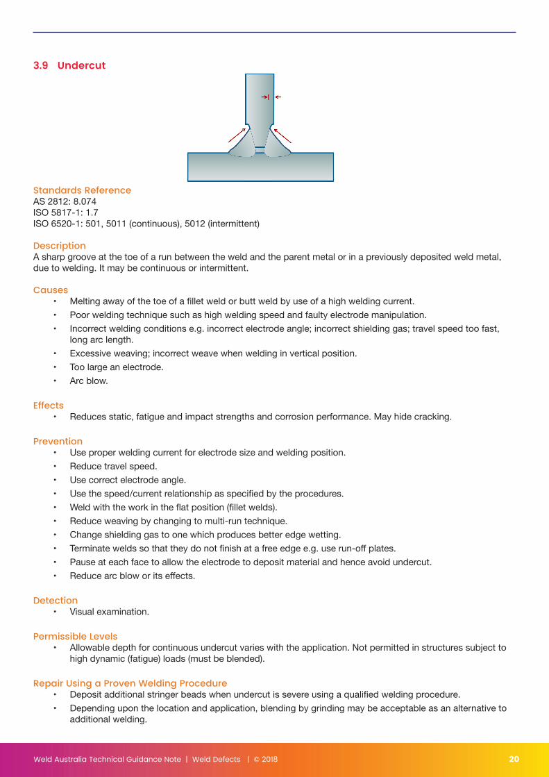
3.9 Undercut
Standards ReferenceAS 2812: 8.074ISO 5817-1: 1.7ISO 6520-1: 501, 5011 (continuous), 5012 (intermittent)
DescriptionA sharp groove at the toe of a run between the weld and the parent metal or in a previously deposited weld metal, due to welding. It may be continuous or intermittent.
Causes• Melting away of the toe of a fillet weld or butt weld by use of a high welding current.• Poor welding technique such as high welding speed and faulty electrode manipulation.• Incorrect welding conditions e.g. incorrect electrode angle; incorrect shielding gas; travel speed too fast,
long arc length.• Excessive weaving; incorrect weave when welding in vertical position.• Too large an electrode.• Arc blow.
Effects• Reduces static, fatigue and impact strengths and corrosion performance. May hide cracking.
Prevention• Use proper welding current for electrode size and welding position.• Reduce travel speed.• Use correct electrode angle.• Use the speed/current relationship as specified by the procedures.• Weld with the work in the flat position (fillet welds).• Reduce weaving by changing to multi-run technique.• Change shielding gas to one which produces better edge wetting.• Terminate welds so that they do not finish at a free edge e.g. use run-off plates.• Pause at each face to allow the electrode to deposit material and hence avoid undercut.• Reduce arc blow or its effects.
Detection• Visual examination.
Permissible Levels• Allowable depth for continuous undercut varies with the application. Not permitted in structures subject to
high dynamic (fatigue) loads (must be blended).
Repair Using a Proven Welding Procedure• Deposit additional stringer beads when undercut is severe using a qualified welding procedure.• Depending upon the location and application, blending by grinding may be acceptable as an alternative to
additional welding.
Weld Australia Technical Guidance Note | Weld Defects | © 2018 21
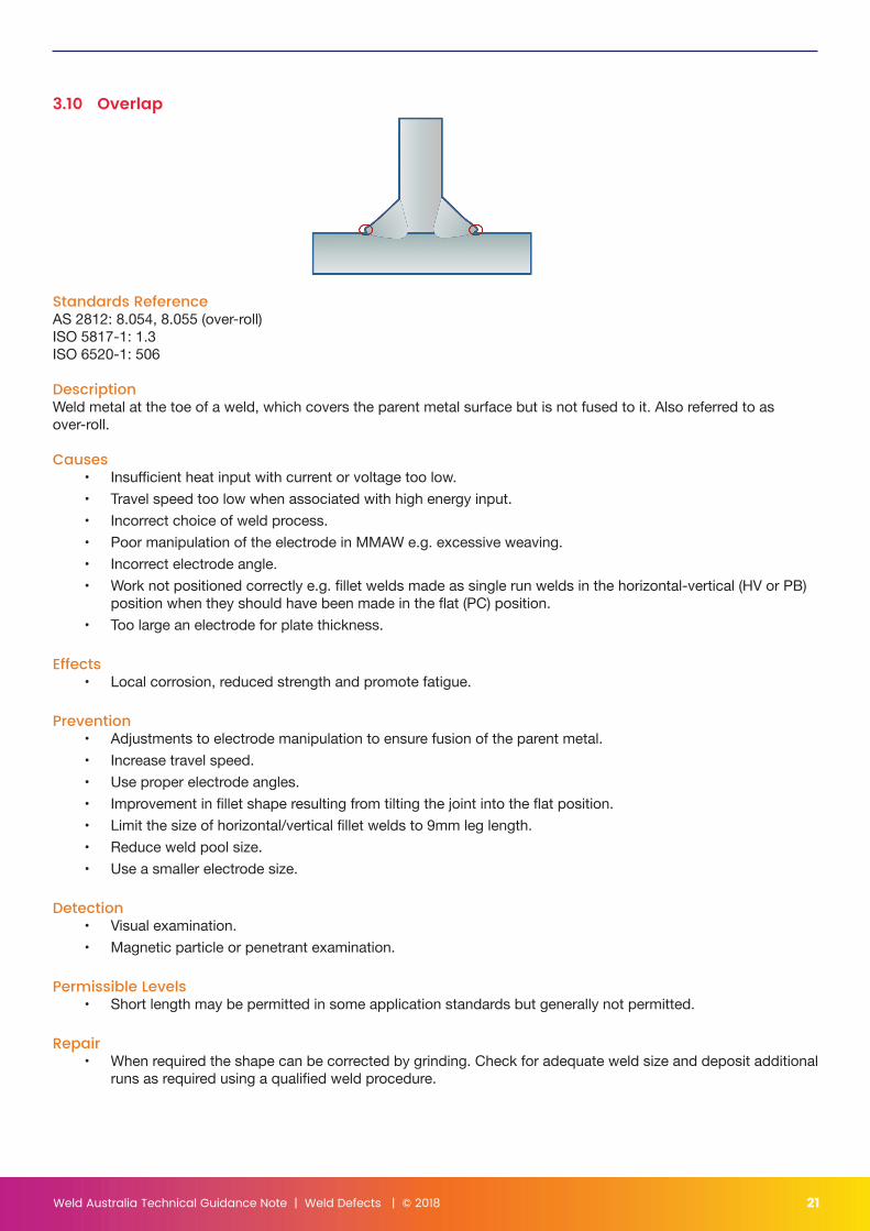
3.10 Overlap
Standards ReferenceAS 2812: 8.054, 8.055 (over-roll)ISO 5817-1: 1.3ISO 6520-1: 506
DescriptionWeld metal at the toe of a weld, which covers the parent metal surface but is not fused to it. Also referred to as over-roll.
Causes• Insufficient heat input with current or voltage too low.• Travel speed too low when associated with high energy input.• Incorrect choice of weld process.• Poor manipulation of the electrode in MMAW e.g. excessive weaving.• Incorrect electrode angle.• Work not positioned correctly e.g. fillet welds made as single run welds in the horizontal-vertical (HV or PB)
position when they should have been made in the flat (PC) position.• Too large an electrode for plate thickness.
Effects• Local corrosion, reduced strength and promote fatigue.
Prevention• Adjustments to electrode manipulation to ensure fusion of the parent metal.• Increase travel speed.• Use proper electrode angles.• Improvement in fillet shape resulting from tilting the joint into the flat position.• Limit the size of horizontal/vertical fillet welds to 9mm leg length.• Reduce weld pool size.• Use a smaller electrode size.
Detection• Visual examination.• Magnetic particle or penetrant examination.
Permissible Levels• Short length may be permitted in some application standards but generally not permitted.
Repair• When required the shape can be corrected by grinding. Check for adequate weld size and deposit additional
runs as required using a qualified weld procedure.
Weld Australia Technical Guidance Note | Weld Defects | © 2018 22
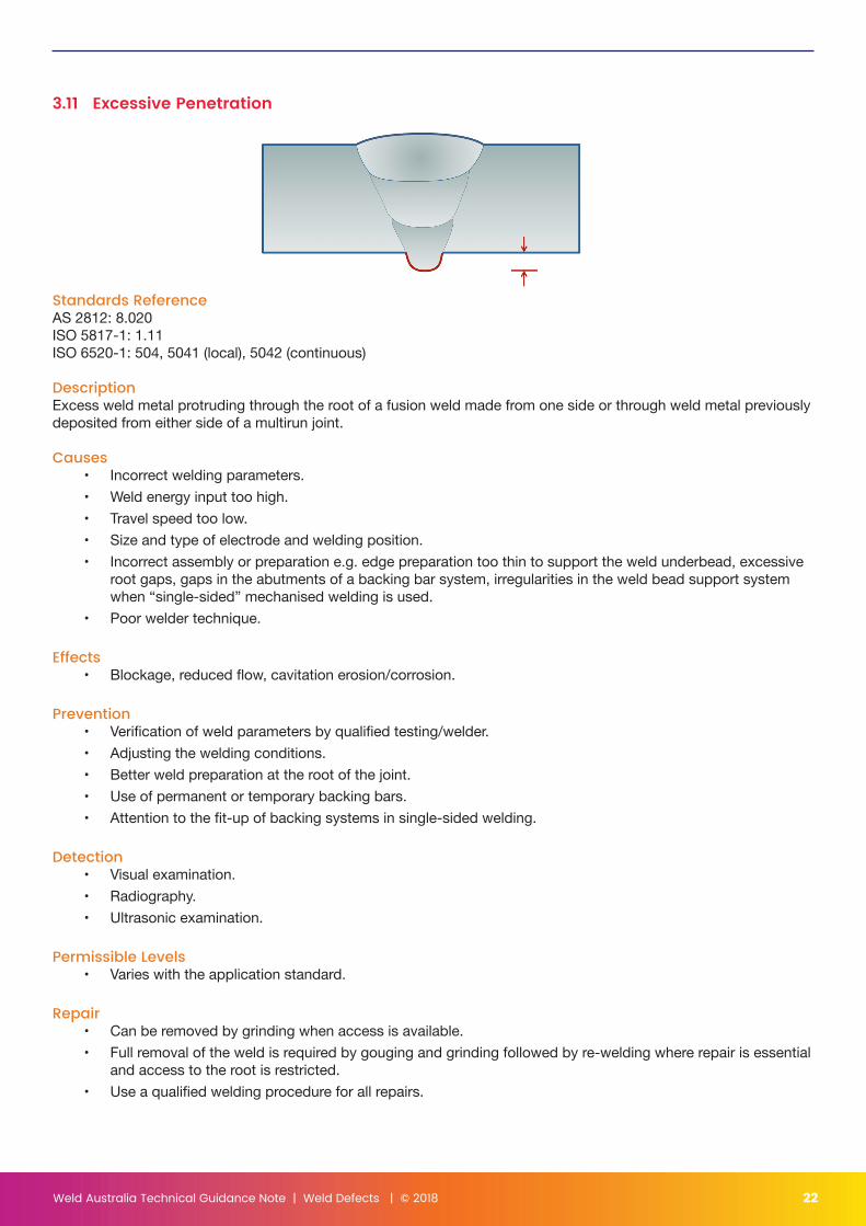
3.11 Excessive Penetration
Standards ReferenceAS 2812: 8.020ISO 5817-1: 1.11ISO 6520-1: 504, 5041 (local), 5042 (continuous)
DescriptionExcess weld metal protruding through the root of a fusion weld made from one side or through weld metal previously deposited from either side of a multirun joint.
Causes• Incorrect welding parameters.• Weld energy input too high.• Travel speed too low.• Size and type of electrode and welding position.• Incorrect assembly or preparation e.g. edge preparation too thin to support the weld underbead, excessive
root gaps, gaps in the abutments of a backing bar system, irregularities in the weld bead support system when “single-sided” mechanised welding is used.
• Poor welder technique.
Effects• Blockage, reduced flow, cavitation erosion/corrosion.
Prevention• Verification of weld parameters by qualified testing/welder.• Adjusting the welding conditions.• Better weld preparation at the root of the joint.• Use of permanent or temporary backing bars.• Attention to the fit-up of backing systems in single-sided welding.
Detection• Visual examination.• Radiography.• Ultrasonic examination.
Permissible Levels• Varies with the application standard.
Repair• Can be removed by grinding when access is available.• Full removal of the weld is required by gouging and grinding followed by re-welding where repair is essential
and access to the root is restricted.• Use a qualified welding procedure for all repairs.
Weld Australia Technical Guidance Note | Weld Defects | © 2018 23
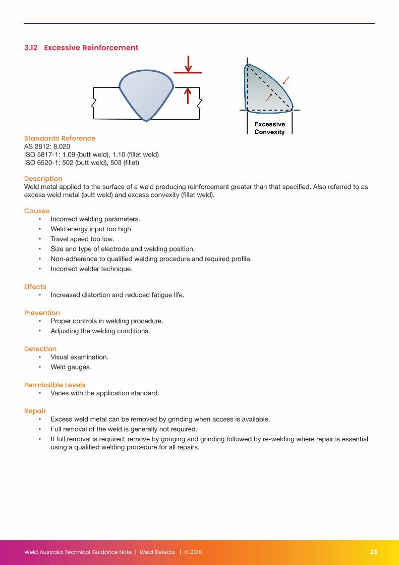
3.12 Excessive Reinforcement
Standards ReferenceAS 2812: 8.020ISO 5817-1: 1.09 (butt weld), 1.10 (fillet weld)ISO 6520-1: 502 (butt weld), 503 (fillet)
DescriptionWeld metal applied to the surface of a weld producing reinforcement greater than that specified. Also referred to as excess weld metal (butt weld) and excess convexity (fillet weld).
Causes• Incorrect welding parameters.• Weld energy input too high.• Travel speed too low.• Size and type of electrode and welding position.• Non-adherence to qualified welding procedure and required profile.• Incorrect welder technique.
Effects• Increased distortion and reduced fatigue life.
Prevention• Proper controls in welding procedure.• Adjusting the welding conditions.
Detection• Visual examination.• Weld gauges.
Permissible Levels• Varies with the application standard.
Repair• Excess weld metal can be removed by grinding when access is available.• Full removal of the weld is generally not required.• If full removal is required, remove by gouging and grinding followed by re-welding where repair is essential
using a qualified welding procedure for all repairs.
Weld Australia Technical Guidance Note | Weld Defects | © 2018 24
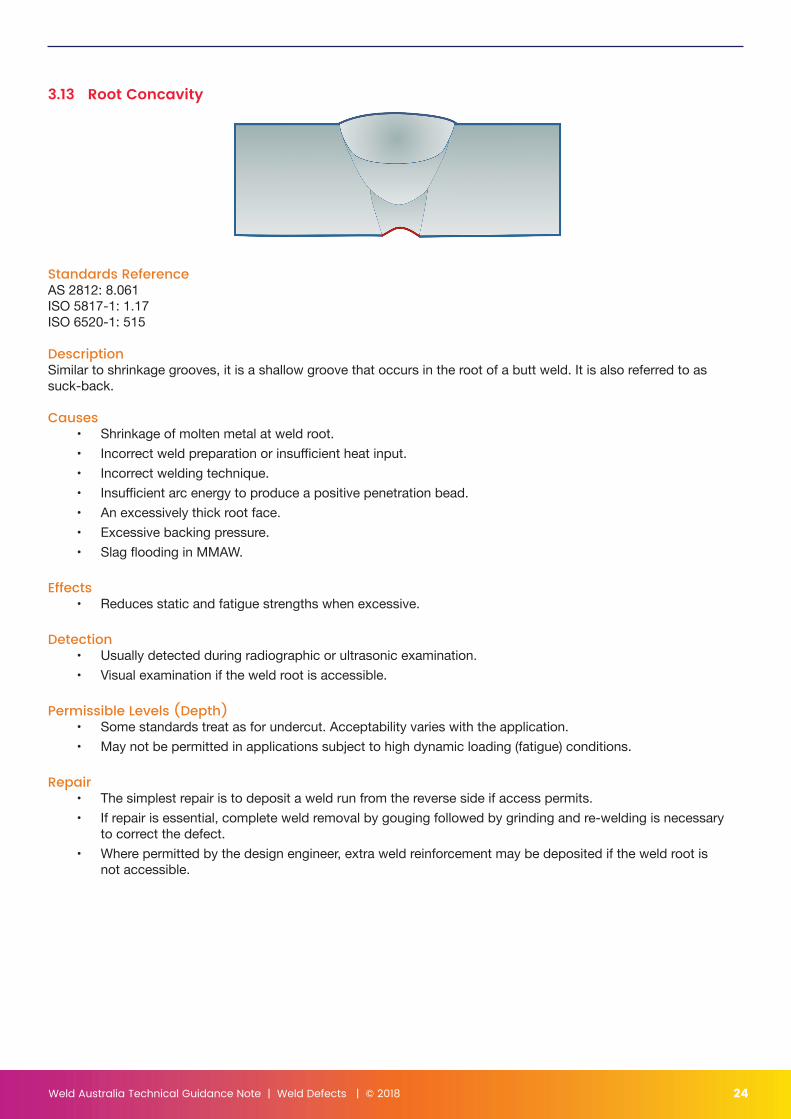
3.13 Root Concavity
Standards ReferenceAS 2812: 8.061ISO 5817-1: 1.17ISO 6520-1: 515
DescriptionSimilar to shrinkage grooves, it is a shallow groove that occurs in the root of a butt weld. It is also referred to as suck-back.
Causes• Shrinkage of molten metal at weld root.• Incorrect weld preparation or insufficient heat input.• Incorrect welding technique.• Insufficient arc energy to produce a positive penetration bead.• An excessively thick root face.• Excessive backing pressure.• Slag flooding in MMAW.
Effects• Reduces static and fatigue strengths when excessive.
Detection• Usually detected during radiographic or ultrasonic examination.• Visual examination if the weld root is accessible.
Permissible Levels (Depth)• Some standards treat as for undercut. Acceptability varies with the application.• May not be permitted in applications subject to high dynamic loading (fatigue) conditions.
Repair• The simplest repair is to deposit a weld run from the reverse side if access permits.• If repair is essential, complete weld removal by gouging followed by grinding and re-welding is necessary
to correct the defect.• Where permitted by the design engineer, extra weld reinforcement may be deposited if the weld root is
not accessible.
Weld Australia Technical Guidance Note | Weld Defects | © 2018 25
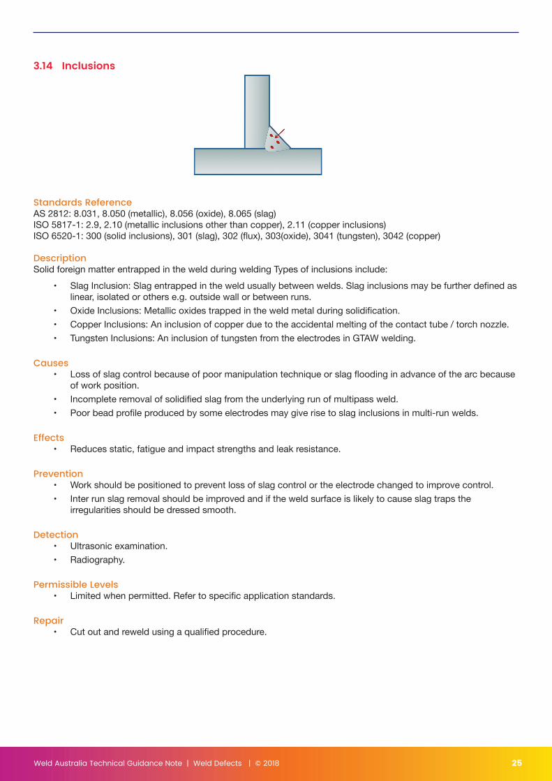
3.14 Inclusions
Standards ReferenceAS 2812: 8.031, 8.050 (metallic), 8.056 (oxide), 8.065 (slag)ISO 5817-1: 2.9, 2.10 (metallic inclusions other than copper), 2.11 (copper inclusions)ISO 6520-1: 300 (solid inclusions), 301 (slag), 302 (flux), 303(oxide), 3041 (tungsten), 3042 (copper)
DescriptionSolid foreign matter entrapped in the weld during welding Types of inclusions include:
• Slag Inclusion: Slag entrapped in the weld usually between welds. Slag inclusions may be further defined as linear, isolated or others e.g. outside wall or between runs.
• Oxide Inclusions: Metallic oxides trapped in the weld metal during solidification.• Copper Inclusions: An inclusion of copper due to the accidental melting of the contact tube / torch nozzle.• Tungsten Inclusions: An inclusion of tungsten from the electrodes in GTAW welding.
Causes• Loss of slag control because of poor manipulation technique or slag flooding in advance of the arc because
of work position.• Incomplete removal of solidified slag from the underlying run of multipass weld.• Poor bead profile produced by some electrodes may give rise to slag inclusions in multi-run welds.
Effects• Reduces static, fatigue and impact strengths and leak resistance.
Prevention• Work should be positioned to prevent loss of slag control or the electrode changed to improve control.• Inter run slag removal should be improved and if the weld surface is likely to cause slag traps the
irregularities should be dressed smooth.
Detection• Ultrasonic examination.• Radiography.
Permissible Levels• Limited when permitted. Refer to specific application standards.
Repair• Cut out and reweld using a qualified procedure.
Weld Australia Technical Guidance Note | Weld Defects | © 2018 26
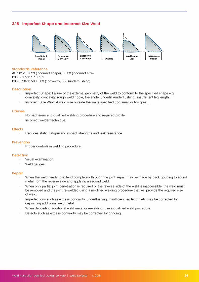
3.15 Imperfect Shape and Incorrect Size Weld
Standards ReferenceAS 2812: 8.029 (incorrect shape), 8.033 (incorrect size)ISO 5817-1: 1.10, 2.1ISO 6520-1: 500, 503 (convexity, 606 (underflushing)
Description• Imperfect Shape: Failure of the external geometry of the weld to conform to the specified shape e.g.
convexity, concavity, rough weld ripple, toe angle, underfill (underflushing), insufficient leg length.• Incorrect Size Weld: A weld size outside the limits specified (too small or too great).
Causes• Non-adherence to qualified welding procedure and required profile.• Incorrect welder technique.
Effects• Reduces static, fatigue and impact strengths and leak resistance.
Prevention• Proper controls in welding procedure.
Detection• Visual examination.• Weld gauges.
Repair• When the weld needs to extend completely through the joint, repair may be made by back gouging to sound
metal from the reverse side and applying a second weld.• When only partial joint penetration is required or the reverse side of the weld is inaccessible, the weld must
be removed and the joint re-welded using a modified welding procedure that will provide the required size of weld.
• Imperfections such as excess concavity, underflushing, insufficient leg length etc may be corrected by depositing additional weld metal.
• When depositing additional weld metal or rewelding, use a qualified weld procedure.• Defects such as excess convexity may be corrected by grinding.
Weld Australia Technical Guidance Note | Weld Defects | © 2018 27
4.0 ReferencesStandards referenced in this Guidance Note include the following:1. AS/NZS 1554 Structural steel welding Part 1: Welding of steel structures2. AS2812 Welding, brazing and cutting of metals — Glossary of terms3. ISO 5817 Welding — Fusion-welded joints in steel, nickel, titanium and their alloys (beam welding excluded) —
Quality levels for imperfections4. ISO 6520-1 Welding and allied processes — Classification of geometric imperfections in metallic materials —
Part 1: Fusion welding
Other references include the following:5. Bailey et al, Welding steels without hydrogen cracking, Woodhead Publishing, 2nd edition 1993
Weld Australia Technical Guidance Note | Weld Defects | © 2018 28
Weld Australia Technical NotesTN 1 - The Weldability of SteelsGives guidance on the preheat and heat input conditions (run size, current, voltage) required for acceptable welds and to avoid cold cracking in a wide variety of steels. The Note is applicable to a wide range of welding processes.
TN 2 - Successful Welding of AluminiumThis note covers the major welding processes as they are used for the welding and repair of aluminium and its alloys. Information is given on the processes, equipment, consumables and techniques. It also provides information on the range of alloys available and briefly covers safety, quality assurance, inspection and testing, costing and alternative joining processes.
TN 3 - Care and Conditioning of Arc Welding ConsumablesGives the basis and details for the correct care, storage and conditioning of welding consumables to control hydrogen and to ensure high quality welding.
TN 4 - The Industry Guide to Hardfacing for the Control of WearDescribes wear mechanisms and gives guidance on the selection of hardfacing consumables and processes for a wide range of applications. Includes Australian Hardfacing Suppliers Compendium 1998.
TN 5 - Flame Cutting of SteelsGives a wealth of practical guidance on flame cutting including detailed procedures for efficient cutting, selection of equipment and gases, practices for identifying and curing defective cutting, methods of maximising economy and other important guidance on the use of steels with flame cut surfaces.
TN 6 - Control of Lamellar TearingDescribes the features and mechanisms of this important mode of failure and the means of controlling tearing through suitable design, material selection, fabrication and inspection. Acceptance standards, repair methods, specification requirements and methods of investigation are proposed. Four appendices give details on the mechanism, material factors, tests for susceptibility and the important question of restraint.
TN 7 - Health and Safety in WeldingProvides information on all aspects of health and safety in welding and cutting. Designed to provide this information in such a way that it is readily useable for instruction in the shop and to provide guidance to management. Recommendations are given for safe procedures to be adopted in a wide variety of situations in welding fabrication.
TN 8 - Economic Design of WeldmentsPrinciples and guidance are given on methods and procedures for optimising design of weldments and welded joints and connections to maximise economy in welding fabrication. Factors influencing the overall cost of weldments which need to be considered at the design stage are discussed.
TN 9 - Welding Rate in Arc Welding Processes: Part 1 MMAWGives practical guidance and information on the selection of welding conditions to improve productivity during manual metal arc welding (MMAW). Graphs are provided showing rates as a function of weld size. The graphs enable a direct comparison of different types of welding electrodes when used for butt and fillet welds in various welding positions.
TN 10 - Fracture MechanicsProvides theory and gives practical guidance for the design and fabrication of structures, planning of maintenance and assessment of the likelihood of brittle or ductile initiation from flaws in ferrous and non-ferrous alloys. Engineering critical assessment case histories are discussed.
TN 11 - Commentary on the Structural Steel Welding Standard AS/NZS 1554The Note complements AS/NZS 1554 parts 1 to 7, by presenting background information which could not be
Weld Australia Technical Guidance Note | Weld Defects | © 2018 29
included in the Standard. It discusses the requirements of the Standard with particular emphasis on new or revised clauses. In explaining the application of the Standard to welding in steel construction, the commentary emphasises the need to rely on the provisions of the Standard to achieve satisfactory weld quality.
TN 12 - Minimising Corrosion in Welded Steel StructuresDesigned to provide practical guidance and information on corrosion problems associated with the welding of steel structures, together with possible solutions for minimising corrosion.
TN 13 - Stainless Steels for Corrosive Environments (A Joint publication with ACA)Provides guidance on the selection of stainless steels for different environments. Austenitic, ferritic and martensitic stainless steels are described together with the various types of corrosive attack. Aspects of welding procedure, design, cleaning and maintenance to minimise corrosion are covered.
TN 15 - Welding and Fabrication of Quenched and Tempered SteelProvides information on quenched and tempered steels generally available in Australia and gives guidance on welding processes, consumables and procedures and on the properties and performance of welded joints. Information is also provided on other fabrication operations such as flame cutting, plasma cutting, shearing and forming.
TN 16 - Welding Stainless SteelThis Technical Note complements Technical Note Number 13 by detailing valuable information on the welding of most types of stainless steels commonly used in industry.
TN 18 - Welding of CastingsProvides basic information on welding procedures for the welding processes used to weld and repair ferrous and non-ferrous castings. It also provides information on the range of alloys available and briefly covers non-destructive inspection, on-site heating methods and safety.
TN 19 - Cost Effective Quality Management for WeldingProvides guidelines on the application of the AS/NZS ISO 9000 series of Quality Standards within the welding and fabrication industries. Guidance on the writing, development and control of Welding Procedures is also given.
TN 20 - Repair of Steel PipelinesProvides an outline of methods of assessment and repair to a pipeline whilst allowing continuity of supply.
TN 21 - Submerged Arc WeldingProvides an introduction to submerged arc welding equipment, process variables, consumables, procedures and techniques, characteristic weld defects, applications and limitations. Describes exercises to explore the range of procedures and techniques with the use of solid wire (single and multiple arcs) and provides welding practice sheets, which may be used as instruction sheets to supplement demonstrations and class work, or as self-instruction units.
TN 22 - Welding Electrical SafetyProvides information and guidance on welding electrical safety issues: welding equipment, the body and the workplace.
TN 23 - Environmental Improvement GuidelinesProvides information and guidance on how to reduce consumption in the Welding and Fabrication industry, while reducing the impact on the environment at the same time.
TN 25 – Welding Specification for the Water IndustryPublished with the Water Services Association of Australia. Applies to all metal fabrication and repair work involving welding, carried out by a Water Agency (WA) and its Contractors/Subcontractors. Prescribes weld preparation, qualification of welding procedures and personnel, workmanship and inspection requirements for welds related to the arc welding by manual metal arc and other processes approved by the WA responsible Welding Coordinator.
Weld AustraliaABN 69 003 696 526
Building 3, Level 3, Pymble Corporate Centre20 Bridge Street, Pymble, NSW 2073
PO Box 197, Macquarie Park BC, NSW 1670Phone: +61 (0)2 8748 0100www.weldaustralia.com.au