Embed Size (px)
Citation preview
1
V 1.7
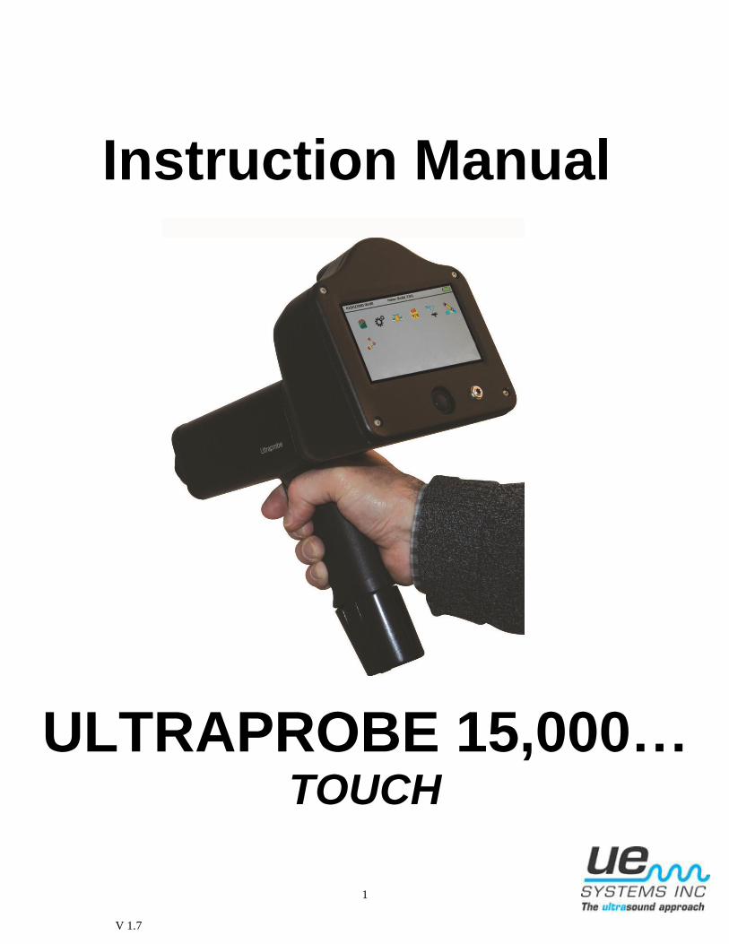
Instruction Manual
ULTRAPROBE 15,000… TOUCH
2
Table of Contents
1. Introduction
2. Ultraprobe Kit
Basic Components 5
A. Standard Plug-In Modules 6
Scanning Module 6
Contact Module 6
LRM Long Range Module 6
RAS-MT Magnetic Transducer
RAM 7
3. Accessories 7
A. Standard Accessories 7
Headset 7
WTG-1 Warble Tone Generator 7
Rubber Focusing Probe 7
Stethoscope Extension Kit 7
Battery 7
BCH-15 Battery Charger 7
Battery Charger Pod 7
B. Optional Accessories 8
CFM-15 8
UWC-15 8
DHC-2 Headphones 8
TFSM 8
TFCM 8
UFMTG-1991 8
WTG-2SP Warble Pipe Threaded Tone Generator 8
BCH-WTG2 8
HTS-15 8
DISPLAY ICONS 9
4. Overview 9
A. Key Features 9
Pistol Grip Housing 9
On/Off/Suspend button 9-10
SD Card 10
Turn Off 10
Suspend 10
Trigger Switch 10
Touch Screen Display 10
Spectral Analysis Screen (FFT) 10
Camera 11
IR Thermometer 11
Laser Pointer 11
Battery 11
Test Module Receptacle 11
Setting up the Ultraprobe 15,000 11
3
I. Turn on the Ultraprobe 15,000 11
II. Home Screen 11
Main Screen (dB) 12
Setup Screen 12
dB/Temp 12
Valve (ABCD) Screen 12
Route 12
Setup Modes 12
Functions 12
Settings 12
Operation 13
Additional 13
Applications 14
Fields 14
Viewing and Selecting Icons 14
Using Screens 14
Using Main Screen 15
Using dB/Temp Screen 16
Using Temp & Emissivity Screen 16
Using Valve Screen 16
Using Spectra (FFT) Screens 17
Selecting Icons for Position on Displays 18
Storing a Record 18
Recording a Sound 18
Capturing The Spectra Screen Image 19
Entering Test Data 19
View Record 19
Viewing, Sorting a Route 19
Camera 20
Trigger Switch 20
Quick Change Battery 20
Wrist Strap 20
Headset Jack 20
Recharge Jack 20
Charging Pod 20
4. User Instructions 21
Trisonic- Scanning Module 21
Method of Airborne Detection 21
Headset 21
Rubber Focusing Probe 21
Long Range Module 21
Stethoscope Module 21
Stethoscope Extension Kit 21
RAM-MT Magnetic Transducer 22
Charging The UP15000 22
Warble Tone Generator 22
Charging The Warble Tone Generator 22
Helpful Hints 22
Using the SD card 22
Playing a Recorded S0nd 23
Auto Shutdown Battery Feature 23

4
Resetting The On Board Computer 23
Alarm Enable/Disable 23
Ultraprobe 15,000 Specifications 24
Instructions For Setting The Combination Lock On Carrying Case 26
Index 27
5
Congratulations on your selection of the Ultraprobe 15,000. You are about to experience Ultrasound
Condition Monitoring at its most advanced level. As you become more familiar with this amazing
inspection system, we hope that you will begin to appreciate all that it can do to help with your
predictive maintenance and energy conservation programs.
1. INTRODUCTION
Your Ultraprobe 15,000 is a versatile instrument with many features that will make your inspections easy,
fast and accurate. As with any new instrument, it is important to review this manual before you begin
inspections.
ULTRASOUND TECHNOLOGY TRAINING:
Your Ultraprobe 15,000 has many applications ranging from leak detection and electrical inspection to
mechanical analysis. It may be used to analyze sounds and data, view trends, or just identify a problem. How it is used is up to
you. As you gain experience and learn how much you can do, you might want to extend your knowledge
by enrolling in one of the many training courses offered by UE Training Systems, Inc. For more
information about training opportunities:
Go to: www.uesystems.com/training.asp
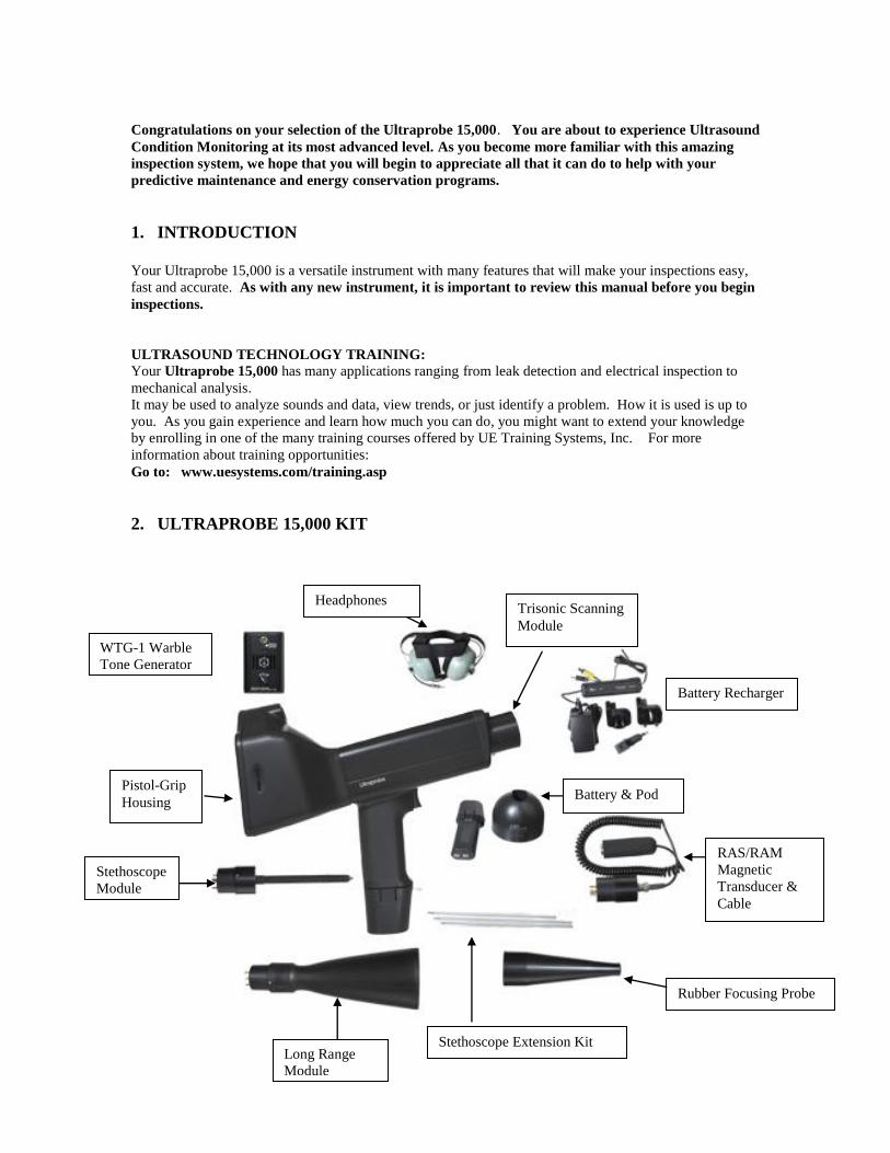
2. ULTRAPROBE 15,000 KIT
Pistol-Grip
Housing
WTG-1 Warble
Tone Generator
Rubber Focusing Probe
Long Range
Module
Stethoscope Extension Kit
Stethoscope
Module
Trisonic Scanning
Module
Battery & Pod
RAS/RAM
Magnetic
Transducer &
Cable
Headphones
Battery Recharger
6
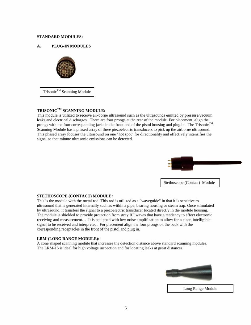
STANDARD MODULES:
A. PLUG-IN MODULES
TRISONICTM
SCANNING MODULE:
This module is utilized to receive air-borne ultrasound such as the ultrasounds emitted by pressure/vacuum
leaks and electrical discharges. There are four prongs at the rear of the module. For placement, align the
prongs with the four corresponding jacks in the front end of the pistol housing and plug in. The TrisonicTM
Scanning Module has a phased array of three piezoelectric transducers to pick up the airborne ultrasound.
This phased array focuses the ultrasound on one "hot spot" for directionality and effectively intensifies the
signal so that minute ultrasonic emissions can be detected.
STETHOSCOPE (CONTACT) MODULE: This is the module with the metal rod. This rod is utilized as a "waveguide" in that it is sensitive to
ultrasound that is generated internally such as within a pipe, bearing housing or steam trap. Once stimulated
by ultrasound, it transfers the signal to a piezoelectric transducer located directly in the module housing.
The module is shielded to provide protection from stray RF waves that have a tendency to effect electronic
receiving and measurement. . It is equipped with low noise amplification to allow for a clear, intelligible
signal to be received and interpreted. For placement align the four prongs on the back with the
corresponding receptacles in the front of the pistol and plug in.
LRM-(LONG RANGE MODULE):
A cone shaped scanning module that increases the detection distance above standard scanning modules.
The LRM-15 is ideal for high voltage inspection and for locating leaks at great distances.
Stethoscope (Contact) Module
TrisonicTM
Scanning Module
Long Range Module
7
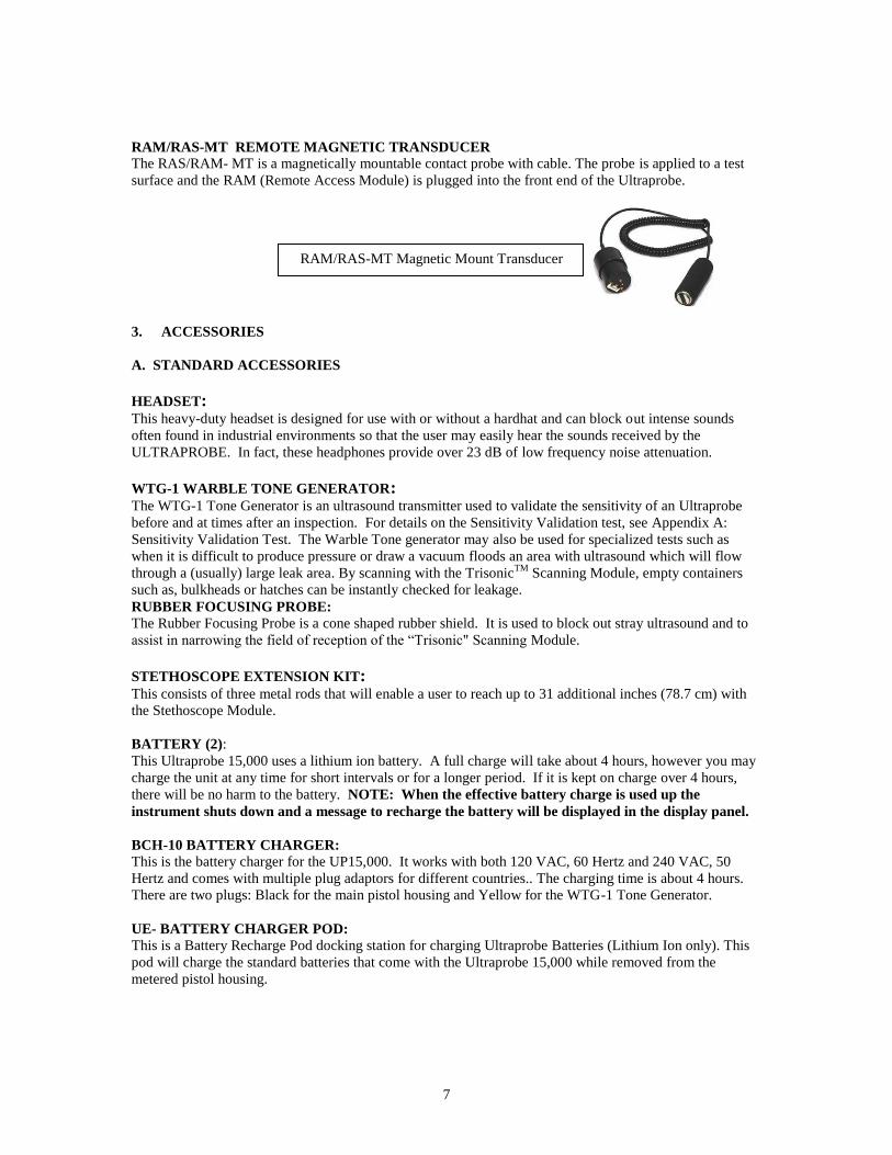
RAM/RAS-MT REMOTE MAGNETIC TRANSDUCER
The RAS/RAM- MT is a magnetically mountable contact probe with cable. The probe is applied to a test
surface and the RAM (Remote Access Module) is plugged into the front end of the Ultraprobe.
3. ACCESSORIES
A. STANDARD ACCESSORIES
HEADSET: This heavy-duty headset is designed for use with or without a hardhat and can block out intense sounds
often found in industrial environments so that the user may easily hear the sounds received by the
ULTRAPROBE. In fact, these headphones provide over 23 dB of low frequency noise attenuation.
WTG-1 WARBLE TONE GENERATOR: The WTG-1 Tone Generator is an ultrasound transmitter used to validate the sensitivity of an Ultraprobe
before and at times after an inspection. For details on the Sensitivity Validation test, see Appendix A:
Sensitivity Validation Test. The Warble Tone generator may also be used for specialized tests such as
when it is difficult to produce pressure or draw a vacuum floods an area with ultrasound which will flow
through a (usually) large leak area. By scanning with the TrisonicTM
Scanning Module, empty containers
such as, bulkheads or hatches can be instantly checked for leakage.
RUBBER FOCUSING PROBE:
The Rubber Focusing Probe is a cone shaped rubber shield. It is used to block out stray ultrasound and to
assist in narrowing the field of reception of the “Trisonic" Scanning Module.
STETHOSCOPE EXTENSION KIT: This consists of three metal rods that will enable a user to reach up to 31 additional inches (78.7 cm) with
the Stethoscope Module.
BATTERY (2):
This Ultraprobe 15,000 uses a lithium ion battery. A full charge will take about 4 hours, however you may
charge the unit at any time for short intervals or for a longer period. If it is kept on charge over 4 hours,
there will be no harm to the battery. NOTE: When the effective battery charge is used up the
instrument shuts down and a message to recharge the battery will be displayed in the display panel.
BCH-10 BATTERY CHARGER:
This is the battery charger for the UP15,000. It works with both 120 VAC, 60 Hertz and 240 VAC, 50
Hertz and comes with multiple plug adaptors for different countries.. The charging time is about 4 hours.
There are two plugs: Black for the main pistol housing and Yellow for the WTG-1 Tone Generator.
UE- BATTERY CHARGER POD:
This is a Battery Recharge Pod docking station for charging Ultraprobe Batteries (Lithium Ion only). This
pod will charge the standard batteries that come with the Ultraprobe 15,000 while removed from the
metered pistol housing.
RAM/RAS-MT Magnetic Mount Transducer
8
B. OPTIONAL ACCESSORIES
CFM-15:
A scanning module used for close proximity low level leak detection in pressure and vacuum systems.
UWC-15:
The UWC-15, Ultrasonic Waveform Concentrator, substantially increases the detection distance. The
UWC-15 is great for corona, tracking and arc detection at safe distances. Includes carrying case
DHC-2:
Headphone is for Standard Applications that do not require the use of a hard hat
TFSM: Telescoping Flexible Scanning Module: A flexible scanning probe that is bent to accommodate
odd scanning angles. The telescoping action helps scan hard to reach areas.
TFCM: Telescoping Stethoscope (Contact) Module: A contact probe for structure borne inspection that
can be extended for hard to reach areas.
UFMTG-1991:
The UFMTG 1991 is a multi-directional warble tone generator. It has a high power output with a circular
transmission pattern of 360.
WTG-2SP WARBLE PIPE THREADED TONE GENERATOR: A Warble Tone Generator that is used in test conditions where it is not possible to physically place the
standard WTG-1 Warble Tone Generator, such as in pipes or in certain heat exchangers or tanks. Features:
1” NPT male threaded nipple with adapters for ¾” and ½” female nipple with a 10 turn amplitude
adjustment dial. Metric adapters are also available.
BCH-WTG: Optional 220 VAC @ 50 Hz charger for all Warble Tone Generators. The line input is 220 VAC @ 50Hz
and the charging time is about 8 hours.
HTS-15:
Holster set for the UP15,000.
9
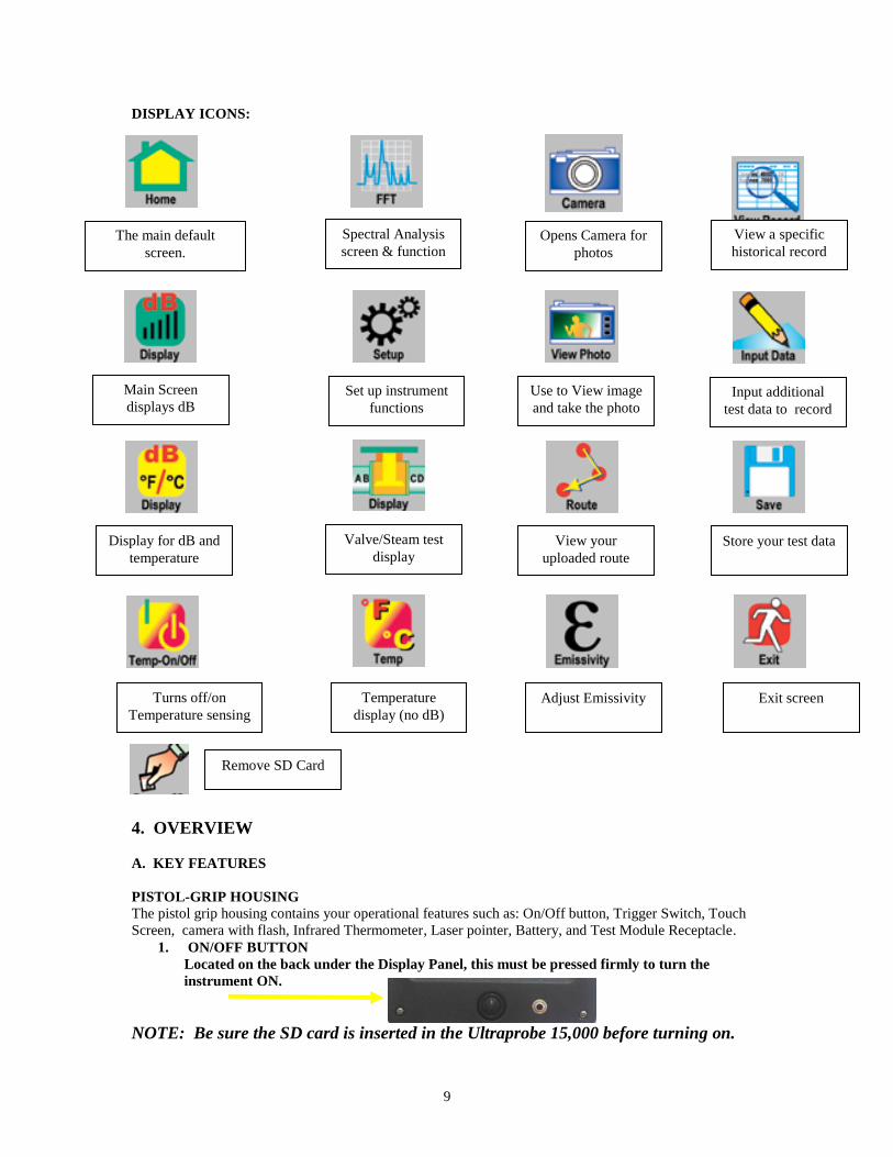
DISPLAY ICONS:
\
4. OVERVIEW
A. KEY FEATURES
PISTOL-GRIP HOUSING
The pistol grip housing contains your operational features such as: On/Off button, Trigger Switch, Touch
Screen, camera with flash, Infrared Thermometer, Laser pointer, Battery, and Test Module Receptacle.
1. ON/OFF BUTTON
Located on the back under the Display Panel, this must be pressed firmly to turn the
instrument ON.
NOTE: Be sure the SD card is inserted in the Ultraprobe 15,000 before turning on.
The main default
screen.
Spectral Analysis
screen & function Opens Camera for
photos
View a specific
historical record
Main Screen
displays dB Set up instrument
functions
Use to View image
and take the photo Input additional
test data to record
Display for dB and
temperature
Valve/Steam test
display View your
uploaded route
Store your test data
Temperature
display (no dB)
Turns off/on
Temperature sensing
Adjust Emissivity Exit screen
Remove SD Card
10
a. TURN OFF:
1. Press the On/Off button
2. Touch the Off Box on the display screen
b. SUSPEND: In place of turning the instrument on and off in between short intervals of use, or
to extend the use time on a battery (normally 4 hours of continuous use after a complete charge),
put the instrument on SUSPEND. To do this:
1. Press the On/Off button
2. Touch the SUSPEND box on the display screen.
c. RETURN TO OPERATION MODE (cancel the SUSPEND mode) :
1. Touch the display screen and display will re-open.
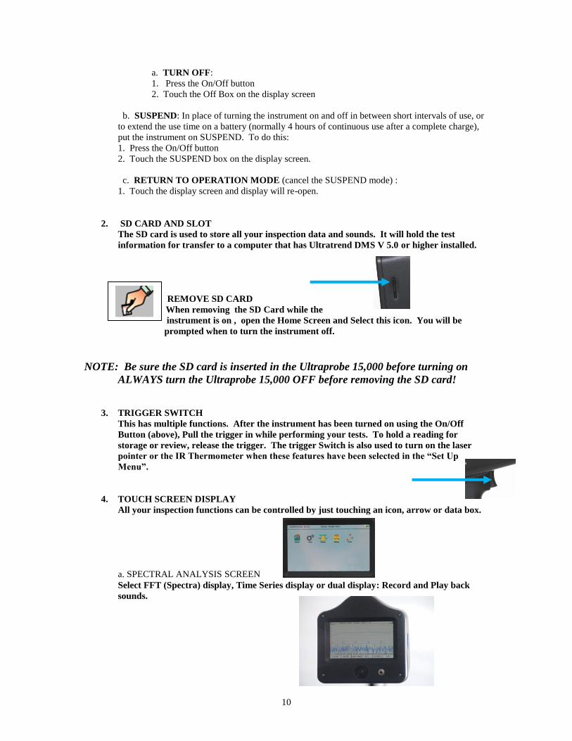
2. SD CARD AND SLOT
The SD card is used to store all your inspection data and sounds. It will hold the test
information for transfer to a computer that has Ultratrend DMS V 5.0 or higher installed.
REMOVE SD CARD
When removing the SD Card while the
instrument is on , open the Home Screen and Select this icon. You will be
prompted when to turn the instrument off.
NOTE: Be sure the SD card is inserted in the Ultraprobe 15,000 before turning on
ALWAYS turn the Ultraprobe 15,000 OFF before removing the SD card!
3. TRIGGER SWITCH
This has multiple functions. After the instrument has been turned on using the On/Off
Button (above), Pull the trigger in while performing your tests. To hold a reading for
storage or review, release the trigger. The trigger Switch is also used to turn on the laser
pointer or the IR Thermometer when these features have been selected in the “Set Up
Menu”.
4. TOUCH SCREEN DISPLAY
All your inspection functions can be controlled by just touching an icon, arrow or data box.
a. SPECTRAL ANALYSIS SCREEN
Select FFT (Spectra) display, Time Series display or dual display: Record and Play back
sounds.
11
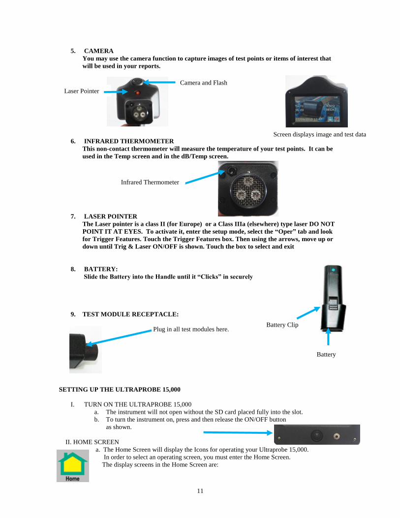
5. CAMERA
You may use the camera function to capture images of test points or items of interest that
will be used in your reports.
6. INFRARED THERMOMETER
This non-contact thermometer will measure the temperature of your test points. It can be
used in the Temp screen and in the dB/Temp screen.
7. LASER POINTER
The Laser pointer is a class II (for Europe) or a Class IIIa (elsewhere) type laser DO NOT
POINT IT AT EYES. To activate it, enter the setup mode, select the “Oper” tab and look
for Trigger Features. Touch the Trigger Features box. Then using the arrows, move up or
down until Trig & Laser ON/OFF is shown. Touch the box to select and exit
8. BATTERY:
Slide the Battery into the Handle until it “Clicks” in securely
9. TEST MODULE RECEPTACLE:
Plug in all test modules here.
SETTING UP THE ULTRAPROBE 15,000
I. TURN ON THE ULTRAPROBE 15,000
a. The instrument will not open without the SD card placed fully into the slot.
b. To turn the instrument on, press and then release the ON/OFF button
as shown.
II. HOME SCREEN
a. The Home Screen will display the Icons for operating your Ultraprobe 15,000.
In order to select an operating screen, you must enter the Home Screen.
The display screens in the Home Screen are:
Battery
Battery Clip
Camera and Flash
Laser Pointer
Infrared Thermometer
Screen displays image and test data
12
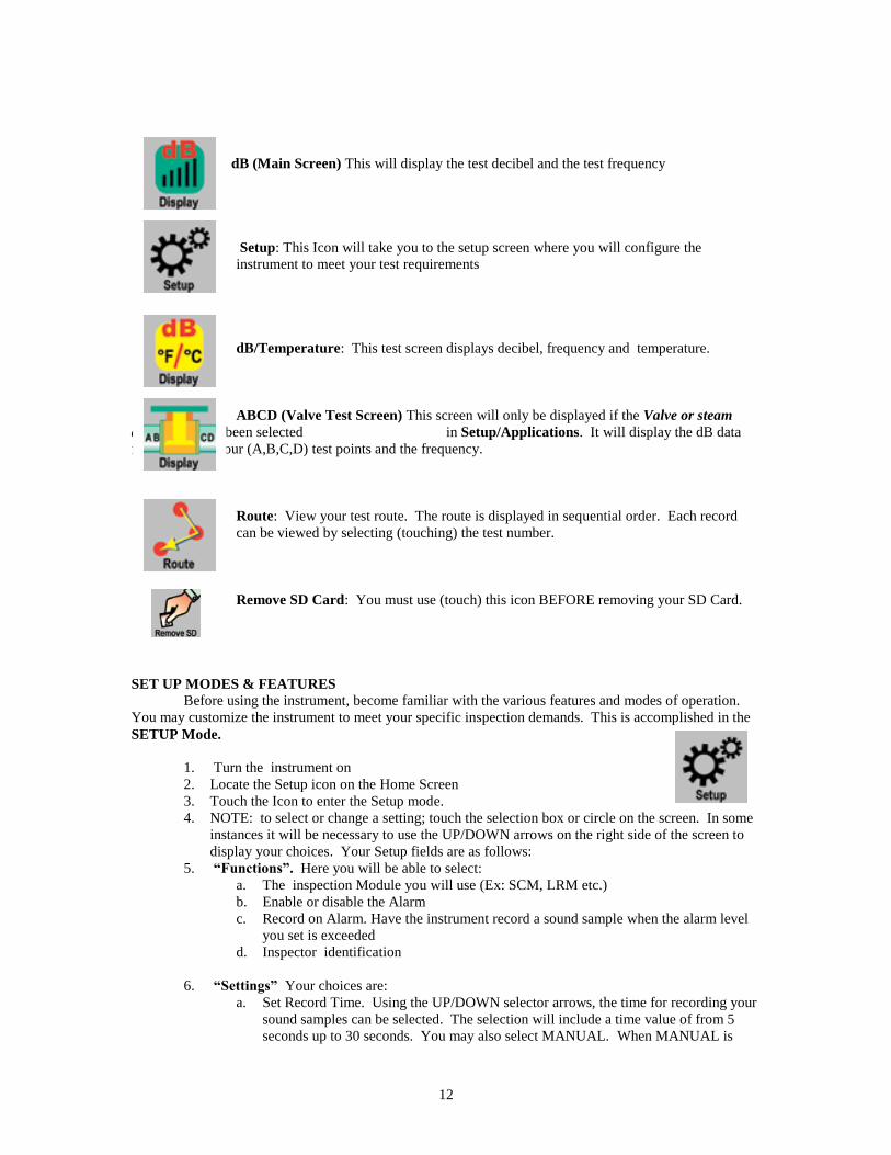
dB (Main Screen) This will display the test decibel and the test frequency
Setup: This Icon will take you to the setup screen where you will configure the
instrument to meet your test requirements
dB/Temperature: This test screen displays decibel, frequency and temperature.
ABCD (Valve Test Screen) This screen will only be displayed if the Valve or steam
application has been selected in Setup/Applications. It will display the dB data
for each of the four (A,B,C,D) test points and the frequency.
Route: View your test route. The route is displayed in sequential order. Each record
can be viewed by selecting (touching) the test number.
Remove SD Card: You must use (touch) this icon BEFORE removing your SD Card.
SET UP MODES & FEATURES
Before using the instrument, become familiar with the various features and modes of operation.
You may customize the instrument to meet your specific inspection demands. This is accomplished in the
SETUP Mode.
1. Turn the instrument on
2. Locate the Setup icon on the Home Screen
3. Touch the Icon to enter the Setup mode.
4. NOTE: to select or change a setting; touch the selection box or circle on the screen. In some
instances it will be necessary to use the UP/DOWN arrows on the right side of the screen to
display your choices. Your Setup fields are as follows:
5. “Functions”. Here you will be able to select:
a. The inspection Module you will use (Ex: SCM, LRM etc.)
b. Enable or disable the Alarm
c. Record on Alarm. Have the instrument record a sound sample when the alarm level
you set is exceeded
d. Inspector identification
6. “Settings” Your choices are:
a. Set Record Time. Using the UP/DOWN selector arrows, the time for recording your
sound samples can be selected. The selection will include a time value of from 5
seconds up to 30 seconds. You may also select MANUAL. When MANUAL is
13
selected, press the REC (recording) box in the Spectral Screen. To stop recording,
Press STOP.
b. Default Settings. When Yes is selected the instrument settings will change to the
original settings as it came from the factory.
c. Sensitivity Default: the user can select a sensitivity value so that every time the
instrument is turned on for testing, that value will be the starting “high” level. For
example, the default factory Sensitivity value is 70. In some routes this will be too
high and to save time the inspector will set to a lower value for a starting point on
that route.
d. Frequency Default: The default frequency from the factory is 40 kHz. If the
Ultraprobe is to be used consistently at another frequency, set the default to that
frequency. Every time the instrument is turned on, it will default to that selected
frequency. For example, if most of the inspections are to be mechanical, the user
might set the default frequency to 30 kHz.
e. Turn off time: The Turn-off time can be set to 5, 10 or 15 minutes. Or it can be
disabled. In disable, when the instrument is turned on, it will stay on until either it is
turned off, set in suspend or the battery charge is depleted.
f. WAV Sample Rate. When recording a sound for playback in the Spectral analysis
screen or in UE Spectralyzer, the operator can adjust the sample rate. The default
sample rate is 16,000.
g. Instrument Setup: The factory default is Manual. All adjustments are made by the
inspector as he/she goes through the route. The Automatic setting is used after the
initial baseline data has been uploaded to the Ultraprobe 15,000. In the Automatic
setting the instrument will move sequentially from one test point to the next, and set
itself for the original baseline setup, which will include the Frequency and
Sensitivity for that point. For example, if the operator is testing bearings, the
instrument will move from test point 1 to test point two and the if the baseline data
was set at a sensitivity level of 43 with a frequency of 30 kHz, the instrument will
automatically set for these parameters.
7. Oper (Operation) The choices for this feature are:
a. Display Response: This affects the movement of the intensity indicator. It may be
set for Slow, Medium or Fast.
b. Headphone Volume: There may be situations in which the sound level in the
headphones is uncomfortably high and the sensitivity level must remain in a high
level. To make this comfortable for the user, the volume of the headphones can be
adjusted for 100% of volume to as low as 0% of volume.
c. Trigger Features: The trigger is used to actively display a dB reading while pulled
and freeze a dB reading when released. While the trigger is pulled the operator has
the choice of: Trigger and Laser ON/OFF or Trigger ON, Laser always OFF. If
Trigger and Laser On/Off is selected, every time the trigger is pulled, the Laser will
be ON. When the Trigger is released, the Laser will turn OFF. If Trigger ON, Laser
always OFF is selected, the Laser will always be off, even when the Trigger is pulled
on for testing.
d. Frequency Adjust: An inspector might want to be sure the frequency is not changed
during a route. To lock the frequency, select No, to enable frequency tuning, select
Yes.
8. Additional: Selections here are:
a. Upgrade program: Whenever there is an upgrade to the Ultraprobe 15,000 it may be
downloaded off the web onto the SD card. Insert the SD card with the upgrade and
use Upgrade Program.
b. Restore List: All test information is set as a list in Ultratrend DMS, the standard
operating software that accompanies the Ultraprobe. If list identification letters have
been changed in Ultratrend DMS, they will be entered into the Ultraprobe. Restore
lists will reset the Ultraprobe back to the original lists as set at the factory.
c. Units: Set measuring units for Standard or Metric.
14
d. Cal Due Date: This is set at the factory and reset every time the Ultraprobe is sent
back after calibration.
e. Set Time and Date: Set the time and date as appropriate for a specific area in which
the instrument is used.
9. Apps (Applications): Each application has unique data. When an application is selected the
instrument will automatically set up specific fields that are unique to that application. The
specific applications are:
a. Generic
b. Valves
c. Bearing
d. Electrical
e. Steam
f. Leak
There is one other selection on the Apps page: Fields
g. Fields: These are test information fields that can accompany test results. Select the
specific fields for an application and then touch OK to set. While performing tests
on a route after exiting setup, the operator can select the Input Data Icon to select any
of the following (if they have been selected).
i. Test Results
ii. Temperature
iii. Application
iv. Pressure
v. Pipe Diameter
vi. Type
VIEWING AND SELECTING ICONS
1. Icons may be viewed on any of the following display screens: Main, dB and
Temperature, Valve and Temperature.
2. Only two icons at a time may be shown continuously
3. To view icons: touch the bottom of the screen.
4. To view more icons, use the “left/right” arrows to move the icons on and off the screen
5. To select an icon for continuous display and easy access on the screen:
a. Touch the bottom of the screen to display the icons
b. Use the left/right arrows until the icon you will use is displayed
c. Touch the icon and slide it up to the middle of the left side of the display screen
USING SCREENS:
To use any of the screens:
a. Turn on the Ultraprobe by pressing the ON button
b. When the Home screen opens, select an Icon
c. To use an operational screen such as “Main”, “dB/Temp”,
“Temp”, or Valve, pull the trigger in and begin your
inspection. If no or very little ultrasound is present of if the
sensitivity value is too high for the test area, the dB will not
show on the screen. 3 Dashed (---) lines will show. Adjust the
“S” (Sensitivity value) by touching the Sensitivity box and then
use the Up/DOWN arrows to move the S value up or down as
needed.
d. To freeze a reading for saving or observation, release the
trigger.
15
Sensitivity value
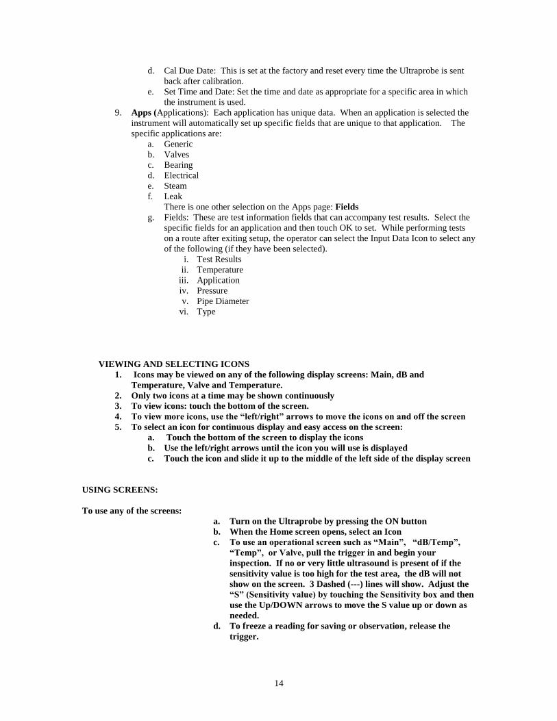
1. Home: When the Ultraprobe is turned on, the Home screen will be displayed. There are 4
icons shown: Main screen, Setup, dB and Temperature Screen, and Route. Should the Valve
or Steam application be selected, the Valve icon (ABCD) will also be shown. Select one of
the icons to enter and use the full features of the Ultraprobe 15,000.
NOTE: To change from one operating screen (such as Main, dB/Temp or Valve) to another,
you must return to the Home screen.
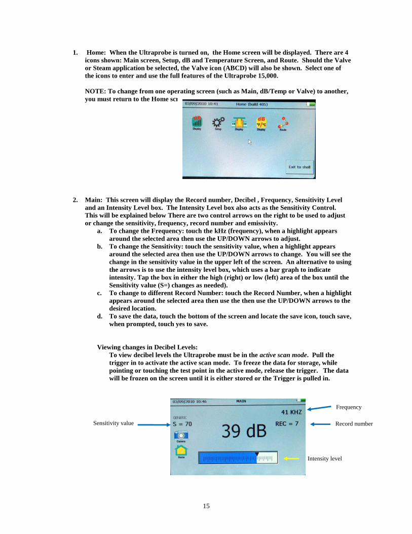
2. Main: This screen will display the Record number, Decibel , Frequency, Sensitivity Level
and an Intensity Level box. The Intensity Level box also acts as the Sensitivity Control.
This will be explained below There are two control arrows on the right to be used to adjust
or change the sensitivity, frequency, record number and emissivity.
a. To change the Frequency: touch the kHz (frequency), when a highlight appears
around the selected area then use the UP/DOWN arrows to adjust.
b. To change the Sensitivity: touch the sensitivity value, when a highlight appears
around the selected area then use the UP/DOWN arrows to change. You will see the
change in the sensitivity value in the upper left of the screen. An alternative to using
the arrows is to use the intensity level box, which uses a bar graph to indicate
intensity. Tap the box in either the high (right) or low (left) area of the box until the
Sensitivity value (S=) changes as needed).
c. To change to different Record Number: touch the Record Number, when a highlight
appears around the selected area then use the then use the UP/DOWN arrows to the
desired location.
d. To save the data, touch the bottom of the screen and locate the save icon, touch save,
when prompted, touch yes to save.
Viewing changes in Decibel Levels:
To view decibel levels the Ultraprobe must be in the active scan mode. Pull the
trigger in to activate the active scan mode. To freeze the data for storage, while
pointing or touching the test point in the active mode, release the trigger. The data
will be frozen on the screen until it is either stored or the Trigger is pulled in.
Frequency
Intensity level
Record number
16
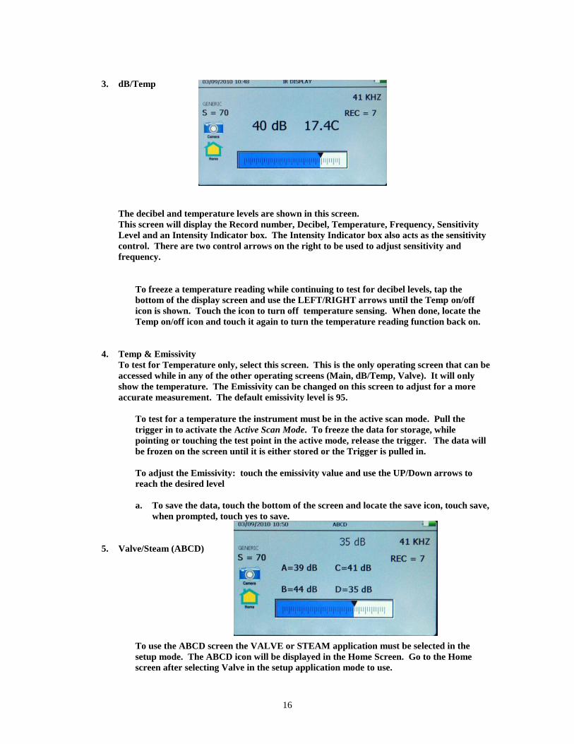
3. dB/Temp
The decibel and temperature levels are shown in this screen.
This screen will display the Record number, Decibel, Temperature, Frequency, Sensitivity
Level and an Intensity Indicator box. The Intensity Indicator box also acts as the sensitivity
control. There are two control arrows on the right to be used to adjust sensitivity and
frequency.
To freeze a temperature reading while continuing to test for decibel levels, tap the
bottom of the display screen and use the LEFT/RIGHT arrows until the Temp on/off
icon is shown. Touch the icon to turn off temperature sensing. When done, locate the
Temp on/off icon and touch it again to turn the temperature reading function back on.
4. Temp & Emissivity
To test for Temperature only, select this screen. This is the only operating screen that can be
accessed while in any of the other operating screens (Main, dB/Temp, Valve). It will only
show the temperature. The Emissivity can be changed on this screen to adjust for a more
accurate measurement. The default emissivity level is 95.
To test for a temperature the instrument must be in the active scan mode. Pull the
trigger in to activate the Active Scan Mode. To freeze the data for storage, while
pointing or touching the test point in the active mode, release the trigger. The data will
be frozen on the screen until it is either stored or the Trigger is pulled in.
To adjust the Emissivity: touch the emissivity value and use the UP/Down arrows to
reach the desired level
a. To save the data, touch the bottom of the screen and locate the save icon, touch save,
when prompted, touch yes to save.
5. Valve/Steam (ABCD)
To use the ABCD screen the VALVE or STEAM application must be selected in the
setup mode. The ABCD icon will be displayed in the Home Screen. Go to the Home
screen after selecting Valve in the setup application mode to use.
17
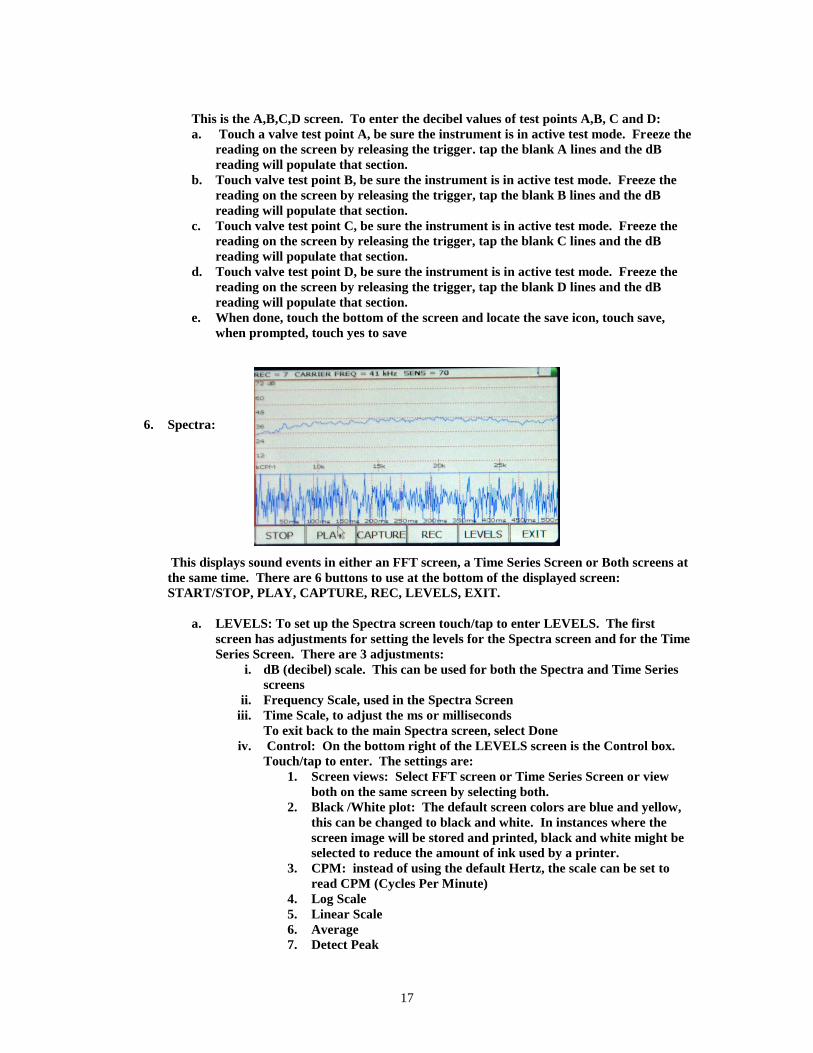
This is the A,B,C,D screen. To enter the decibel values of test points A,B, C and D:
a. Touch a valve test point A, be sure the instrument is in active test mode. Freeze the
reading on the screen by releasing the trigger. tap the blank A lines and the dB
reading will populate that section.
b. Touch valve test point B, be sure the instrument is in active test mode. Freeze the
reading on the screen by releasing the trigger, tap the blank B lines and the dB
reading will populate that section.
c. Touch valve test point C, be sure the instrument is in active test mode. Freeze the
reading on the screen by releasing the trigger, tap the blank C lines and the dB
reading will populate that section.
d. Touch valve test point D, be sure the instrument is in active test mode. Freeze the
reading on the screen by releasing the trigger, tap the blank D lines and the dB
reading will populate that section.
e. When done, touch the bottom of the screen and locate the save icon, touch save,
when prompted, touch yes to save
6. Spectra:
This displays sound events in either an FFT screen, a Time Series Screen or Both screens at
the same time. There are 6 buttons to use at the bottom of the displayed screen:
START/STOP, PLAY, CAPTURE, REC, LEVELS, EXIT.
a. LEVELS: To set up the Spectra screen touch/tap to enter LEVELS. The first
screen has adjustments for setting the levels for the Spectra screen and for the Time
Series Screen. There are 3 adjustments:
i. dB (decibel) scale. This can be used for both the Spectra and Time Series
screens
ii. Frequency Scale, used in the Spectra Screen
iii. Time Scale, to adjust the ms or milliseconds
To exit back to the main Spectra screen, select Done
iv. Control: On the bottom right of the LEVELS screen is the Control box.
Touch/tap to enter. The settings are:
1. Screen views: Select FFT screen or Time Series Screen or view
both on the same screen by selecting both.
2. Black /White plot: The default screen colors are blue and yellow,
this can be changed to black and white. In instances where the
screen image will be stored and printed, black and white might be
selected to reduce the amount of ink used by a printer.
3. CPM: instead of using the default Hertz, the scale can be set to
read CPM (Cycles Per Minute)
4. Log Scale
5. Linear Scale
6. Average
7. Detect Peak
18
8. Exit on Save Wave: After a sound sample has been recorded and
saved, the Instrument will exit and return to the previously selected
Operating Screens.
b. When through adjusting the settings or to exit back to the Spectra Screen, select
DONE
c. STOP/START: When the Spectra screen opens it will start to display sounds sensed
by the Ultraprobe, to stop this, touch/tap STOP, to start testing a sound sample,
touch/tap START
d. PLAY: To play a recorded sound back on the Ultraprobe and to view it while
hearing it, touch/tap PLAY.
e. CAPTURE: To capture the image of the screen, touch/tap CAPTURE. This image
can be used in reports.
f. REC ( Record), press this to record a sound sample. If in the MANUAL record
mode, press the REC button. To stop in the Manual mode, press STOP. If the
instrument has been set for a recording time in the Setup Mode, then just touch/tap
and release the REC box.
g. EXIT: exit to a previously selected screen.
7. SELECTING ICONS FOR DISPLAY SCREEN
NOTE: Only two icons at a time can be permanently displayed on an operational screen.
a. Touch the bottom of an operational screen (Main, dB/Temp, Temp, Valve)
b. Icons will appear
c. Touch and drag the desired icon to the center of the left side of the screen
8. STORING A RECORD
a. Release the trigger to freeze the desired reading
b. Locate the Store Record icon
c. Touch/tap the Store icon.
9. RECORDING A SOUND
a. Locate and touch the Spectra (FFT) icon
b. Touch/tap REC (Record)
c. If the timed recording has been selected in the Settings/Set Record Time, the
recording process will stop at the selected time
d. If the Settings/Set Recording Time is in the Manual mode, to stop recording,
touch/tap STOP.
e. You will be asked: Save WAV File, Yes or No. To save, touch/tap Yes.
f. To activate the Spectra screen when not in the REC Mode, touch/tap START to run
the spectra (if STOP is shown the spectra screen is operating. To stop the spectra
screen from running, touch/tap the STOP button). Every time the START button is
tapped to run the spectra screen, you will be observing an averaging of the spectra
on the screen. When it is stopped and restarted, the averaging process begins again.
19
10. CAPTURING THE SPECTRA SCREEN IMAGE
The Image of the selected spectra screen can be saved for viewing or entering in a report. To
capture the screen image:
a. Check the top left of the spectra screen to be sure you are at the desired Record
number.
b. Touch the CAPTURE tab
c. Select Yes to save.
11. ENTERING TEST DATA
a. Locate the Input Data icon
b. The Test data information will vary with each application. The title of the
information will be shown in the upper left part of the screen
c. To move from one selection to another, use the Left/Right arrows
d. Touch/tap the screen of the desired data (ex: RPM or TEMP)
e. Use the UP/DOWN arrows to enter the desired data
f. These input data fields are set (and may be changed) in Ultratrend DMS,
12. VIEW RECORD
a. A record can be viewed in an operational screen. If the record number displayed is
not the record you want to read:
b. Touch/tap the Record box
c. Use the UP/DOWN arrows to locate the desired record number
d. Locate the View Record icon
e. Touch/tap the icon
f. When the data appears, you can scroll for all the stored data, touch the screen and
drag your finger up or down.
13. VIEWING A ROUTE
a. Locate the Route icon by tapping the bottom of the display screen
b. Touch/tap the Route icon
c. Sorting Route Criteria: Using the SORT button, every time it is pressed it will
rotate the sort. Sort options are: Record #, Low Status, High Status, OK Status or
Not Updated.
d. Reviewing a Photo: If a Y is shown in the P (Photo) column you may view the image
by touching/tapping the Y. If multiple images are stored, view each by
touching/tapping the display screen until you have viewed all images.
e. Reviewing Wave Files: If a wave file is stored you may play either the baseline or
current wave file. To play the baseline, touch/tap the Y in the W column and play.
f. To open the record in the main dB display, touch/tap the Record #.
20
14. Camera: To take a picture of a test point, touch the Camera icon. The Camera screen will
show:
a. Flash: On/Off: If you want the flash to be on, press ON, if you do not want the
flash, press OFF.
b. Zoom: If you want to zoom in or out ( up to 3X), tap the zoom box at the desired
zoom location. The zoom level will be displayed to the left of the zoom box.
c. To capture the image:
i. Touch the View Photo icon and the image will be shown on the screen.
ii. Touch the image screen to capture the image.
iii. The image will appear with the test data.
iv. To save, press Save. You will be asked to confirm if you want to save the
picture. IF you wish to save the picture, touch Yes. If you do not want to
save the image at this point, press No. If you do not want to save the
picture after you view it then press the Exit icon.
TRIGGER SWITCH:
The Trigger Switch is used to display the active dB reading. To observe the active dB reading, pull the
trigger and hold it. For example, when scanning a leak or electric emission, pull the trigger in and scan the
test area until you want to freeze the reading for storage or review. At that moment, release the trigger. To
store the dB you have frozen on the screen, select the Save icon.
The trigger can also be used to turn on the Laser Pointer. Note that the Laser Pointer will work only if it
has been set to ON in the setup menu.
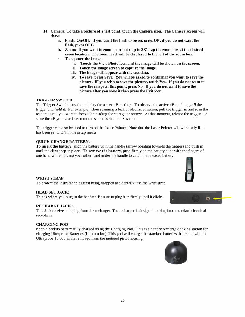
QUICK CHANGE BATTERY:
To insert the battery, align the battery with the handle (arrow pointing towards the trigger) and push in
until the clips snap in place. To remove the battery, push firmly on the battery clips with the fingers of
one hand while holding your other hand under the handle to catch the released battery.
WRIST STRAP:
To protect the instrument, against being dropped accidentally, use the wrist strap.
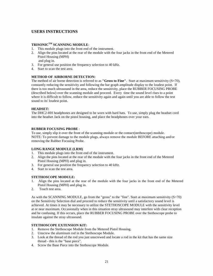
HEAD SET JACK:
This is where you plug in the headset. Be sure to plug it in firmly until it clicks.
RECHARGE JACK :
This Jack receives the plug from the recharger. The recharger is designed to plug into a standard electrical
receptacle.
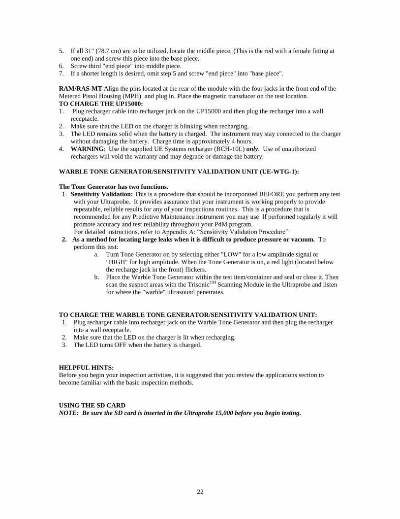
CHARGING POD Keep a backup battery fully charged using the Charging Pod. This is a battery recharge docking station for
charging Ultraprobe Batteries (Lithium Ion). This pod will charge the standard batteries that come with the
Ultraprobe 15,000 while removed from the metered pistol housing.
21
USERS INSTRUCTIONS
TRISONICTM
SCANNING MODULE:
1. This module plugs into the front end of the instrument.
2. Align the pins located at the rear of the module with the four jacks in the front end of the Metered
Pistol Housing (MPH)
and plug in.
3. For general use position the frequency selection to 40 kHz.
4. Start to scan the test area.
METHOD OF AIRBORNE DETECTION:
The method of air borne detection is referred to as "Gross to Fine". Start at maximum sensitivity (S=70),
constantly reducing the sensitivity and following the bar graph amplitude display to the loudest point. If
there is too much ultrasound in the area, reduce the sensitivity, place the RUBBER FOCUSING PROBE
(described below) over the scanning module and proceed. Every time the sound level rises to a point
where it is difficult to follow, reduce the sensitivity again and again until you are able to follow the test
sound to its' loudest point.
HEADSET:
The DHC2-HH headphones are designed to be worn with hard hats. To use, simply plug the headset cord
into the headset Jack on the pistol housing, and place the headphones over your ears.
RUBBER FOCUSING PROBE :
To use, simply slip it over the front of the scanning module or the contact(stethoscope) module.
NOTE: To prevent damage to the module plugs, always remove the module BEFORE attaching and/or
removing the Rubber Focusing Probe.
LONG RANGE MODULE (LRM)
1. This module plugs into the front end of the instrument.
2. Align the pins located at the rear of the module with the four jacks in the front end of the Metered
Pistol Housing (MPH) and plug in.
3. For general use position the frequency selection to 40 kHz.
4. Start to scan the test area.
STETHOSCOPE MODULE:
1. Align the pins located at the rear of the module with the four jacks in the front end of the Metered
Pistol Housing (MPH) and plug in.
2. Touch test area.
As with the SCANNING MODULE, go from the "gross" to the "fine". Start at maximum sensitivity (S=70)
on the Sensitivity Selection dial and proceed to reduce the sensitivity until a satisfactory sound level is
achieved. At times it may be necessary to utilize the STETHOSCOPE MODULE with the sensitivity level
at or near maximum. Occasionally when in this situation stray ultrasound may interfere with clear reception
and be confusing. If this occurs, place the RUBBER FOCUSING PROBE over the Stethoscope probe to
insulate against the stray ultrasound.
STETHOSCOPE EXTENSION KIT: 1. Remove the Stethoscope Module from the Metered Pistol Housing.
2. Unscrew the aluminum rod in the Stethoscope Module.
3. Look at the thread of the rod you just unscrewed and locate a rod in the kit that has the same size
thread - this is the "base piece".
4. Screw the Base Piece into the Stethoscope Module.
22
5. If all 31" (78.7 cm) are to be utilized, locate the middle piece. (This is the rod with a female fitting at
one end) and screw this piece into the base piece.
6. Screw third "end piece" into middle piece.
7. If a shorter length is desired, omit step 5 and screw "end piece" into "base piece".
RAM/RAS-MT Align the pins located at the rear of the module with the four jacks in the front end of the
Metered Pistol Housing (MPH) and plug in. Place the magnetic transducer on the test location.
TO CHARGE THE UP15000: 1. Plug recharger cable into recharger jack on the UP15000 and then plug the recharger into a wall
receptacle.
2. Make sure that the LED on the charger is blinking when recharging.
3. The LED remains solid when the battery is charged. The instrument may stay connected to the charger
without damaging the battery. Charge time is approximately 4 hours.
4. WARNING: Use the supplied UE Systems recharger (BCH-10L) only. Use of unauthorized
rechargers will void the warranty and may degrade or damage the battery.
WARBLE TONE GENERATOR/SENSITIVITY VALIDATION UNIT (UE-WTG-1):
The Tone Generator has two functions.
1. Sensitivity Validation: This is a procedure that should be incorporated BEFORE you perform any test
with your Ultraprobe. It provides assurance that your instrument is working properly to provide
repeatable, reliable results for any of your inspections routines. This is a procedure that is
recommended for any Predictive Maintenance instrument you may use If performed regularly it will
promote accuracy and test reliability throughout your PdM program.
For detailed instructions, refer to Appendix A: “Sensitivity Validation Procedure”
2. As a method for locating large leaks when it is difficult to produce pressure or vacuum. To
perform this test:
a. Turn Tone Generator on by selecting either "LOW" for a low amplitude signal or
"HIGH" for high amplitude. When the Tone Generator is on, a red light (located below
the recharge jack in the front) flickers.
b. Place the Warble Tone Generator within the test item/container and seal or close it. Then
scan the suspect areas with the TrisonicTM
Scanning Module in the Ultraprobe and listen
for where the "warble" ultrasound penetrates.
TO CHARGE THE WARBLE TONE GENERATOR/SENSITIVITY VALIDATION UNIT: 1. Plug recharger cable into recharger jack on the Warble Tone Generator and then plug the recharger
into a wall receptacle.
2. Make sure that the LED on the charger is lit when recharging.
3. The LED turns OFF when the battery is charged.
HELPFUL HINTS:
Before you begin your inspection activities, it is suggested that you review the applications section to
become familiar with the basic inspection methods.
USING THE SD CARD
NOTE: Be sure the SD card is inserted in the Ultraprobe 15,000 before you begin testing.
23
PLAYING RECORDED SOUNDS:
You may review baseline sounds that have been uploaded to your Ultraprobe and compare them to
currently recorded sounds.
1. Open Routes and select the record with the baseline sound. If the baseline sound has been
uploaded it will be noted with a “Y” in the Wave (“W”) column.
2. Touch the “Y” and the Spectra screen will open and begin to play the sound.
a. To compare with a recently recorded sound for the selected route number:
1. Exit the Spectra Screen, open an operating screen ( Main or Temp/dB),
2. Make sure the screen displays the appropriate record number in your route
3. Re-open Spectra
4. Select PLAY
5. A window will open displaying two wave files: one with a prefix of BL is the Baseline wav
file the other with a prefix of SA is the current wav file
6. Touch the Next button to move to the wav file you want to play
7. To play, touch the Select button
AUTO-SHUTDOWN BATTERY FEATURE
The Ultraprobe 15,000 is equipped with an auto-shutdown feature when the battery energy is depleted. A
message in the Display Panel will read “RECHARGE BATTERY”, and the instrument will go into a
“sleep” mode. The instrument will automatically store all records onto the SD card at shutdown.
After the battery is replaced with a freshly charged battery, turn the Ultraprobe 15,000 back on and
continue your testing
.
RESETTING THE ON BOARD COMPUTER:
There is no reset switch on the instrument. Should it be necessary to reset the instrument:, Enter SETUP
Mode touch/tap the tab “OPERATIONS” , touch/tap DEFAULT SETTINGS) and choose the YES.
WARNING: Selecting Default Settings erases all records stored in the instrument. If that does not work, disconnect the battery for one (1) minute and then reconnect the battery.
ALARM ENABLE/DISABLE
To enable or disable an alarm level: (the alarm levels are set in Ultratrend DMS and sent to the instrument.
1. Enter Setup , Functions
2. Select Alarm Enable or Disable.
3. When Alarm level is exceeded the display will change color and, if selected the sound will be
recorded.
24
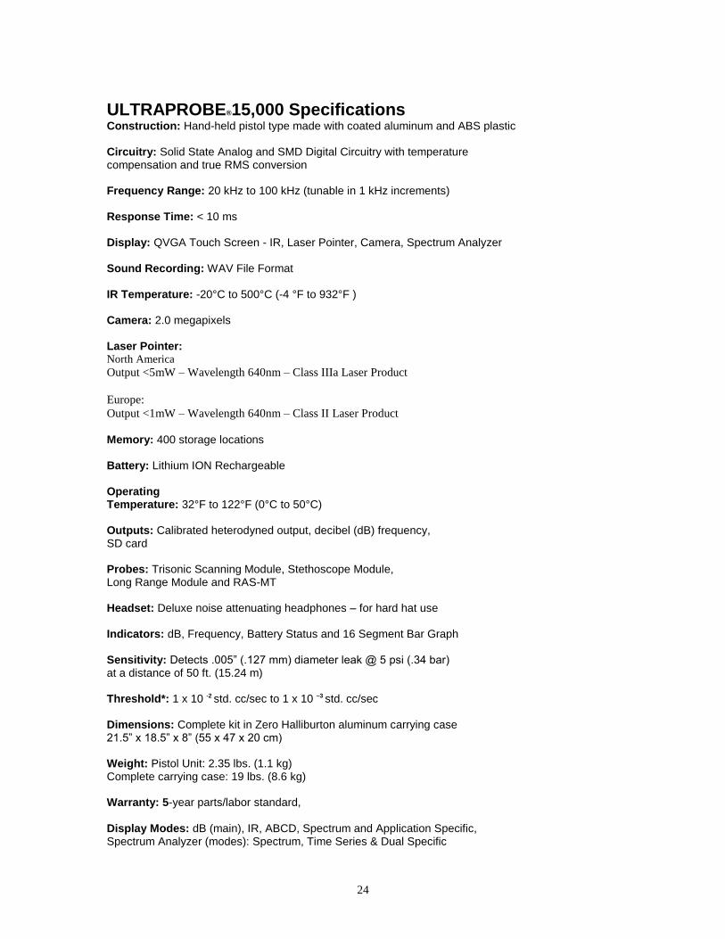
ULTRAPROBE®15,000 Specifications Construction: Hand-held pistol type made with coated aluminum and ABS plastic Circuitry: Solid State Analog and SMD Digital Circuitry with temperature compensation and true RMS conversion Frequency Range: 20 kHz to 100 kHz (tunable in 1 kHz increments) Response Time: < 10 ms Display: QVGA Touch Screen - IR, Laser Pointer, Camera, Spectrum Analyzer Sound Recording: WAV File Format IR Temperature: -20°C to 500°C (-4 °F to 932°F ) Camera: 2.0 megapixels Laser Pointer: North America Output <5mW – Wavelength 640nm – Class IIIa Laser Product
Europe:
Output <1mW – Wavelength 640nm – Class II Laser Product
Memory: 400 storage locations Battery: Lithium ION Rechargeable Operating Temperature: 32°F to 122°F (0°C to 50°C) Outputs: Calibrated heterodyned output, decibel (dB) frequency, SD card Probes: Trisonic Scanning Module, Stethoscope Module, Long Range Module and RAS-MT Headset: Deluxe noise attenuating headphones – for hard hat use Indicators: dB, Frequency, Battery Status and 16 Segment Bar Graph Sensitivity: Detects .005” (.127 mm) diameter leak @ 5 psi (.34 bar) at a distance of 50 ft. (15.24 m) Threshold*: 1 x 10 -2
std. cc/sec to 1 x 10 –3 std. cc/sec
Dimensions: Complete kit in Zero Halliburton aluminum carrying case 21.5” x 18.5” x 8” (55 x 47 x 20 cm) Weight: Pistol Unit: 2.35 lbs. (1.1 kg) Complete carrying case: 19 lbs. (8.6 kg) Warranty: 5-year parts/labor standard,
Display Modes: dB (main), IR, ABCD, Spectrum and Application Specific, Spectrum Analyzer (modes): Spectrum, Time Series & Dual Specific
25
*depends on leak configuration Ultraprobe 15,000 Kit: Meets and exceeds ASTM E1002-2005 requirements for Leak Detection. Covered by one or more of the following patents: 0151115; 0303776; 0315199; 1206586; 1297576; 1881263; 2562758; 2689339; 4416145; 4823600; 5955670; 6122966; 6339961; 6341518; 6415645; 6655214; 6707762; 6804992
14 Hayes Street • Elmsford, NY 10523-2536 USA P: 914.592.1220 • F: 914.347.2181 • Toll-free: 1.800.223.1325
E: [email protected] • www.uesystems.com © 2010 UE Systems, Inc. Made in USA. UE 15 – 0110 UE Systems is committed to continual product improvement; therefore specifications are subject to change without notice. Warranty details are available by request.
26
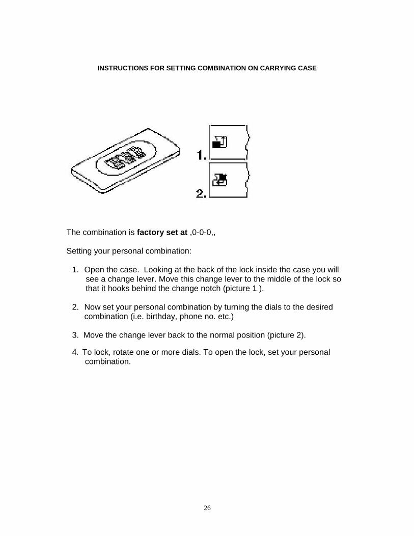
INSTRUCTIONS FOR SETTING COMBINATION ON CARRYING CASE
The combination is factory set at ,0-0-0,,
Setting your personal combination: 1. Open the case. Looking at the back of the lock inside the case you will see a change lever. Move this change lever to the middle of the lock so that it hooks behind the change notch (picture 1 ). 2. Now set your personal combination by turning the dials to the desired
combination (i.e. birthday, phone no. etc.) 3. Move the change lever back to the normal position (picture 2).
4. To lock, rotate one or more dials. To open the lock, set your personal combination.
27
INDEX
ABCD (Valve) Screen
16
Accessories
7
Additional
13
Alarm Enable/Disable
22
Applications
13
Auto Shutdown Battery Feature
21
Basic Components
5
Battery
7
Battery
11
Battery Charger Pod
7
BCH-15 Battery Charger
7
BCH-WTG2
8
Camera
11
Camera
20
Capturing The Spectra Screen Image
19
CFM-15
8
Charging Pod
20
Charging The UP15000
22
Charging The Warble Tone Generator
22
Contact Module
6
dB/Temp
12
DHC-2 Headphones
8
Entering Test Data
19
FFT Display
10
Fields
14
Functions
12
Headset
7
Headset
21
Headset Jack
20
Helpful Hints
22
Home Screen
11
HTS-15
8
ICONS
9
Instructions For Setting The Combination Lock On Carrying Case 26
28
Introduction
5
IR Thermometer
11
Key Features
9
Laser Pointer
11
LRM Long Range Module
6
Main Screen (dB)
12
On/Off button
9
Operation
13
Optional Accessories
8
Overview
9
Pistol Grip Housing
9
Playing/Recording Sounds
23
Quick Change Battery
20
RAM/RAS-MT
7
Recharge Jack
20
Recording a Sound
18
Resetting The On Board Computer
23
Route
12
Rubber Focusing Probe
7
Scanning Module
6
SD Card
10
Selecting Icons for Position on Displays
18
Setting up the Ultraprobe 15,000
11
Settings
12
Setup Modes
12
Setup Screen
12
Standard Accessories
7
Standard Plug-In Modules
6
Stethoscope Extension Kit
7
Storing a Record
18
Suspend
10
Test Module Receptacle
11
TFCM
8
TFSM
8
29
Touch Screen Display
10
Trigger Switch
10
Trisonic- Scanning Module
6
Turn Off
10
Turn on the Ultraprobe 15,000
11
UFMTG-1991
8
Ultraprobe 10,000 Specifications
24
Ultraprobe Kit 5
Using dB/Temp Screen
16
Using Main Screen
15
Using Screens
14
Using Spectra (FFT) Screens
17
Using Temp & Emissivity Screen
16
Using the SD card
10 & 21
Using Valve Screen
16
UWC-15
8
Valve (ABCD) Screen
12
View Record
19
Viewing a Route
19
Viewing and Selecting Icons
14
WTG-1 Warble Tone Generator
7
WTG-2SP Warble Pipe Threaded Tone Generator
8
30
APPENDEX A
Sensitivity Calibration
Ultrasonic Tone Generator Method
Ultraprobe 15000
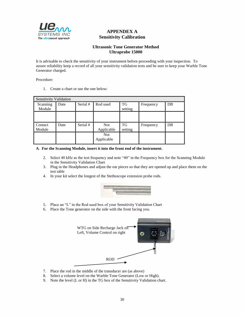
It is advisable to check the sensitivity of your instrument before proceeding with your inspection. To
assure reliability keep a record of all your sensitivity validation tests and be sure to keep your Warble Tone
Generator charged.
Procedure:
1. Create a chart or use the one below:
A. For the Scanning Module, insert it into the front end of the instrument.
2. Select 40 kHz as the test frequency and note “40” in the Frequency box for the Scanning Module
in the Sensitivity Validation Chart
3. Plug in the Headphones and adjust the ear pieces so that they are opened up and place them on the
test table
4. In your kit select the longest of the Stethoscope extension probe rods.
5. Place an “L” in the Rod used box of your Sensitivity Validation Chart
6. Place the Tone generator on the side with the front facing you.
7. Place the rod in the middle of the transducer are (as above)
8. Select a volume level on the Warble Tone Generator (Low or High).
9. Note the level (L or H) in the TG box of the Sensitivity Validation chart.
Sensitivity Validation
Scanning
Module
Date Serial # Rod used TG
setting
Frequency DB
Contact
Module
Date Serial # Not
Applicable
TG
setting
Frequency DB
Not
Applicable
ROD
WTG on Side Recharge Jack on
Left, Volume Control on right
31
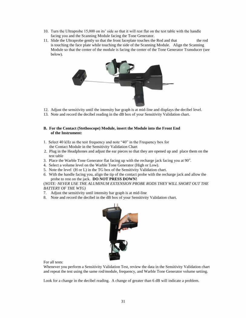
10. Turn the Ultraprobe 15,000 on its’ side so that it will rest flat on the test table with the handle
facing you and the Scanning Module facing the Tone Generator.
11. Slide the Ultraprobe gently so that the front faceplate touches the Rod and that the rod
is touching the face plate while touching the side of the Scanning Module. Align the Scanning
Module so that the center of the module is facing the center of the Tone Generator Transducer (see
below).
12. Adjust the sensitivity until the intensity bar graph is at mid-line and displays the decibel level.
13. Note and record the decibel reading in the dB box of your Sensitivity Validation chart.
B. For the Contact (Stethoscope) Module, insert the Module into the Front End
of the Instrument:
1. Select 40 kHz as the test frequency and note “40” in the Frequency box for
the Contact Module in the Sensitivity Validation Chart
2. Plug in the Headphones and adjust the ear pieces so that they are opened up and place them on the
test table
3. Place the Warble Tone Generator flat facing up with the recharge jack facing you at 90o.
4. Select a volume level on the Warble Tone Generator (High or Low).
5. Note the level (H or L) in the TG box of the Sensitivity Validation chart.
6. With the handle facing you, align the tip of the contact probe with the recharge jack and allow the
probe to rest on the jack. DO NOT PRESS DOWN!
(NOTE: NEVER USE THE ALUMINUM EXTENSION PROBE RODS THEY WILL SHORT OUT THE
BATTERY OF THE WTG)
7. Adjust the sensitivity until intensity bar graph is at mid-line
8. Note and record the decibel in the dB box of your Sensitivity Validation chart.
For all tests:
Whenever you perform a Sensitivity Validation Test, review the data in the Sensitivity Validation chart
and repeat the test using the same rod/module, frequency, and Warble Tone Generator volume setting.
Look for a change in the decibel reading. A change of greater than 6 dB will indicate a problem.

32
14 Hayes Street
Elmsford, NY 10523 USA
Tel: 914-592-1220
Fax: 347-2181
Email: [email protected]
Web page: http://www.uesystems.com
UP15M1010 2010 UE Systems, Inc. All rights reserved