Embed Size (px)
Citation preview

Welcome to the 40th annual EFCLIN Congress
Vilamoura, Portugal
Ken PayneManaging Director, DAC Europe
Specialty IOL’s – A World of Manufacturing Opportunities..
How straightforward are they to make...
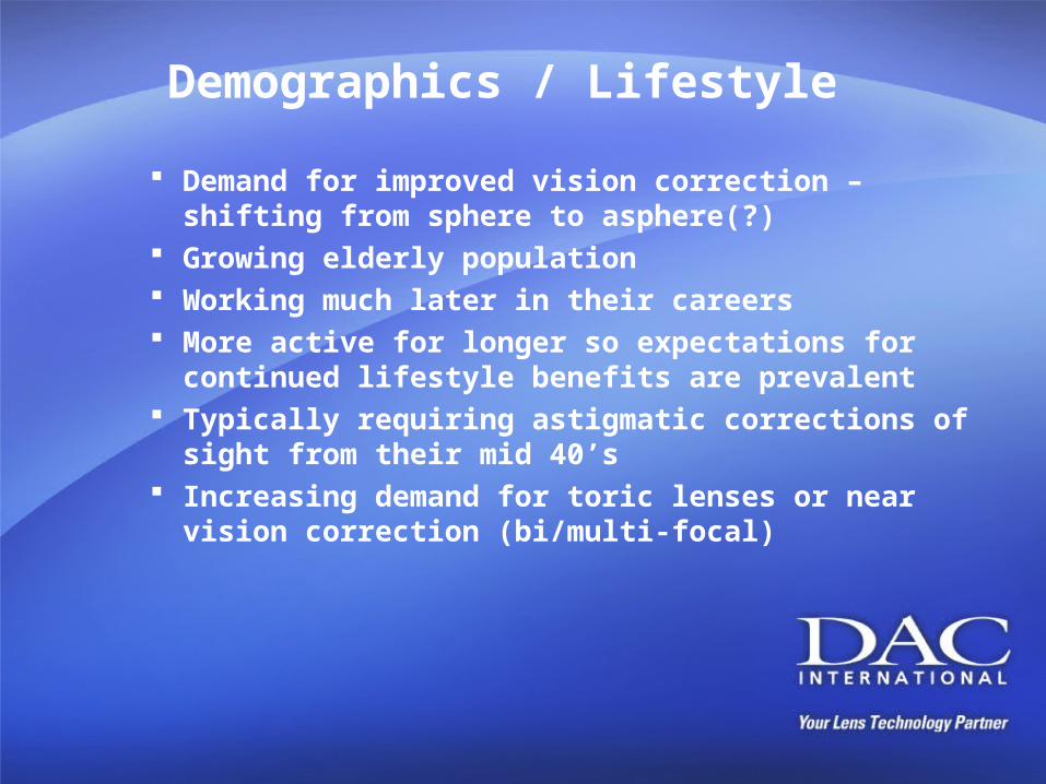
Demographics / Lifestyle
Demand for improved vision correction – shifting from sphere to asphere(?)
Growing elderly population Working much later in their careers More active for longer so expectations for continued
lifestyle benefits are prevalent Typically requiring astigmatic corrections of sight from
their mid 40’s Increasing demand for toric lenses or near vision
correction (bi/multi-focal)
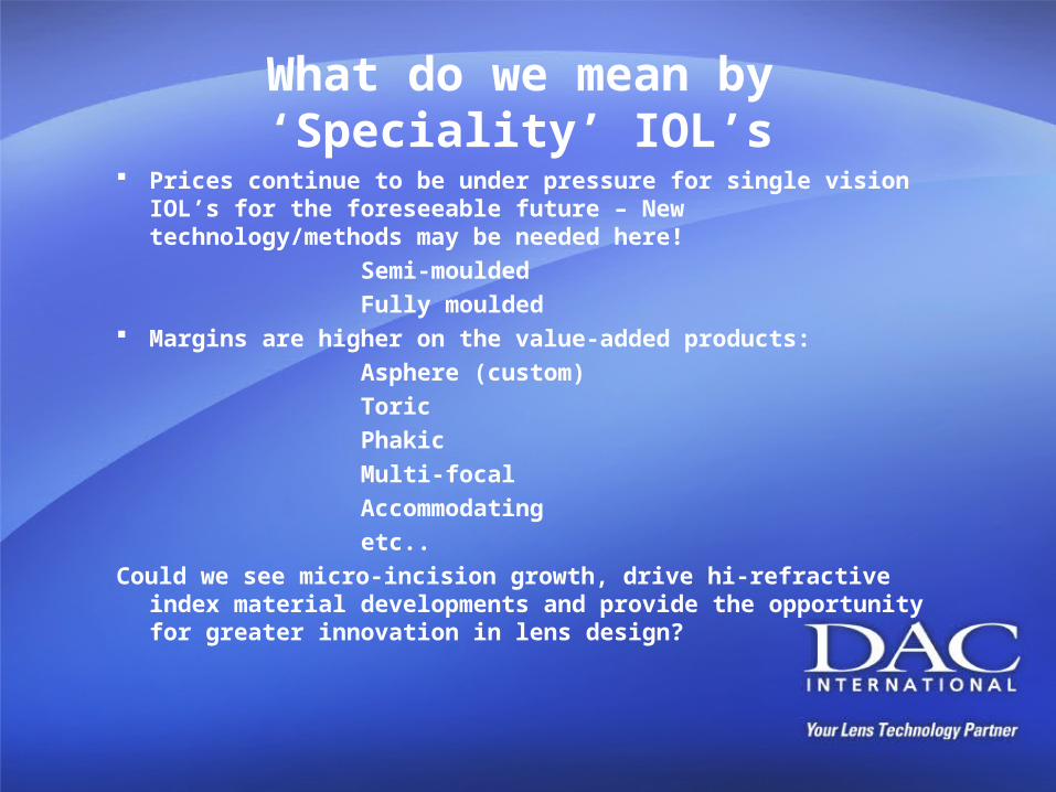
What do we mean by ‘Speciality’ IOL’s
Prices continue to be under pressure for single vision IOL’s for the foreseeable future – New technology/methods may be needed here!
Semi-moulded
Fully moulded Margins are higher on the value-added products:
Asphere (custom)
Toric
Phakic
Multi-focal
Accommodating
etc..
Could we see micro-incision growth, drive hi-refractive index material developments and provide the opportunity for greater innovation in lens design?
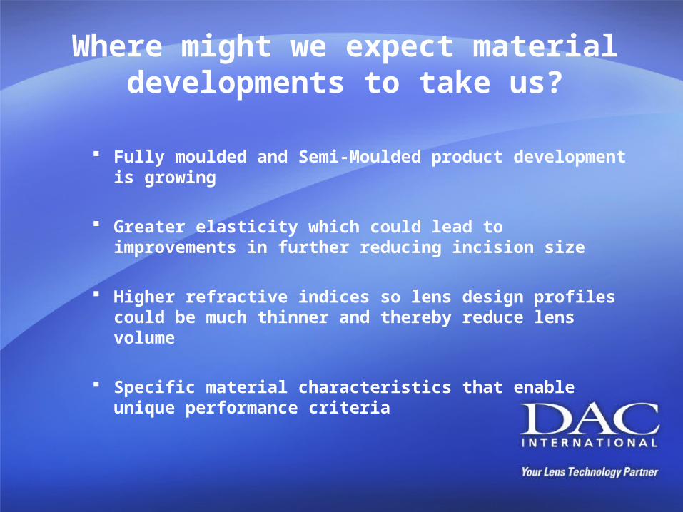
Where might we expect material developments to take us?
Fully moulded and Semi-Moulded product development is growing
Greater elasticity which could lead to improvements in further reducing incision size
Higher refractive indices so lens design profiles could be much thinner and thereby reduce lens volume
Specific material characteristics that enable unique performance criteria
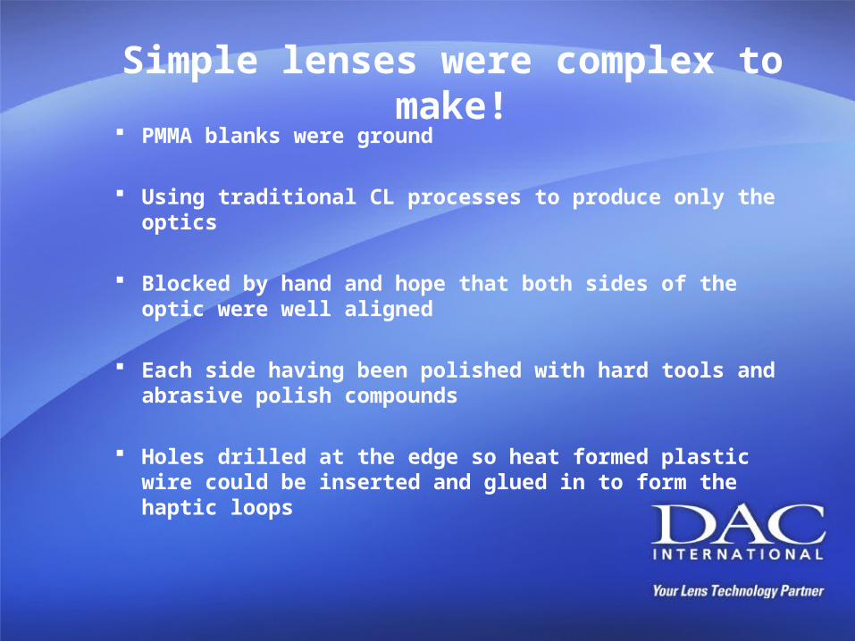
Simple lenses were complex to make!
PMMA blanks were ground
Using traditional CL processes to produce only the optics
Blocked by hand and hope that both sides of the optic were well aligned
Each side having been polished with hard tools and abrasive polish compounds
Holes drilled at the edge so heat formed plastic wire could be inserted and glued in to form the haptic loops
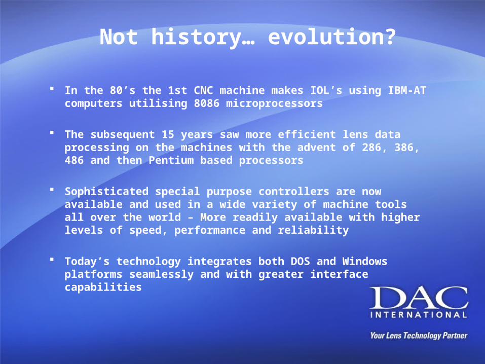
Not history… evolution?
In the 80’s the 1st CNC machine makes IOL’s using IBM-AT computers utilising 8086 microprocessors
The subsequent 15 years saw more efficient lens data processing on the machines with the advent of 286, 386, 486 and then Pentium based processors
Sophisticated special purpose controllers are now available and used in a wide variety of machine tools all over the world – More readily available with higher levels of speed, performance and reliability
Today’s technology integrates both DOS and Windows platforms seamlessly and with greater interface capabilities
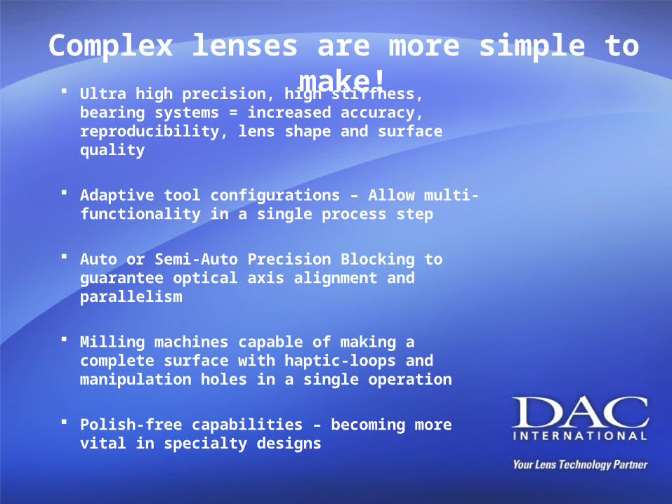
Complex lenses are more simple to make!
Ultra high precision, high stiffness, bearing systems = increased accuracy, reproducibility, lens shape and surface quality
Adaptive tool configurations – Allow multi-functionality in a single process step
Auto or Semi-Auto Precision Blocking to guarantee optical axis alignment and parallelism
Milling machines capable of making a complete surface with haptic-loops and manipulation holes in a single operation
Polish-free capabilities – becoming more vital in specialty designs
IOL – CL – IOL – CL – IOL –CL…
Are these lenses really so different?
Parallels can be drawn….and there’s nothing like the basics…
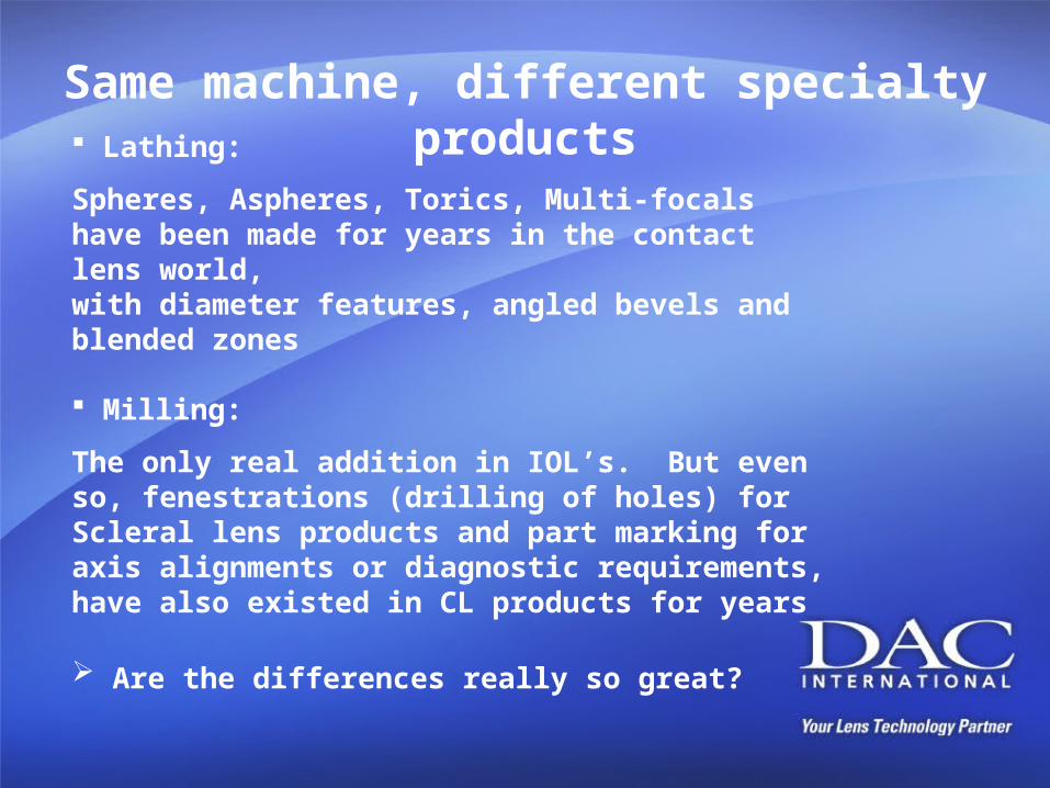
Same machine, different specialty products Lathing:
Spheres, Aspheres, Torics, Multi-focals have been made for years in the contact lens world,with diameter features, angled bevels and blended zones
Milling:
The only real addition in IOL’s. But even so, fenestrations (drilling of holes) for Scleral lens products and part marking for axis alignments or diagnostic requirements, have also existed in CL products for years
Are the differences really so great?

But, Back to Basics…
The equipment to make those speciality lenses still require attention to the key points that will make the difference in the success of your lens…
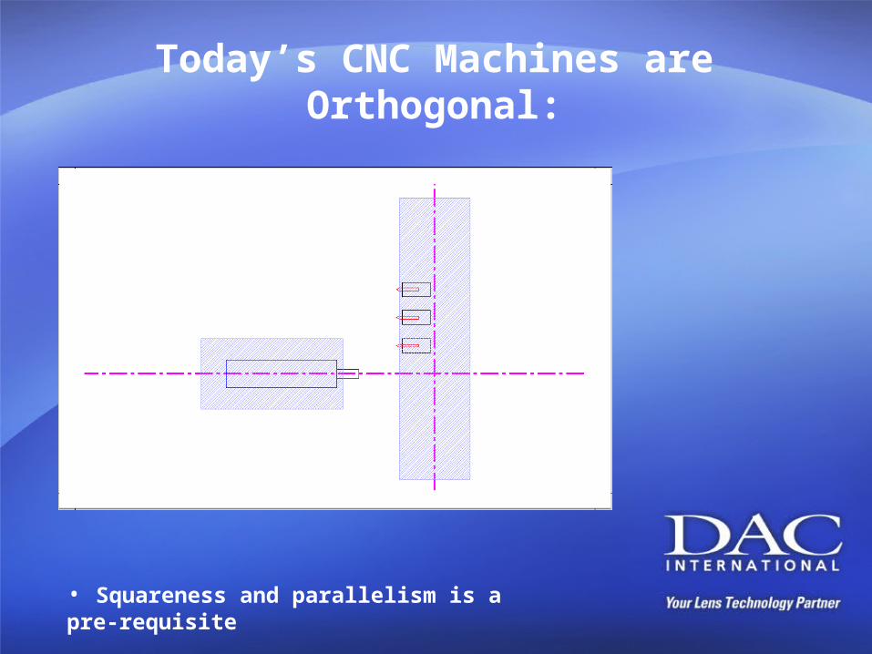
Today’s CNC Machines are Orthogonal:
• Squareness and parallelism is a pre-requisite
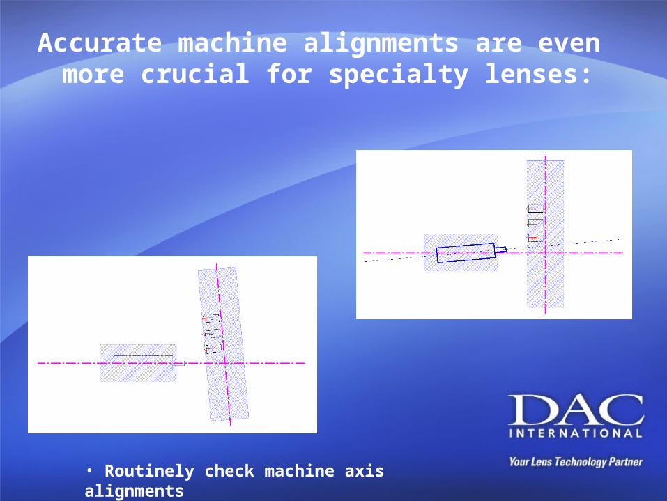
Accurate machine alignments are even more crucial for specialty lenses:
• Routinely check machine axis alignments
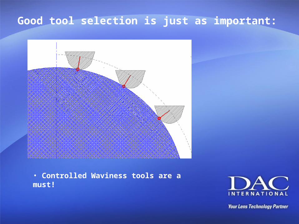
Good tool selection is just as important:
• Controlled Waviness tools are a must!
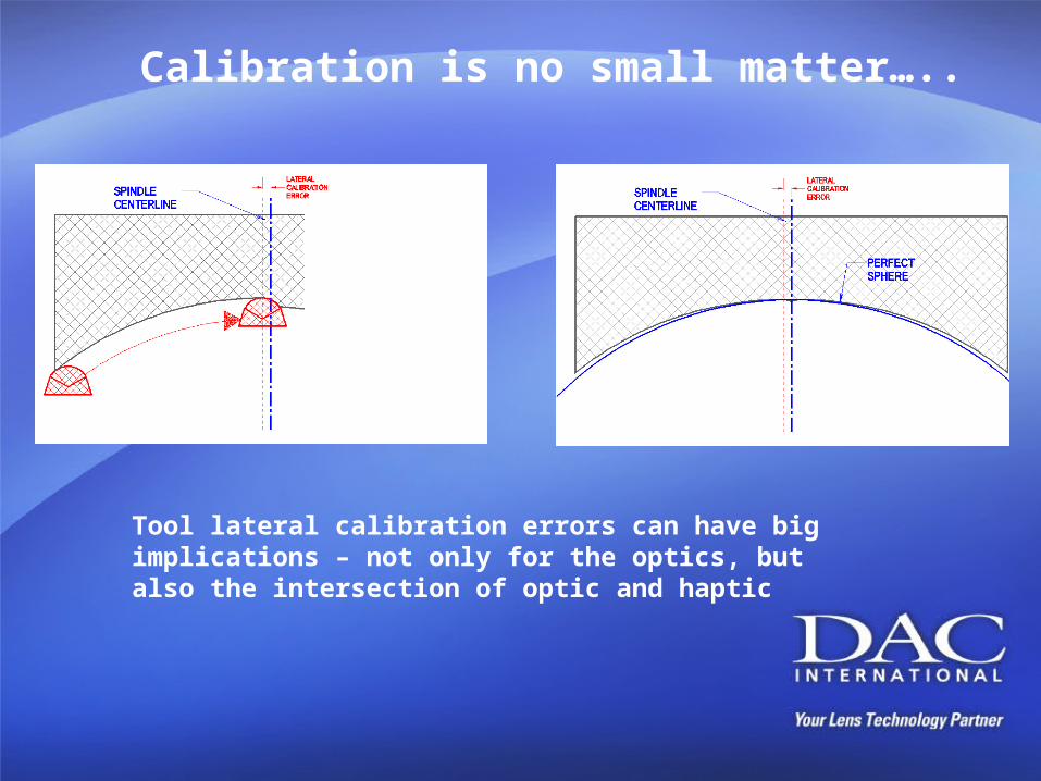
Calibration is no small matter…..
Tool lateral calibration errors can have big implications – not only for the optics, but also the intersection of optic and haptic

Have you been feeling the ‘squeeze’…
Lens deformation is the enemy of high quality optics!
Collet squeeze is one of THE most over-looked problems in ALL lens manufacture and still remains one of the biggest factors in missed target powers and failing reproducibility.
• PMMA was always considered ‘stable’ – but it is compressible
• Spring-packs and air regulators – inconsistent
• Vacuum chucks – limited success
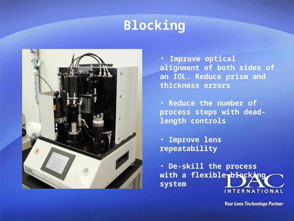
Blocking
• Improve optical alignment of both sides of an IOL. Reduce prism and thickness errors
• Reduce the number of process steps with dead-length controls
• Improve lens repeatability
• De-skill the process with a flexible blocking system
Block your progress at your own peril..!!
Often ignored or even dismissed as a minor part of the lens process, yet…
It’s fundamental at reducing lens shape errors
It provides the optical alignment of both sides of a lens It’s a vital part of maintaining accurate and consistent haptic thickness control It can be used to handle several different materials It’s relatively inexpensive!
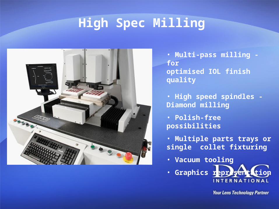
High Spec Milling
• Multi-pass milling - for optimised IOL finish quality
• High speed spindles - Diamond milling
• Polish-free possibilities
• Multiple parts trays or single collet fixturing
• Vacuum tooling
• Graphics representation
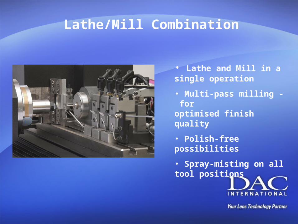
Lathe/Mill Combination
• Lathe and Mill in a single operation
• Multi-pass milling - for optimised finish quality
• Polish-free possibilities
• Spray-misting on all tool positions
Now the machinery fundamentals have been taken care of…
Let’s look at some of the options that could make the difference in your
ability to manufacture specialty IOL’s:
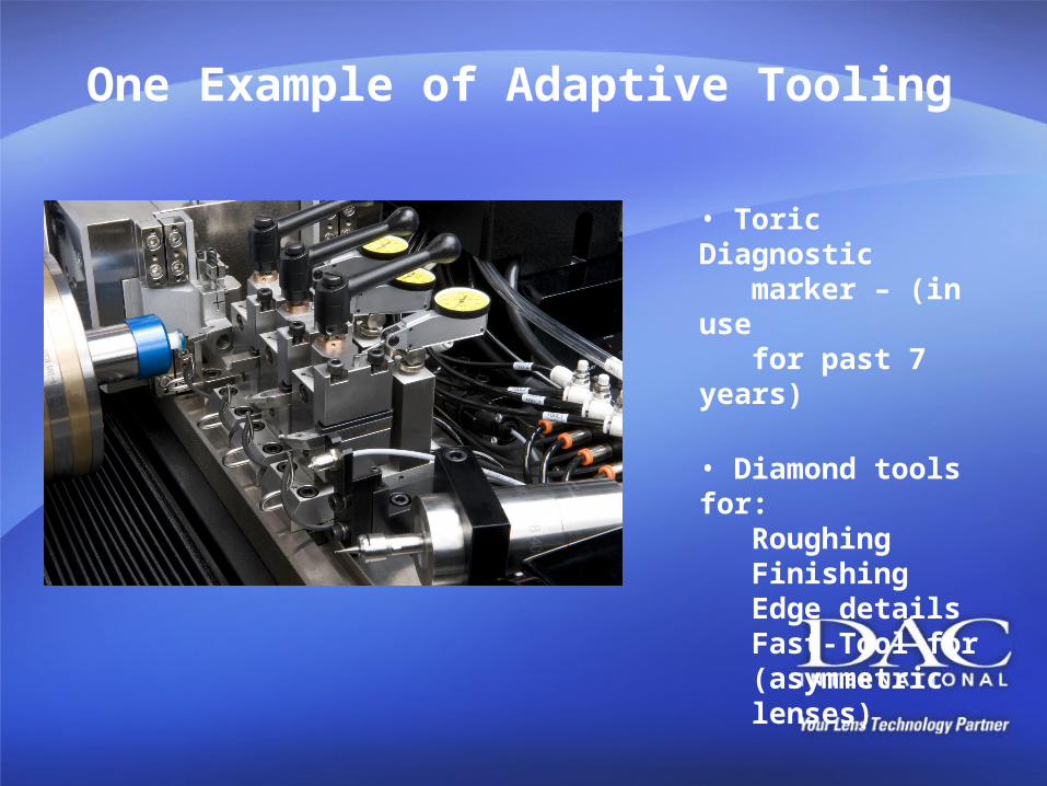
One Example of Adaptive Tooling
• Toric Diagnostic marker – (in use for past 7 years)
• Diamond tools for:RoughingFinishingEdge detailsFast-Tool for (asymmetric lenses)
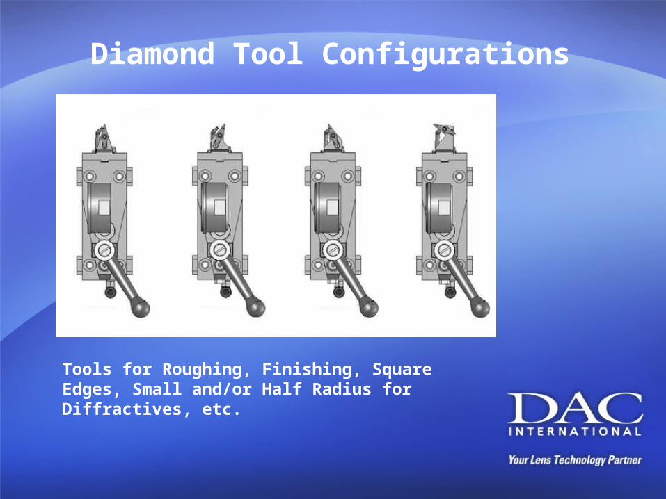
Diamond Tool Configurations
Tools for Roughing, Finishing, Square Edges, Small and/or Half Radius for Diffractives, etc.
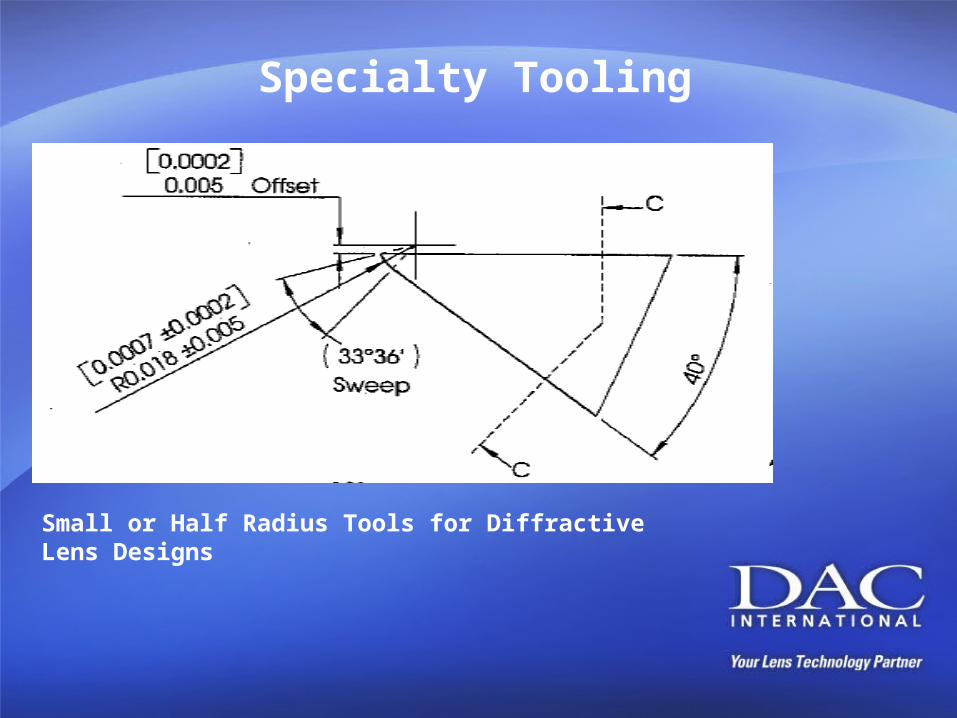
Specialty Tooling
Small or Half Radius Tools for Diffractive Lens Designs
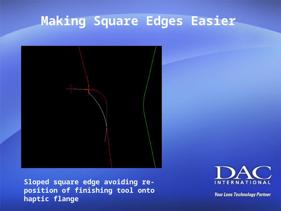
Making Square Edges Easier
Sloped square edge avoiding re-position of finishing tool onto haptic flange
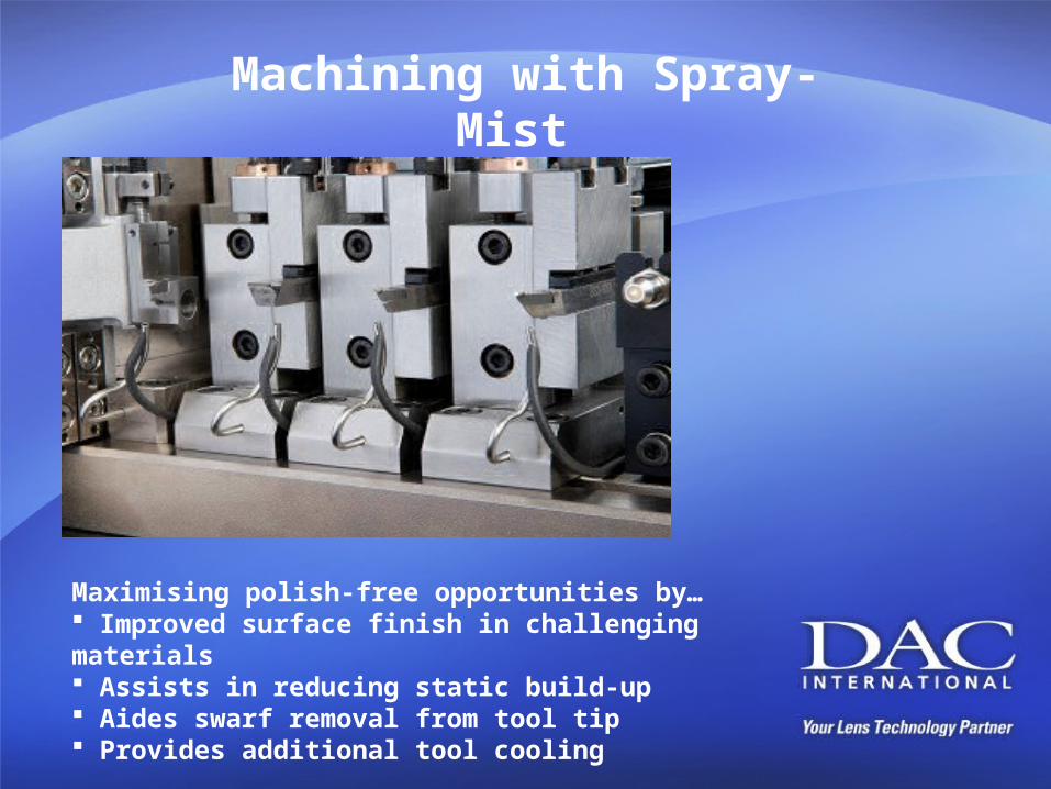
Machining with Spray-Mist
Maximising polish-free opportunities by… Improved surface finish in challenging materials Assists in reducing static build-up Aides swarf removal from tool tip Provides additional tool cooling
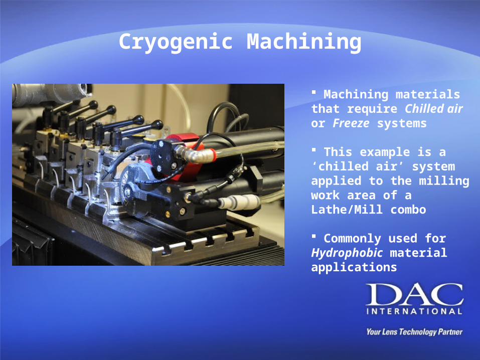
Cryogenic Machining
Machining materials that require Chilled air or Freeze systems
This example is a ‘chilled air’ system applied to the milling work area of a Lathe/Mill combo
Commonly used for Hydrophobic material applications
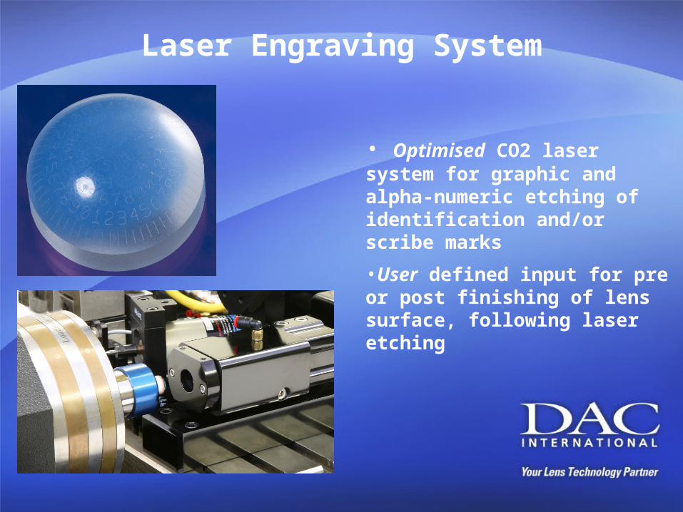
Laser Engraving System
• Optimised CO2 laser system for graphic and alpha-numeric etching of identification and/or scribe marks
•User defined input for pre or post finishing of lens surface, following laser etching
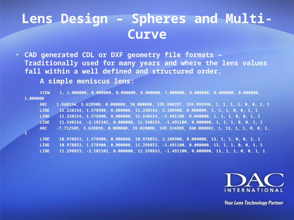
Lens Design – Spheres and Multi-Curve
• CAD generated CDL or DXF geometry file formats – Traditionally used for many years and where the lens values fall within a well defined and structured order.
A simple meniscus lens:
VIEW 1, 1.000000, 0.000000, 0.000000, 0.000000, 1.000000, 0.000000, 0.000000, 0.000000, 1.000000
ARC 1.860154, 5.628900, 0.000000, 10.000000, 339.390297, 359.999990, 1, 1, 1, 1, 0, 0, 1, 1
LINE 11.220154, 1.578900, 0.000000, 11.220154, 2.108900, 0.000000, 1, 1, 1, 0, 0, 1, 1
LINE 11.220154, 1.578900, 0.000000, 11.540154, -1.491100, 0.000000, 1, 1, 1, 0, 0, 1, 1
LINE 11.540154, -2.101101, 0.000000, 11.540154, -1.491100, 0.000000, 1, 1, 1, 0, 0, 1, 1
ARC -7.712589, 5.628898, 0.000000, 19.020000, 349.334888, 360.000003, 1, 13, 1, 1, 0, 0, 1, 1
LINE 10.978853, 1.578900, 0.000000, 10.978853, 2.108900, 0.000000, 13, 1, 1, 0, 0, 1, 1
LINE 10.978853, 1.578900, 0.000000, 11.298853, -1.491100, 0.000000, 13, 1, 1, 0, 0, 1, 1
LINE 11.298853, -2.101101, 0.000000, 11.298853, -1.491100, 0.000000, 13, 1, 1, 0, 0, 1, 1
Lens Design Input – Improving
• CDL or DXF geometry file formats – Define only the basic lens shape with diameters and haptic angles for example.
• The lens design is augmented with additional information retrieved from a DAT file, which will include radius and dioptre values.
• Multi-curve designs required two separate data files…one for the first side of the lens, the other for the second side.
• Add to these files, additional data from Material and Control Tables that define all non-lens parameters such as blank size and machine functions, you can imagine there is a lot of detail for relatively simple lenses.
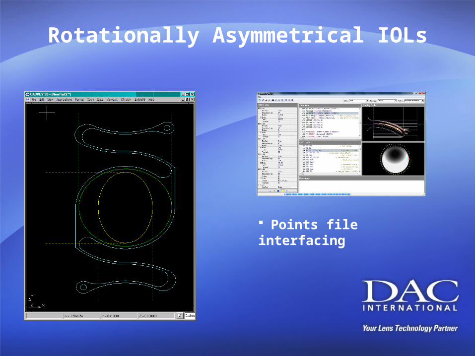
Rotationally Asymmetrical IOLs
Points file interfacing
Lens Design Input - Specialty
• Points files are widely used in the development of Aspheric and Asymmetric optics
• There are several types of points files lens designers use and can be: Binary, Text, Meridian, Spiral, Cloud, etc..
• Software systems enable integration of points files with other CAD generated geometries (haptics for example) for rapid manufacturing implementation
• In the Precision Optics field, optics designers are using specially created optical design software to further reduce the R&D time to develop new optical products into manufacture…..could this be the next generation of specialty IOL manufacture…?
Machining Considerations (I)
• Higher speed Fast-Tools help to reduce cycle times, allowing more time to be dedicated to machining the vital parts of the lens geometry
• Multiple features are best machined in a single pass to avoid steps or surface irregularities
• Specific tool tasks can be defined to optimise square edge features
• Spray Mist systems will enhance surface finish, but will require careful validation
Machining Considerations (II)
• Toric zones are best managed using peripheral carrier curves that blend into square edge developments
• A good blocking system is just as important as the primary lens production equipment
• Semi-moulded lenses may require special colleting/fixturing to ensure there are no distortions created and to retain integrity of good optical alignment
• Software flexibility is enabling greater integration of new lens designs generated as points files
Just a few reasons to keep your technology up to-date:
• Aspheric and Asymmetric lens optics can be degraded with polishing
• Hydrophobic materials are not easily polished
• High accuracy machine slides give greater control and allow multi-pass finishing where material and cutting challenges occur
• Continuous surface machining will reduce zone defects while reducing cycle times
• Tooling flexibility increases lens design feature opportunities
• Optimised shape accuracy and surface quality will improve visual acuity and consistency in your lenses
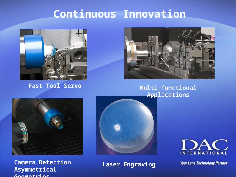
Continuous Innovation
Fast Tool Servo Multi-functional Applications
Camera DetectionAsymmetrical Geometries
Laser Engraving
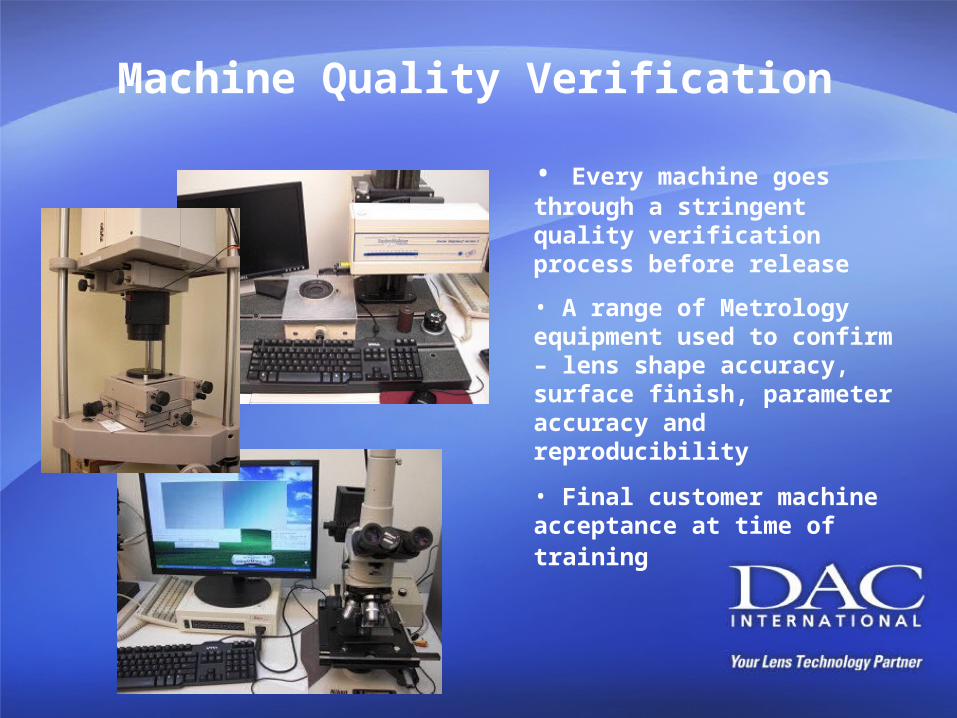
Machine Quality Verification
• Every machine goes through a stringent quality verification process before release
• A range of Metrology equipment used to confirm – lens shape accuracy, surface finish, parameter accuracy and reproducibility
• Final customer machine acceptance at time of training