Embed Size (px)
Citation preview

TO GO DIRECTLY TO THE TECHNICAL ORDER, CLICK ON THE CONTINUE BUTTON.
WELCOME TO TECHNICAL ORDER 00-105E-9, 1 FEBRUARY 2006, REVISION 11.
TO SEE THE SEGMENT INFORMATION CHANGE NOTICE, CLICK ON THE NOTICE BUTTON.
TO CONTACT THE TECHNICAL CONTENT MANAGER , CLICK ON THE CONTACT BUTTON.
CONTINUE
NOTICE
CONTACT
TO NAVIGATE
CLICK ON THEBOOKMARKS ANDCLICK ON THE (+)SYMBOLS, THEN
CLICK ON SUBJECTLINKS TO GO TOSPECIFIC VIEWS
IN THIS SEGMENT.
THIS IS SEGMENT 7 COVERING CHAPTER 6 FROM THE C-130 TO WC-135W.

TECHNICAL ORDER 00-105E-9 TECHNICAL CONTENT MANAGER
WRITTEN CORRESPONDENCE:
HQ AFCESA/CEXFATTN: Fire and Emergency Services Egress Manager139 Barnes Drive Suite 1Tyndall AFB, Florida 32403-5319
E-MAIL: [email protected]
INTERNET: HQ AFCESA Fire and Emergency Services PUBLIC WEB PAGE: http://www.afcesa.af.mil/CEX/cexf/index.asp Safety Supplements: http://www.afcesa.af.mil/CEX/cexf/_firemgt.asp
PHONE: (850) 283-6150DSN 523-6150
FAX: (850) 283-6383DSN 523-6383
For technical order improvements, correcting procedures, and other inquiries,please use the above media most convenient.

This page is provided to notifiy the user of any informational changes made to Technical Order 00-105E-9 in this Segment and the currentRevision. Informational changes will be referenced in the Adobe Reader’s Bookmark tool as a designator symbol illustrated as a <[C]> forquick reference to the right of the affected aircraft. The user shall insure the most current information contained in this TO is used for hisoperation. Retaining out of date rescue information can negatively affect the user’s operability and outcome of emergencies. If the user printsout pages his unit requires, the user shall print the affected page(s), remove and destroy the existing page(s), and insert the newly printedpage(s) in the binder provided for that purpose. A Master of this TO shall be retained in the unit’s library for reference, future printingrequirements and inspections.
CHAPTER AIRCRAFT PAGE EXPLANATION OF CHANGE
SEGMENT 7 INFORMATION CHANGE NOTICE
6 C-130 ALL File updated.6 C-130J ALL File updated.

TO 00-105E-9
Chapter 6 Cover
NOTE
Chapter 6 contains emergency rescue andmishap response information for the following aircraft:
USAF C-5USAF C-7USAF (V)C-9A/CUSAF C-12C/D/FUSAF C-12JUSAF C-17AUSAF C-18USAF C-18DUSAF C-20USAF C-20HUSAF C-21USAF C-22BUSAF C-23AUSAF C-26USAF C-27AUSAF C-32AUSAF C-37AUSAF C-38AUSAF C-40USAF C-130USAF C-130JUSAF C-135USAF NC-135WUSAF RC-135S
USAF RC-135UUSAF RC-135V/WUSAF TC-135SUSAF TC-135WUSAF WC-135CUSAF WC-135WUSAF (V)C-137USAF C-141USAF NC-141AUSAF C-212USAF KC-10A

C-130T.O
. 00-105E-9
C-130.1
AIRCRAFT PAINT SCHEME
C-130T.O
. 00-105E-9
C-130.
AIRCRAFT DIMENSIONS
132’ 7” ( 40.41M)WINGSPAN
PROP TO NOSE 29’ 1”
TAIL SPAN 52’ 8”
PROPDIAMETER 13’ 6”
STATIC GROUND LINE1’ 10”
14’ 3”
6’ 7”5’10”
2 30 DIHEDRAL0
FLIGHT REFERENCE LINE 38’10”(11.68M)
HEIGHT
15’ 0”
11’ 6”29’ 5”5’
97’ 9” (29.79 M)LENGTH
2

C-130T.O
. 00-105E-9
C-130.
FORWARD FUSELAGE (BOTH SIDES)
NOTE: Penetration point should be approxiamately 12 inches above W.L. 146 (floodline) and centered between F.S. 337 segment and F.S. 357 segment.
AFT FUSELAGE (BOTH SIDES)
NOTE: Penetration point should be approximately 12 inches above W.L. 146 (floodline) and a 1/4 of the distance between F.S. 677 ring segment and F.S. 697 ring segment.
SKIN PENTRATION POINTS
3

C-130T.O
. 00-105E-9
C-130.
SKIN PENTRATION POINTS- Continued
Fire access panels may have accumulated flammable dripping fluids. Use caution to avoid these fluids when opening the spring loaded access panel.
NOTE: Penetration points are the same on all four engine nacelles.
RIGHT SIDE
LEFT SIDE
RIGHT SIDE
APPLICABILITY:C-130B/E/H/J, HC-130B/H/N/P, LC-130H
APPLICABILITY:C-130A/D
LEFT SIDE
4
FIRE ACCESS PANEL
WARNING

C-130T.O
. 00-105E-9
C-130.
AIRFRAME MATERIALS
5
ALUMINUM
STEEL (TO INCLUDE LANDING GEAR)
OTHER - FIBERGLASS
AIRFRAME MATERIALS UP TO THE J MODEL

C-130T.O
. 00-105E-9
C-130.
AIRCRAFT HAZARDS
6 NOTE: During engine operation, Propeller Wake and Turbine Exhaust Wakes are superimposed and, at full power, produce a wake of 69 knots 500 feet (152 m) aft of the propellers.
TURBINE DISINTEGRATION ZONE
ENGINEEXHAUST
PROP BLAST
PROPELLER WARNING STRIPE
GTC AIR NTAKE
DISTANCE FROM EXHAUST - FEET 4 25 50 100 “ - METERS 1.22 7.62 15.24 30.48EXHAUST TEMPERATURE 800 F (426.7C) 100 F (37.8C)
PROPELLER INFLOW AND WAKE
TURBINE EXHAUST
GTC EXHAUST
C-130T.O
. 00-105E-9
C-130.7
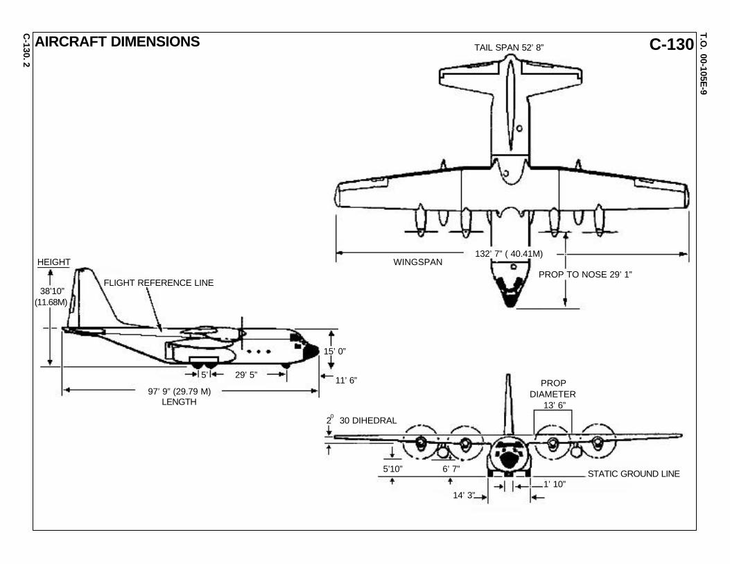
SPECIAL TOOLS/EQUIPMENTPower Rescue SawFire Drill IIAIRCRAFT ENTRY-ALL MODELS1. NORMAL ENTRY
Forward hatch (2a), right side of fuselage, is in close proximity of right inside turbo propeller. Avoid if propeller/engine is running. This hazard could cause loss of life! Not for entry or aircrew extraction until engine is shutdown. Same for left side if applicable model is in use.
NOTE: On AC-130 aircraft equipped with interior electronic compartment, gain entry using troop door right aft side of aircraft.
CAUTION
Verify aircraft is depressurized prior to entry. If verification can not be made, use any means possible to penetrate aircraft skin to vent pres- sure, then enter aircraft. Places to penetrate: entry door, side escape hatches, port hole windows, paratroop doors, emergency escape hatches, and designated cut-in areas. Pressurization is 15.6 PSI.
a. Rotate crew entry door handle, located forward left side of fuselage, counterclockwise and open door outward and down.b. Rotate troop door handle, located aft on both sides of fuselage, clock- wise and push door inward and up until locked in open position.
2. EMERGENCY ENTRY
a. Pull release handle and push inward on four hatches located forward, center, and aft top of fuselage, and fuselage forward right side.
3. CUT-IN
a. Cut-in areas are located on each side of fuselage, above and forward of each troop door.
NOTE: On HC-130H/N/P aircraft, right emergency entry door may be blocked by an equipment bin. On these aircraft, an identical emergency entry door is located on the left side of the aircraft.
WARNING
FLARE LAUNCHER(AC-130H)
450
450
1360
FIRE BOTTLES
500 OR 1800 KC-130F
SIGNAL FLARES
OXYGEN
OXYGEN
OXYGEN
LIQUIDOXYGEN
BATTERYFUELC-130E,H,N,P
1360
FUELC-130B,E,H
FUEL TANKS
FUELC-130A
FLARELAUNCHER(AC-130H)
2aHATCHES
2aDITCHINGHATCHHANDLE
1bAFT TROOPDOOR HANDLE
1aCREW ENTRYDOOR HANDLE 3a
CUT-IN
OPEN
LOCKED

C-130T.O
. 00-105E-9
C-130.8
OVERHEAD CONTROL PANEL
1cBATTERYSWITCH
1cBATTERYSWITCH
A MODEL
1bBATTERY ENGINESTART SWITCH
GTC T-HANDLE1bFIRE T-HANDLES
1aCONDITION LEVERSFEATHER POSITION
CONTROL PEDESTAL
ENGINE SHUTDOWN AND AIRCREW EXTRACTIONWARNING
Avoid hazards of running aircraft by entering through rear troop doors.
NOTE: DO NOT remove battery power before activating the fire T-handles.
1. ENGINE SHUTDOWN
a. Position condition levers, located on control pedestal between forward crew seats, aft to FEATHER position. Open safety guard of bus-tie switch, located on the overhead panel above right seat arm rest, and turn bus-tie switch to ON position.
NOTE: If switch is left in OFF position, pulling fire T-handles will only arm fire extinguishing system and not close fuel, oil and hydraulic fluid valves at engine fire walls.
b. Pull fire T-handles, located on overhead panel, out of its detent and the out position.
IN CASE OF ENGINE FIRE: Pull fire T-handles to the out position, then depress and hold battery engine start switch, located below and between #1 and #2 T-handles for 5 seconds, then release battery engine start switch. Only direct agent to engine indicating fire. T-handle may have to be pushed in and pulled out to redirect agent. A three position toggle switch between #2 and #3 T-handles discharges the agent. Center position of toggle switch is OFF. Holding the switch to the UP position will discharge the first of two halon filled fire bottles. If more agent is needed, position the toggle switch to the DOWN position to discharge the second fire bottle. There are only two fire bottles for this extinguishing system. Use them wisely.
NOTE: If APU/GTC is operating, pull GTC T-Handle. GTC - ground takeoff handle runs the APU system.
c. Disconnect battery, located forward of crew entrance door or turn battery switch, located on overhead control panel, clockwise to OFF position. On the C-130A turn switch counterclockwise to OFF position.
2. AIRCREW EXTRACTION
a. Release latch on lap belt and remove shoulder harness from crewmember’(s).
NOTE: If seat track is not damaged during crash landing, use adjustable seat control to move seat in aft position when removing crewmember. Passenger seats do not have shoulder harness.
1 2 3 * 4

C-130T.O
. 00-105E-9
C-130.9
OXYGEN SYSTEM SHUTDOWN E AND H MODELOXYGEN SHUTOFFVALVE
FORWARD CARGO COMPARTMENT BULKHEAD
LC-130H MODELOXYGEN SHUTOFFVALVE @ F.S. 627
B AND HC MODELOXYGEN SHUTOFF VALVES
NOTES:· To reduce fire damage in the cockpit area
CLOSE oxygen manual supply valve(s).Ensure all occupants have been evacuatedbefore closing valve(s).
· On B and HC model aircraft have twoserrated knob shutoff valves. One located oneach side of the fuselage directly below thestorage cylinders. Turn knobs clockwise tothe OFF position.
· On E and H model aircraft have one serratedknob shutoff valve. It is located on the fwdcargo compartment bulkhead right side.Turn knob clockwise to the OFF position.
· On LC-130H model aircraft have one serratedknob shutoff valve. It is located at F.S. 627.
TYPICAL OXYGENSHUTOFF VALVEWITH SERRATED KNOB
TYPICAL OXYGENSHUTOFF VALVE

C-130T.O
. 00-105E-9
C-130.10
OXYGEN SYSTEM APPLICABILITY:EC-130E ABCCC (III)NOTE:
The oxygen system supply of theC-130E and H aircraft is carried in aliquid oxygen converter of 25 litercapacity, shock mounted in the rightside of the nose wheel well. A ca-pacitance-type liquid oxygen quan-tity indicating system is providedwith a gage on the co-pilot’s side ofthe main instrument panel, togetherwith a low level warning light. Theconverter supplies gaseous oxygento a system consisting of plumbinglines connected to ten regulators andfour recharging connections. Theregulators are located in the flightstation and cargo compartment atpotential crew stations. Two re-charging connections from whichportable oxygen bottles can be re-filled which are located in the cargocompartment. The converter is filledwith liquid oxygen through a valveon a panel accessible from outsidethe aircraft on the right side of thefuselage nose. A vent system is pro-vided to vent the system overboardduring fitting and to control systempressure during operation. So longas there is any liquid in the converter,system pressure of gaseous oxygenis maintained within the limits of 305(+/-10) PSI. When system is not inuse, pressure may indicate 380 to430 PSI.
PARATROOPDOOR
REGULATOR(TYPICAL)
CREWDOOR
OVERBOARDRELIEF LINE
LIQUIDOXYGENFILLINGLINE
GASLINE
DRAINLINE
LIQUIDOXYGENDRAINVALVE
OVERBOARD DRAIN
COMBINATION VALVE
OVBDVENT
BUILDUP LINE
CONVERTER NO. 1
SUPPLY LINE
HEATEXCHANGER
CHECKVALVE
EMERGENCYSHUTOFFVALVE
FLEX LINETO CAPSULE
OVBDDRAIN
OVBDVENT
COMBINA-TION VALVE
LOXDRAINVALVE
LOXFILLINGLINE
CONVERTER NO. 2
OVBDDRAIN
BUILDUP LINE
SUPPLYLINE
GASLINE
WHEELWELL
HEATEXCHANGER
PORTABLEOXYGENUNIT(TYPICAL)
CHECKVALVE
LC-130H MODELOXYGEN SHUTOFFVALVE (STATION 627)

C-130T.O
. 00-105E-9
C-130.11
GUNSHIP CONFIGURATIONSNOTE: AC-130A is retired. The H model is a modified E model.
Crew total - 13 including pilot, co-pilot, navigator, flightengineer, fire control, officer, electronics warfare officer,two sensor operators, an illuminator and five gunners.
Hazards:Defensive aids - electronic countermeasures, chaff andflares.2,000 watt night target illuminator.7.62 miniguns and ammo racks removed.
NOTE: The AC-130U model is a modified H model.
Crew total - including flight crew and loaders - 13Cabin Positions - Prone observer - rear ramp - 1Starboard observer - aft of flight deck - 1Battle management consoles - 7
Hazards:Defensive aids - similar to AC-130HModified fuel tank pylons300 chaff bundlesThree flare launchers under fuselage.Multiple electronic equipment with various computers.
FLARELAUNCHER
20 MM AMMO
40MM AMMO/105 MM AMMO
20 MM CANNONS2,500 RPM
105 MM CANNON4 RPM
40 MM CANNON100 RPM
M16 RIFLERACK
PRONE AFT SCANNER
PARATROOPDOOR40 MM/105 MM
AMMOSTORAGE
CREWREST
CO-PILOT
BATTLEMANAGEMENTCENTER
ENGINEER
FORWARDOBSERVER
CRASHSEATS (4)
105 MM GUN
40 MM GUNLIVEAMMO DUMP
25 MM GUN 6 BARRELGATLING 3,000 ROUNDS
FLIGHTDECK
BUNKGALLEY
PILOT
INFRAREDSENSOR
RADAR
ALL LIGHT LEVEL TV
APPLICABILITY:AC-130H
APPLICABILITY:AC-130U

C-130T.O
. 00-105E-9
C-130.12
ARMOR INSTALLATION ANDPROTECTION LOCATIONS
APPLICABILITY:AC-130U
APPLICABILITY:C-130E ABCCC (II)
CABIN ARRANGEMENT ANDPERSONNEL LOCATIONS
CREW RESTCOMPARTMENTSIDEWALL
25 MM AMMOSTORAGE(FRAGMENTSUPPRESSION CURTAIN)
40 MM/105 MMAMMO STORAGE
BMC
SPECTRA BACKING
SILICONE CARBIDECERAMIC TILES
“E” GLASS TYPE VIII CLOTH(FIBERGLASS) SPALLSHIELDON THREAT SIDE
LIGHTWEIGHT CERAMIC ARMOR PANEL
RUDDER &ELEVATORACTUATORS
HYDRAULICSYSTEM
FORWARDPRESSUREBULKHEAD
RAMP
AUXILIARYHYDRAULICSYSTEM
NOSEWHEELWELL
LOXBOTTLEARMOR
UNDERFLOOR
RIGHTSCANNER& CREWRESTCOMPART-MENT
FLIGHTDECKFLOOR
AFT PRESSUREBULKHEAD
AFTSCANNER’SCOUCH 40 MM/105 MM
SIDEWALL FLIGHTDECKSIDEWALL
HYDRAULICSYSTEM
25 MM GUNSIDEWALL
DOOR LOCKEDFROM INSIDE
LEFT CAPSULEDOORLEFT HAND
PARATROOPDOOR
FORWARDCAPSULEDOOR
FLIGHTDECK
CREWENTRANCEDOOR
CAPSULE
* DENOTES CREW POSITION IN CAPSULE

C-130T.O
. 00-105E-9
C-130.13
APPLICABILITY:EC-130E ABCCC (III)
CABIN ARRANGEMENT ANDPERSONNEL LOCATIONS-Continued
OVERHEAD ESCAPE HATCH LOCKED FROM INSIDE
PARATROOP DOORSFLIGHTDECK
FORWARDCAPSULEDOOR
CREW ENTRANCE DOOR
CAPSULE PARATROOPDOORS
CAPSULE DOORS AFT EXIT
CARGORAMP
FWD
OXYGEN SHUTOFF ABCCCCOMPARTMENT
CREW ENTRANCE DOOR
OXYGEN SHUTOFFFOR AIRCRAFT
* DENOTES CREW POSITIONS** CUT-IN AREAS ARE LOCATED ON EACH CAPSULE DOOR

C-130T.O
. 00-105E-9
C-130. The C-130 can be configured with the Modular Airborne Fire Fighting System, or MAFFS, to perform its firefighting mission. MAFFS is a self-contained,
reusable 3,000-gallon fluid dispersal system that can be installed inside a C-130, quickly changing its role from airlift to fire suppression. A MAFFS-equipped C-130 can discharge its entire load of fire retardant in under five seconds.
There are four Air Force units that fly MAFFS missions as part of a joint program with the U.S. Department of Agriculture Forest Service. Since theprogram’s inception in the early 1970s, MAFFS-equipped C-130s have flown more than 6,500 missions, dropping over 10 million gallons of fire retardantagainst fires throughout the United States, Europe and Asia.
MISSION CONFIGURATION
Tactical Airlift All Aerial Tanker KC-130B, KC-130F, KC-13H, HC-130H(N), HC-130N, HC-130P, KC-130R, KC-130T
Command & Control EC-130E (ABCCC), EC-130G, & EC-130Q
Maritime Patrol C-130H-NP/PC-130H
Special Operations MC-130E & MC-130H
Search & Rescue SC-130B/HC-130B, HC-130E, HA-130H, HC-130H(N), HC-130N, & HC-130P
Humanitarian Relief All Staff/VIP Transport VC-130B & VC-130H
Reconnaissance RC-130B
Airborne Hospital C-130E (AEH)
Arctic and Anarctic Support C-130BL/LC-130F, C-130D, LC-130H, & LC-130R
Drone Control GC-130A/DC-130A, DC-130E, & DC-130H
Electronic Warfare EC-130E (CL), EC-130E (RR), EC-130H
Space and Missile Operations JC-130A, JC-130B, & NC-130H
Test and Evaluation NC-13A, NC-130B, JC-130E, NC-130E, JC-130H, & RC-130S
Weather Reconnaissance WC-130B, WC-130E, WC-130H
Gunship AC-130A, AC-130E, AC-130H, & AC-130U
MODULAR AIRBORNE FIRE FIGHTING SYSTEM
14
OTHER C-130 MISSION CONFIGURATIONS

C-130JT.O
. 00-105E-9
C-130J.1
AIRCRAFT PAINT SCHEME
C-130JT.O
. 00-105E-9
C-130J.
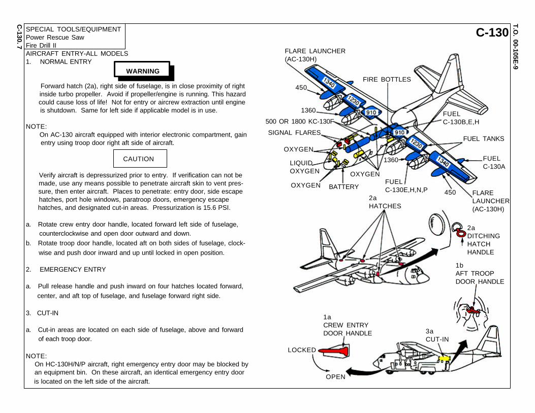
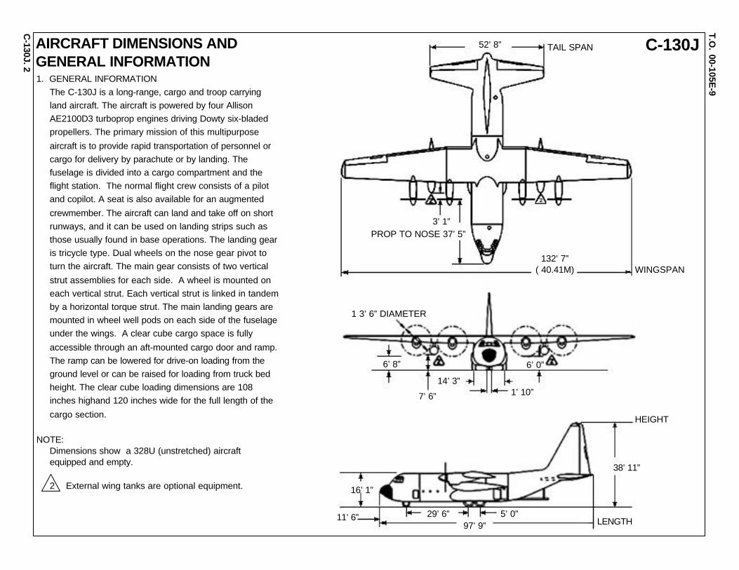
1. GENERAL INFORMATIONThe C-130J is a long-range, cargo and troop carryingland aircraft. The aircraft is powered by four AllisonAE2100D3 turboprop engines driving Dowty six-bladedpropellers. The primary mission of this multipurpose
aircraft is to provide rapid transportation of personnel orcargo for delivery by parachute or by landing. Thefuselage is divided into a cargo compartment and theflight station. The normal flight crew consists of a pilotand copilot. A seat is also available for an augmented
crewmember. The aircraft can land and take off on shortrunways, and it can be used on landing strips such asthose usually found in base operations. The landing gearis tricycle type. Dual wheels on the nose gear pivot toturn the aircraft. The main gear consists of two vertical
strut assemblies for each side. A wheel is mounted oneach vertical strut. Each vertical strut is linked in tandemby a horizontal torque strut. The main landing gears aremounted in wheel well pods on each side of the fuselageunder the wings. A clear cube cargo space is fully
accessible through an aft-mounted cargo door and ramp.The ramp can be lowered for drive-on loading from theground level or can be raised for loading from truck bedheight. The clear cube loading dimensions are 108inches highand 120 inches wide for the full length of the
cargo section.
NOTE:Dimensions show a 328U (unstretched) aircraftequipped and empty.
2 External wing tanks are optional equipment.
AIRCRAFT DIMENSIONS ANDGENERAL INFORMATION
52’ 8”
132’ 7”( 40.41M) WINGSPAN
PROP TO NOSE 37’ 5”
2
3’ 1”
1 3’ 6” DIAMETER
6’ 8”
14’ 3”
6’ 0”
1’ 10”7’ 6”
38’ 11”
HEIGHT
16’ 1”
11’ 6” 29’ 6”97’ 9”
5’ 0”LENGTH
TAIL SPAN

C-130JT.O
. 00-105E-9
C-130J.
AIRCRAFT DIMENSIONS-ContinuedNOTE:
Dimensions show a 328V (stretched) aircraft equippedand empty.
2 External wing tanks are optional equipment.
3
TAIL SPAN
132’ 7”( 40.41M) WINGSPAN
PROP TO NOSE 37’ 5”
3’ 1”
1 3’ 6” DIAMETER
6’ 8”
14’ 3”
6’ 0”
1’ 10”7’ 6”
38’ 11”
HEIGHT
15’ 11”
11’ 6” 37’ 10”112’ 9”
5’ 0”LENGTH
52’ 8”

C-130JT.O
. 00-105E-9
C-130J.
FORWARD FUSELAGE (BOTH SIDES)
NOTE: Penetration point should be approxiamately 12 inches above W.L. 146 (floodline) and centered between F.S. 337 segment and F.S. 357 segment. AFT FUSELAGE (BOTH SIDES)
NOTE: Penetration point should be approximately 12 inches above W.L. 146 (floodline) and a 1/4 of the distance between F.S. 677 ring segment and F.S. 697 ring segment.
SKIN PENTRATION POINTS
4

C-130JT.O
. 00-105E-9
C-130J.
SKIN PENTRATION POINTS- ContinuedNOTE: Penetration points are the same on all four engine nacelles.
Fire access panels may have accumulated flammable dripping fluids. Use caution to avoid these fluids when opening the spring loaded access panel.
RIGHT SIDE
LEFT SIDE
5
FIRE ACCESS PANEL
WARNING

C-130JT.O
. 00-105E-9
C-130J.
AIRFRAME MATERIALS
6
ALUMINUM
STEEL (TO INCLUDE LANDING GEAR)
OTHER - FIBERGLASS
Engines are equipped with 6 propeller blades that are molded andmanufactured from carbon and glass fiber, reinforced with a polyure-thane foam, and have a polyurethane elastomer outer coating.
The inboard elevator counterbalance weight is cast Depleted Uranium(DU). The DU is to be replaced by a alternate material selection ofSintered Tungsten. This modification will start with aircraft serialnumber 5536.
1. AIRFRAME MATERIALS
12”
6.12”
3”
Green shaded area represents added volume tomaintain mass as DU.
CAST DU COUNTER WEIGHT
SINTERED TUNGSTENCOUNTER WEIGHT
COUNTER-BALANCEASSEMBLIES
TUBEASSEMBLY
SUPPORT
COUNTERBALANCE WEIGHT
CARBON FIBER (FLAPS)32 GRAPHITE-EPOXY (TRAILING EDGE PANELS)
NICKLE (PROPEDGE GUARD)
PROPBLADE
PROPEDGEGUARD
DEICEBOOT
FWD

C-130JT.O
. 00-105E-9
C-130J.
AIRFRAME MATERIALS-Continued
7 1. AIRFRAME MATERIALS - Continued
Fowler-type wing flaps are located along the trailing edges ofthe wings. Two flaps are used per side. The flaps extend fromthe wing root to the aileron. Each section of flap is all compos-ite, constructed of a span-wise beam, ribs, and upper and lowerskin panels. The flaps are mounted on carriages that roll oncurved tracks. Two carriage assemblies support each centerwing flap. Five carriage assemblies support each outer wingflap. The tracks extend aft from the trailing edge of the wing.The flaps are extended and retracted by jackscrew actuators.With the flaps installed, emergency stops are mounted at theaft end of the tracks. The flap’s structure and skin are ofcomposite construction consisting of prepregnated carbon fiberand glass fabric.
The upper skin panels are of composite construction, consist-ing of prepregnated carbon fiber and glass fabric. The doors aremade up of outer skins bonded to beaded inner frames by aspecification MIL-A-5090, Type I adhesive, or equivalent.
The outer wing trailing edge provides fairing for the wing boxbeam and provides structural support for the outer wing flaps.The trailing edge skin panels are of composite construction,carbon/epoxy prepregnated materials.
FWD FWD
VIEW LOOKING UP VIEW LOOKING DOWN
COMPOSITE PANELSTRAILING EDGELOWER SURFACEOUTER WING
COMPOSITE PANELSTRAILING EDGELOWER SURFACECENTER WING
COMPOSITE PANELSTRAILING EDGELOWER SURFACECENTER WING
COMPOSITE PANELSTRAILING EDGELOWER SURFACEOUTER WING
COMPOSITE PANELSTRAILING EDGEUPPER SURFACEOUTER WING
COMPOSITE PANELSTRAILING EDGEUPPER SURFACEOUTER WING
COMPOSITE PANELSTRAILING EDGEUPPER SURFACECENTER WING
COMPOSITE PANELSTRAILING EDGEUPPER SURFACECENTER WING
FUS STA737.00
BL0.00
UPPER AND LOWER COMPOSITE PANELS
CENTER WINGCOMPOSITE PANEL(TYP)
INS/GPSANTENNA
OVERHEAD WING SUPPORT
FWD
VIEW LOOKING DOWN
C-130JT.O
. 00-105E-9
C-130J.
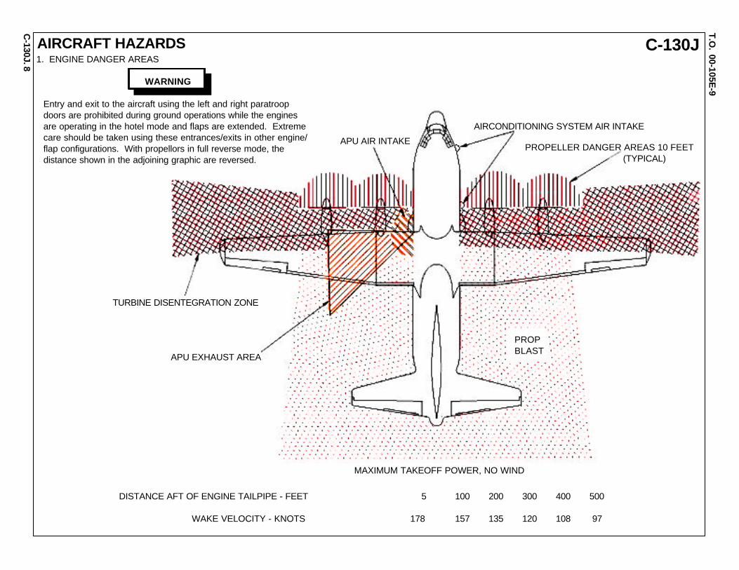
AIRCRAFT HAZARDS
8
APU AIR INTAKE
AIRCONDITIONING SYSTEM AIR INTAKE
PROPELLER DANGER AREAS 10 FEET (TYPICAL)
PROPBLAST
TURBINE DISENTEGRATION ZONE
APU EXHAUST AREA
MAXIMUM TAKEOFF POWER, NO WIND
DISTANCE AFT OF ENGINE TAILPIPE - FEET 5 100 200 300 400 500
WAKE VELOCITY - KNOTS 178 157 135 120 108 97
WARNING
Entry and exit to the aircraft using the left and right paratroopdoors are prohibited during ground operations while the enginesare operating in the hotel mode and flaps are extended. Extremecare should be taken using these entrances/exits in other engine/flap configurations. With propellors in full reverse mode, thedistance shown in the adjoining graphic are reversed.
1. ENGINE DANGER AREAS

C-130JT.O
. 00-105E-9
C-130J.
AIRCRAFT HAZARDS-Continued
9
WARNING
IRCM HAZARD 15 FT RADIUS WITHOUTSAFETY GLASSES, 2 FT RADIUS WITHSAFETY GLASSES
INFRARED LIGHT HAZARD WITHIN 10 FTWITHOUT SAFETY GLASSES
Personnel shall remain at least 15 feet from aircraft duringHF transmissions. RF radiation in excess of the permis-sible exposure limit may occur within that area. Burns orelectrical shock can occur if personnel contact the HFradio antenna (aircraft skin) while the radio is operating.
Do not transmit during fuel, oxygen, or ordnance servicing.
Do not transmit while aircraft is in hanger.
Keep support equipment at least 5 feet from aircraft duringHF transmissions. HF radiation can impart electricalcharges to metal objects which can cause electrical shockto personnel.
NOTE: Accidental entry into the hazard areas does not result in injury. It is only through prolonged exposure that the possibility of danger exists.
HIGH INTENSITY ANTI-COLLISIONSTROBE LIGHTING. DIRECT VIEWING(EVEN AT 500 FOOT DISTANCES)CAN CAUSE EYE INJURY.
2. EXPOSURE DANGER AREAS
C-130JT.O
. 00-105E-9
C-130J.
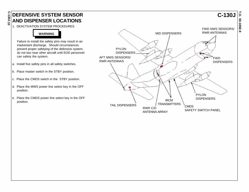
1. DEACTIVATION SYSTEM PROCEDURES
Failure to install the safety pins may result in an inadvertant discharge. Should circumstances prevent proper safetying of the defensive system, do not taxi near other aircraft until EOD personnel can safety the system.
a. Install five safety pins in all safety switches.
b. Place master switch in the STBY position.
c. Place the CMDS switch in the STBY position.
d. Place the MWS power line select key in the OFF position.
e. Place the CMDS power line select key in the OFF position.
10
TAIL DISPENSERS
AFT MWS SENSORS/RWR ANTENNAS
PYLONDISPENSERS
MID DISPENSERSFWD NWS SENSORS/RWR ANTENNAS
FWDDISPENSERS
PYLONDISPENSERS
CMDSSAFETY SWITCH PANEL
IRCMTRANSMITTERS
RWR C/DANTENNA ARRAY
WARNING
DEFENSIVE SYSTEM SENSORAND DISPENSER LOCATIONS

C-130JT.O
. 00-105E-9
C-130J.
CHAFF AND FLARES HAZARDS
WARNING
In case of cartridge separation from the dispensercase, non-essential personnel must withdraw to asafe distance of 300 feet and for markers, 600 feet.On scene authorities determine and evaluate hazards.
11
ELECTRICAL LOCK(SELECT STANDBY)
MECHANICAL LOCK(PUSH TO INSERT)
CHAFF AND FLARESDISPENSER LOCATIONS

C-130JT.O
. 00-105E-9
C-130J.
1
1
1
12
2
34
56
7
8
910
11
11
11
25
2423
2220 19 18
1716 15 14 13 12
2626
21
GENERAL INFORMATION1. FUEL FILLER POINTS (4 PLACES)2. MAIN FUEL TANKS (4 PLACES)3. AUXILIARY FUEL TANKS (2 PLACES)4. CENTER ESCAPE HATCH5. AFT ESCAPE HATCH6. CARGO DOOR7. RAMP8. AUXILIARY HYDRAULIC SYSTEM RESERVOIR9. AUXILIARY HYDRAULIC PUMP10. PARATROOP DOORS (LH SHOWN-RH OPPOSITE)11. ENGINE OIL TANKS (4 PLACES)12. FIRE EXTINGUISHER AGENT BOTTLES13. APU OIL RESERVOIR14. APU15. UTILITY HYDRAULIC SYSTEM RESERVOIR16. ENGINE AIR INTAKE SHIELDS17. SIDE EMERGENCY EXIT (LH SHOWN-RH OPPOSITE)18. CREW ENTRANCE DOOR19. GALLEY20. EXTERNAL ELECTRICAL POWER RECEPTACLE21. BATTERY COMPARTMENT22. EXTERNAL INTERPHONE CONNECTION23. CREW SEATS (3 PLACES)24. FORWARD ESCAPE HATCH25. BOOSTER HYDRAULIC SYSTEM RESERVOIR26. URINALS (2 PLACES)
12
FORWARD CARGOCOMPARTMENT BULKHEAD
HYDRAULICFLUID
MIL-H-83282 H-537
EXTINGUISHERFLUID
ENGINE AND APU MIL-D-4540ALTERNATE MIL-B-4394HAND EXTINGUISHERS MIL-B-3871
OXYGEN MIL-O-27210
SPECIFICATIONSNATO
SYMBOL
FUEL
MIL-T-83133JP-8
MIL-T-5624JP-5JP-4
F-34
F-44F-40
OILENGINE MIL-PRF-23699FAPU MIL-L-7808STARTER
0-1560-148

C-130JT.O
. 00-105E-9
C-130J.
SPECIAL TOOLS/EQUIPMENTPower Rescue SawFire Drill II
AIRCRAFT ENTRY
1. NORMAL ENTRY
NOTE: Use this page and page 14 for entry procedures.
Forward hatch (2a), right side of fuselage, is in close proximity of right inside turbo propeller. Avoid if propeller/engine is running. This hazard could cause loss of life! Not for entry or aircrew extraction until engine is shutdown. Same for left side if applicable model is in use.
CAUTION
Verify aircraft is depressurized prior to entry. If verifica- tion can not be made, use any means possible to penetrate aircraft skin to vent pressure, then enter aircraft. Places to penetrate: entry door, side escape hatches, port hole windows, paratroop doors, emer- gency escape hatches, and designated cut-in areas. Pressurization is 15.6 PSI.
CAUTION
When opening the crew entry door, do allow door to free fall. Damage to door can result hitting the ground surface.
a. Rotate crew entry door handle, located forward left side of fuselage, counterclockwise and open door outward and down.
b. Rotate troop door handle, located aft on both sides of fuselage, clockwise and push door with an inward vertical movement until locked in open position.
13
WARNING
FIRE BOTTLES
SIGNAL FLARES
BATTERY
PYLONTANK1,379 GALS5,220 LITRES
INTERNAL CAPACITY6,750 GALS24,363 LITRES
PYLONTANK1,379 GALS5,220 LITRES
FUEL TANKS
KC-130J-30CARGO COMPARTMENT FUEL TANK (MAX 24,390 LBS)
VIEW LOOKING AFT
C-130JT.O
. 00-105E-9
C-130J.
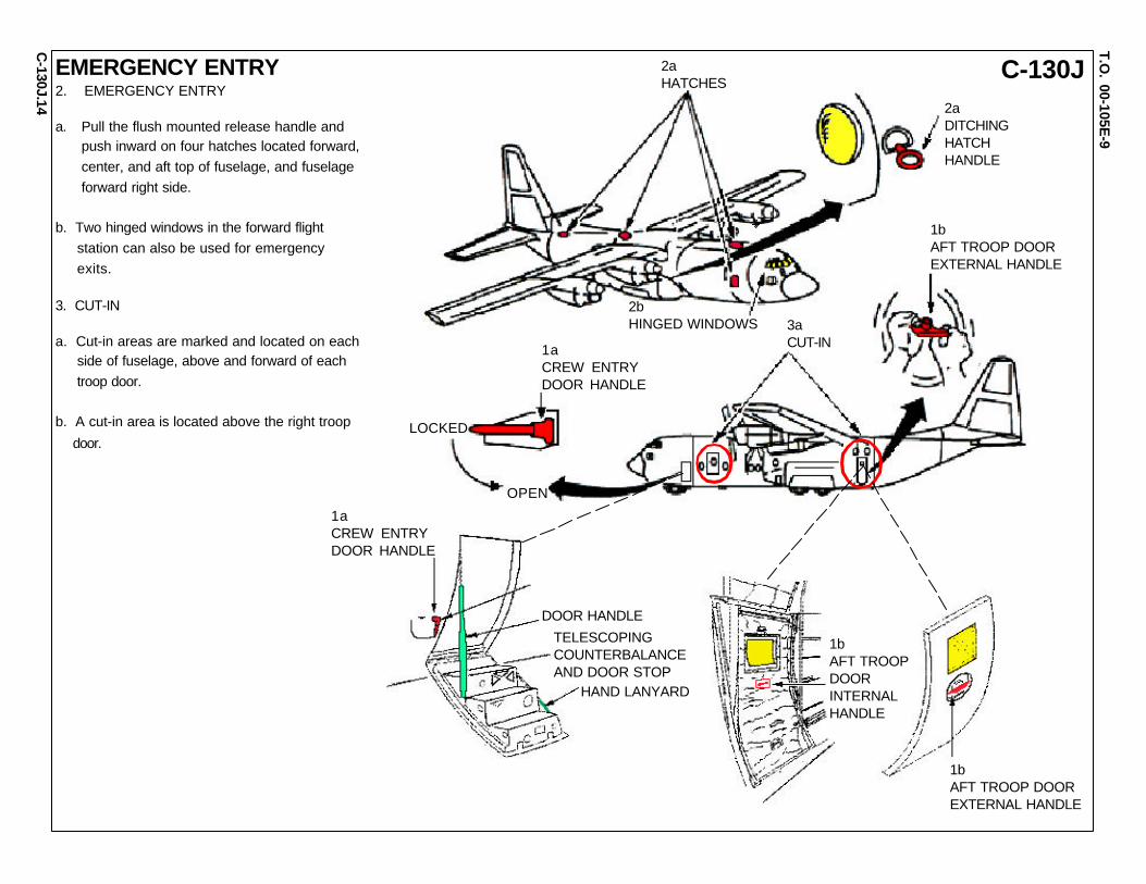
EMERGENCY ENTRY2. EMERGENCY ENTRY
a. Pull the flush mounted release handle and push inward on four hatches located forward, center, and aft top of fuselage, and fuselage forward right side.
b. Two hinged windows in the forward flight station can also be used for emergency exits.
3. CUT-IN
a. Cut-in areas are marked and located on each side of fuselage, above and forward of each troop door.
b. A cut-in area is located above the right troop
door.
2aHATCHES
2aDITCHINGHATCHHANDLE
1bAFT TROOP DOOREXTERNAL HANDLE
1aCREW ENTRYDOOR HANDLE
3aCUT-IN
OPEN
LOCKED
2bHINGED WINDOWS
14
DOOR HANDLE
TELESCOPINGCOUNTERBALANCEAND DOOR STOP
HAND LANYARD
1aCREW ENTRYDOOR HANDLE
1bAFT TROOP DOOREXTERNAL HANDLE
1bAFT TROOPDOORINTERNALHANDLE

C-130JT.O
. 00-105E-9
C-130J.
ENGINE SHUTDOWN AND AIRCREW EXTRACTION
Enter through rear troop doors to avoid running aircraft hazards.
NOTE: DO NOT remove battery power before activating fire T-handles.
1. EMERGENCY ENGINE SHUTDOWN
a. Position the condition levers to the GROUND IDLE position. (There is no FEATHER position on the condition levers.)
CAUTION
Pulling the condition levers all the way backward will cause the engines to go into reverse.
b. On the fire control panel, place the four engine start switches to STOP. (Fuel pump is closed.) Then pull all four fire T-handles OUT position to shut down the engines.
IN CASE OF ENGINE FIRE: After all four fire T-handles have been pulled, turn the appropriate T-handle (fire indication) to position 1 or 2. (Fuel pump is closed.) If fire condition persists, wait 15 seconds after first bottle is discharged and then discharge the remaining bottle.
c. IN CASE OF APU FIRE: Pull the APU fire T-Handle located on the APU control panel.
NOTE: When engines are shutdown, power to internal equipment is shutdown. There is no need to disconnect the battery. If discon- necting the battery, located forward of crew entrance door, is required, removal of the SCBA will be necessary for reaching the battery.
d. Battery switch is located on the overhead electrical panel.
2. AIRCREW EXTRACTION
a. Release latch on lap belt and remove shoulder harness from crewmember(s).
NOTE: If seat track is not damaged during crash landing, use adjustable seat control to move seat in aft position when removing crewmember. Passenger seats do not have shoulder harness.
WARNING15
1aCONDITIONLEVERS
LEFTCONSOLE
RIGHTCONSOLE
LOW SPEED GROUNDIDLE SWITCHES
1dELECTRICAL PANEL
1bFIRE CONTROL PANEL
1cAPU CONTROL PANEL
MASTERCAUTIONSWITCHES
PROPELLERCONTROL PANEL
ENGINE STARTSWITCHES
FIRET-HANDLES
1 2 3 4

C-130JT.O
. 00-105E-9
C-130J.16
OXYGEN SYSTEM AND SHUTDOWN
A
OXYGENREGULATORS
CRYOGENICTRANSPORT VENT
PORTABLE OXYGEN BOTTLE
ARWO OXYGEN REGULATORFLIGHT STATION OXYGEN REGULATOR
OXYGEN SHUTOFF VALVE
OVERHEAD OXYGEN REGULATOR
PILOT OXYGEN REGULATORPORTABLE OXYGEN BOTTLE
RECHARGER HOSEOXYGEN CONVERTER ASSEMBLY
OXYGENOVERBOARDVENT
OXYGEN SERVICING PANEL
PORTABLE OXYGEN BOTTLE
SIGNAL CONDITIONER
RECHARGER HOSE
COPILOT OXYGEN REGULATOR
SYSTEM HEAT EXCHANGERAUGMENTED CREW OXYGEN REGULATOR
RECHARGER HOSE
DSO OXYGENREGULATOR
CARGO COMPARTMENTOXYGEN REGULATOR
FLIGHT STATION OXYGEN REGULATORRECHARGER HOSE
SYSTEM DESCRIPTIONThe oxygen system is a diluter-demand, automatic-pressure breathingsystem with a supply pressure of approximately 270 to 455 PSI. Liquidoxygen is converted to gaseous oxygen for use by the crew. Oxygenregulators are installed in various locations in the flight station and cargocompartment for crew use. Oxygen masks attached to the regulators fitsnugly over the user’s face to eliminate as much leakage as possible.An oxygen servicing panel is located on the exterior of the aircraft.
OXYGEN MANUAL SHUTOFF VALVEA manual shutoff valve is mounted on the right side of the cargo com-partment forward bulkhead above the air conditioning unit. The valve isnormally in the OPEN position. The valve shuts off the liquid oxygensupply prior to the individual regulator distribution lines.
NOTE: The oxygen system supply is carried in a liquid oxygen converter of 25 liters and installed in the NLG wheel well.
FORWARD CARGOCOMPARTMENT BULKHEAD
OXYGENSHUTOFFVALVE
OXYGENSHUTOFFVALVEKNOB
SUPPLYLEVER
PRESSUREGAGE
DILUTERLEVER
FLOWINDICATOR
REGULATORFLOW LEVER A
PORTABLEOXYGENBOTTLE

C-130JT.O
. 00-105E-9
C-130J.
EMERGENCY EXITS & EVACUATION ROUTESFOR GROUND, AIR AND WATER EGRESS
WARNING
Do not lock the augmented crew member seat in aposition that will block the pilot’s evacuation route.
GROUND EXIT
AIR EXIT
EVACUATION ROUTES
OVERHEAD EXIT
CENTER ESCAPE HATCH
AFTESCAPEHATCH
FORWARDESCAPE HATCH
SIDE EMERGENCY EXIT
CARGO DOOR AND RAMP (PRIMARY AIR EXIT)
CREW ENTRANCE DOOR(PRIMARY GROUND EXIT)
HINGEDWINDOWS
SIDEEMERGENCYEXIT
PARATROOP DOORS
17
LIFERAFTCOMPARTMENTS (2)
LIFERAFTCOMPARTMENTS (2)
NOTE:Liferafts are located on both wings. All threeoverhead hatch emergency routes will converge onthese compartments to launch liferafts. The otherexits do not allow this function. The liferaft releaseis just forward of the wing compartments.
LIFERAFTRELEASE
LIFERAFTRELEASE

C-130JT.O
. 00-105E-9
C-130J.
CENTER ESCAPE HATCH LADDER INSTALLATION
18 1. CENTER ESCAPE HATCH LADDER INSTALLATIONa. Remove the ladder from its stowed position on the left side ofthe cargo compartment.
b. Insert the upper ends of the ladder into the A-frame sockets marked “ladder” directly below the escape hatch in the top of the fuselage, just aft of the wing center section. The ladder must be inserted at an angle which will allow its lower end to clear the floor.
c. Push the ladder upward so that the upper ends go through the sockets in the A-frame.
d. Swing the ladder to vertical, and center it over the proper tiedown studs.
e. Lower the ladder until the latches (1) engage the tiedown studs.
1 1

C-130JT.O
. 00-105E-9
C-130J.19
EMERGENCY EQUIPMENT
HAND AXE
SYMBOLS
EMERGENCY EXIT LIGHT
FIRST AID KIT
HAND FREE EXTINGUISHERS
EMERGENCY ESCAPE ROPE
1. HAND FIRE EXTINGUISHER (4)
2. HAND AXE (2)
3. EMERGENCY EXIT LIGHT (8)
4. FIRST AID KIT STOWAGE (22)
5. EMERGENCY TRANSMITTER COMPARTMENT
6. LIFERAFT COMPARTMENT (4)
7. STANCHION LADDER
8. LIFE VEST STOWAGE (10)
9. EMERGENCY ESCAPE ROPE (3)
10. EMERGENCY TIEDOWN FIXTURE (2)
9
3
2
1
4
66
5
10
4
4
3
4
8
8
3
9
12
1
7
9
3
KEY
EFFECTIVITY: C-130J

C-130JT.O
. 00-105E-9
C-130J.20
EMERGENCY EQUIPMENT-Continued
HAND AXE
EMERGENCY EXIT LIGHT
FIRST AID KIT
HAND FREE EXTINGUISHERS
EMERGENCY ESCAPE ROPE
1. HAND FIRE EXTINGUISHER (4)
2. HAND AXE (2)
3. EMERGENCY EXIT LIGHT (8)
4. FIRST AID KIT STOWAGE (28)
5. EMERGENCY TRANSMITTER COMPARTMENT
6. LIFERAFT COMPARTMENT (4)
7. STANCHION LADDER
8. LIFE VEST STOWAGE (10)
9. EMERGENCY ESCAPE ROPE (3)
10. EMERGENCY TIEDOWN FIXTURE (2)
KEY
EFFECTIVITY: CC-130J
9
3
2
1
4
66
510
4
4
3
4
8
3
9
1 2
1
7
9
3
8
SYMBOLS

C-130JT.O
. 00-105E-9
C-130J.
C D E F G H I J K
345 383 472 562 652 742 832 922 1011 1042
92 PARATROOPS 24 INCH (61.0 CM) SEATING
COMPARTMENT DESIGNATIONS
LOAD STATIONS
13 MEN
13 MEN
3 MEN 3 MEN
3 MEN 3 MEN
16 MEN
16 MEN
4 MEN 4 MEN
4 MEN4 MEN
7 MEN
7 MEN
33 MEN33 MEN
128 GROUND TROOPS 20 INCH (50.8 CM) SEATING
LOADMASTER SEATS SAFETY MEN
PERSONNEL LOCATIONS
21 COMPARTMENTSEATING
COMPARTMENT PARATROOPS GROUND TROOPS
C 5 6
D 15 18
E 13 18
F 15 18
G 10 16
H 8 20
I 12 14
J 14 18
NOTE: 1. Number denotes number of litters per tier. 2. * Denotes seat.

C-135.
T.O. 00-105E
-9
C-135AIRCRAFT PAINT SCHEME
1

C-135.
T.O. 00-105E
-9
C-135AIRCRAFT DIMENSIONS
2
LENGTH136.25’ (41.53 M)
HEIGHT41.67’ (12.70 M)
WING SPAN130.83’ (39.88 M)

C-135.
T.O. 00-105E
-9
C-135AIRCRAFT SKIN PENETRATION POINTS
ENGINES - USE FIRE EXTINGUISHER ACCESS PANELS FOR GROUND FIRE ACCESS FUSELAGE - PENETRATE AT THE POINTS
IDENTIFIED FOR EMERGENCY CUT-IN
FOR THE KC-135: PENETRATE THROUGHTHE FIRE EXTINGUISHER ACCESS PANEL
3
CAPACITIES:C-135 - 26 TROOPS, 44 STRETCHERSKC-135 - 2 PILOTS, 2 CREW, 80 PASSENGERSOC-135 - 3 PILOTS, 2 NAVIGATORS, 1 MISSION CMDR, 1 DEPUTY MISSION CMDR, 2 SENSOR OPERATORS, 2 SENSOR MAINTENANCE TECHNICIANS, 1 FLIGHT FOLLOWERRC-135 - 3 PILOTS, 2 NAVIGATORS, 3 ELECTRONIC WAREFARE OFFICERS, 14 INTELLIGENCE OPERATORS, 4 MAINTENANCE TECHNICIANSRC-135 - 31 PEOPLE; 10 FWD, 21 AFTEC-135 - 26 PEOPLE; 4 FWD, 22 AFT
Effectivity: KC-135 only. Forward right side fuselage penetration points do notapply. On KC-135 aeromedical evacuation missions, the right side of the fuse-lage from body stations 440-840 is occupied by patients, patient litters, medicalpersonnel, and medical equipment to include medical oxygen storage systems.(The painted penetration symbol are being removed.)
WARNING

C-135.
T.O. 00-105E
-9
C-135SPECIAL TOOLS/EQUIPMENTPower Rescue Saw24 Ft. LadderFire Drill IIAIRCRAFT ENTRY1. NORMAL ENTRY
a. Press latch, located aft of crew entry door. To open access door, rotate handle down to release door.
CAUTION
Door opens down and forward.
2. EMERGENCY ENTRY
a. Depress button(s), located on emergency escape hatch(es),over wing both sides of aircraft, to release handle(s). Pullhandle(s) out and rotate clockwise to release hatch(es).
b. Push emergency escape hatch(es) in.
c. Depress button, located on aft emergency escape hatch,right side of aircraft, to release handle. Pull handle out androtate clockwise to release hatch. Push hatch in and aft.
3. CUT-IN
a. Cut-in areas as marked on fuselage.
CAUTION
For special purpose C-135 aircraft, the lack of indicated skin penetration points in these areas may indicate the presence of interior equipment preventing emergency access.
NOTE: Aircraft Gear Up - 13 ft 10 in. Gear Down - 17 ft 10 in.
NOTE: The battery is located in the forward latrine, in front of the cargo door. Some aircraft have outward opening latrine doors.
4
NOTE: Oxygen capacity is doubled from six (6) to twelve (12) cylinders on A, D, E, Q and R models.
OXYGENCYLINDERS
OXYGENCONVERTERS
FUEL TANKS
FUEL TANK WITHOUT UPPERTANK DECK INSTALLED. (5807)WITH UPPER TANK INSTALLED.
OXYGENCONVERTER
BATTERY
2cAFT EMERGENCYESCAPE HATCH
2aRELEASE HANDLEWITH BUTTON
2bEMERGENCYESCAPE HATCH
NO OUTSIDEACCESS(ALL MODELS)
1aCREW ENTRYDOOR
RC-SOMEBLOCKEDEC-NOTBLOCKED
NOTE:On EC-15C aircraft, theSF-6 bottle is locatedinside the fuselageimmediately in front ofthe right overwingescape hatch.

C-135.
T.O. 00-105E
-9
C-135
5
ENGINE SHUTDOWN, AIRCREW EXTRACTIONAND CARGO DOOR OPERATION1. ENGINE SHUTDOWN [KD] [KE]
a. Aircraft without thrust reversers, retard throttles, located oncontrol stand, to IDLE position then raise throttles and bringback to CUT-OFF position.
b. KC-135D/E with thrust reversers, place throttles to IDLEposition, place engine start levers, located on lower portion ofcontrol stand, to CUTOFF position.
c. To extinguish an engine fire: pull the applicable engine fireswitch, located above pilots center instrument panel, to theaffected engine.
d. Place battery switch, located on pilot’s center instrumentpanel, to OFF position.
2. AIRCREW EXTRACTION (ALL MODELS)
a. Unlatch lap belt and remove shoulder harness fromcrewmember(s).
b. If seat tracks are not damaged, use adjustable seat control to retract seat in aft position to aid in removing crewmember(s).c. Unlatch lap belts for passengers.
3. OPERATION OF CARGO DOOR IS NEEDED DURING RESCUE (ALL MODELS)
a. Press pressure valve pedals outward.b. Rotate handles inboard and downward.c. Rotate position selector valve to OPEN positiond. Use hand pump to pump door open.
1aTHROTTLES
3bHANDLES
3dHAND PUMP
1aTHROTTLES
1bENGINETHROTTLELEVERS
3cPOSITIONSELECTORVALVE
3aPRESSURE VALVE PEDALS
1cENGINE FIRE T-HANDLES
1dBATTERYSWITCH
GLARESHIELD

C-135.
T.O. 00-105E
-9
C-135ENGINE AND APU SHUTDOWNFOR THE KC-135R6
1. ENGINE SHUTDOWN [KR] [KT]
a. Retard throttles, located on center control stand, to IDLE position, then raise throttles and move aft to CUTOFF position.
b. Place the battery switch, located on the pilot’s console, in the EMERGENCY position.
NOTE: Use ENGINE FIRE/OVERHEAT DETECTION AND EXTINGUISHING SYSTEM only if an engine fire is indicated.
c. To extinguish an engine fire:
(1) Pull the applicable engine fire switch, located above pilot’s center instrument panel, to the affected engine.
NOTE: On some models, the engine fire switches may be rotated vertically.
(2) Press the applicable engine EXT switch, located directly above the engine fire switches, to the affected engine.
2. APU SHUTDOWN (KC-135R)
a. Place APU 1 and APU 2 switches, located on the instrument panel, to STOP position.
(Procedures continue on next page.)
1c(2)FIREEXTINGUISHERSWITCHES
1c(1)FIRE PULLSWITCHES
2aAPU SWITCHES
1aTHROTTLES
GLARESHIELD
1bBATTERYSWITCH

C-135.
T.O. 00-105E
-9
C-135ENGINE AND APU SHUTDOWNFOR THE KC-135R-Continued2. APU SHUTDOWN (KC-135R) -Continued
NOTE: The APU’s may be shutdown from the aft control panel, located directly opposite the aft emergency exit.
b. Place APU 1 and APU 2 switches to STOP position.
c. For emergency shutdown, push APU 1 and APU 2 EMERG STOP buttons, located directly beneath APU normal operation switches.
d. Place battery switch, located on pilot’s instrument panel, to OFF position.
7
2dBATTERYSWITCH
APU
2bAPUSWITCHES
2cEMERGENCY STOP BUTTONS
APU AFTCONTROLPANEL
PILOT’S INSTRUMENT PANEL

C-135.
T.O. 00-105E
-9
C-1351. APU SHUTDOWN (KC-135D/E)
NOTE: Procedures apply to all four stations (1) Crew entry door (2) Navigator’s control panel (3) Pilot’s control panel and (4) APU junction box. Placing any one of the four emergency stop switches to the stop position will shutdown the APU. Electrical power to the fuel pump and the fuel shutoff valve will be shutoff. The fuel valve will close when electrical power is off.
a. Lift guard on emergency stop switch.
b. Place emergency stop switch to STOP.
2. MANUAL DISCHARGE OF APU FIRE BOTTLE
NOTE: APU battery switch must be on.
a. At the navigator’s APU control panel, place the emer- gency stop switch to the STOP position.
b. Place the fire discharge switch to the FIRE position to discharge the APU fire bottle.
(1) CREW ENTRY DOOR
1a, 1bEMERGENCY STOPGUARD AND SWITCH
(2) NAVIGATOR’S CONTROL PANEL
1a, 1bEMERGENCYSTOPGUARDAND SWITCH
2aFIREDISCHARGESWITCH
1a, 1bEMERGENCYSTOP GUARDAND SWITCH
(3) PILOT’S CON-TROL PANEL
1a, 1bEMERGENCYSTOP GUARDAND SWITCH
(4) APU JUNCTION BOX
8
APU SHUTDOWN FOR SELECTED KC-135D/E

C-135.
T.O. 00-105E
-9
C-135APU SHUTDOWN FOR SELECTED KC-135D/E-Continued
9 3. STOPPING THE AiRearch APU
a. Place the primer switch, located on the AiRearch APU control panel, to the OFF position.
b. Set the start - stop switch, located on the AiRearch APU control panel, momentarily to the STOP position.
c. Place the master switch, located on the AiRearch APU control panel, to the OFF position.
4. STOPPING THE SOLAR APU
a. Place the power switch, located on the Solar APU control panel, to the OFF position.
3aMASTER SWITCH 3b
PRIMER SWITCH
3cSTART - STOP SWITCH
AIRESEARCH APUCONTOL PANEL
SOLAR APUCONTOL PANEL
4aPOWER SWITCH
C-135.
T.O. 00-105E
-9
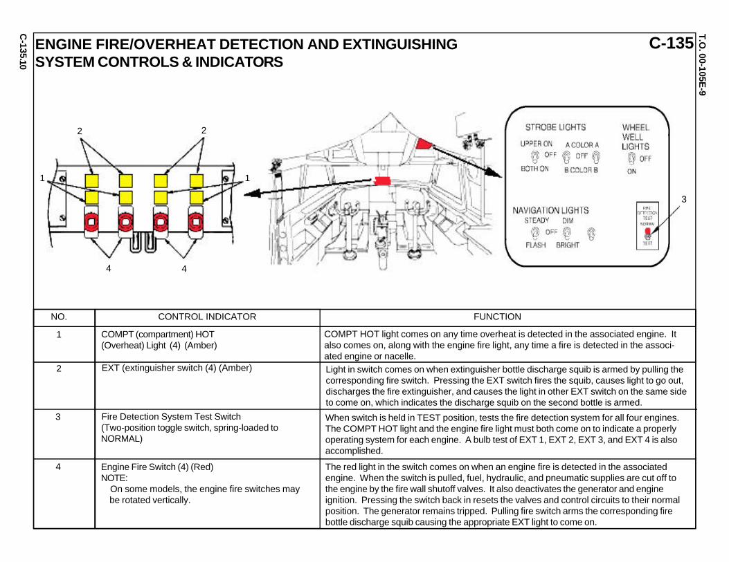
C-135ENGINE FIRE/OVERHEAT DETECTION AND EXTINGUISHINGSYSTEM CONTROLS & INDICATORS
NO. CONTROL INDICATOR FUNCTION
COMPT (compartment) HOT(Overheat) Light (4) (Amber)
1
EXT (extinguisher switch (4) (Amber)2
Fire Detection System Test Switch (Two-position toggle switch, spring-loaded to NORMAL)
4
3
Engine Fire Switch (4) (Red)NOTE: On some models, the engine fire switches may be rotated vertically.
COMPT HOT light comes on any time overheat is detected in the associated engine. Italso comes on, along with the engine fire light, any time a fire is detected in the associ-ated engine or nacelle.Light in switch comes on when extinguisher bottle discharge squib is armed by pulling thecorresponding fire switch. Pressing the EXT switch fires the squib, causes light to go out,discharges the fire extinguisher, and causes the light in other EXT switch on the same sideto come on, which indicates the discharge squib on the second bottle is armed.
When switch is held in TEST position, tests the fire detection system for all four engines.The COMPT HOT light and the engine fire light must both come on to indicate a properlyoperating system for each engine. A bulb test of EXT 1, EXT 2, EXT 3, and EXT 4 is alsoaccomplished.
The red light in the switch comes on when an engine fire is detected in the associatedengine. When the switch is pulled, fuel, hydraulic, and pneumatic supplies are cut off tothe engine by the fire wall shutoff valves. It also deactivates the generator and engineignition. Pressing the switch back in resets the valves and control circuits to their normalposition. The generator remains tripped. Pulling fire switch arms the corresponding firebottle discharge squib causing the appropriate EXT light to come on.
10
4 4
22
1 1
3

C-135.
T.O. 00-105E
-9
C-135
11
MULTIPOINT REFUELING SYSTEMFOR THE KC-135RGENERAL INFORMATIONThe system incorporates the proven FlightRefueling Limited (FRL) MK-32B refueling pod.It provides offload capability of 400 gallons perminute (independent or simultaneous). There ispod interchangeability. The self contained podsare located just inside and under the wing tips.The system provides interservice operability forthe Air Force, Navy, Marines, and NATO. Itprovides capability for simultaneous refueling oftwo probed equipped receivers.
Fuel to receiver aircraft is transferred from the aftbody fuel tank. Fuel vents are modified to allowadditional passage of fuel in the event of a manifoldcoupling failure. There are four fuel vent relief doorsin each wing. Pods are controlled from Boom Station.Pods are illuminated by outside engine nacelle lights.
MPRS Pod CharacteristicsLength: 173 inchesDiameter: 34 inchesHose Length: 78 feet, +4, -0 inchesDrogue Diameter (deployed): 24.8 inchesWet Weight: 1,351 lbsDry Weight: 1,199 lbsVoltages: 5V ac, 28V dc
115V ac, 400Hz, single phase 115V ac, 400Hz, three phaseHose Pressure: 50+/- 5 psig
POD/PYLON ARRANGEMENTThe pod uses a digital electronic system to controlmechanical functions, electro-fueldraulic functionsfor fuel pressure, fuel flow, venting, fuel transfer,trailing, and winding. Digital electronic system hasbuilt-in test equipment (BITE) for ground maintenanceand pre-flight and in-flight checks.
RAM AIRTURBINE
RAT SPEEDSENSOR
RAT MOTORASSEMBLY
FCV MOTORDRIVE UNIT
BLEED LINE
HOT FUELSPILL VALVE
TO ACFTFUEL VENT
FROM ACFTFUEL SUPPLY
TENSATOR MOTOR UNIT
TENSATORTORQUEDRUM UNIT
FULL TRAILBRAKE
TENSATORSECONDARYDRIVE CHAIN
SLIP RINGASSEMBLY
TENSATORDRIVEUNIT
SERVINGCARRIAGE
HOSEPOSITIONSENSOR
BUFFERSPRING
RECEPTIONCOUPLING
DROGUEASSEMBLY
FUELVENT
RATSPEEDSENSOR
INLETPRESSURETRANSDUCER
DIGITALREFUELINGCONTROLUNIT FUEL
CONTROLVALVE (FCV)
SNUBBINGVALVE
VANEPUMP
JOCKEY WHEELADJUSTER
TRAILBRAKEGEARBOX
PARKINGBRAKELINEARACTUATOR
JOCKEYWHEEL ADJUSTER
POWERSUPPLYUNIT
HOSERELEASESOLENOID
TENSATOR PRIMARYDRIVE CHAIN
REARFAIRING
SERVINGCARRIAGEDRIVE CHAIN
JOCKEYWHEELADJUSTER HOSE DRUM
ASSEMBLY
FUELTRANSFERFUELVALVE
FILTER BOX ASSEMBLYPOWER LINE FILTER
BLEEDLINE
SURGE SUPPRESSORTHERMAL RELIEF VALVE
RAT MOTOR DRIVE UNITFUELFLOW-METER
FRONTFAIRING
FCV MOTOR ASSEMBLY
AMBIENT PRESSURESENSOR
FCV POTENTIOMETER SENSOR
FUEL DOOR
WINDINGHANDLE DOOR
OUTLET PRESSURE TRANSDUCER
HOSEDRUMDRIVE UNITGEARBOX
CHAINADJUSTER
ELAPSED HOURS COUNTER
HOSEDRUMDRIVECHAIN
HOSEDRUMDOOR
RIGHTSIDEDOOR
HOSE
MK 32B-753 POD RIGHT SIDE
MK 32B-753 POD LEFT SIDE

C-135.
T.O. 00-105E
-9
C-135MULTIPOINT REFUELING SYSTEMFOR THE KC-135R-ContinuedPOD CUT-AWAY AND STRUCTURE COMPONENTS
1. COMPONENTS:a. Basic structure that forms primary skeleton elementb. Hinged nose fairing assemblyc. Fuel door assemblyd. Left gull-wing side-door assemblye. Right gull-wing side-door assemblyf. Hose drum door assemblyg. Rear fairing assemblyh. Winding handle door assemblyi. Chine blades
12
1eRIGHT GULLWING DOOR
1dLEFT GULLWING DOOR
1iAFT CHINE BLADE(LH POD ONLY)
1gREARFAIRING
1iFORWARD CHINEBLADE (LH PODONLY)
1hWINDING HANDLEACCESS DOOR
1bHINGED NOSE FAIRING 1c
FUEL DOOR
1fHOSE DRUM DOOR
1aCUT AWAY SHOWINGSHELETAL ELEMENTS
LOCATIONS FOR RIGHT AND LEFTMK-32B REFUELING PODS
C-135.
T.O. 00-105E
-9
C-135
13
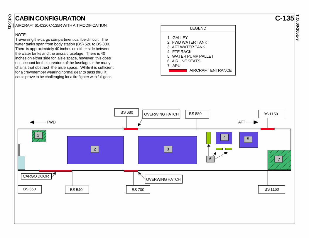
CABIN CONFIGURATIONAIRCRAFT 61-0320 C-135R WITH AIT MODIFICATION
NOTE:Traversing the cargo compartment can be difficult. Thewater tanks span from body station (BS) 520 to BS 880.There is approximately 40 inches on either side betweenthe water tanks and the aircraft fuselage. There is 40inches on either side for aisle space, however, this doesnot account for the curvature of the fuselage or the manychains that obstruct the aisle space. While it is sufficientfor a crewmember wearing normal gear to pass thru, itcould prove to be challenging for a firefighter with full gear.
LEGEND
1. GALLEY2. FWD WATER TANK3. AFT WATER TANK4. FTE RACK5. WATER PUMP PALLET6. AIRLINE SEATS7. APU AIRCRAFT ENTRANCE
OVERWING HATCH
OVERWING HATCHCARGO DOOR
FWD
BS 360 BS 540 BS 700
BS 680 BS 880 BS 1150
BS 1160
1
2 3
6
4 5
7
AFT

NC
-135W.
NC-135WT.O
. 00-105E-9
TEST BED AIRCRAFT
1
1. PASSENGER CAPACITY: 34
2. OXYGEN SYSTEM:
a. There are 36 portable oxygen bottles. There are four onthe flight deck; two behind the pilot’s seat, one behindthe copilot’s seat, and one under the aux crew seat. Onthe LH side; there are two at FS 820, four at FS 860,three at FS 1010, one at FS 1110, one at FS 1160, twoat FS 1210, three at FS 1240, and two at FS 1260. Onthe RH side; there are two at FS 540, two at FS 650,three at FS 670, two at FS1060, two at FS 1190, andthree at FS 1230. b. There are two Liquid Oxygen (LOX)converters installed at FS 1340. One converter is locatedin the aft LH latrine area and one is located in the aft RHlatrine area.
3. MODIFIED ESCAPE ROUTES: None.
4. CHANGES IN ELECTRICAL/BATTERY POWER:a. Generators are installed on engines 1, 2, and 4. They are 40 kVA constant-speed drive generators.
b. The DC voltage is supplied by two transformer-rectifiers (TR). TR1 and TR2 supply DC voltage to the basic aircraft.
c. Two aircraft batteries are located on the flight deck at the bottom of the Electrical Rack (LH FS 340).
d. There are two circuit breaker panels in the crew compart- ment for distributing power to electronic equipment; one at FS 600 and one at FS 1160. Each has a power switch for applying/removing power to supported elec- tronic equipment. See illustration.
GROUND LINE REF
NOTE: This aircraft is a test bed. This illustration shows the normal configuration. Actual configuration may vary based on test requirements.

NC
-135W.
NC-135WT.O
. 00-105E-9
TEST BED AIRCRAFT-Continued
2
FUEL TANKS AND CAPACITIES(IN US GALLONS)
5. HINDRANCES: Special and electronic equipment existson the right side from FS 540 to FS 650. Special andelectronic equipment exists on the left side from FS 710to FS 820; from FS 860 to FS 990; and from FS 1110 toFS 1160.
6. NORMAL/MANUAL/EMERGENCY ENTRY:
a. Normal Entry: Use crew entry door beneath the flightdeck on the LH side of the aircraft. The outer door latchhandle is located behind the access panel at the aft edgeof the door. Pull handle firmly to release door.
CAUTION
Door opens down and forward.
b. The cargo door can only be opened from the inside.When aircraft power is available, the cargo door is oper-ated by electrically controlled hydraulic pump. When nopower is available, the pump must be manually operated.
c. Emergency Exits: There are five emergency exits: pilot’ssliding window, co-pilot’s sliding window, LH side and RHside over-wing hatches at FS 700, and the aft RH sidehatch at FS 1160.
NOTE:Escape ropes are installed above pilot and co-pilotsliding windows, as well as above the aft hatch.
d. Skin Penetration Points: There are skin penetrationpoints on the RH side at approximately FS 450, FS 800,and FS 1220.

NC
-135W.
NC-135WT.O
. 00-105E-9
TEST BED AIRCRAFT-Continued
3
7. ENGINE SHUTDOWN: The location and position of engine throttle levers, fuel selector switches/levers, master and battery switch, engine fire shutdown switches and T-handles are the same as the C-135.
8. AIRCREW EXTRACTION:a. Crew seat controls and adjustments: (1) Armrest adjustment is located below the front part of the armrest and controls the downward position of the armrest.
(2) Seat forward/backward movement is controlled by the front handle on either side of the pilot and copilot seats. The forward/backward movement of operator seats is con- trolled by lifting rod under the seat, then sliding seat in desired direction.
(3) The operator seats can be rotated 360 degrees using right front handle below the seat.
b. Pilot, copilot, and operator seat restraint belt release is lo- cated at the central harness connection point. To release the restraints, facing the crewmember, turn the center part of the connection counter-clockwise.
c. Crew rest and observer seats have lap belts only.
9. SURVIVAL EQUIPMENT:a. Two 20-man life rafts are stowed at FS 650 on LH and RH sides of the aircraft.
b. The aircraft has three emergency equipment panels: one above the crew entry chute, one at FS 530 (RH), and one at FS 1250 (LH). Emergency equipment panels may include a crash axe, first aid kit(s), fire-fighters mask, and Halon fire extinguisher(s).
PILOT/COPILOT SEAT
OPERATOR SEAT
8b
8a(1)
8a(1) 8a(2)
8a(2)
8b
8a(3)
8a(1)
8a(1)

RC
-135S.
RC-135ST.O
. 00-105E-9
1
GROUND LINE REF
RC-135S, TYPICAL PROFILE, LOCATION OF ELECTRICAL PANELS
4d DENOTES PANEL LOCATIONS
1. PASSENGER CAPACITY: 28
2. OXYGEN SYSTEM:
a. There are 31 portable oxygen bottles. There are four on the flight deck; two behind the pilot’s seat, and two behind aux crew seat. On the LH side there are two at FS 360. On the RH side, there are three at FS 640; three at FS 660, two at FS 800; two at FS 880; two at FS 950; two at FS 1020, three at FS 1060, three at FS 1100, three at FS 1125, and two at FS 1190.
b. There are three Liquid Oxygen (LOX) converters between FS 1280 and FS 1340 in the lower baggage compartment.
3. MODIFIED ESCAPE ROUTES: None.
4. CHANGES IN ELECTRICAL/BATTERY POWER:
a. Generators are installed on engines 1, 2, and 4. They are 75/90 kVA constant-speed drive generators.
b. The DC voltage is supplied by four 200-amp transformer- rectifiers (TR). TR1 and TR2 supply DC voltage to the basic aircraft. TR3 and TR4 supply DC voltage to the special equipment in the cargo compartment.
c. Two aircraft batteries are located on the flight deck at the bottom of the Electrical Rack (LH side).
d. There are additional circuit breaker panels throughout the cargo compartment to protect the special and electronic equipment. See illustration.
COBRA BALL

RC
-135S.
RC-135ST.O
. 00-105E-9
2
5. HINDRANCES: Special and electronic equipment exists on the right side from FS 420 to FS 550; from FS 710 to FS 1020; and from FS 1180 to FS 1340. On the left side, equipment exists from FS 580 to FS 680; from FS 720 to FS 1240; and from FS 1270 to FS 1400.
6. NORMAL/MANUAL/EMERGENCY ENTRY:
a. Normal Entry: Use crew entry door beneath the flight deck on the LH side of the aircraft. The outer door latch handle is located behind the access panel at the aft edge of the door. Pull handle firmly to release door.
CAUTION
Door opens down and forward.
b. The cargo door can only be opened from the inside. When aircraft power is available, the cargo door is operated by electrically controlled hydraulic pump. When no power is available, the pump must be manually operated.
c. Emergency Exits: There are five emergency exits: pilot’s sliding window, co-pilot’s sliding window, LH side and RH side over-wing hatches at FS 700, and the aft RH side hatch at FS 1160.
NOTE: Escape ropes are installed above pilot and co-pilot sliding windows, as well as above the aft hatch.
d. Skin Penetration Points: There are skin penetration points located on the RH side at approximately FS 650 and FS 1090 and on the LH side at approximately FS 1110.
FUEL TANKS AND CAPACITIES(IN US GALLONS)
ACFT 62-4128ACFT 62-2662ACFT 62-2663
COBRA BALL-Continued

RC
-135S.
RC-135ST.O
. 00-105E-9
3
7. ENGINE SHUTDOWN: The location and position of engine throttle levers, fuel selector switches/levers, master and battery switch, engine fire shutdown switches and T-handles are the same as the C-135.
8. AIRCREW EXTRACTION:a. Crew seat controls and adjustments: (1) Armrest adjustment is located below the front part of the armrest and controls the downward position of the armrest.
(2) Seat forward/backward movement is controlled by the front handle on either side of the pilot and copilot seats. The forward/backward movement of operator seats is con- trolled by lifting rod under the seat, then sliding seat in desired direction.
(3) The operator seats can be rotated 360 degrees using right front handle below the seat.
b. Pilot, copilot, and operator seat restraint belt release is lo- cated at the central harness connection point. To release the restraints, facing the crewmember, turn the center part of the connection counter-clockwise.
c. Crew rest and observer seats have lap belts only.
9. SURVIVAL EQUIPMENT:a. A 20-man life rafts are stowed at FS 640 and FS 680 on left side under the Comms Rack.
b. The aircraft has four emergency equipment panels: one above the crew entry chute, one at FS 650 (LH); one at FS 720 (RH), and at FS 1190 (RH). Emergency equipment panels may include a crash axe, first aid kit(s), fire-fighters mask, and Halon fire extinguisher(s).
PILOT/COPILOT SEAT
OPERATOR SEAT
8b
8a(1)
8a(1) 8a(2)
8a(2)
8b
8a(3)
8a(1)
COBRA BALL-Continued
8a(1)
RC
-135U.
RC-135UT.O
. 00-105E-9
1
GROUND LINEREF
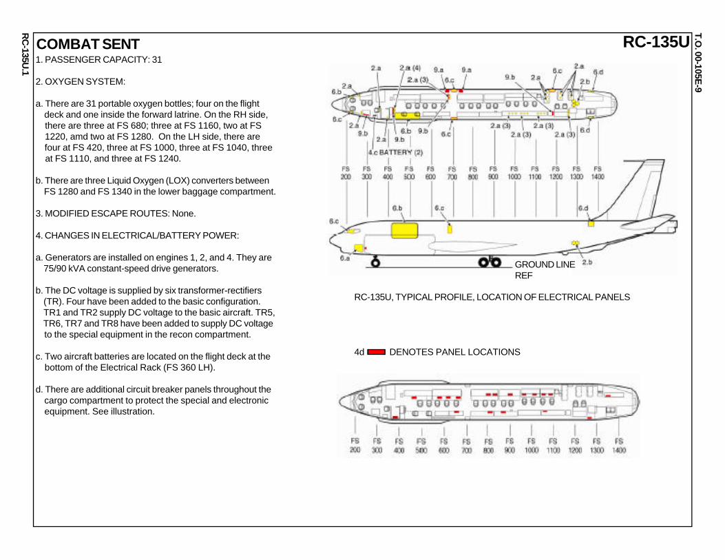
RC-135U, TYPICAL PROFILE, LOCATION OF ELECTRICAL PANELS
4d DENOTES PANEL LOCATIONS
1. PASSENGER CAPACITY: 31
2. OXYGEN SYSTEM:
a. There are 31 portable oxygen bottles; four on the flight deck and one inside the forward latrine. On the RH side, there are three at FS 680; three at FS 1160, two at FS 1220, amd two at FS 1280. On the LH side, there are four at FS 420, three at FS 1000, three at FS 1040, three at FS 1110, and three at FS 1240.
b. There are three Liquid Oxygen (LOX) converters between FS 1280 and FS 1340 in the lower baggage compartment.
3. MODIFIED ESCAPE ROUTES: None.
4. CHANGES IN ELECTRICAL/BATTERY POWER:
a. Generators are installed on engines 1, 2, and 4. They are 75/90 kVA constant-speed drive generators.
b. The DC voltage is supplied by six transformer-rectifiers (TR). Four have been added to the basic configuration. TR1 and TR2 supply DC voltage to the basic aircraft. TR5, TR6, TR7 and TR8 have been added to supply DC voltage to the special equipment in the recon compartment.
c. Two aircraft batteries are located on the flight deck at the bottom of the Electrical Rack (FS 360 LH).
d. There are additional circuit breaker panels throughout the cargo compartment to protect the special and electronic equipment. See illustration.
COMBAT SENT

RC
-135U.
RC-135UT.O
. 00-105E-9
2
5. HINDRANCES: Special and electronic equipment exists on the right side from FS 400 to FS 660, from FS 720 to FS 1100, and from FS 1280 to FS 1380. On the LH side, special and electronic equipment exists from FS 560 to FS 660, from FS 715 to FS 1240, and from FS 1260 to FS 1350.
6. NORMAL/MANUAL/EMERGENCY ENTRY:
a. Normal Entry: Use crew entry door beneath the flight deck on the LH side of the aircraft. The outer door latch handle is located behind the access panel at the aft edge of the door. Pull handle firmly to release door.
CAUTION
Door opens down and forward.
b. The cargo door can only be opened from the inside. When aircraft power is available, the cargo door is operated by electrically controlled hydraulic pump. When no power is available, the pump must be manually operated.
c. Emergency Exits: There are five emergency exits: pilot’s sliding window, co-pilot’s sliding window, LH side and RH side over-wing hatches at FS 700, and the aft RH side hatch at FS 1160.
NOTE: Escape ropes are installed above pilot and co-pilot sliding windows and above the aft hatch.
d. Skin Penetration Points: There are skin penetration points located at approximately FS 1400 WL 265 on both sides of the aircraft.
FUEL TANKS AND CAPACITIES(IN US GALLONS)
COBRA BALL-Continued

RC
-135U.
RC-135UT.O
. 00-105E-9
3
7. ENGINE SHUTDOWN: The location and position of engine throttle levers, fuel selector switches/levers, master and battery switch, engine fire shutdown switches and T-handles are the same as the C-135.
8. AIRCREW EXTRACTION:a. Crew seat controls and adjustments: (1) Armrest adjustment is located below the front part of the armrest and controls the downward position of the armrest.
(2) Seat forward/backward movement is controlled by the front handle on either side of the pilot and copilot seats. The forward/backward movement of operator seats is con- trolled by lifting rod under the seat, then sliding seat in desired direction.
(3) The operator seats can be rotated 360 degrees using right front handle below the seat.
b. Pilot, copilot, and operator seat restraint belt release is lo- cated at the central harness connection point. To release the restraints, facing the crewmember, turn the center part of the connection counter-clockwise.
c. Troop, crew rest and observer seats have lap belts only.
9. SURVIVAL EQUIPMENT:a. Two 20-man life rafts are stowed on the floor, one forward and one aft of the RH over wing hatch.
b. The aircraft has three emergency equipment panels: one above the crew entry chute, one at FS 420 (LH); one at FS 1190. Emergency equipment panels may include a crash axe, first aid kit(s), fire-fighters mask, and Halon fire extinguisher(s).
PILOT/COPILOT SEAT
OPERATOR SEAT
8b
8a(1)
8a(1)
8a(2)
8a(2)
8b
8a(3)
8a(1)
COBRA BALL-Continued
8a(1)

RC
-135V/W
.
RC-135V/WT.O
. 00-105E-91
GROUND LINEREF
RC-135V/W, TYPICAL PROFILE, LOCATION OF ELECTRICAL PANELS
4d DENOTES PANEL LOCATIONS
RIVET JOINT1. PASSENGER CAPACITY: 39
2. OXYGEN SYSTEM:
a. There are 37 portable oxygen bottles. There are four on the flight deck; two behind the pilot’s seat, one behind the copilot’s seat, and one under the aux crew seat. On the RH side, one is located at FS 500, there are two at FS 610, two at FS 745, two at FS 825, two at FS 895, two at FS 960, two at FS 1020, three at FS 1140, and two at FS 1220. On the LH side, there are four at FS 540, two at FS 1095, two at FS 1110, two at FS 1150, two at FS 1190, two at FS 1230, and one at FS 1340.
b. There are three Liquid Oxygen (LOX) converters between FS 1280 and FS 1340 in the lower baggage compartment.
3. MODIFIED ESCAPE ROUTES: The RH over-wing hatch is blocked by equipment.
4. CHANGES IN ELECTRICAL/BATTERY POWER:
a. Generators are installed on engines 1, 2, and 4. They are 75/90 kVA constant-speed drive generators.
b. The DC voltage is supplied by seven transformer-rectifiers (TR). Four 100-amp TRs; TR1, TR2, TR3, and TR4 supply DC voltage to the basic aircraft. Three 200-amp TRs; TR5, TR6, and TR7 supply DC voltage to the special equipment in the recon compartment.
c. Two aircraft batteries are located on the flight deck at the bottom of the Electrical Rack (FS 360 LH).
d. There are additional circuit breaker panels throughout the cargo compartment to protect the special and electronic equipment. See illustration.

RC
-135V/W
.
RC-135V/WT.O
. 00-105E-92
FUEL TANKS AND CAPACITIES(IN US GALLONS)
RIVET JOINT-Continued5. HINDRANCES: Special and electronic equipment exists on the RH side from FS 400 to FS 1360. Special and electronic equipment exists on the LH side from FS 545 to FS 680, from FS 757 to FS 1224, and from FS 1269 to FS 1400.
6. NORMAL/MANUAL/EMERGENCY ENTRY:
a. Normal Entry: Use crew entry door beneath the flight deck on the LH side of the aircraft. The outer door latch handle is located behind the access panel at the aft edge of the door. Pull handle firmly to release door.
CAUTION
Door opens down and forward.
b. The cargo door can only be opened from the inside. When aircraft power is available, the cargo door is operated by electrically controlled hydraulic pump. When no power is available, the pump must be manually operated.
c. Emergency Exits: There are four emergency exits: pilot’s sliding window, co-pilot’s sliding window, LH over-wing hatch at FS 700, and the aft RH hatch at FS 1160. The RH over-wing hatch is blocked.
NOTE: Escape ropes are installed above pilot and co-pilot sliding windows, as well as above the aft hatch.
d. Skin Penetration Points: There are no skin penetration points due to the location of mission equipment.

RC
-135V/W
.
RC-135V/WT.O
. 00-105E-93
7. ENGINE SHUTDOWN: The location and position of engine throttle levers, fuel selector switches/levers, master and battery switch, engine fire shutdown switches and T-handles are the same as the C-135.
8. AIRCREW EXTRACTION:a. Crew seat controls and adjustments: (1) Armrest adjustment is located below the front part of the armrest and controls the downward position of the armrest.
(2) Seat forward/backward movement is controlled by the front handle on either side of the pilot and copilot seats. The forward/backward movement of operator seats is con- trolled by lifting rod under the seat, then sliding seat in desired direction.
(3) The operator seats can be rotated 360 degrees using right front handle below the seat.
b. Pilot, copilot, and operator seat restraint belt release is lo- cated at the central harness connection point. To release the restraints, facing the crewmember, turn the center part of the connection counter-clockwise.
c. Crew rest and observer seats have lap belts only.
9. SURVIVAL EQUIPMENT:a. Two 20-man life rafts are stowed on the left side of the aircraft between FS 614 and FS 688.
b. The aircraft has three emergency equipment panels: one above the crew entry chute, one at FS 620 (LH); one at FS 620 (LH) and one at FS 1290 (LH). Emergency equip- ment panels may include a crash axe, first aid kit(s), fire- fighters mask, and Halon fire extinguisher(s).
PILOT/COPILOT SEAT
OPERATOR SEAT
8b
8a(1)
8a(1) 8a(2)
8a(2)
8b
8a(3)
8a(1)
RIVET JOINT-Continued
8a(1)
TC-135S
.
TC-135ST.O
. 00-105E-9
1
GROUND LINE REF
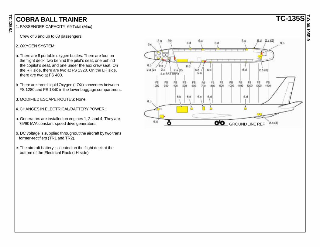
COBRA BALL TRAINER1. PASSENGER CAPACITY: 69 Total (Max)
Crew of 6 and up to 63 passengers.
2. OXYGEN SYSTEM:
a. There are 8 portable oxygen bottles. There are four on the flight deck; two behind the pilot’s seat, one behind the copilot’s seat, and one under the aux crew seat. On the RH side, there are two at FS 1320. On the LH side, there are two at FS 400.
b. There are three Liquid Oxygen (LOX) converters between FS 1280 and FS 1340 in the lower baggage compartment.
3. MODIFIED ESCAPE ROUTES: None.
4. CHANGES IN ELECTRICAL/BATTERY POWER:
a. Generators are installed on engines 1, 2, and 4. They are 75/90 kVA constant-speed drive generators.
b. DC voltage is supplied throughout the aircraft by two trans former-rectifiers (TR1 and TR2).
c. The aircraft battery is located on the flight deck at the bottom of the Electrical Rack (LH side).

TC-135S
.
TC-135ST.O
. 00-105E-9
2
FUEL TANKS AND CAPACITIES(IN US GALLONS)
COBRA BALL TRAINER-Continued5. HINDRANCES: Special and Electronic equipment exists on the LH side from FS 640 to FS 680.
6. NORMAL/MANUAL/EMERGENCY ENTRY:
a. Normal Entry: Use crew entry door beneath the flight deck on the LH side of the aircraft. The outer door latch handle is located behind the access panel at the aft edge of the door. Pull handle firmly to release door.
CAUTION
Door opens down and forward.
b. The cargo door can only be opened from the inside. When aircraft power is available, the cargo door is operated by electrically controlled hydraulic pump. When no power is available, the pump must be manually operated.
c. Emergency Exits: There are five emergency exits: pilot’s sliding window, co-pilot’s sliding window, LH side and RH side over-wing hatches at FS 700, and the aft RH side hatch at FS 1160.
NOTE: Escape ropes are installed above pilot and co-pilot sliding windows, as well as above the aft hatch.
d. Skin Penetration Points: There are skin penetration points located on the RH side at approximately at FS 560, FS 880, and FS 1260 and on the LH side at approximately FS 580, FS 780, and FS1180.

TC-135S
.
TC-135ST.O
. 00-105E-9
3
7. ENGINE SHUTDOWN: The location and position of engine throttle levers, fuel selector switches/levers, master and battery switch, engine fire shutdown switches and T-handles are the same as the C-135.
8. AIRCREW EXTRACTION:a. Crew seat controls and adjustments: (1) Armrest adjustment is located below the front part of the armrest and controls the downward position of the armrest.
(2) Seat forward/backward movement is controlled by the front handle on either side of the pilot and copilot seats. The forward/backward movement of operator seats is con- trolled by lifting rod under the seat, then sliding seat in desired direction.
(3) The operator seats can be rotated 360 degrees using right front handle below the seat.
b. Pilot, copilot, and operator seat restraint belt release is lo- cated at the central harness connection point. To release the restraints, facing the crewmember, turn the center part of the connection counter-clockwise.
c. Troop, crew rest and observer seats have lap belts only.
9. SURVIVAL EQUIPMENT:a. Up to three 20-man life rafts can be stowed by securing to the floor at FS 720.
b. The aircraft has three emergency equipment panels: one above the crew entry chute, one at FS 400 (LH); one at FS 1800 (RH). Emergency equipment panels may include a crash axe, first aid kit(s), fire fighters mask, and Halon fire extinguisher(s).
PILOT/COPILOT SEAT
OPERATOR SEAT
8b
8a(1)
8a(1) 8a(2)
8a(2)
8b
8a(3)
8a(1)
COBRA BALL TRAINER-Continued
8a(1)
TC-135W
.
TC-135WT.O
. 00-105E-9
1
GROUND LINE REF
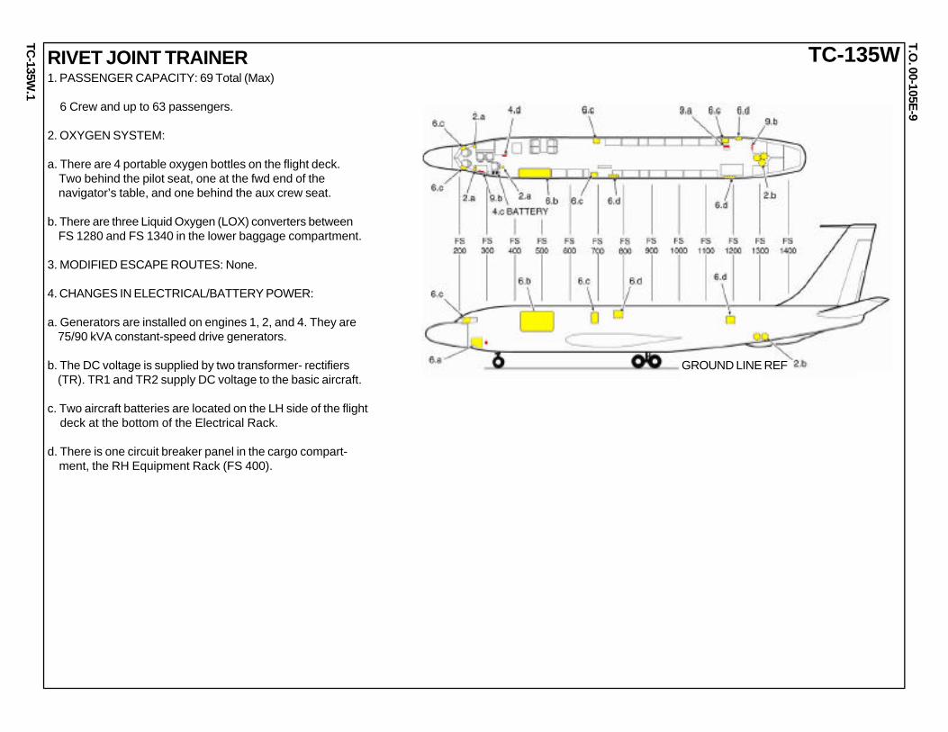
RIVET JOINT TRAINER1. PASSENGER CAPACITY: 69 Total (Max)
6 Crew and up to 63 passengers.
2. OXYGEN SYSTEM:
a. There are 4 portable oxygen bottles on the flight deck. Two behind the pilot seat, one at the fwd end of the navigator’s table, and one behind the aux crew seat.
b. There are three Liquid Oxygen (LOX) converters between FS 1280 and FS 1340 in the lower baggage compartment.
3. MODIFIED ESCAPE ROUTES: None.
4. CHANGES IN ELECTRICAL/BATTERY POWER:
a. Generators are installed on engines 1, 2, and 4. They are 75/90 kVA constant-speed drive generators.
b. The DC voltage is supplied by two transformer- rectifiers (TR). TR1 and TR2 supply DC voltage to the basic aircraft.
c. Two aircraft batteries are located on the LH side of the flight deck at the bottom of the Electrical Rack.
d. There is one circuit breaker panel in the cargo compart- ment, the RH Equipment Rack (FS 400).

TC-135W
.
TC-135WT.O
. 00-105E-9
5. HINDRANCES: None.
6. NORMAL/MANUAL/EMERGENCY ENTRY:
a. Normal Entry: Use crew entry door beneath the flight deck on the LH side of the aircraft. The outer door latch handle is located behind the access panel at the aft edge of the door. Pull handle firmly to release door.
CAUTION
Door opens down and forward.
b. The cargo door can only be opened from the inside. When aircraft power is available, the cargo door is operated by electrically controlled hydraulic pump. When no power is available, the pump must be manually operated.
c. Emergency Exits: There are five emergency exits: pilot’s sliding window, co-pilot’s sliding window, LH side and RH side over-wing hatches at FS 700, and the aft RH side hatch at FS 1160.
NOTE Escape ropes are installed above pilot and co-pilot sliding windows and the aft hatch.
d. Skin Penetration Points: There are skin penetration points on the LH side at approximately FS 780 and FS 1180 WL 230, and on the RH side at approximately FS 1200 WL 230.
2
FUEL TANKS AND CAPACITIES(IN US GALLONS)
RIVET JOINT TRAINER-Continued

TC-135W
.
TC-135WT.O
. 00-105E-9
3
7. ENGINE SHUTDOWN: The location and position of engine throttle levers, fuel selector switches/levers, master and battery switch, engine fire shutdown switches and T-handles are the same as the C-135.
8. AIRCREW EXTRACTION:a. Crew seat controls and adjustments: (1) Armrest adjustment is located below the front part of the armrest and controls the downward position of the armrest.
(2) Seat forward/backward movement is controlled by the front handle on either side of the pilot and copilot seats. The forward/backward movement of operator seats is con- trolled by lifting rod under the seat, then sliding seat in desired direction.
(3) The operator seats can be rotated 360 degrees using right front handle below the seat.
b. Pilot, copilot, and operator seat restraint belt release is lo- cated at the central harness connection point. To release the restraints, facing the crewmember, turn the center part of the connection counter-clockwise.
c. Troop, crew rest and observer seats have lap belts only.
9. SURVIVAL EQUIPMENT:a. A 4-man life raft is stowed above the aft RH exit. Additional 20-man life rafts can be stowed by securing to the floor when mission requirements dictate.
b. The aircraft has two emergency equipment panels: one above the crew entry chute, one at FS 1260 on the fwd wall of the galley. Emergency equipment panels may include a crash axe, first aid kit(s), fire fighters mask, and Halon fire extinguisher(s).
PILOT/COPILOT SEAT
OPERATOR SEAT
8b
8a(1)
8a(1) 8a(2)
8a(2)
8b
8a(3)
8a(1)
RIVET JOINT TRAINER-Continued
8a(1)

WC
-135C.
WC-135CT.O
. 00-105E-9
1
GROUND LINE REF
WEATHER1. PASSENGER CAPACITY: 10
2. OXYGEN SYSTEM:
a. There are 10 portable oxygen bottles. There are five on the flight deck; two behind the pilot’s seat, one behind the copilot’s seat, one at the aft end of the navigator’s table, and one beside the aux crew seat. On the RH side, there are two at FS 650. On the LH side, there is one on the operator console at FS870 and two at FS 1250.
b. There are two Liquid Oxygen (LOX) converters between FS 1280 and FS 1340 in the lower baggage compartment.
3. MODIFIED ESCAPE ROUTES: None.
4. CHANGES IN ELECTRICAL/BATTERY POWER:
a. Generators are installed on engines 1, 2, and 4. They are 75/90 kVA constant-speed drive generators.
b. The DC voltage is supplied by three transformer-rectifiers (TR). Two 100-amp TRs, TR1 and TR2, supply DC voltage to the basic aircraft. One 200-amp TR, TR3, supplies DC voltage to the special equipment in the cargo compartment.
c. The aircraft battery is located on the floor forward of the LH over wing hatch at FS 620.
d. There is one additional circuit breaker panel located at FS 960 which provides power to equipment in the cargo compartment. See Illustration.

WC
-135C.
WC-135CT.O
. 00-105E-9
5. HINDRANCES: Special and electronic equipment exists on the right side from FS 420 to FS 600 and from FS 900 to FS 1040. On the LH side equipment exists from FS 545 to FS 680; from FS 820 to FS 1020; from FS 1060 to FS 1160, and from FS 1280 to FS 1380.
6. NORMAL/MANUAL/EMERGENCY ENTRY:
a. Normal Entry: Use crew entry door beneath the flight deck on the LH side of the aircraft. The outer door latch handle is located behind the access panel at the aft edge of the door. Pull handle firmly to release door.
CAUTION
Crew entry door opens down and forward.
b. The cargo door can only be opened from the inside. When aircraft power is available, the cargo door is operated by electrically controlled hydraulic pump. When no power is available, the pump must be manually operated.
c. Emergency Exits: There are five emergency exits: pilot’s sliding window, co-pilot’s sliding window, LH side and RH side over-wing hatches at FS 700, and the aft RH side hatch at FS 1160.
NOTE Escape ropes are installed above pilot and co-pilot sliding windows, as well as above the aft hatch.
d. Skin Penetration Points: There is one skin penetration point on the RH side at approximately FS 900.
2
FUEL TANKS AND CAPACITIES(IN US GALLONS)
WEATHER-Continued
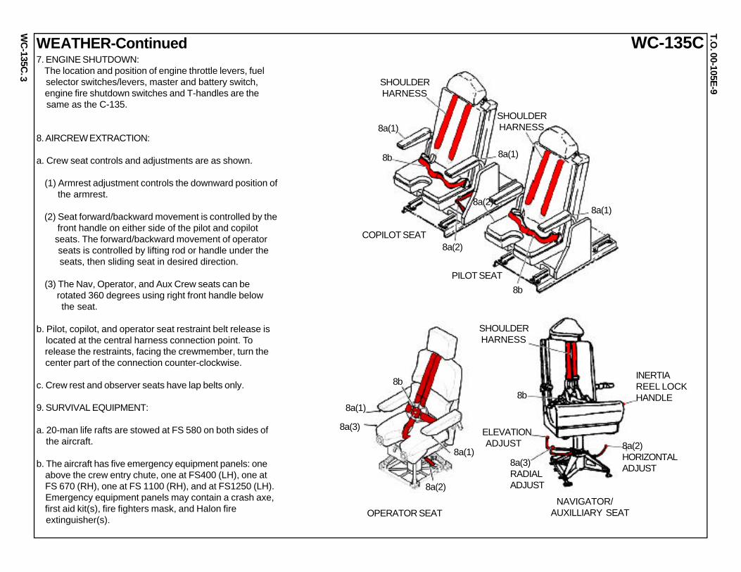
WC
-135C.
WC-135CT.O
. 00-105E-9
3
COPILOT SEAT
OPERATOR SEAT
8b
8a(1)
8a(1)
8a(2)
8b
8a(3)
8a(1)
WEATHER-Continued
8a(1)
NAVIGATOR/AUXILLIARY SEAT
8a(2)
SHOULDER HARNESS
INERTIAREEL LOCKHANDLE
8a(2)HORIZONTALADJUST8a(3)
RADIALADJUST
ELEVATION ADJUST
8b
7. ENGINE SHUTDOWN: The location and position of engine throttle levers, fuel selector switches/levers, master and battery switch, engine fire shutdown switches and T-handles are the same as the C-135.
8. AIRCREW EXTRACTION:
a. Crew seat controls and adjustments are as shown.
(1) Armrest adjustment controls the downward position of the armrest.
(2) Seat forward/backward movement is controlled by the front handle on either side of the pilot and copilot seats. The forward/backward movement of operator seats is controlled by lifting rod or handle under the seats, then sliding seat in desired direction.
(3) The Nav, Operator, and Aux Crew seats can be rotated 360 degrees using right front handle below the seat.
b. Pilot, copilot, and operator seat restraint belt release is located at the central harness connection point. To release the restraints, facing the crewmember, turn the center part of the connection counter-clockwise.
c. Crew rest and observer seats have lap belts only.
9. SURVIVAL EQUIPMENT:
a. 20-man life rafts are stowed at FS 580 on both sides of the aircraft.
b. The aircraft has five emergency equipment panels: one above the crew entry chute, one at FS400 (LH), one at FS 670 (RH), one at FS 1100 (RH), and at FS1250 (LH). Emergency equipment panels may contain a crash axe, first aid kit(s), fire fighters mask, and Halon fire extinguisher(s).
PILOT SEAT
8a(2)
SHOULDER HARNESS
SHOULDER HARNESS
8b
8a(1)

WC
-135W.
T.O. 00-105E
-9
WC-135W
1
WEATHER
GROUNDLINE REF
1. PASSENGER CAPACITY: 12
2. OXYGEN SYSTEM:
a. There are 16 portable oxygen bottles. There are five on the flight deck; two behind the pilot’s seat, one behind the copilot’s seat, one aft of the Nav station, and beside the aux crew seat. On the RH side, there are two at FS 1190 and three at FS 1240. On the LH side, there are two at FS 400, one at FS820, and three at FS 1240.
b. There are six Liquid Oxygen (LOX) converters between FS 1280 and FS 1340. There are two in the aft lower baggage compartment, two in the LH latrine area, and two in the RH latrine area.
3. MODIFIED ESCAPE ROUTES: None.
4. CHANGES IN ELECTRICAL/BATTERY POWER:
a. Generators are installed on engines 1, 2, and 4. They are 40 kVA constant-speed drive generators.
b. The DC voltage is supplied by four transformer- rectifiers (TR). TR1 and TR2 supply DC voltage to the basic aircraft. TR3 and TR4 supply DC voltage to the special equipment in the cargo compartment.
c. Two aircraft batteries are located on the flight deck at the bottom of the Electrical Rack (LH side).
d. There is one circuit breaker panel located in the cargo compartment (FS 790) to protect the special and electronic equipment. See illustration.
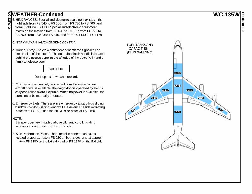
WC
-135W.
T.O. 00-105E
-9
WC-135W
2
WEATHER-Continued
FUEL TANKS AND CAPACITIES(IN US GALLONS)
5. HINDRANCES: Special and electronic equipment exists on the right side from FS 540 to FS 600; from FS 720 to FS 760; and from FS 980 to FS 1100. Special and electronic equipment exists on the left side from FS 545 to FS 600; from FS 720 to FS 760; from FS 810 to FS 840, and from FS 1140 to FS 1160.
6. NORMAL/MANUAL/EMERGENCY ENTRY:
a. Normal Entry: Use crew entry door beneath the flight deck on the LH side of the aircraft. The outer door latch handle is located behind the access panel at the aft edge of the door. Pull handle firmly to release door.
CAUTION
Door opens down and forward.
b. The cargo door can only be opened from the inside. When aircraft power is available, the cargo door is operated by electri- cally controlled hydraulic pump. When no power is available, the pump must be manually operated.
c. Emergency Exits: There are five emergency exits: pilot’s sliding window, co-pilot’s sliding window, LH side and RH side over-wing hatches at FS 700, and the aft RH side hatch at FS 1160.
NOTE: Escape ropes are installed above pilot and co-pilot sliding windows, as well as above the aft hatch.
d. Skin Penetration Points: There are skin penetration points located at approximately FS 920 on both sides, and at approxi- mately FS 1180 on the LH side and at FS 1190 on the RH side.

WC
-135W.
T.O. 00-105E
-9
WC-135WWEATHER-Continued
3
PILOT/COPILOT SEAT
OPERATOR SEAT
8b
8a(1)
8a(2)
8b
8a(3)
8a(1)
8a(1)
8a(2)
SHOULDER HARNESS
INERTIAREEL LOCKHANDLE
8a(2)HORIZONTALADJUST
8a(3)RADIALADJUST
ELEVATION ADJUST
8b
8a(1)
NAVIGATOR/AUXILLIARY SEAT
7. ENGINE SHUTDOWN:
The location and position of engine throttle levers, fuel selector switches/levers, master and battery switch, engine fire shutdown switches and T-handles are the same as the C-135.
8. AIRCREW EXTRACTION:
a. Crew seat controls and adjustments:
(1) Armrest adjustment is located below the front part of the armrest and controls the downward position of the armrest.
(2) Seat forward/backward movement is controlled by the front handle on either side of the pilot and copilot seats. The forward/backward movement of operator seats is controlled by lifting rod under the seat, then sliding seat in desired direction.
(3) The operator seats can be rotated 360 degrees using right f front handle below the seat.
b. Pilot, copilot, and operator seat restraint belt release is located at the central harness connection point. To release the restraints, facing the crewmember, turn the center part of the connection counter-clockwise.
c. Crew rest and observer seats have lap belts only.
9. SURVIVAL EQUIPMENT:
a. 20-man life rafts are secured to the floor at FS 760.
b. The aircraft has two emergency equipment panels: one above the crew entry chute and one at FS 1260 on the forward wall of the galley. Equipment panels may include a crash axe, first aid kit(s), fire fighters mask, and Halon fire extinguisher(s).