Embed Size (px)
Citation preview

TO GO DIRECTLY TO THE TECHNICAL ORDER, CLICK ON THE CONTINUE BUTTON.
WELCOME TO TECHNICAL ORDER 00-105E-9, 1 FEBRUARY 2006, REVISION 11.
TO SEE THE SEGMENT INFORMATION CHANGE NOTICE, CLICK ON THE NOTICE BUTTON.
TO CONTACT THE TECHNICAL CONTENT MANAGER , CLICK ON THE CONTACT BUTTON.
CONTINUE
NOTICE
CONTACT
TO NAVIGATE
CLICK ON THEBOOKMARKS ANDCLICK ON THE (+)SYMBOLS, THEN
CLICK ON SUBJECTLINKS TO GO TOSPECIFIC VIEWS
IN THIS SEGMENT.
THIS IS SEGMENT 22 COVERING CHAPTER 19 FROM THE USCG TO NOAA.

TECHNICAL ORDER 00-105E-9 TECHNICAL CONTENT MANAGER
WRITTEN CORRESPONDENCE:
HQ AFCESA/CEXFATTN: Fire and Emergency Services Egress Manager139 Barnes Drive Suite 1Tyndall AFB, Florida 32403-5319
E-MAIL: [email protected]
INTERNET: HQ AFCESA Fire and Emergency Services PUBLIC WEB PAGE: http://www.afcesa.af.mil/CEX/cexf/index.asp Safety Supplements: http://www.afcesa.af.mil/CEX/cexf/_firemgt.asp
PHONE: (850) 283-6150DSN 523-6150
FAX: (850) 283-6383DSN 523-6383
For technical order improvements, correcting procedures, and other inquiries,please use the above media most convenient.

This page is provided to notifiy the user of any informational changes made to Technical Order 00-105E-9 in this Segment and the currentRevision. Informational changes will be referenced in the Adobe Reader’s Bookmark tool as a designator symbol illustrated as a <[C]> forquick reference to the right of the affected aircraft. The user shall insure the most current information contained in this TO is used for hisoperation. Retaining out of date rescue information can negatively affect the user’s operability and outcome of emergencies. If the user printsout pages his unit requires, the user shall print the affected page(s), remove and destroy the existing page(s), and insert the newly printedpage(s) in the binder provided for that purpose. A Master of this TO shall be retained in the unit’s library for reference, future printingrequirements and inspections.
CHAPTER AIRCRAFT PAGE EXPLANATION OF CHANGE
SEGMENT 22 INFORMATION CHANGE NOTICE
None.

TO 00-105E-9
Chapter 19 Cover
NOTE
Chapter 19 contains emergency rescue andmishap response information for the following aircraft:
USCG HC-130**USCG HH-60J**USCG HU-25NOAA 212**NOAA CITATION IINOAA WP-3D**NOAA AC-690NOAA LA-27NOAA G-IV**NOAA AC-500SNOAA DH-6NOAA MD-500DUSFS Aero Commander**USFS Air Tractor AT-802USFS Beechcraft 58P BaronUSFS Boeing 727**USFS Boeing 737**USFS Boeing KC-97USFS C-130 Hercules**USFS CASA C-212 Aviocar**USFS Cessna 337/ Skymaster O-2**USFS CH-46 Sea Knight/Vertol 107**USFS CH-47 Chinook**USFS CL-415 Super ScooperUSFS Convair 580USFS DC-3 Douglas TurbineUSFS DC-4 AirlinerUSFS DC-6 Airliner**USFS DC-7 Airliner**USFS DCH-2 Beaver**USFS DCH-6 Twin Otter**USFS Fokker F-27**USFS Grumman S-2F Tracker**USFS H-43 HuskieUSFS Lookheed P2V Neptune**USFS Lookheed SP2H**USFS Model 90 King Air**USFS P-3 Orion**USFS PB4Y-2 PrivateerUSFS Rockwell OV-10USFS S-64 Skycrane**USFS S-70/UH-60**USFS SH-3 Sea King**USFS Shorts SD 330/C-23**
* Aircraft information pending** See like aircraft in manual

TO 00-105E-9
Chapter 19 Cover
NOTE
Chapter 19 contains emergency rescue andmishap response information for the following aircraft:
USFS Aerospatiale AS 350USFS Bell 204B/UH-1A,B,C**USFS Bell 204/UH-1D,H**USFS Bell 206B/OH-58**USFS Bell 206L-3/OH-58**USFS Bell 212/412**USFS Bell 214USFS Bell 222USFS Boeing/Vertol 234USFS Eurocopter BK-117USFS Eurocopter BO-105**USFS Fairchild Hiller FH-1100USFS McDonnell Douglas 500-C,DUSFS Sikorsky S-58T
* Aircraft information pending** See like aircraft in manual

T.O. 00-105E-9
19-1. INTRODUCTION AND USE.
19-2. This section contains emergency rescue andmishap response information illustrations in alpha-numerical order relative to type and model of aircraft.This arrangement of illustrations is maintained fromChapter 4 throughout the remainder of the publica-tion.
19-3. GENERAL ARRANGEMENT.
19-4. Aircraft type designation has been positionedin the upper right corner of the horizontal illustrationfor rapid identification. Additional aids to rapid orien-tation are:
a. Recent technological advances in avia-tion have caused concern for the modern firefighter.Aircraft hazards, cabin configurations, airframe ma-terials, and any other information that would be help-ful in fighting fires, the locating and rescue of per-sonnel will be added as the information becomes avail-able.
b. Suggested special tools/equipment arelisted in the upper left corner, on the Aircraft/Entrypage of each listed aircraft.
c. Procedural steps covering emergency/normal entrances, cut-ins, engine/APU shutdown,safetying ejection/escape systems, and aircrew ex-traction are outlined on the left side of each page withcoordinated illustrations on the right.
d. Illustrations located on right side of pagesare coordinated with text by numerals and small let-ters depicting both paragraph and subparagraph onthe page.
e. Each illustration is consistently coloredand/or pattern keyed to highlight essential emergencyrescue information.
f. Details are pulled directly from the illustra-tion to highlight an area, thus eliminating unneces-sary searching for desired information.
CHAPTER 19
U.S. GOVERNMENT
VARIOUS AGENCIES
AEROSPACE EMERGENCY RESCUEAND MISHAP RESPONSE INFORMATION
17-5. AGENCY PLATFORMS.
17-6. Most aircraft in these active inventories are in-cluded in this manual. Those aircraft not yet includedwill be added in the near future.
a. FAA Platforms are: Boeing 727-25C,Convair CV-580, Beech King Air BE-200, Aero Com-mander AC-680E, and Sikorsky S-76A.
b. Dept of Energy Platforms are intensivelymodified to perform their specialized missions andmany are inherently unavailable for other applications.DOE uses a Gulfstream 159 for airborne atmosphericresearch and, for climate research, a Cessna-172Nand various Unmanned Aerospace Vehicles(UAVs) and a DeHavilland DCH-6 Twin Otter chaseplane in support of DOE’s Atmospheric RadiationMeasurements program.
c. Federal Research aircraft available foroceanographic research, helps to promote interagencycooperation, coordination, and scheduling of assets.The National Oceanographic Partnership Program(NOPP) is a collaboration of fifteen Federal agenciesto provide leadership and coordination of nationaloceanographic research and education programs.
NOPP Agencies with Participating AircraftDOE, National Science Foundation, FAA*, Office ofNaval Research, NASA, U.S.C.G. and NOAA.
*Not a member of NOPP
Other NOPP AgenciesArmy Corps of Engineers Minerals Management Ser-vice, Defense Advanced Research Projects, Office ofManagement and Budget, Department of HomelandSecurity, Office of Science and Technology PolicyDepartment of State U.S. Geological Survey, EPA andNaval Research Laboratory.
d. The U.S. Immigrations and Customs En-forcement (ICE) aircraft are PC-12, UH-60A,Eurocopter AS-350 and Cessna Citation II.

HC
-130.
HC-130T.O
. 00-105E-9
1
The aircraft information is located in Chapter 6 containing USAF aircraft.

HH
-60J.
HH-60JT.O
. 00-105E-9
The aircraft information is located in Chapter 13 containing USAF aircraft.
1

HH
-65A.
HH-65AT.O
. 00-105E-9
AIRCRAFT PAINT SCHEMES
1
HH
-65A.
HH-65AT.O
. 00-105E-9
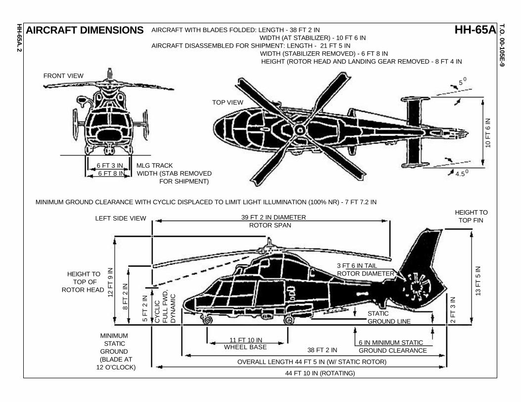
AIRCRAFT DIMENSIONS
2
6 FT 3 IN MLG TRACK6 FT 8 IN WIDTH (STAB REMOVED FOR SHIPMENT)
5
4.5
0
0
10 F
T 6
IN
13 F
T 5
IN
2 FT
3 IN
12 F
T 9
IN
8 FT
2 IN
5 FT
2 IN
CY
CLI
CFU
LL F
WD
,D
YN
AM
IC
39 FT 2 IN DIAMETER ROTOR SPAN
3 FT 6 IN TAILROTOR DIAMETER
11 FT 10 IN
38 FT 2 IN
OVERALL LENGTH 44 FT 5 IN (W/ STATIC ROTOR)
44 FT 10 IN (ROTATING)
STATICGROUND LINE
6 IN MINIMUM STATICGROUND CLEARANCE
HEIGHT TO TOP FIN
WHEEL BASE
TOP VIEW
FRONT VIEW
LEFT SIDE VIEW
HEIGHT TO TOP OFROTOR HEAD
MINIMUM STATIC GROUND (BLADE AT12 O’CLOCK)
AIRCRAFT WITH BLADES FOLDED: LENGTH - 38 FT 2 IN WIDTH (AT STABILIZER) - 10 FT 6 INAIRCRAFT DISASSEMBLED FOR SHIPMENT: LENGTH - 21 FT 5 IN WIDTH (STABILIZER REMOVED) - 6 FT 8 IN HEIGHT (ROTOR HEAD AND LANDING GEAR REMOVED - 8 FT 4 IN
MINIMUM GROUND CLEARANCE WITH CYCLIC DISPLACED TO LIMIT LIGHT ILLUMINATION (100% NR) - 7 FT 7.2 IN

HH
-65A.
HH-65AT.O
. 00-105E-9
3
AIRCRAFT GENERAL INFORMATION
1 RADOME 2 INSTRUMENT PANEL 3 CYCLIC (2) 4 FREE AIR TEMPERATURE PROBE 5 VHF/FM RADIO ANTENNA 6 RESCUE HOIST 7 ALTERNATOR (2) 8 ROTOR HEAD 9 OMNIDIRECTIONAL AIR DATA PROBE10 ROTATING SMASHPLATE11 MAIN GEARBOX12 GSP ANTENNA13 DRIVE COUPLING SHAFT14 STARTER/GENERATOR (2)15 ENGINE (2)16 ROTOR BLADE17 AIRCONDITIONER HEAT EXCHANGER18 ECS AIR INTAKE19 ECS AIR EXHAUST20 HF RADIO ANTENNA21 TAIL ROTOR22 VERTICAL STABILIZER23 UHF/VHF COMM 1 & TCAS ANTENNA24 ANTICOLLISION LIGHT25 POSITION LIGHT
1
23
4 56
78
9
10 1112
1314 1517
16
18 19
21
22
2324
25
2620
25
2728
29303132
3433
353637383940
4142
26 TAIL SKID27 UHF/VHF COMM 2 RADIO ANTENNA28 VOR/ILS ANTENNA29 RADAR ALTIMETER ANTENNAS30 UHF/DF ANTENNA31 FLOTATION EQUIPMENT BAY (2 SHOWN)32 FUEL DUMP FAIRING (OUT OF VIEW)33 GRAVITY REFUELING RECEPTACLES (2)34 EXTERNAL AIR CONDITIONING RECEPTACLES35 MAIN LANDING GEAR36 AVIONICS EQUIPMENT RACK (SEE RT VIEW)37 SEARCH LIGHT38 CARGO HOOK39 MARKER BEACON ANTENNA40 TACAN ANTENNA41 LOUD HAILER (NOT PERMANENTLY INSTALLED)42 CREW SEATS (3)43 ADF LOOP ANTENNA (LT) TCAS ANTENNA (RT)44 COLLECTIVE (2)45 HOVER LIGHT (LT) LANDING LIGHT (RT)46 NOSE LANDING GEAR47 BATTERY48 SEARCH/WEATHER RADAR49 PILOT PROBES (2)50 DIRECTIONAL CONTROL PANELS
4344453146474849
50
2324
2526271
23 4 5 6 7 8 9 10 11
1213141516
17
18192021
22
DETAILED VIEW OF AVIONICS RACK LOOKING OUTBOARD
1 AVIONICS RACK FAN 2 AUXILLARY AUDIO CONTROL PANEL 3 ALTITUDE CONTROLLER 4 LOUDHAILER AMPLIFIER 5 NO.1 SYSTEM COUPLER COMPUTER (SCC) 6 COMM 1 UHF/VHF 7 TACAN 8 OMNIDIRECTIONAL AIR DATA SYSTEM (OADS) 9 AUDIO MIXER10 NO.2 SYSTEM COUPLER COMPUTER (SCC)11 IFF12 VOICE FLIGHT DATA RECORDER (VFDR)13 IFF KIT 1C (PROVISIONAL) OR TCAS TRC7914 VHF/FM15 AVIONICS RACK CIRCUIT BREAKER PANEL16 GPS RECEIVER17 SIGNAL INTERFACE UNIT (SIU)18 MISSION COMPUTER UNIT (MCU)19 COPILOT’S DISPLAY DRIVER UNIT (DDU)20 RATE GYROS AND ACCELEROMETERS21 FLIGHT DIRECTOR COMPUTER (FDC)22 COMM 2 VHF/UHF23 PILOT’S DISPLAY DRIVER UNIT (DDU)24 AFCS COMPUTER25 ADF26 AIRSPEED SENOR27 NO 1 VOR/ILS NAV RECEIVER

HH
-65A.
HH-65AT.O
. 00-105E-9
4
COCKPIT CABIN BAGGAGE COMPARTMENT
9 FRAME MK-25 FLARES
AVIONICS RACK
0
SAR BOARD
1. AIRFRAME MATERIALS
The cockpit, cabin and baggage compartment is constructed primarily of longitudinal, alluminum alloy beams and non-metallic honeycomb laminated with fiberglass with a metal covering that supports the vertical fin and a fixed horizontal stabilizer. Graphic illustrates the 9 Frame and basic interior of the HH-65A.0
AIRFRAME MATERIALS

HH
-65A.
HH-65AT.O
. 00-105E-9
5
AIRCRAFT FUEL SYSTEM AND CAPACITIES
#1 FUEL SYSTEM
#2 FUEL SYSTEM
1. AIRCRAFT FUEL SYSTEM
a. The fuel system has 5 cells, located beneath the floor panel in seal compartments. The 5 cells are divided into 2 systems. The #1 system has 3 cells and #2 has 2 cells. This arrangement minimizes lateral and longitudinal center of gravity changes as fuel is consumed. Each system has a feeder tank located in its center tank for it’s respective engine. Each system is vented to an expansion tank mounted in the baggage compartment.
2. FUEL CAPACITY CHART
RIGHTCENTER
RIGHTFORWARD
AFTLEFTCENTERLEFT
FORWARD
FUEL CAPACITY LEFT SYSTEM (#1) RIGHT SYSTEM (#2)
TANKS PRESSURE FUELING GRAVITY FUELING PRESSURE FUELING GRAVITY FUELING GALS POUNDS GALS POUNDS GALS POUNDS GALS POUNDS
JP-4 JP-5 JP-8 JP-4 JP-5 JP-8 JP-4 JP-5 JP-8 JP-4 JP-5 JP-8RIGHT FWD 39.6 257 269 265 43.8 285 298 293LEFT FWD 37.0 241 252 248 42.5 276 289 285LEFT CTR 59.6 387 405 399 55.4 360 377 371RIGHT CTR 71.6 463 487 480 59.1 384 402 396AFT 74.3 486 509 501 82.7 577 603 594
TOTAL 136.2 885 926 912 141.7 921 964 949 146.4 952 996 981 147.8 961 1005 990

HH
-65A.
HH-65AT.O
. 00-105E-9
6
FUEL AND STATIC SYSTEMS
PITOT STATICSYSTEMDRAINING(PITOT HEAD)
PITOT STATICSYSTEM DRAINING(STATIC SYSTEM)
FUEL SUMP DRAIN VALVES
1. DRAINING/BLEEDING POINTS
NOTE: Servicing also includes the use of aircraft draining and bleeding points. These are provided for the pitot-static system and fuel sump draining as well as the hydraulic system. The points may be a source of flammable hazards.
2. GRAVITY REFUELING PANEL
NOTE: The gravity refueling panel is located above the left main landing gear. The location of the panel and components are illustrated to the right.
3. SINGLE POINT REFUELING (SPR) PANEL
NOTE: The pressure refueling receptacle is on a panel located above the right main landing gear.
PRESSURE RELIEF VALVE
LOCKING LEVERS
RIGHT FUEL SYSTEMFILLER NECK CAP
LEFT FUEL SYSTEMFILLER NECK CAP
“D” RING
GRAVITY REFUELING PANEL
THREE WAYCONTROL VALVE
PRESSURE SHUTOFF VALVECONTROL (NORMAL POSITION)
PRESSURE SHUTOFFVALVE CONTROL(SHUTOFF POSITION)
FUEL CAP
SPR PANEL

HH
-65A.
HH-65AT.O
. 00-105E-9
7
PILOT DOOR
CO-PILOT DOOR
CABIN SLIDING DOOR CABIN WINDOW
CABIN HINGEDDOOR
EMERGENCY EXITS AND LOCATIONS1. EMERGENCY EXITS AND LOCATIONS
NOTE: An important item concerning helicopter ditching over water is the aircraft, almost always, turns upside down. This will complicate egress by the crew and passengers from the helicopter as well as rescue crews attempting to enter and extract personnel. Knowing where and how to operate these emergency exits become a matter of life and death.
2. PORTABLE FIRE EXTINGUISHER
a. A portable fire extinguisher is located between the pilot and co-pilot seats in the cockpit.
PORTABLE FIRE EXTINGUISHER
HH
-65A.
HH-65AT.O
. 00-105E-9
8
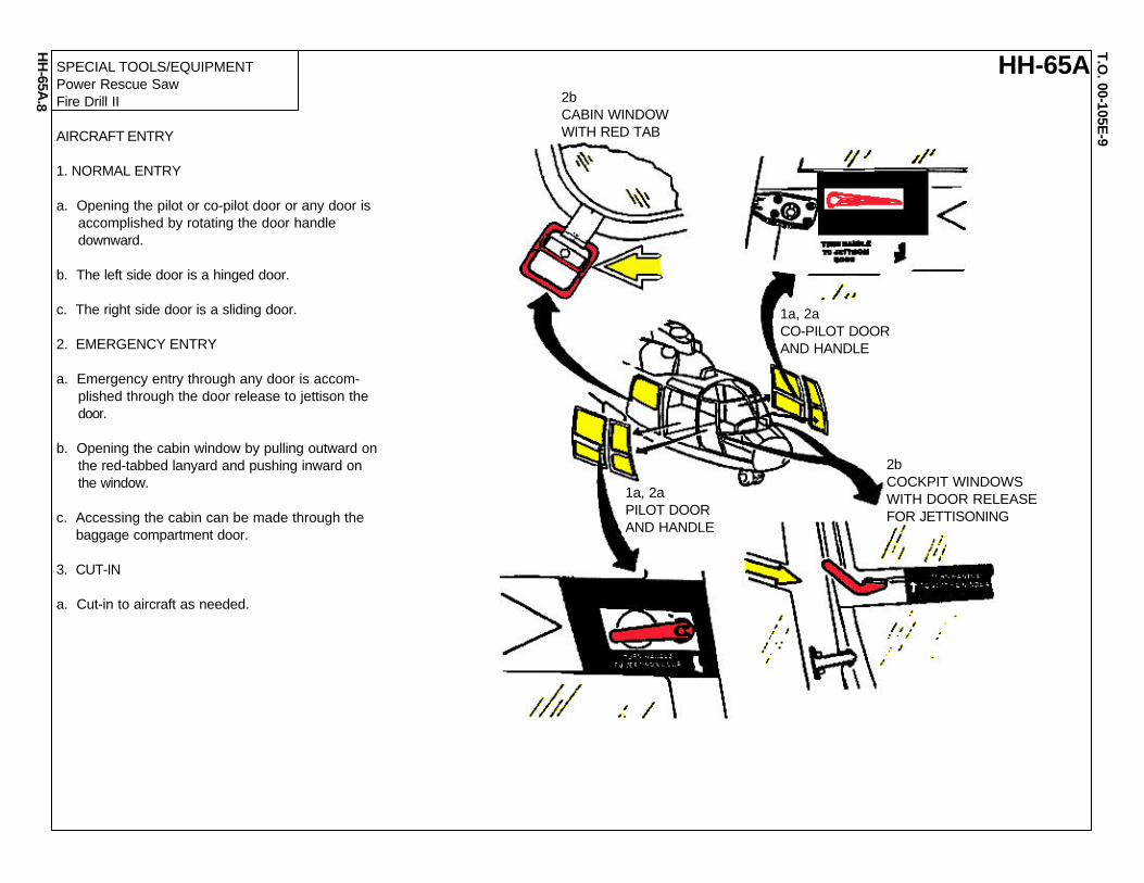
SPECIAL TOOLS/EQUIPMENTPower Rescue SawFire Drill II
AIRCRAFT ENTRY
1. NORMAL ENTRY
a. Opening the pilot or co-pilot door or any door is accomplished by rotating the door handle downward.
b. The left side door is a hinged door.
c. The right side door is a sliding door.
2. EMERGENCY ENTRY
a. Emergency entry through any door is accom- plished through the door release to jettison the door.
b. Opening the cabin window by pulling outward on the red-tabbed lanyard and pushing inward on the window.
c. Accessing the cabin can be made through the baggage compartment door.
3. CUT-IN
a. Cut-in to aircraft as needed.
1a, 2aPILOT DOORAND HANDLE
1a, 2aCO-PILOT DOORAND HANDLE
2bCABIN WINDOWWITH RED TAB
2bCOCKPIT WINDOWSWITH DOOR RELEASEFOR JETTISONING

HH
-65A.
HH-65AT.O
. 00-105E-9
9
ENGINE SHUTDOWN AND FIRE WARNING OVERHEAD CONTROL QUADRANT
1aFLOW FUELCONTROLLEVERS
ROTOR BRAKECONTROL LEVER
2aEMERGENCY FUELSHUTOFF CONTROL LEVERS
1. ENGINE SHUTDOWN
NOTE: There are two Fuel Flow Control Levers, one for each engine, are located on the overhead control quadrant. There are three detent positions on the 100 degree range: SHUTOFF, IDLE AND FLIGHT. The detents can be passed by pulling the lever to the right and moving it beyond the detent. A mechanical interlock prevents the levers from being moved forward of the IDLE position when the rotor brake is applied.
a. Pull the Fuel Flow Control Levers to the SHUTOFF position.
2. EMERGENCY SHUTDOWN
NOTE: There are two emergency Fuel Shutoff Control Levers, one for each engine, are located on the overhead control quadrant. Each lever is used for emergency shutdown of the respective engine in the event of a fire within the engine compartment or in case of malfunction in the engine gas genera- tor speed control system. The levers are breakaway wired in the OPEN (forward) position.
a. Pull the Fuel Shutoff Control Levers to the AFT position to shut off all fuel flow.
3. ENGINE FIRE WARNING CONTROL PANEL
NOTE: The Engine Fire Warning Control Panel is located at the center of the instrument panel.
a. In case of fire, the Fire/Fail Lights will illuminate.
b.. Push the appropriate Fire Extinguisher push button, located just above the Fire/Fail lights.
3bFIRE EXTINGUISHERPUSH-BUTTONS
3aFIRE/FAIL LIGHTS
FIRE TEST/FAIL TEST SWITCHES
ENGINE FIRE WARNING CONTROL PANEL

HH
-65A.
HH-65AT.O
. 00-105E-9
10
ENGINE FIRE EXTINGUISHER BOTTLES
2bPRESSURE GAGE
2bDISCHARGE HEADS
2bENGINE FIREEXTINGUISHERBOTTLES
1. ENGINE FIRE EXTINGUISHER BOTTLES
a. The engine fire extinguisher system is designed to extinguish fires in the engine compartment and is comprised of :
- Two spherical bottles- Distribution system- Engine fire warning/control panel- Low pressure warning system
b. The characteristics of the fire extinguisher bottles are:- Each bottle is mounted aft of it’s respective engine bay in a fire protected area- Equipped with dual discharge heads- Extinguishing agent is released by explosive squibs- Contains the agent Bromotriflouromethane- Pressurized to 600 - 626 PSI at 21.1 Celsius.- Each equipped with a pressure gage
c. The engine fire extinguisher distribution system mainly consists of distribution lines connected to the explosive squibs that route the extinguishing agent to the selected engine.
2cDISTRIBUTION LINES
0
HH
-65A.
HH-65AT.O
. 00-105E-9
11
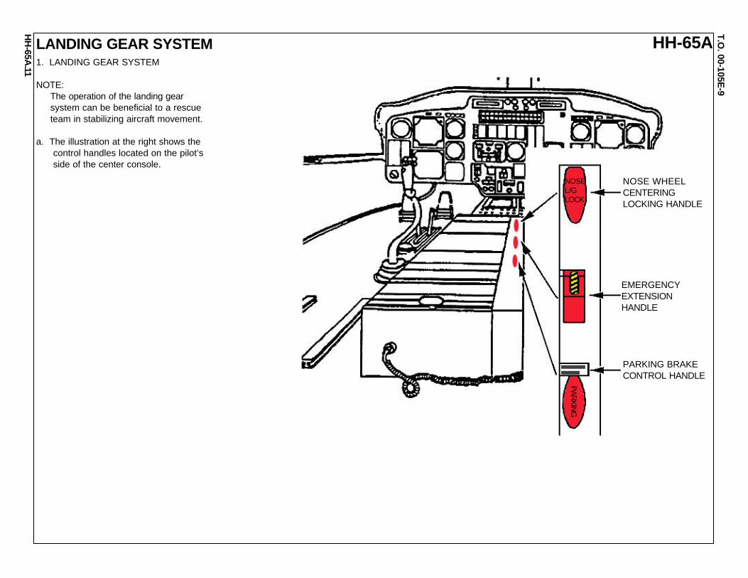
LANDING GEAR SYSTEM
NOSEL/GLOCK
PARKIN
G
PARKING BRAKECONTROL HANDLE
EMERGENCYEXTENSIONHANDLE
NOSE WHEELCENTERINGLOCKING HANDLE
1. LANDING GEAR SYSTEM
NOTE: The operation of the landing gear system can be beneficial to a rescue team in stabilizing aircraft movement.
a. The illustration at the right shows the control handles located on the pilot’s side of the center console.

HH
-65A.
HH-65AT.O
. 00-105E-9
12
MAIN LANDING GEAR WHEEL BRAKE SYSTEM1. MAIN LANDING GEAR WHEEL BRAKE SYSTEM
NOTE: The brake can be useful during rescue operations to prevent the aircraft from movement.
a. The illustration to the right shows the location and operation of the parking brake handle and brake control cable to the brake control valve of the secondary hydraulic system.
PARKING BRAKE HANDLE(IN THE LOCKED, PULLED POSITION)
1aPARKINGBRAKEHANDLE
1aBRAKECONTROLCABLE
HYDRAULIC SYSTEMPRESSURE FROM THE PEDAL CYLINDERS
1aBRAKECONTROLVALVE
1aSECONDARY HYDRAULIC SYSTEM
RETURNPRESSURE

HH
-65A.
HH-65AT.O
. 00-105E-9
13
TOWING PROCEDURES1. TOWING PROCEDURES
a. Connect tow bar to the ends of the nose landing gear tow bar adapter.
NOTE: While connecting the tow bar, ensure that the nose landing gear centering lock is in the unlocked position.
b. Connect tow bar to tow tractor.
c. Station required towing team members.
d. Release parking brake and remove main landing gear chocks.
CAUTION
Avoid sudden accelleration or deceleration. Do not turn nose landing gear before rolling to prevent tire distortion and slipping on rims.
e. Tow the aircraft.
NOTE: Turn radius: Limited to a 90 degree turn of the nose landing gear. Allow 23 feet minimum turning radius for clearance of the tailboom.
1aNOSE LANDINGGEAR TOW BAR
NOSE LANDING GEARCONNECT POINTS
23 FT
23 FT90
90180
0
00
UNLOCKED LOCKED
UNLOCKEDPOSITION
LOCKEDPOSITION
WARNING FLAG

T.O. 00-105E
-9
NO
AA
.
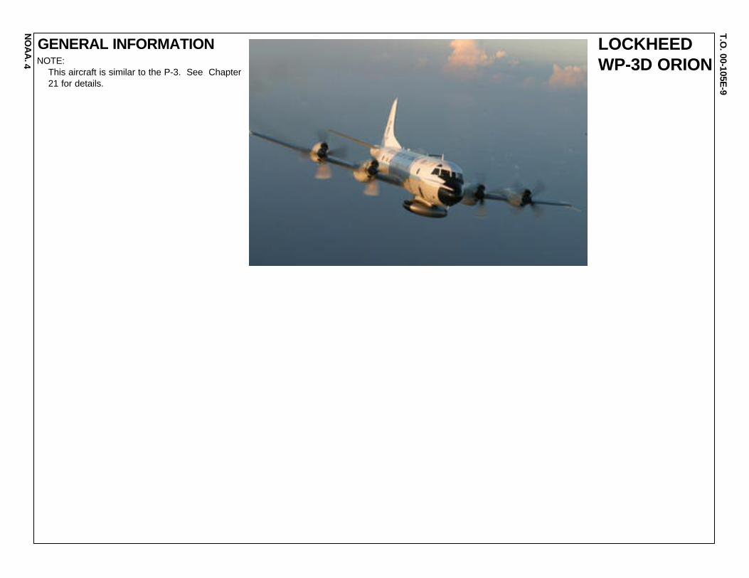
GENERAL INFORMATION
1 NATIONAL OCEANIC AND ATMOSPHERE ADMINISTRATION(NOAA) ACTIVE AIRCRAFT INVENTORY
NOTE: These aircraft will be cross referenced with other similar aircraft where appropriate.
GULFSTREAM IV (SP) G-IV
BELL 212
CESSNA CITATION II CE-550
GULFSTREAM TURBO COMMANDER AC-690
LAKE SEAWOLF LA-27
LOCKHEED WP-3D ORION MD 500D
DeHAVILLAND TWIN OTTER DH-6
ROCKWELL AERO COMMANDER AC-500S

T.O. 00-105E
-9
NO
AA
.
GENERAL INFORMATION BELL 212
2 NOTE: This aircraft is similar to the UH-1N “Twin Huey” See Chapter 9 for details.

T.O. 00-105E
-9
NO
AA
.
GENERAL INFORMATION CESSNACITATION II3 NOTE:
This aircraft is a business jet and does not have a similar military designation. Emergency rescue information pending.
The is Cessna Citation (CE-550) a versatile twin-engine jet aircraft modified for acquiring coastalremote sensing imagery. The aircraft can supporta wide variety of remote sensing configurations,including largeformat aerial photography as well asdata collection for digital cameras, hyperspectral,multispectral, and LIDAR systems. CessnaCitation (CE-550)
STANDARD AIRCRAFT SPECIFICATIONSType: Cessna Citation II/ Model 550Crew: 2 Pilots and 2-4 ScientistsCeiling: 43,000 feet (without supplemental cabin oxygenRate of Climb: 2500 ft/min at sea level (20 minutes toclimb to 30,000 ft)Cruise Airspeed: 350 knots (true)Scientific Power: 8 amps @ 115 volts (5 standard outlets) 50 amps @ 28 volts DCMax. Gross Weight: 14,600 lbsEmpty Weight: 7,800 lbsUseful Load: 6,800 lbs (fuel, personnel, cargo)Fuel Load: 5,008 lbsStandard Fuel Burn: Normal Cruise (98%): Range-1325 nm Duration-4 hrs15 min, Max. Cruise (104%): Range-1200 nm Duration-3 hrs 40min, Max. Endurance: Range-1610 nm Duration-5 hrsDimensions: Wing Span: 51 ft 8.4 in, Total Length: 47 ft 3 in, Fuselage Height: 4.8 ft, Tail Height:14 ft 9.6 inCabin Doors: 39 in x 21.25 inBaggage Doors (rear): 22 in x 27 inCabin Length: 20.9 ftCabin Width: 4.9 ftUseable Volume: 491 cu ftNose Baggage: 28 cu ftCabin Baggage: 947 cu ftCockpit: Color weather radar, radar altimeter, integrated flight director system, HF radio, GPS flight management systemCabin: Dual cameras: Wild RC-30 on the right side/Wild RC- 10 on the left side. Applanix POS/AV IMU system and laptop computer Cabin
T.O. 00-105E
-9
NO
AA
.
GENERAL INFORMATION
4
LOCKHEEDWP-3D ORIONNOTE:
This aircraft is similar to the P-3. See Chapter 21 for details.

T.O. 00-105E
-9
NO
AA
.
GENERAL INFORMATION
5
GULFSTREAMTURBOCOMMANDERAC-690
NOTE: This aircraft does not have a similar military designation. Emergency rescue information pending.
The Gulfstream Turbo Commander (AC-690) is astable high-winged twin, pressurized turbopropaircraft that is suitable for a variety of missions. Thestandard configuration allows for mission equip-ment, two pilots, and one photographer. However,with all seats installed, five scientists/techniciansmay be accommodated in the cabin. NOAA’s AC-690 Turbo Commander is utilized by the NGSRemote Sensing Division and the NOHRSC (Na-tional Operational Hydrologic Remote SensingCenter).
STANDARD AIRCRAFT SPECIFICATIONSType: Rockwell AC690A TurboCommanderEngines: Garrett TPE 331-5-251KCrew: 2 Pilots + 5 Scientists
Ceiling: 31,000 feetRate of Climb: 3000 feet/minuteOperational Airspeeds: 120 - 250 ktsElectrical: Two 28 VDC generators, 110 VACScientific Power: 28 VDC, 110 VAC
Max. Gross Weight: 10,250 lbs.Empty Weight: 6830 lbs.Useful Load: 3,420 lbs.Fuel Load: 384 US gallonsFuel Type: Jet A,B JP4,5,8
Standard Fuel Burn: Normal Cruise Speed - 60 to 90 gallons per hour, depending on altitude and missionDimensions (external): Wing Span: 46 ft. 7 in., Total Length, Length: 44 ft. 5 in., Tail Height: 14 ft. 12 in.Dimensions (internal): Cabin Door: 47 in. X 26.5 in. Baggage Door: 31.25 in. X 19.75 in. Baggage volume: 45 cubic ft.

T.O. 00-105E
-9
NO
AA
.
GENERAL INFORMATION
6
LAKESEAWOLFLA-27
NOTE: This aircraft does not have a similar military designation. Emergency rescue informa- tion pending.
The Lake Renegade Seawolf (LA-27) ia arugged, adaptable, single engine amphibiousaircraft designed for nearshore low-levelsurveys. The aircraft is equipped with externalfuel tanks, bubble windows, and NATOhardpoints. NOAA operates two of thesesingle turbo-charged piston engine amphibi-ous aircraft. A standard crew consists of onepilot and up to three scientists. The Lakeaircraft have been used for biological surveysincluding red drum, sea turtle and marinemammal surveys, as well as on site terrainobservations.STANDARD AIRCRAFT SPECIFICATIONSType Engines: AVCO Lycoming TI0540-AA1AD
Crew: 1 Pilot + 3 ScientistsCeiling: 12,500 feet (without supplemental cabin oxygen), 20,000 feet (with supplemental cabin oxygen)Rate of Climb: 800 feet/minuteOperational Airspeeds: 120 knotsElectrical: Two 70 ampere alternators
Max. Gross Weight: 3700 lbs. (weight above 3450 lbs should consist of under wing fuel/ stores)Empty Weight: 2450 lbsUseful Load: 1000 lbs (fuel, personnel, cargo)Fuel Load: 40 U.S. Gals main, 14 U.S. Gals, Auxilary tanks (7 Gals ea, usable), 34 U.S. Gals wing tanks (17 Gals ea), 34 U.S. Gals ea drop tankType Fuel: Aviation Gasoline 100 or 100LL
Maximum Range/Duration: 12 hours/ 1500 NMDimensions (external): Length 28’9”, Wing Span 39’, Height 11’Displacement: At rest 18” (17-19), Step taxi 6” (3-6)Max wave height: 18”Additional Standard Equipment (Cockpit) : GPS/ Loran-C navigation system with scientific data drop, radar altimeter, Dual VHF radios, real-time L1/L2 band differen-tial GPS antenna, Trimble Pro X/R GPS receiver is plugged into this antenna and allows the crew to view moving map displays of the survey area as well as recorddetailed ancillary data collected during flight.
Additional Standard Equipment (Cabin): Bubble windows on each side of cabin (removeable), hardpoints (with jettison capability) for camera pod attachment, wingcamera pod, modified ventilation system with individual air ducts for rear seat passengers.

T.O. 00-105E
-9
NO
AA
.
GENERAL INFORMATION
7
GULFSTREAM IV (SP) G-IVNOTE:
This aircraft is similar to the C-20/H. See Chapter 6 for details.

T.O. 00-105E
-9
NO
AA
.
GENERAL INFORMATION
8
ROCKWELLAEROCOMMANDERAC-500S
NOTE: This aircraft does not have a similar military designation. Emergency rescue information pending.
The Rockwell Aero Commander (AC-500S) is a versatileand stable high-winged twin piston-engine aircraft that issuitable for a variety of missions. Standard configurationallows for mission equipment and two pilots. However, withthe scientific packages removed, seating for five additionalpassengers may be installed. NOAA’s two aero command-ers are utilized primarily as aerial survey platforms forvisual verification of aeronautical charts, high-resolutionaerial photography, and snow water equivalent and soilmoisture content measurements. Additionally, the aircrafthas been used in biological investigations, such as algalbloom measurements and sea turtle population assess-ments, and post-hurricane and severe flood damageassessment photography.
STANDARD AIRCRAFT SPECIFICATIONSType: Rockwell AC-500S Aero CommanderEngines: Lycoming IO-540-E1B5 (piston)Crew: 2 Pilots + 3 ScientistsCeiling: 12,500 feet (without supplemental cabin oxygen) 18,000 feet (with supplemental cabin oxygen)Rate of Climb: 1750 feet/minuteOperational Airspeeds: 90-150 knotsElectrical: Two 28 VDC 100 ampere alternatorsMax. Gross Weight: 6,750 lbs.Empty Weight: 5,341 lbs., (5,621 lbs. including RC-8 Aerial Camera), (5,756 lbs. including Snow System)Useful Load: 1,409 lbs. (fuel, personnel, cargo), (1,129 lbs. with camera installed), (994 lbs. with Snow System installed)Fuel Load: 958 lbs. (159 gal)Type Fuel: 100 LLStandard Fuel Burn: Normal Cruise Speed - 164 lbs./hr (27.3 gal/hr) Fuel Burn for specific mission configuration will be calculated during mission planning and will vary with environmental conditions.Maximum Range and Duration: @Normal Cruise - 670 nm @Max. Endurance - 860 nm @Normal Cruise - 4 hr 30 min @Max. Endurance - 6 hr 10 minDimensions (external): Wing Span - 49 ft 0.6 in, Total Length - 36 ft 9.7 in, Fuselage Height - 14 ft 3.5 in, Tail Height - 14 ft 8.2 inForward Cabin Doors - 3 ft 10 in x 1 ft 11inAft Cabin Doors - 3 ft 9 in x 2 ft 4 inBaggage Doors - 1 ft 11 in x 1 ft 7 inDimensions (internal): Cabin Length - 10 ft 7.5 in, Cabin Height - 4 ft 5 in, Cabin Width - 4 ft 4 inUseable Volumes: Cabin - 177 cu ft Baggage compartment - 32 cu ft Additional Standard Equipment, Cockpit: Weather radar, radar altimeter, GPS navigation system Cabin: Camera ports on bottom of fuselage (approx. 1' x 1'), RC-8 aerial camera GPS data port

T.O. 00-105E
-9
NO
AA
.
GENERAL INFORMATION
9
DeHAVILLANDTWIN OTTER DH-6NOTE:
This aircraft is similar to the UV-18B. See Chapter 12 for details.

T.O. 00-105E
-9
NO
AA
.
GENERAL INFORMATION
10
MD 500DNOTE: This aircraft is similar to the O/MH-6 “Cayuse”. See Chapter 13 for details.


![Basic Theory of Helicopter [Eurocopter]](https://img.pdfslide.us/doc/110x75/577cdae21a28ab9e78a6c99a/basic-theory-of-helicopter-eurocopter.jpg)