Embed Size (px)
Citation preview

Connected to you»
WELCOME TO BRIAN JAMES TRAILERS
OPERATORS HANDBOOK.

All Brian James Trailers are fully approved to EEC Dir 2007/46.

CONTENT
04
05
06
08
10
12
14
16
18
20
22
24
TRAILER DETAILS
CHANGE OF OWNERSHIP DETAILS
TRAILER SERVICE LOG BOOK
OPERATORS MANUAL
WINCH SAFETY INFORMATION
CHASSIS CARE AND PROTECTION
BRAKE AND HANDBRAKE ADJUSTMENT
COUPLING
WHEELS AND TYRES
TYRE RACK INSTRUCTIONS
LIGHTING
BRIAN JAMES TRAILERS SERVICE

04 05
TRAILER DETAILS MANUFACTURER – BRIAN JAMES TRAILERS
Type
Serial No.
Date of purchase
Original owners details
Name
Address

TRAILER DETAILS / CHANGE OF OWNERSHIP.
CHANGE OF OWNERSHIP DETAILS
Name Address
Date
Name Address
Date
Name Address
Date
Name Address
Date
Name Address
Date
Name Address
Date

06 07
TRAILER SERVICE LOG BOOK
Brian James Trailers Ltd. recommend the regular maintenance of all trailers for continued reliable service. Service work should be carried out by qualified mechanics familiar with trailer running gear setup. Our in-house service department will be pleased to make all arrangements.
DATE DETAILS
brake system/running gear trailer lighting tyre condition coupling and overrun chassis general
due annually or 10,000 miles brake system/running gear trailer lighting tyre condition coupling and overrun chassis general
due annually or 10,000 miles brake system/running gear trailer lighting tyre condition coupling and overrun chassis general
due annually or 10,000 miles brake system/running gear trailer lighting tyre condition coupling and overrun chassis general
due annually or 10,000 miles
COMMENTS ENGINEER
TRAILER SERVICE LOGBOOK.

08 09
OPERATORS MANUAL CAR-, RACE TRANSPORTER AND CARGO TRAILERS
TOW VEHICLE
The first consideration when towing a trailer is to be sure that the tow vehicle has the correct towing capacity. This information is available from the vehicle hand book, or from the technical department of the manufacturer. Ensure that the tow-vehicle is well maintained and able to cope with the extra demands of towing a laden trailer. Check the basic safety related areas such as tyre pres- sures, which should be at the maximum permitted for the tyre (check on the side wall of the tyre or in the vehicle handbook for further information).
COUPLING TRAILER TO TOWING VEHICLE
• Ensure tow vehicles’ tow bar is in good condition, ie, structurally sound.• Check that the ball head cup is well greased.• Raise the coupling head above the tow ball by means of the lowered telescopic operation jockey wheel.• Position the tow ball under the coupling head, then lower the coupling head onto the tow ball whilst holding the coupling head open. Some coupling head designs feature an automatic closing mechanism and do not need to be held open. Full details on page 17. Once the two are firmly engaged the coupling head handle will lock closed. As a precaution twist the coupling head and closely inspect it to be sure that the trailer is properly coupled. On certain coupling heads there are indicators which will show when the head is properly engaged on the ball.• Continue to wind up the jockey wheel until fully retracted and the top handle is very tightly locked. If a mechanical locking mechanism is provided ensure it is in place before travelling. Now loosen the main clamp and raise the jockey as high as possible in the clamp, retighten the clamp firmly, ensuring that the jockey wheel is well clear of the brake mechanisms. Auto retractable jockey wheels do not require a side clamp mechanism. WARNING If this procedure is not followed it is likely that the jockey wheel will unwind and come into contact with the ground when in transit, causing
severe damage to the mechanism. This type of damage is NOT covered under warranty.• Check condition of the break-away cable, if damaged or not present replace immediately. Connect break-away cable to towing bracket on tow vehicle.• Connect the 13 pin electrical plug to the socket on the rear of the tow vehicle making sure the keyway in the socket and the slot in the plug are aligned. Check that all lights are operational. Also ensure that the trailer electrical lead is not allowed to drag on the ground, this will wear through the cable and render the lights inoperative.• Ensure that the hand brake is fully off. The handbrake, when off will lie in the horizontal position. Never travel with the handbrake applied.• All tyres both on the tow vehicle and the trailer must be correctly inflated to the maximum pressure recommended for towing. Check details in this handbook and never exceed the maximum pressure displayed on the side wall of the tyre.
LOADING / UNLOADING PROCEDURE
LOADING ONTO TRAILERS WITH LOADING RAMPSRemove the ramp securing pins and slide the ramp onto the rear of the trailer. Locate ramps on the back of the trailer using the captive location mechanism provided on the back of the trailer. Once fully located the ramp will not acciden-tally fall off the rear of the trailer during loading. Drive or winch the vehicle onto the trailer. Return the ramps to their original positions, and secure with pins pro-vided. Ensure ramp is held under tension to eliminate rattling where possible.
LOADING ONTO TILT-BED, RAMPS FREE TRAILERSRelease the deck-to-’A’ frame securing clamps and close the valve on the hydraulic pump. Pump the hydraulic ram until the rear of the trailer touches the ground. Drive or winch the vehicle onto the trailer. Release the hydraulic valve gradually, making sure no one is under the trailer or in a position likely

to result in injury by the lowering deck. Tighten the deck securing clamps. NOTE On all AutoTrailers there is no pump provided or necessary, the trailer can be tilted by standing on the back of the trailer.
TOWING HEIGHTS AND LOAD POSITIONING
To maintain towing safety it is vitally important the trailer is loaded correctly and that the towing height of the trailer is correct. When coupling an unladen trailer check to see that the ‘nose’ of the trailer is slightly higher (25-50mm) than the rear of the trailer. Also take account of the affect of any possible loads to be added to the tow vehicle when calculating this. If the trailer nose is too high or too low it is possible that handling difficulties will result. Never try to vary or adapt the trailer towbar or coupling. When loading a trailer it is absolutely vital that a POSITIVE nose weight is achieved. Loading cars of front engined design means that the car should be driven forwards onto the trailer until the tow vehicles suspension just starts to settle. (Rear engined cars must be reversed up onto the trailer.) Apply the same logic for machinery and equipment.
LOAD SECURING
It is important to properly secure the load onto the trailer before towing. All Brian James Trailers are fitted with attachment points for load securing straps, which are the preferred method of load restraint. It is highly recommended that load securing straps with a safe working load of at least double the weight of the vehicle being secured, be used. This is in keeping with our policy of over specifying safety critical components. A minimum of two rear and two front straps is advised.
TOWING
A FEW BASIC LOGICAL TIPS FOR SAFE AND COMFORTABLE TOWING• The addition of a trailer to your vehicle lengthens the total wheelbase, therefore when turning it is necessary to widen the turning circle to avoid hitting kerbs.• Remember that the addition of a trailer and its load will increase your stopping distance, so leave more room for braking.• Do not exceed the maximum towing weight for the tow vehicle.• Remember when reversing to steer the opposite way to the direction in which you require the trailer to travel. This technique requires a lot of practice to become competent.
TOWING AND THE LAW
TOWING SPEEDS Twin axle trailer – 50 mph on A roads / 60 mph on Motorways.MOTORWAYS A vehicle towing a trailer is not permitted to use the right hand lane except where the carriage way is two lanes wide.NUMBER PLATES A trailer being towed on the public highway must be fitted with a rear number plate, the same colour and the same number as the tow vehicle.PASSENGERS A trailer must not be used to carry passengers.
PARKING
When parking the trailer for more than 24 hours, the wheels must be chocked to prevent unwanted movement and the trailer handbrake left in the down (off) position. Failure to adhere to this practice may in certain weather conditions, result in locked trailer brakes.
OPERATORS MANUAL.
10 11

WINCH SAFETY INFORMATION.
WINCH SAFETY INFORMATION TRAILERS FITTED WITH MANUAL WINCH
• The winch is not built for lifting purposes, or to be used for lifting, supporting or transporting people.
• Check for any signs of damage, including ratchet operation, if in doubt do not use.
• Never allow children or anybody unfamiliar with the winch operation to operate it.
• Never exceed rated capacity.
• Do not use winch with cable fully unwound. Keep at least three turns of cable on spool.
• Operate with hand power only. Do not operate with any form of motor.
• Secure load correctly. A winch is not designed as a primary restraint and should be only used in conjunction with load securing devices e.g. straps, chains etc.
• Maintain firm grip on handle; do not allow to spin freely when unloading. This can spin violently causing personal injury.
• If winch is of a braked type ensure when using brake facility winch is in neutral position, or handle is removed.
• Do not use winch handle as a convenient means of manoeuvring the entire trailer.
• If winch handle is detachable, ensure handle is attached securely to drive shaft and that the handle clip is engaged into the groove on the shaft.
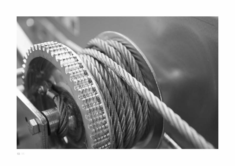
• Periodically lubricate the mechanisms with a light machine oil e.g. WD40 and check the cable for any signs of fraying. If cable damage is found, then cable should be replaced.
• If any parts need replacing, our aftersales department carry a comprehensive range of spares for overnight delivery.
• COMMON PART NUMBERS
P-WICA-2220-P-N – 1t winch cable P-WICA-2230-P-N – 1.5t winch cable P-WICA-2250-P-N – 2t winch cable S-WIPT-0260-P-N – Detachable winch handle S-WIPT-4201-P-N – Ratchet repair kit P-WIHK-1060-P-N – D Shackle

12 13
CHASSIS CARE AND PROTECTIONCARE AND PROTECTION OF YOUR NEW GALVANISED
CHASSIS TRAILER
PRODUCT INFORMATION All new Brian James Trailers feature, galvanised steel, aluminium and BZP plated steel components.
Materials and processes are designed to protect the structure of the trailer from corrosion. Eg: the formation of Iron Oxide on the steel. Galvanising is achieved by dipping the raw steel components into a bath of Zinc, usually at high temperature. The resultant coating on the steel is unlike any painted surface and will protect the steel for many years. Galvanising is however primarily a protective coating first and foremost.When new can appear reflective and bright, however after time will naturally change to a darker / blotchy appearance. During winter months when the roads are heavily salted there can be a noticeable hastening of this process. Combined with general road grime and soot this can cause a new trailer and its associated fixtures and fittings including aluminium and BZP plated components to change appearance.
Road salt or corrosive cleaning products left on the trailer will have no detrimental effect on the structure of the trailer in the long term, but may cause it and its components to begin to look weathered. In order to preserve the appearance of a new trailer as far as possible, it is advisable to rinse the trailer with clean water before leaving it to stand, especially during winter months.
CHASSIS CARE AND PROTECTION.
This is particularly advised when leaving a trailer inside a building, as there will be no natural rinsing from rain water. White patches of a powdery substance called Zinc Oxide may appear if the trailer is not prepared in this way. The effect can also arise on aluminium and BZP components. No detrimental operational effect will result from not taking care of the trailer according to these recommendations, this is purely an aesthetic issue.
Brian James Trailers will not accept liability for changes of surface appearance relating to galvanising, aluminium components or BZP plated components.
14 15
BRAKE ADJUSTMENT.
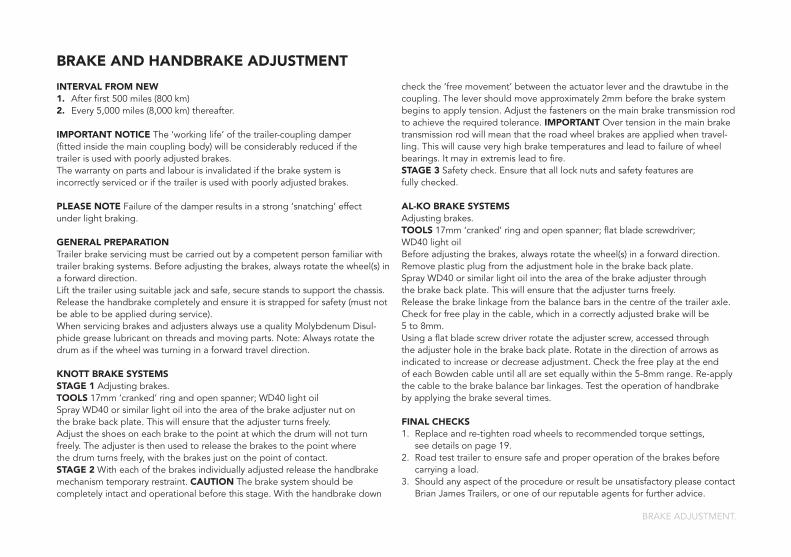
BRAKE AND HANDBRAKE ADJUSTMENT
INTERVAL FROM NEW1. After first 500 miles (800 km) 2. Every 5,000 miles (8,000 km) thereafter.
IMPORTANT NOTICE The ‘working life’ of the trailer-coupling damper (fitted inside the main coupling body) will be considerably reduced if the trailer is used with poorly adjusted brakes. The warranty on parts and labour is invalidated if the brake system is incorrectly serviced or if the trailer is used with poorly adjusted brakes.
PLEASE NOTE Failure of the damper results in a strong ‘snatching’ effect under light braking.
GENERAL PREPARATIONTrailer brake servicing must be carried out by a competent person familiar with trailer braking systems. Before adjusting the brakes, always rotate the wheel(s) in a forward direction.Lift the trailer using suitable jack and safe, secure stands to support the chassis.Release the handbrake completely and ensure it is strapped for safety (must not be able to be applied during service).When servicing brakes and adjusters always use a quality Molybdenum Disul-phide grease lubricant on threads and moving parts. Note: Always rotate the drum as if the wheel was turning in a forward travel direction.
KNOTT BRAKE SYSTEMSSTAGE 1 Adjusting brakes.TOOLS 17mm ‘cranked’ ring and open spanner; WD40 light oilSpray WD40 or similar light oil into the area of the brake adjuster nut on the brake back plate. This will ensure that the adjuster turns freely. Adjust the shoes on each brake to the point at which the drum will not turn freely. The adjuster is then used to release the brakes to the point where the drum turns freely, with the brakes just on the point of contact.STAGE 2 With each of the brakes individually adjusted release the handbrake mechanism temporary restraint. CAUTION The brake system should be completely intact and operational before this stage. With the handbrake down
check the ‘free movement’ between the actuator lever and the drawtube in the coupling. The lever should move approximately 2mm before the brake system begins to apply tension. Adjust the fasteners on the main brake transmission rod to achieve the required tolerance. IMPORTANT Over tension in the main brake transmission rod will mean that the road wheel brakes are applied when travel-ling. This will cause very high brake temperatures and lead to failure of wheel bearings. It may in extremis lead to fire.STAGE 3 Safety check. Ensure that all lock nuts and safety features are fully checked.
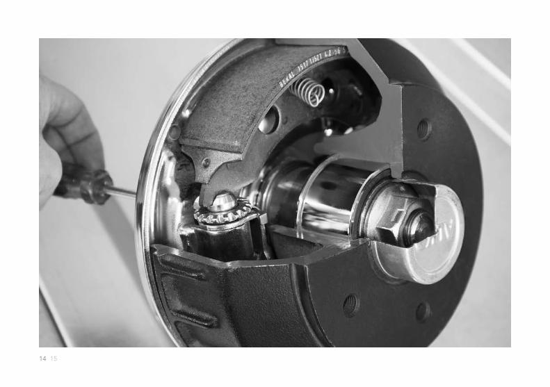
AL-KO BRAKE SYSTEMSAdjusting brakes. TOOLS 17mm ‘cranked’ ring and open spanner; flat blade screwdriver; WD40 light oilBefore adjusting the brakes, always rotate the wheel(s) in a forward direction.Remove plastic plug from the adjustment hole in the brake back plate. Spray WD40 or similar light oil into the area of the brake adjuster through the brake back plate. This will ensure that the adjuster turns freely.Release the brake linkage from the balance bars in the centre of the trailer axle. Check for free play in the cable, which in a correctly adjusted brake will be 5 to 8mm. Using a flat blade screw driver rotate the adjuster screw, accessed through the adjuster hole in the brake back plate. Rotate in the direction of arrows as indicated to increase or decrease adjustment. Check the free play at the end of each Bowden cable until all are set equally within the 5-8mm range. Re-apply the cable to the brake balance bar linkages. Test the operation of handbrake by applying the brake several times.
FINAL CHECKS1. Replace and re-tighten road wheels to recommended torque settings, see details on page 19.2. Road test trailer to ensure safe and proper operation of the brakes before carrying a load.3. Should any aspect of the procedure or result be unsatisfactory please contact Brian James Trailers, or one of our reputable agents for further advice.

16 17
COUPLING
NOTE Use trailer jockey wheel to lift and lower trailer to avoid injury.
Lift the coupling handle in the direction of the arrow. Some coupling designs such as the AL-KO type shown opposite will remain open. Having positioned the coupling above the towball now lower the trailer onto the towball until the ball engages into the head and is fully coupled. AL-KO coupling heads have a green indicator button to prove full coupling engagement.
UNCOUPLING
Pull the handle up as far as it will go and lift it from the towball. With larger nose loads, coupling and uncoupling can be made easier by using the jockey wheel to assist lifting.
SAFETY BALL
AL-KO recommends the fitment of a safety ball, this simple plastic ball fits inside the coupling head (whilst unhitched from the towball). Used in conjunction with a security device, the safety ball is locked into the coupling area, ensuring a thief cannot hitch your trailer to a smaller diameter towball or hook. This also acts as a very visual theft deterrent.
LUBRICATION
A small amount of standard grease should be applied to the towball to maintain a reduced friction environment.
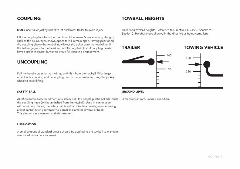
TOWBALL HEIGHTS
Trailer and towball heights. Reference to Directive EC 94/20, Annexe VII, Section 2. Height ranges allowed in the directive as being compliant.
TRAILER TOWING VEHICLE
GROUND LEVEL
Dimensions in mm. Loaded condition.
COUPLING.
465
395
420
350
18 19

WHEELS AND TYRESBOLT TORQUE TABLE AND TYRE PRESSURE CHART
TYRE PRESSURE CHART
RECOMMENDED TYRE PRESSURES
145/80 R10 2.5 bar (35 PSI) 195/55 R10 6.5 bar (90 PSI)
140/70 R12 4.25 bar (60 PSI) 155/70 R12 6.5 bar (90 PSI)
155/80 R13 2.5 bar (35 PSI) 165/80 R13 2.5 bar (35 PSI)
165/80 R13 8 ply 4.5 bar (65 PSI) 195/50 R13 6.5 bar (90 PSI)
RECOMMENDED TYRE PRESSURES on 155/70 R12 (capacity dependent)
2,000 kg gross capacity 3.0 bar (44 PSI)
2,600 kg gross capacity 4.2 bar (60 PSI)
3,000 kg gross capacity 5.0 bar (72 PSI)
HOW TO CHECK YOUR TYRES FOR SAFE TOWING OF TRAILERS
• Fit the correct tyres.• Tyres must be in good condition.• Tyre pressures must be correctly maintained using an accurate tyre pressure gauge.
WHEELS AND TYRES.
• Do not overload.• Check your tyres regularly for any signs of damage and remove from the tread any potential penetrations such as trapped stones.• Drive the combination at reasonable (‘comfortable’) speeds – within the speed limits.• Rapid manoeuvres must be avoided, e.g. sudden overtaking or lane changing. Good driving practice, with or without a trailer, includes intelligent anticipation of such moves.• Respect the car and trailer manufacturer’s recommendations at all times.
EU REGULATION (EC) NO 1222/2009
In November 2012, the new EU REGULATION (EC) No 1222/2009 sets out the labelling requirements of tyres with respect to fuel efficiency, wet grip and external rolling noises, aiming to increase safety, and the economic and environmental efficiency of road transport by promoting fuel-efficient and safe tyres with low noise levels. The Regulation shall apply from 1st November 2012. Tyre suppliers must monitor the labelling of C1, C2 and C3 tyres delivered to distributors and end-users.This labelling includes a sticker (see below) which must indicate:• The fuel efficiency class (letter A to G, A - the best, G - the worst. Otherwise known as rolling resistance). • The wet grip class (letter A to G); at this stage the Regulation only provides classification for wet grip performance for C1 tyres, but intends to introduce a classification for C2 tyres and eventually C3 tyres once tests are available; (Passenger cars are C1, light commercial vehicles are C2 and heavy commercial vehicles are C3).• The external rolling noise measured value (in decibels).
TORQUE TABLE
HT SET SCREWSWHEEL NUTS / BOLTS
TORQUE SETTING
M12 120 NM 89 ft/lb
M16 115 NM 85 ft/lb
ALLOY WHEELS 130 NM 96 ft/lb

20 21

TYRE RACK INSTRUCTIONS.
TYRE RACKIMPORTANT SAFETY INSTRUCTIONS FOR TYRE RACK
The tyre rack is designed to accommodate a wide range of different tyre sizes, and provides the ideal way to transport tyres and wheels safely whilst main- taining ease of operation of your Brian James Trailer.
IMPORTANT care must be taken when securing tyres, NEVER pull away or drive without first safely securing tyres with the appropriate tie-down straps.
The tyre rack is designed to hold the wheels between two parallel support bars, care should be taken to locate the tyre correctly. Always make sure the tyre tread area rests flat across the support bars as shown.
TO SECURE,
1. Position the tyre(s) between the two blue looped straps, making sure the straps are pushed up close to the tyre/wheel sides.
2. Attach the blue ratchet cross over strap to the middle of the first side loop strap, make sure the hook locates securely into the metal fixing bracket.
3. Position the strap over the top of the tyres, slide the two wide ‘strap protectors’ over the leading edge of each outer tyre.
4. Secure the ratchet end of the strap into the middle of the second cross over loop strap, make sure the hook locates securely into the metal fixing bracket.
5. Tighten the strap with the ratchet until secure, reverse the process to remove.
6. Always use Brian James Trailers strap system.
SECURITY *
To prevent theft, wheels and tyres can be locked in position. The locking system is made up of a high tensile steel cable and padlock. Follow the instructions to secure tyre/wheels as described. *Security cable also adds a second layer of cover, in the unlikely event of the main wheel strap working loose.
TO FIT,
1. Slide the looped part of the cable through the hole in the outer top section of the tyre rack frame, make sure the small back plate is on the OUTSIDE of this hole.
2. Pull the cable straight across and feed through the centre of the tyres/wheels.
3. Feed the cable through the hole in the far outer top section of the tyre rack frame.
4. Secure the cable (loop end) with a suitable padlock.

22 23
LIGHTING.
1
1
1
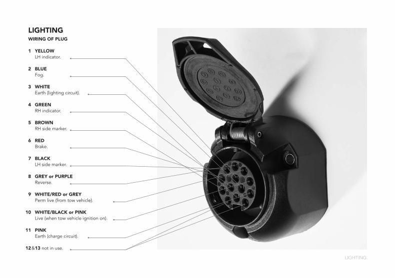
LIGHTINGWIRING OF PLUG
1 YELLOW LH indicator.
2 BLUE Fog.
3 WHITE Earth (lighting circuit).
4 GREEN RH indicator.
5 BROWN RH side marker.
6 RED Brake.
7 BLACK LH side marker.
8 GREY or PURPLE Reverse.
9 WHITE/RED or GREY Perm live (from tow vehicle).
0 WHITE/BLACK or PINK Live (when tow vehicle ignition on).
1 PINK Earth (charge circuit).
2 & 13 not in use.

24 25

WARRANTY
Every customer has the benefit of a unique five-year trailer chassis warranty, which protects against the failure of most technical components due to manufacturing defects. All warranty works must be completed by Brian James Trailers.
SERVICE EXPERTS
Regular servicing is key to safeguarding your trailer’s performance. Brian James Trailers offer a full maintenance and repair programme for owners to keep their valued trailers in fully working order.
Our trained staff and helpful service department management will ensure that your trailer enjoys the very best attention to detail, with particular emphasis on safety-critical matters.
In the event that a trailer is essential to operations we will always endeavour to provide a loan trailer to keep the wheels of your business turning while our team mend or service your trailer.
Our service department can be contacted on 01327 308837 direct or via our main switchboard on 01327 308833. E-mail us at [email protected]
HEAD OFFICE
In the heart of England, Brian James Trailers have been crafting an enviably diverse range of quality trailers for over thirty years since the company was formed in 1979.
Our opening times are Monday to Friday 8am – 6pm and Saturday 8am – 2pm.
Our head office can be contacted on 01327 308833. E-mail us at [email protected]
OUR ADDRESSBrian James Trailers Ltd. Sopwith Way, Drayton Fields Industrial Estate Daventry Northamptonshire NN11 8PB
Find more information on our website: www.brianjames.co.uk And our latest news and videos on Facebook and Youtube.
Registered in England & Wales No. 3844151 Registered Office: Central Chambers, 45-47 Albert Street, Rugby, CV21 2SG Vat Reg. No. GB 307 3660 71
BRIAN JAMES TRAILERS SERVICE.

26 27
GENUINE PARTS
You can rest assured, only genuine Brian James Trailers parts are used on your trailer.
Keeping your trailer running smoothly and efficiently is always at the forefront of our parts department’s mind. We work with diligence to provide an overnight service in most cases. Our parts department stock a wide variety of parts, some special parts can be manufactured to order.
Accessories are always popular ways of enhancing the functionality of your trailer to suit changing needs, a full array of options from extended mesh sides to winches are commonly available.
Visit the brochures and price lists section of our website to download the latest parts catalogue.
Our parts department can be contacted on 01327 308826 direct or via our main switchboard on 01327 308833. E-mail us at [email protected]
QUALITY
Brian James Trailers are manufacturers of class leading trailers. When you buy a Brian James Trailer you can be absolutely certain that it is designed, constructed and tested to the highest possible standards. Our Engineers combine top-quality craftsmanship with the best materials and first-class presentation. Light but strong, our trailers are crafted to enhance safety, efficiency and durability. Striving for perfection, nothing is left to chance, everything is considered.
IMPROVEMENT
Our team is dedicated to constantly refine our trailers. We continually gather feedback from our trained Technicians as well as our customers to ensure every trailer performs as it should – improving everything from its efficiency to its precision. You can have confidence in us.
COMMITMENT
We strongly believe in commitment. Our business is entirely dedicated to serving our customers and to ensuring the trailers we supply are fully compliant with all aspects of legal requirements. 2012 was an important year for the trailer industry in the UK and mainland Europe. From the 29th July 2012 every new trailer manufactured must be TYPE APPROVED for it to be legally used on the public highway. Not all manufacturers are ready to comply, Brian James Trailers are. After many years of work to achieve this BJT products have a full European Community Whole Vehicle Type Approval (ECWVTA).
BRIAN JAMES TRAILERS SERVICE.

Connected to you»
T +44 (0)1327 308 833For more information please call or visit our website.
Brian James Trailers Ltd.Sopwith Way, Drayton Fields Industrial EstateDaventry, Northants, NN11 8PB
www.brianjames.co.uk
Specifications are subject to change without notice.
© BRIAN JAMES TRAILERS. Printed in the UK.
Edition BJT2015-UK-OH01
THANK YOU.