Embed Size (px)
Citation preview
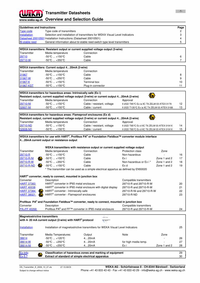
Overview and Selection Guide
Guidelines and Instructions
Type code Type code of transmitters
Installation Selection and installation of transmitters for WEKA Visual Level Indicators
Datasheet 20010501Installation Instructions (Datasheet 20010501)
Bi-stable reed General information about bi-stable reed-switch type level transmitters
WEKA transmitters: Resistant output or current supplied voltage output (3-wire)
Transmitter Media temperature Connection
29710 -50°C ... +150°C Cable
29710-W -50°C ... +350°C Cable
WEKA transmitters: Current output 4…20mA (2-wire)
Transmitter Media temperature Connection
31967 -50°C ... +150°C Cable
31967-W -50°C ... +250°C Cable
31967-K -50°C ... +150°C Terminal box
31967-KST -50°C ... +150°C Plug-in connector
WEKA transmitters for hazardous areas: Intrinsically safe (Ex i)
Resistant output, current supplied voltage output (3-wire) or current output 4…20mA (2-wire)
Transmitter Media temperature Connection Approval
29710-NI -50°C ... +150°C Cable / resistant, voltage II 2GD T85°C Ex ia IIC T6 ZELM 03 ATEX 0179
32607-NI -50°C ... +150°C Cable / current II 2GD T135°C Ex ia IIC T4 ZELM 03 ATEX 0168
WEKA transmitters for hazardous areas: Flameproof enclosures (Ex d)
Resistant output, current supplied voltage output (3-wire) or current output 4…20mA (2-wire)
Transmitter Media temperature Connection Approval
29710-ND -50°C ... +150°C Cable / resistant, voltage II 2GD T85°C Ex d IIC T6 ZELM 03 ATEX 0191X
32608-ND -50°C ... +150°C Cable / current II 2GD T85°C Ex d IIC T6 ZELM 03 ATEX 0191X
2
Page
14
Transmitter Datasheets-1-
4
10
11
7
8
15
9
3
5
12
13
6
32608-ND -50°C ... +150°C Cable / current II 2GD T85°C Ex d IIC T6 ZELM 03 ATEX 0191X
WEKA transmitters with resistance output or current supplied voltage output
Transmitter Media temperature Connection Protection class Zone
29710-R -50°C ... +150°C Cable Non-hazardous -
29710-R-NI -50°C ... +150°C Cable Ex i Zone 1 and 2
29710-R-W -50°C ... +350°C Cable Non-hazardous or Ex i * Zone 1 and 2
29710-R-ND -50°C ... +150°C Cable Ex d Zone 1 and 2
* The transmitter can be used as a simple electrical appartus as defined by EN50020
HART® converter, ready to connect, mounted in junction box
Converter Description Compatible transmitters
HART 37383 HART® converter in IP65 metal enclosure 29710-R and 29710-R-W
HART 40038 HART® converter in IP65 metal enclosure with digital display 29710-R and 29710-R-W
HART 37384 HART® converter - Intrinsically safe 29710-R-NI and 29710-R-W
HART 38021 HART® converter - Flameproof enclosures 29710-R-ND
Profibus PA® and Foundation Fieldbus™ converter, ready to connect, mounted in junction box
Converter Description Compatible transmitters
PA+FF 40268 Profibus PA® and FF™ converter in IP65 metal enclosure 29710-R and 29710-R-W
Magnetostrictive transmitters
with 4- 20 mA current output (2-wire) with HART® protocol
Installation Installation of magnetostrictive transmitters for WEKA Visual Level Indicators
Transmitter Media Temperatures: Output Note Zone
38614 -50°C ... +120°C 4…20mA -
38614-W -50°C ... +250°C 4…20mA for high media temp. -
38614-NI -50°C ... +250°C 4…20mA Ex i Zone 1 and 2
Ex-Info Classification of hazardous zones and marking of equipment
Ex-5.7 Extract of standard of simple electrical apparatus
24
22
29
25
27
28
26
WEKA transmitters for use with HART®, Profibus PA® or Foundation Fieldbus™ converter module interface
4…20mA current output or resistance output
21
15
19
16
30
23
17
18
20
Ex-5.7 Extract of standard of simple electrical apparatus
DS_Transmitter_E_2009_10_27.xls 27.10.09/Ot WEKA AG - Schürlistrasse 8 - CH-8344 Bäretswil - Switzerland
Subject to change without notice Phone +41 43 833 43 43 - Fax +41 43 833 43 29 - [email protected] - www.weka-ag.ch
30
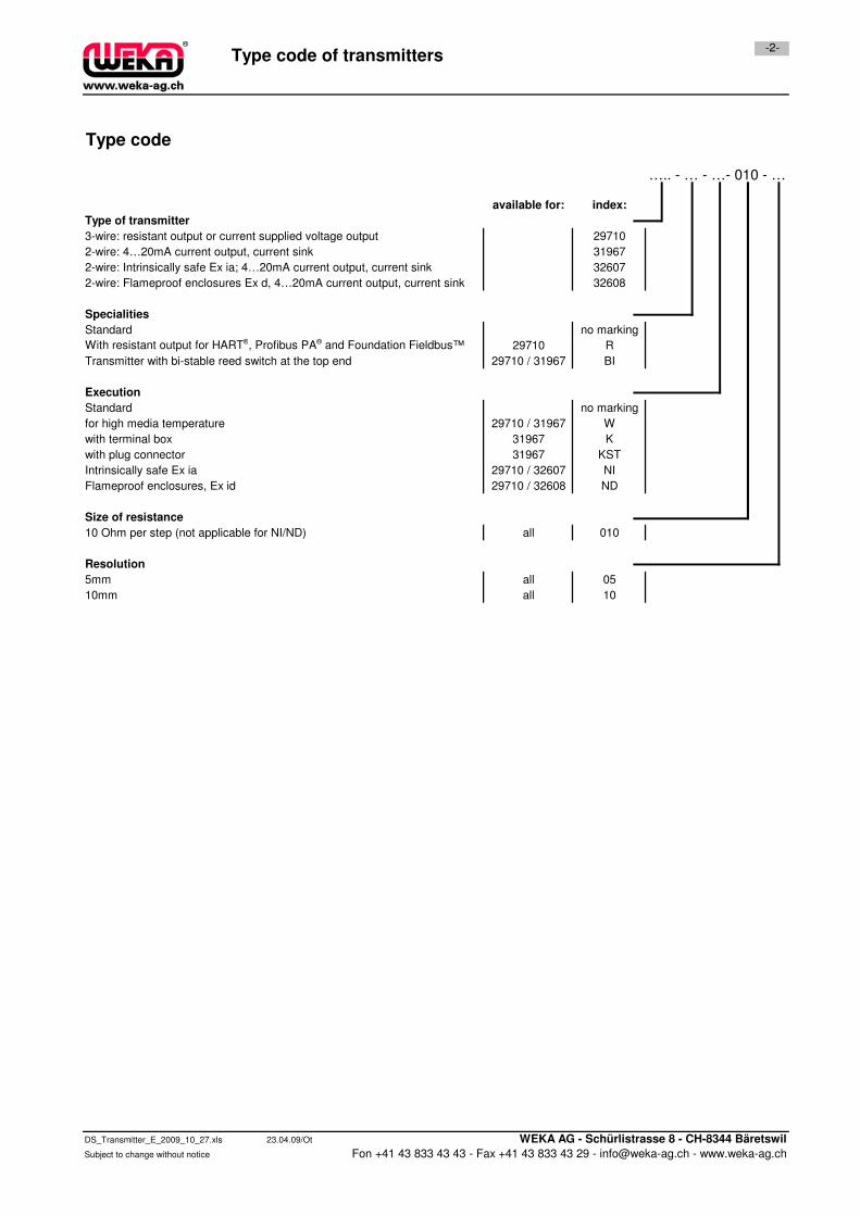
3-wire: resistant output or current supplied voltage output
With resistant output for HART®, Profibus PA® and Foundation Fieldbus™
Transmitter with bi-stable reed switch at the top end
2-wire: 4…20mA current output, current sink
2-wire: Intrinsically safe Ex ia; 4…20mA current output, current sink
Type code of transmitters-2-
Type code
….. - … - …- 010 - …
available for: index:
Specialities
Standard no marking
2-wire: Flameproof enclosures Ex d, 4…20mA current output, current sink
Type of transmitter
29710
31967
32607
29710 R
29710 / 31967 BI
32608
Execution
Standard no marking
for high media temperature 29710 / 31967 W
with terminal box 31967 K
with plug connector 31967 KST
Intrinsically safe Ex ia 29710 / 32607 NI
Flameproof enclosures, Ex id 29710 / 32608 ND
Size of resistance
10 Ohm per step (not applicable for NI/ND) all 010
05
10mm all 10
Resolution
5mm all
DS_Transmitter_E_2009_10_27.xls 23.04.09/Ot WEKA AG - Schürlistrasse 8 - CH-8344 Bäretswil
Subject to change without notice Fon +41 43 833 43 43 - Fax +41 43 833 43 29 - [email protected] - www.weka-ag.ch
Selection and Installation Instructions
-3-
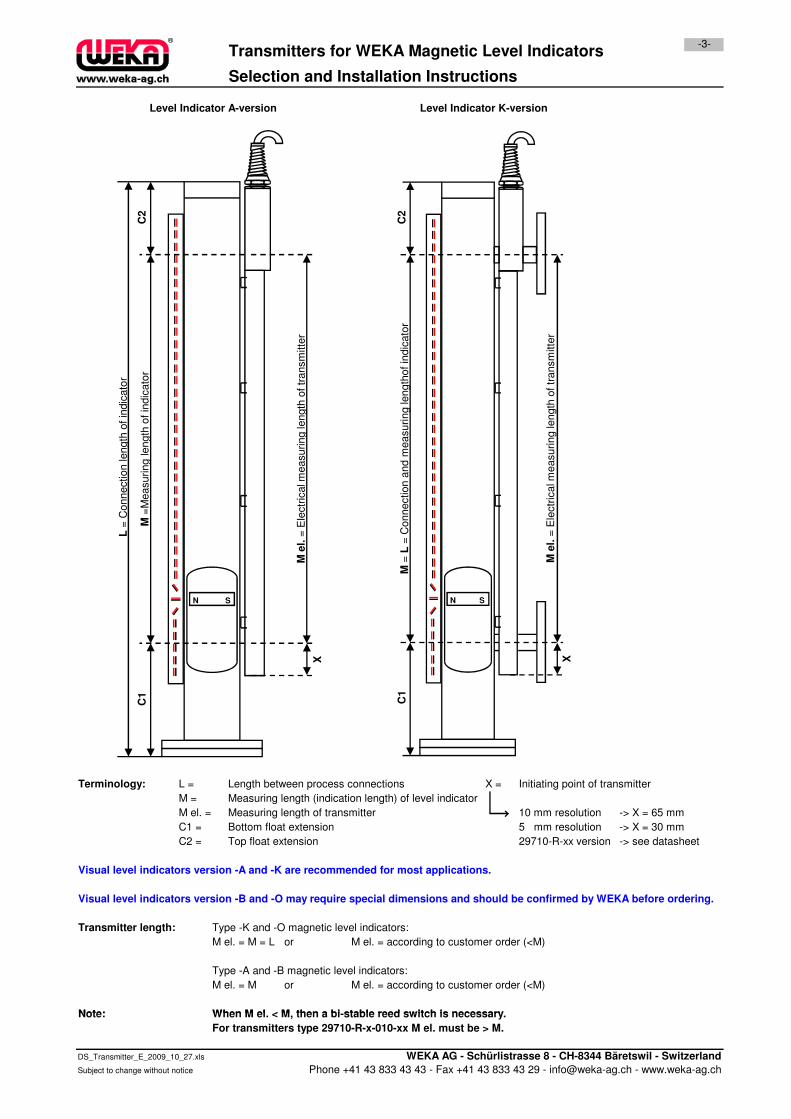
Level Indicator A-version Level Indicator K-version
Transmitters for WEKA Magnetic Level Indicators
= E
lectr
ical m
easuring le
ngth
of tr
ansm
itte
r
=M
easuring length
of in
dic
ato
r
= C
onnection length
of in
dic
ato
r
C2
= C
onnection a
nd m
easuring le
ngth
of in
dic
ato
r
= E
lectr
ical m
easuring le
ngth
of tr
ansm
itte
r
C2
Terminology: L = Length between process connections X = Initiating point of transmitter
M = Measuring length (indication length) of level indicator
M el. = Measuring length of transmitter 10 mm resolution -> X = 65 mm
C1 = Bottom float extension 5 mm resolution -> X = 30 mm
C2 = Top float extension 29710-R-xx version -> see datasheet
Transmitter length: Type -K and -O magnetic level indicators:
M el. = M = L or M el. = according to customer order (<M)
Type -A and -B magnetic level indicators:
M el. = M or M el. = according to customer order (<M)
Note: When M el. < M, then a bi-stable reed switch is necessary.
Visual level indicators version -A and -K are recommended for most applications.
Visual level indicators version -B and -O may require special dimensions and should be confirmed by WEKA before ordering.
M e
l.=
Ele
ctr
ical m
easuring le
ngth
of tr
ansm
itte
r
M =
Measuring length
of in
dic
ato
r
N S
L=
Connection length
of in
dic
ato
r
C1
X
M =
L=
Connection a
nd m
easuring le
ngth
of in
dic
ato
r
M e
l.=
Ele
ctr
ical m
easuring le
ngth
of tr
ansm
itte
r
N S
C1
X
Note: When M el. < M, then a bi-stable reed switch is necessary.
For transmitters type 29710-R-x-010-xx M el. must be > M.
DS_Transmitter_E_2009_10_27.xls WEKA AG - Schürlistrasse 8 - CH-8344 Bäretswil - Switzerland
Subject to change without notice Phone +41 43 833 43 43 - Fax +41 43 833 43 29 - [email protected] - www.weka-ag.ch
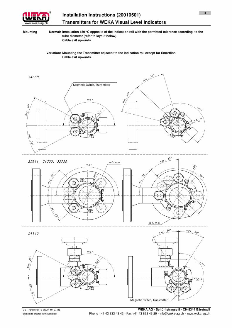
Mounting Normal:
Cable exit upwards.
Variation: Mounting the Transmitter adjacent to the indication rail except for Smartline.
Cable exit upwards.
Installation Instructions (20010501)-4-
Transmitters for WEKA Visual Level Indicators
Installation 180 °C opposite of the indication rail with the permitted tolerance according to the
tube diameter (refer to layout below)
Magnetic Switch, Transmitter
DS_Transmitter_E_2009_10_27.xls WEKA AG - Schürlistrasse 8 - CH-8344 Bäretswil
Subject to change without notice Phone +41 43 833 43 43 - Fax +41 43 833 43 29 - [email protected] - www.weka-ag.ch
Magnetic Switch, Transmitter
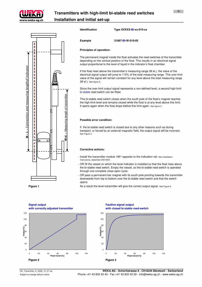
Installation and initial set-up
Principles of operation:
Possible error condition:
31967-Bi-W-010-05
Transmitters with high-limit bi-stable reed switches
Type XXXXX-Bi-xx-010-xx
If the bi-stable reed switch is closed due to any other reasons such as during
transport, or forced by an external magnetic field, the output signal will be incorrect.
-5-
The permanent magnet inside the float activates the reed switches of the transmitter
depending on the vertical position of the float. This results in an electrical signal
output proportional to the level of liquid in the indicator’s float chamber.
If the float rises above the transmitter’s measuring range (M el.), the value of the
electrical signal output will jump to 115% of the total measuring range. This over-limit
value of the signal will remain constant for any level above the total measuring range
(M el.). See figure 2.
Since the over-limit output signal represents a non-defined level, a second high-limit
bi-stable reed switch can be fitted.
This bi-stable reed switch closes when the south pole of the float’s magnet reaches
the high-limit level and remains closed while the float is at any level above this limit.
It opens again when the float drops bellow this limit again. See figure 2.
Identification
Example
= M
easuring length
of tr
ansm
itte
r
=C
on
ne
ctio
n a
nd
me
asu
rin
g l
en
gth
of
ind
ica
tor
Corrective actions:
-
-
-
Figure 1
Signal output Faultive signal output
with correctly adjusted transmitter with closed bi-stable reed-switch
Figure 2 Figure 3
OR pass a permanent bar magnet with its south pole pointing towards the transmitter
downwards from top to bottom over the bi-stable reed switch and that the switch
opens.
Install the transmitter module 180° opposite to the indication rail. See Installation
Instructions, datasheet 20010501.
OR fill the vessel on which the level indicator is installed so that the float rises above
the bi-stable reed switch. Empty the vessel, so the bi-stable reed switch is operated
through one complete close-open cycle.
As a result the level transmitter will give the correct output signal. See Figure 2.
transport, or forced by an external magnetic field, the output signal will be incorrect. See Figure 3.
0
20
40
60
80
100
120
0 20 40 60 80 100 120
Ou
tpu
t [%
]
Float travel [%]
0
20
40
60
80
100
120
0 20 40 60 80 100 120
Ou
tpu
t [%
]
Float travel [%]
M e
l.=
Measuring length
of tr
ansm
itte
r
M =
L=
N S
Figure 2 Figure 3
DS_Transmitter_E_2009_10_27.xls WEKA AG - Schürlistrasse 8 - CH-8344 Bäretswil - Switzerland
Subject to change without notice Phone +41 43 833 43 43 - Fax +41 43 833 43 29 - [email protected] - www.weka-ag.ch
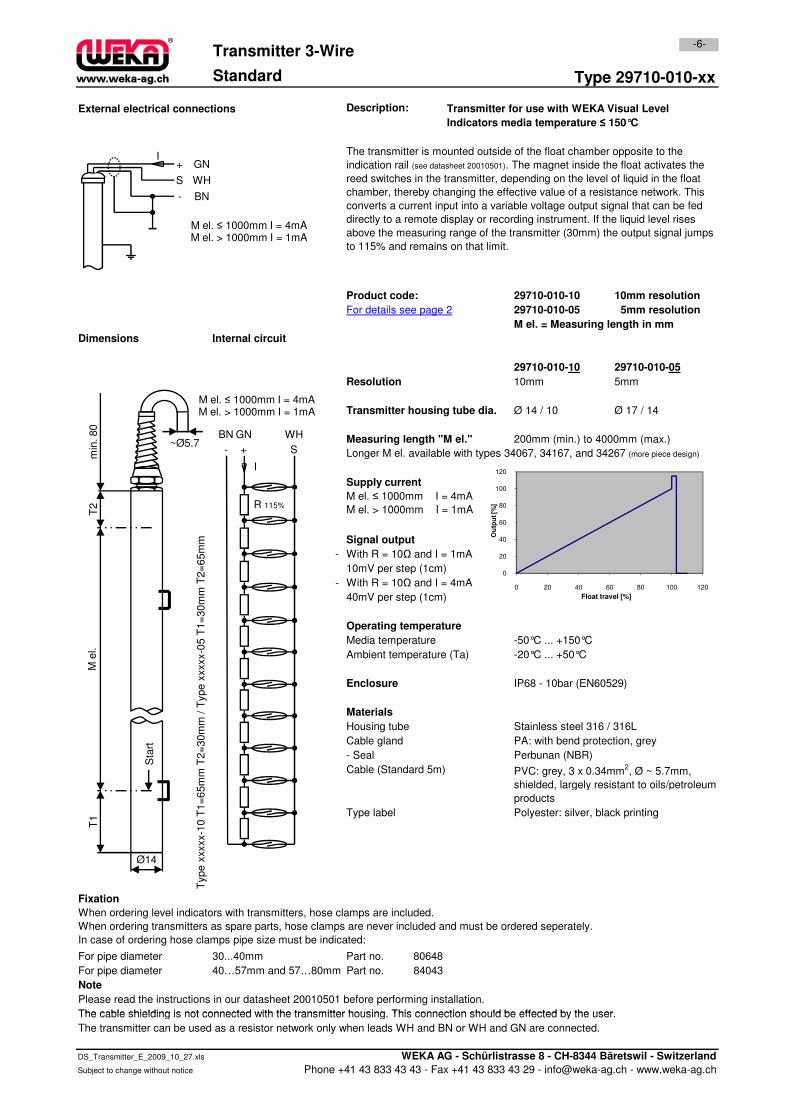
Type 29710-010-xx
External electrical connections Description:
29710-010-10 10mm resolution
29710-010-05 5mm resolution
M el. = Measuring length in mm
29710-010-10 29710-010-05
10mm 5mm
Transmitter housing tube dia. Ø 14 / 10 Ø 17 / 14
Measuring length "M el." 200mm (min.) to 4000mm (max.)
Longer M el. available with types 34067, 34167, and 34267 (more piece design)
Dimensions
Resolution
Supply current
For details see page 2
Transmitter for use with WEKA Visual Level
Indicators media temperature ≤ 150°C
The transmitter is mounted outside of the float chamber opposite to the
indication rail (see datasheet 20010501). The magnet inside the float activates the
reed switches in the transmitter, depending on the level of liquid in the float
chamber, thereby changing the effective value of a resistance network. This
converts a current input into a variable voltage output signal that can be fed
directly to a remote display or recording instrument. If the liquid level rises
above the measuring range of the transmitter (30mm) the output signal jumps
to 115% and remains on that limit.
Product code:
-6-Transmitter 3-Wire
Internal circuit
M el. ≤ 1000mm I = 4mA
M el. > 1000mm I = 1mA
Standard
80
100
120
Ou
tpu
t [%
]
- + S
BN GN WH
I
R 115%
+
M el. ≤ 1000mm I = 4mAM el. > 1000mm I = 1mA
S
-
GN
WH
BN
I
2m
in. 80
~Ø5,7
M el. ≤ 1000mm I = 4mAM el. > 1000mm I = 1mA
- With R = 10Ω and I = 1mA
10mV per step (1cm)
- With R = 10Ω and I = 4mA
40mV per step (1cm)
Media temperature -50°C ... +150°C
Ambient temperature (Ta) -20°C ... +50°C
IP68 - 10bar (EN60529)
Housing tube Stainless steel 316 / 316L
Cable gland PA: with bend protection, grey
- Seal Perbunan (NBR)
Cable (Standard 5m)
Type label Polyester: silver, black printing
Fixation
For pipe diameter 30...40mm Part no. 80648
For pipe diameter 40…57mm and 57…80mm Part no. 84043
Note
Please read the instructions in our datasheet 20010501 before performing installation.
The cable shielding is not connected with the transmitter housing. This connection should be effected by the user.
When ordering level indicators with transmitters, hose clamps are included.
When ordering transmitters as spare parts, hose clamps are never included and must be ordered seperately.
In case of ordering hose clamps pipe size must be indicated:
Signal output
Enclosure
PVC: grey, 3 x 0.34mm2, Ø ~ 5.7mm,
shielded, largely resistant to oils/petroleum
products
Operating temperature
Materials
M el. > 1000mm I = 1mA
Type x
xxxx-1
0 T
1=
65m
m T
2=
30m
m /
Type x
xxxx-0
5 T
1=
30m
m T
2=
65m
m
0
20
40
60
80
0 20 40 60 80 100 120
Ou
tpu
t [%
]
Float travel [%]
R 115%
T2
M e
l.T
1
Ø14
Sta
rt
The cable shielding is not connected with the transmitter housing. This connection should be effected by the user.
The transmitter can be used as a resistor network only when leads WH and BN or WH and GN are connected.
DS_Transmitter_E_2009_10_27.xls WEKA AG - Schürlistrasse 8 - CH-8344 Bäretswil - Switzerland
Subject to change without notice Phone +41 43 833 43 43 - Fax +41 43 833 43 29 - [email protected] - www.weka-ag.ch

Type 29710-W-010-xx
External electrical connections Description:
29710-W-010-10 10mm resolution
29710-W-010-05 5mm resolution
M el. = Measuring length in mm
29710-W-010-10 29710-W-010-05
10mm 5mm
Transmitter housing tube dia. Ø 14 / 10 Ø 17 / 14
Measuring length "M el." 200mm (min.) to 4000mm (max.)
Longer M el. available with types 34067, 34167, and 34267 (more piece design)
Dimensions
The transmitter is mounted outside of the float chamber opposite to the
indication rail (see datasheet 20010501). The magnet inside the float
activates the reed switches in the transmitter, depending on the level of liquid
in the float chamber, thereby changing the effective value of a resistance
network. This converts a current input into a variable voltage output signal that
can be fed directly to a remote display or recording instrument. If the liquid
level rises above the measuring range of the transmitter (30mm) the output
signal jumps to 115% and remains on that limit.
Internal circuit
Transmitter for use with WEKA Visual Level
Indicators media temperature ≤ 350°C
Product code:
For details see page 2
Supply current
-7-
Resolution
Transmitter 3-Wire
high Temperature
M el. ≤ 1000mm I = 4mA
M el. > 1000mm I = 1mA80
100
120
Ou
tpu
t [%
]
Mel. ≤ 1000mm I = 4mAMel. > 1000mm I = 1mA
- + S
BN GN/YE BU
I
R 115%
+L ≤ 1000mm I = 4mAL > 1000mm I = 1mAS
-
GN/YE
BU
BN
I+
L ≤ 1000mm I = 4mAL > 1000mm I = 1mAS
-
GN/YE
BU
BN
I
Mel. ≤ 1000mm I = 4mAMel. > 1000mm I = 1mA
T2
min
. 45
~Ø6,7
- With R = 10Ω and I = 1mA
10mV per step (1cm)
- With R = 10Ω and I = 4mA
40mV per step (1cm)
Media temperature -50°C ... +350°C
Ambient temperature (Ta) -20°C ... +50°C
IP68 - 10bar (EN60529)
Housing tube Stainless steel 316 / 316L
Cable gland Brass: nickel plated
- Seal FKM / Fluoroelastomere
Cable (Standard 5m)
Type label Polyester: silver, black printing
Fixation
For pipe diameter 30...40mm Part no. 80648
For pipe diameter 40…57mm and 57…80mm Part no. 84043
Note
Please read the instructions in our datasheet 20010501 before performing installation.
The transmitter can be used as a resistor network only when leads BU and BN or BU and GN/YE are connected.
When ordering level indicators with transmitters, hose clamps are included.
When ordering transmitters as spare parts, hose clamps are never included and must be ordered seperately.
In case of ordering hose clamps pipe size must be indicated:
Enclosure
Type x
xxxx-1
0 T
1=
65m
m T
2=
30m
m /
Type x
xxxx-0
5 T
1=
30m
m T
2=
65m
m
Silicone: red, 3 x 0.75mm2, Ø ~ 6.7mm,
largely resistant to oils/petroleum products
Materials
Operating temperature
Signal output
M el. > 1000mm I = 1mA
0
20
40
60
80
0 20 40 60 80 100 120
Ou
tpu
t [%
]
Float travel [%]
R 115%TT
1
Ø14
Sta
rt
M e
l.
The transmitter can be used as a resistor network only when leads BU and BN or BU and GN/YE are connected.
DS_Transmitter_E_2009_10_27.xls WEKA AG - Schürlistrasse 8 - CH-8344 Bäretswil - Switzerland
Subject to change without notice Phone +41 43 833 43 43 - Fax +41 43 833 43 29 - [email protected] - www.weka-ag.ch
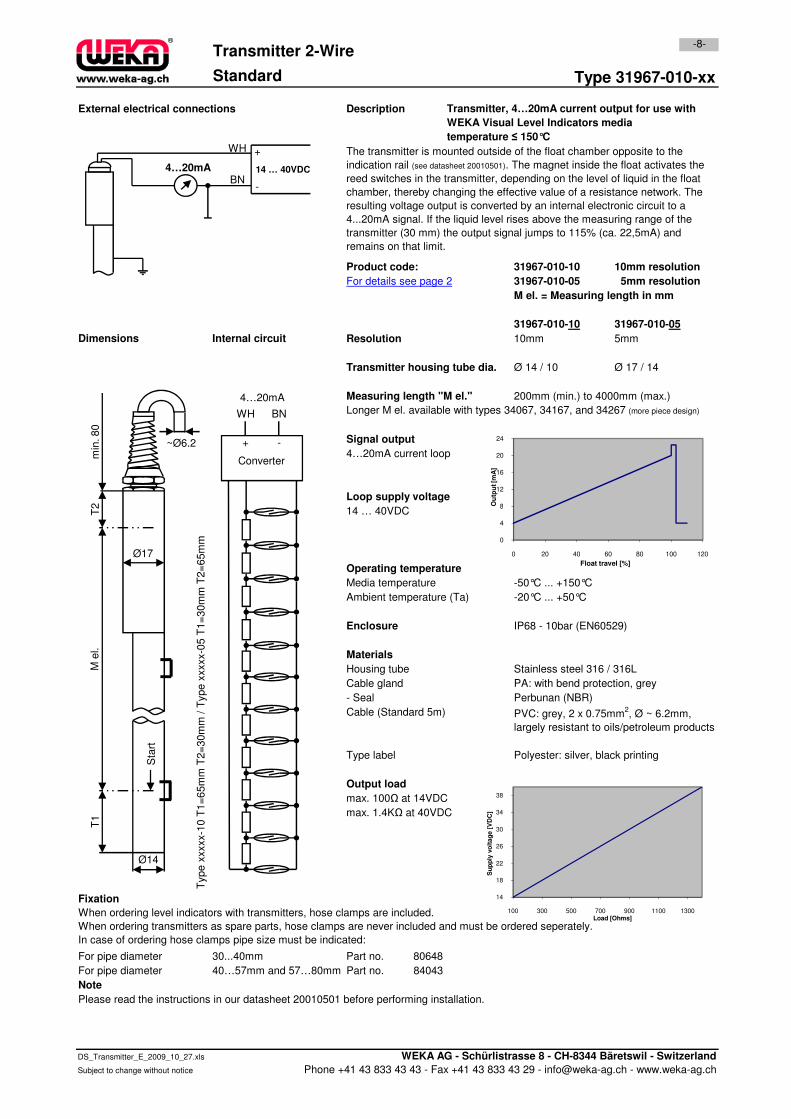
Type 31967-010-xx
External electrical connections Description
31967-010-10 10mm resolution
31967-010-05 5mm resolution
M el. = Measuring length in mm
31967-010-10 31967-010-05
10mm 5mm
Transmitter housing tube dia. Ø 14 / 10 Ø 17 / 14
Measuring length "M el." 200mm (min.) to 4000mm (max.)
Longer M el. available with types 34067, 34167, and 34267 (more piece design)
Signal output
4…20mA current loop
Loop supply voltage
14 … 40VDC
Transmitter, 4…20mA current output for use with
WEKA Visual Level Indicators media
temperature ≤ 150°C
The transmitter is mounted outside of the float chamber opposite to the
indication rail (see datasheet 20010501). The magnet inside the float activates the
reed switches in the transmitter, depending on the level of liquid in the float
chamber, thereby changing the effective value of a resistance network. The
resulting voltage output is converted by an internal electronic circuit to a
4...20mA signal. If the liquid level rises above the measuring range of the
transmitter (30 mm) the output signal jumps to 115% (ca. 22,5mA) and
remains on that limit.
-8-Transmitter 2-Wire
Standard
Resolution
Product code:
Internal circuitDimensions
For details see page 2
Converter
BNWH
-+
4…20mA
8
12
16
20
24
Ou
tpu
t [m
A]
2m
in. 80
~Ø6,2
4…20mA
WH
BN
+
-
14 … 40VDC
14 … 40VDC
Media temperature -50°C ... +150°C
Ambient temperature (Ta) -20°C ... +50°C
IP68 - 10bar (EN60529)
Housing tube Stainless steel 316 / 316L
Cable gland PA: with bend protection, grey
- Seal Perbunan (NBR)
Cable (Standard 5m)
Type label Polyester: silver, black printing
Output load
max. 100Ω at 14VDC
max. 1.4KΩ at 40VDC
Fixation
For pipe diameter 30...40mm Part no. 80648
For pipe diameter 40…57mm and 57…80mm Part no. 84043
Note
Please read the instructions in our datasheet 20010501 before performing installation.
PVC: grey, 2 x 0.75mm2, Ø ~ 6.2mm,
largely resistant to oils/petroleum products
Type x
xxxx-1
0 T
1=
65m
m T
2=
30m
m /
Type x
xxxx-0
5 T
1=
30m
m T
2=
65m
m
When ordering level indicators with transmitters, hose clamps are included.
When ordering transmitters as spare parts, hose clamps are never included and must be ordered seperately.
In case of ordering hose clamps pipe size must be indicated:
Operating temperature
Enclosure
Materials
0
4
8
0 20 40 60 80 100 120
Ou
tpu
t [m
A]
Float travel [%]
14
18
22
26
30
34
38
100 300 500 700 900 1100 1300
Su
pp
ly v
olt
ag
e [
VD
C]
Load [Ohms]
T2
M e
l.T
1
Ø14
Ø17
Sta
rt
DS_Transmitter_E_2009_10_27.xls WEKA AG - Schürlistrasse 8 - CH-8344 Bäretswil - Switzerland
Subject to change without notice Phone +41 43 833 43 43 - Fax +41 43 833 43 29 - [email protected] - www.weka-ag.ch
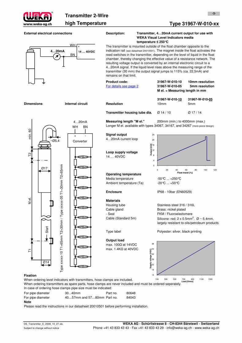
Type 31967-W-010-xx
External electrical connections Description:
31967-W-010-10 10mm resolution
31967-W-010-05 5mm resolution
M el. = Measuring length in mm
31967-W-010-10 31967-W-010-05
10mm 5mm
Transmitter housing tube dia. Ø 14 / 10 Ø 17 / 14
Measuring length "M el." 200mm (min.) to 4000mm (max.)
Longer M el. available with types 34067, 34167, and 34267 (more piece design)
Signal output
4…20mA current loop
Loop supply voltage
14 … 40VDC
ResolutionDimensions Internal circuit
The transmitter is mounted outside of the float chamber opposite to the
indication rail (see datasheet 20010501). The magnet inside the float activates the
reed switches in the transmitter, depending on the level of liquid in the float
chamber, thereby changing the effective value of a resistance network. The
resulting voltage output is converted by an internal electronic circuit to a
4...20mA signal. If the liquid level rises above the measuring range of the
transmitter (30 mm) the output signal jumps to 115% (ca. 22,5mA) and
remains on that limit.
Product code:
For details see page 2
-9-Transmitter 2-Wire
high Temperature
Transmitter, 4…20mA current output for use with
WEKA Visual Level Indicators media
temperature ≤ 250°C
Converter
BNWH
-+
4…20mA
8
12
16
20
24
Ou
tpu
t [m
A]
T2
min
. 60
~Ø5,4
4…20mA
WH
BN
+
-
14 … 40VDC
14 … 40VDC
Media temperature -50°C ... +250°C
Ambient temperature (Ta) -20°C ... +50°C
IP68 - 10bar (EN60529)
Housing tube Stainless steel 316 / 316L
Cable gland Brass: nickel plated
- Seal FKM / Fluoroelastomere
Cable (Standard 5m)
Type label Polyester: silver, black printing
Output load
max. 100Ω at 14VDC
max. 1.4KΩ at 40VDC
Fixation
For pipe diameter 30...40mm Part no. 80648
For pipe diameter 40…57mm and 57…80mm Part no. 84043
Note
Please read the instructions in our datasheet 20010501 before performing installation.
Enclosure
Operating temperature
When ordering level indicators with transmitters, hose clamps are included.
When ordering transmitters as spare parts, hose clamps are never included and must be ordered seperately.
In case of ordering hose clamps pipe size must be indicated:
Materials
Type x
xxxx-1
0 T
1=
65m
m T
2=
30m
m /
Type x
xxxx-0
5 T
1=
30m
m T
2=
65m
m
Silicone: red; 2 x 0.5mm2, Ø ~ 5.4mm,
largely resistant to oils/petroleum products
0
4
8
0 20 40 60 80 100 120
Ou
tpu
t [m
A]
Float travel [%]
14
18
22
26
30
34
38
100 300 500 700 900 1100 1300
Su
pp
ly v
olt
ag
e [
VD
C]
Load [Ohms]
TM
el.
T1
Ø14
Ø17
Sta
rt
DS_Transmitter_E_2009_10_27.xls WEKA AG - Schürlistrasse 8 - CH-8344 Bäretswil - Switzerland
Subject to change without notice Phone +41 43 833 43 43 - Fax +41 43 833 43 29 - [email protected] - www.weka-ag.ch
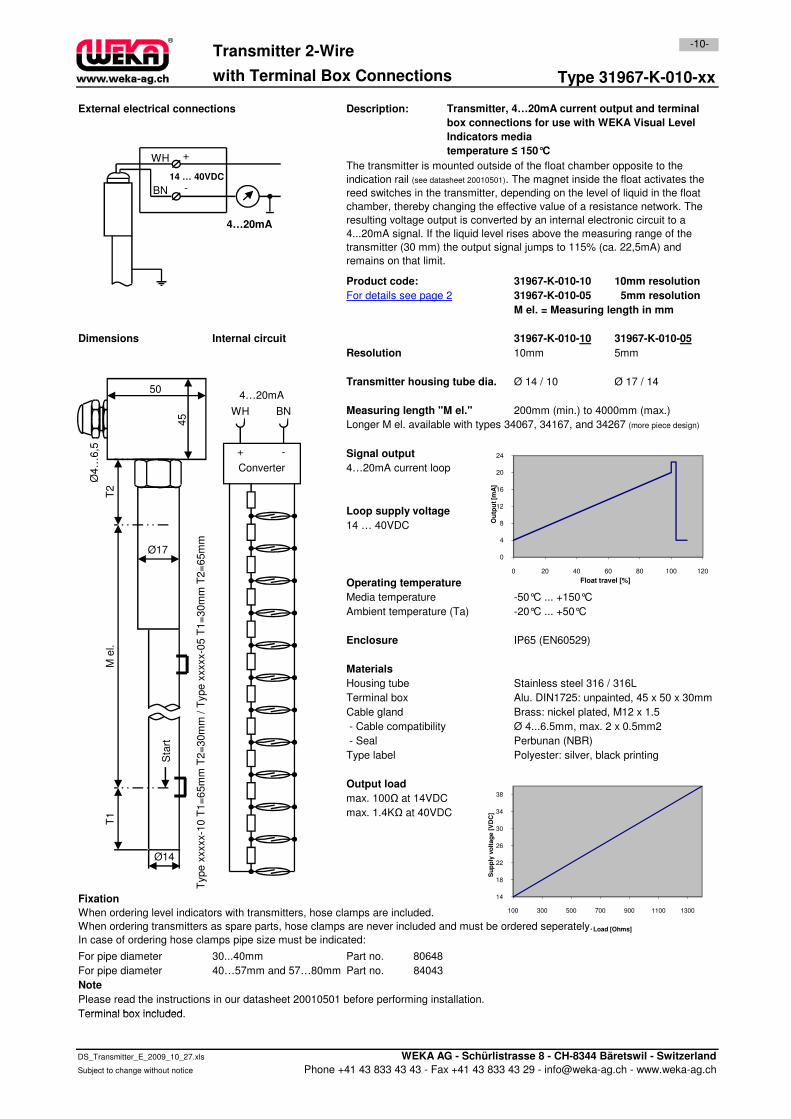
Type 31967-K-010-xx
External electrical connections Description:
31967-K-010-10 10mm resolution
31967-K-010-05 5mm resolution
M el. = Measuring length in mm
31967-K-010-10 31967-K-010-05
10mm 5mm
Transmitter housing tube dia. Ø 14 / 10 Ø 17 / 14
Measuring length "M el." 200mm (min.) to 4000mm (max.)
Longer M el. available with types 34067, 34167, and 34267 (more piece design)
Signal output
4…20mA current loop
Loop supply voltage
Internal circuit
-10-Transmitter 2-Wire
with Terminal Box Connections
The transmitter is mounted outside of the float chamber opposite to the
indication rail (see datasheet 20010501). The magnet inside the float activates the
reed switches in the transmitter, depending on the level of liquid in the float
chamber, thereby changing the effective value of a resistance network. The
resulting voltage output is converted by an internal electronic circuit to a
4...20mA signal. If the liquid level rises above the measuring range of the
transmitter (30 mm) the output signal jumps to 115% (ca. 22,5mA) and
remains on that limit.
For details see page 2
Transmitter, 4…20mA current output and terminal
box connections for use with WEKA Visual Level
Indicators media
temperature ≤ 150°C
Dimensions
Product code:
Resolution
12
16
20
24
Ou
tpu
t [m
A]
Converter
BNWH
-+
4…20mA
4…20mA
WH
BN
+
14 … 40VDC
-
T2
45
50
Ø4…
6,5
Loop supply voltage
14 … 40VDC
Media temperature -50°C ... +150°C
Ambient temperature (Ta) -20°C ... +50°C
IP65 (EN60529)
Housing tube Stainless steel 316 / 316L
Terminal box Alu. DIN1725: unpainted, 45 x 50 x 30mm
Cable gland Brass: nickel plated, M12 x 1.5
- Cable compatibility Ø 4...6.5mm, max. 2 x 0.5mm2
- Seal Perbunan (NBR)
Type label Polyester: silver, black printing
Output load
max. 100Ω at 14VDC
max. 1.4KΩ at 40VDC
Fixation
For pipe diameter 30...40mm Part no. 80648
For pipe diameter 40…57mm and 57…80mm Part no. 84043
Note
Please read the instructions in our datasheet 20010501 before performing installation.
Terminal box included.
When ordering level indicators with transmitters, hose clamps are included.
When ordering transmitters as spare parts, hose clamps are never included and must be ordered seperately.
In case of ordering hose clamps pipe size must be indicated:
Type x
xxxx-1
0 T
1=
65m
m T
2=
30m
m /
Type x
xxxx-0
5 T
1=
30m
m T
2=
65m
m
Operating temperature
Enclosure
Materials
0
4
8
12
0 20 40 60 80 100 120
Ou
tpu
t [m
A]
Float travel [%]
14
18
22
26
30
34
38
100 300 500 700 900 1100 1300
Su
pp
ly v
olt
ag
e [
VD
C]
Load [Ohms]
M e
l.T
1
Ø14
Ø17
Sta
rt
Terminal box included.
DS_Transmitter_E_2009_10_27.xls WEKA AG - Schürlistrasse 8 - CH-8344 Bäretswil - Switzerland
Subject to change without notice Phone +41 43 833 43 43 - Fax +41 43 833 43 29 - [email protected] - www.weka-ag.ch
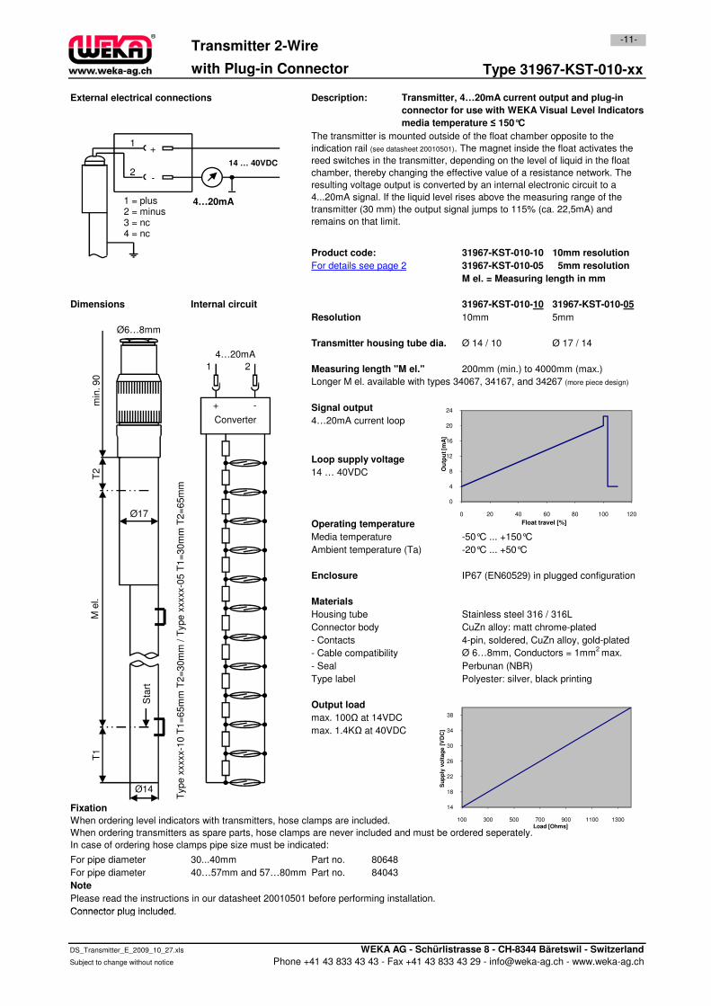
with Plug-in Connector Type 31967-KST-010-xx
External electrical connections Description:
31967-KST-010-10 10mm resolution
31967-KST-010-05 5mm resolution
M el. = Measuring length in mm
31967-KST-010-10 31967-KST-010-05
10mm 5mm
Transmitter housing tube dia. Ø 14 / 10 Ø 17 / 14
Measuring length "M el." 200mm (min.) to 4000mm (max.)
Longer M el. available with types 34067, 34167, and 34267 (more piece design)
Signal output
4…20mA current loop
Loop supply voltage
Product code:
Resolution
Dimensions Internal circuit
For details see page 2
-11-Transmitter 2-Wire
Transmitter, 4…20mA current output and plug-in
connector for use with WEKA Visual Level Indicators
media temperature ≤ 150°C
The transmitter is mounted outside of the float chamber opposite to the
indication rail (see datasheet 20010501). The magnet inside the float activates the
reed switches in the transmitter, depending on the level of liquid in the float
chamber, thereby changing the effective value of a resistance network. The
resulting voltage output is converted by an internal electronic circuit to a
4...20mA signal. If the liquid level rises above the measuring range of the
transmitter (30 mm) the output signal jumps to 115% (ca. 22,5mA) and
remains on that limit.
12
16
20
24
Ou
tpu
t [m
A]
Converter
21
-+
4…20mA
min
. 90
Ø6…8mm
4…20mA
1
2
+
14 … 40VDC
-
1 = plus2 = minus3 = nc4 = nc
Loop supply voltage
14 … 40VDC
Media temperature -50°C ... +150°C
Ambient temperature (Ta) -20°C ... +50°C
IP67 (EN60529) in plugged configuration
Housing tube Stainless steel 316 / 316L
Connector body CuZn alloy: matt chrome-plated
- Contacts 4-pin, soldered, CuZn alloy, gold-plated
- Cable compatibility Ø 6…8mm, Conductors = 1mm2
max.
- Seal Perbunan (NBR)
Type label Polyester: silver, black printing
Output load
max. 100Ω at 14VDC
max. 1.4KΩ at 40VDC
Fixation
For pipe diameter 30...40mm Part no. 80648
For pipe diameter 40…57mm and 57…80mm Part no. 84043
Note
Please read the instructions in our datasheet 20010501 before performing installation.
Connector plug included.
When ordering level indicators with transmitters, hose clamps are included.
When ordering transmitters as spare parts, hose clamps are never included and must be ordered seperately.
In case of ordering hose clamps pipe size must be indicated:
Type x
xxxx-1
0 T
1=
65m
m T
2=
30m
m /
Type x
xxxx-0
5 T
1=
30m
m T
2=
65m
m
Operating temperature
Enclosure
Materials
0
4
8
12
0 20 40 60 80 100 120
Ou
tpu
t [m
A]
Float travel [%]
14
18
22
26
30
34
38
100 300 500 700 900 1100 1300
Su
pp
ly v
olt
ag
e [
VD
C]
Load [Ohms]
T2
M e
l.T
1
Ø14
Ø17
Sta
rt
Connector plug included.
DS_Transmitter_E_2009_10_27.xls WEKA AG - Schürlistrasse 8 - CH-8344 Bäretswil - Switzerland
Subject to change without notice Phone +41 43 833 43 43 - Fax +41 43 833 43 29 - [email protected] - www.weka-ag.ch
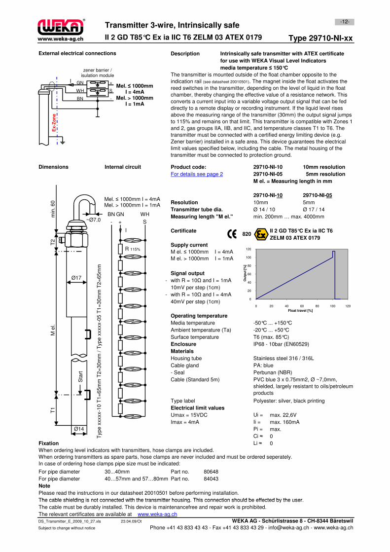
Description Intrinsically safe transmitter with ATEX certificate
for use with WEKA Visual Level Indicators
media temperature ≤ 150°C
29710-NI-10 10mm resolution
29710-NI-05 5mm resolution
M el. = Measuring length in mm
29710-NI-10 29710-NI-05
10mm 5mm
Transmitter tube dia. Ø 14 / 10 Ø 17 / 14
Measuring length "M el."
Certificate II 2 GD T85°C Ex ia IIC T6
ZELM 03 ATEX 0179
Type 29710-NI-xx
820
The transmitter is mounted outside of the float chamber opposite to the
indication rail (see datasheet 20010501). The magnet inside the float activates the
reed switches in the transmitter, depending on the level of liquid in the float
chamber, thereby changing the effective value of a resistance network. This
converts a current input into a variable voltage output signal that can be fed
directly to a remote display or recording instrument. If the liquid level rises
above the measuring range of the transmitter (30mm) the output signal jumps
to 115% and remains on that limit. This transmitter is compatible with Zones 1
and 2, gas groups IIA, IIB, and IIC, and temperature classes T1 to T6. The
transmitter must be connected with a certified energy limiting device (e.g.
Zener barrier) installed in a safe area. This device guarantees the electrical
limit values specified below, including the cable. The metal housing of the
transmitter must be connected to protection ground.
II 2 GD T85°C Ex ia IIC T6 ZELM 03 ATEX 0179
Dimensions
Supply current
M el. ≤ 1000mm I = 4mA
Product code:
Resolution
For details see page 2
-12-
min. 200mm … max. 4000mm
Transmitter 3-wire, Intrinsically safe
External electrical connections
Internal circuit
120
Mel. ≤ 1000mm I = 4mAMel. > 1000mm I = 1mA
- + S
BN GN WH
I
R 115%
+Mel. ≤ 1000mm
I = 4mAMel. > 1000mm
I = 1mA
S
-
GN
WH
BN
I
Ex-Z
on
e
zener barrier / isulation module
T2
min
. 60
~Ø7,0
- with R = 10Ω and I = 1mA
10mV per step (1cm)
- with R = 10Ω and I = 4mA
40mV per step (1cm)
Media temperature -50°C ... +150°C
Ambient temperature (Ta) -20°C ... +50°C
Surface temperature T6 (max. 85°C)
IP68 - 10bar (EN60529)
Housing tube Stainless steel 316 / 316L
Cable gland PA: blue
- Seal Perbunan (NBR)
Cable (Standard 5m)
Type label Polyester: silver, black printing
Electrical limit values
Umax = 15VDC Ui =
Imax = 4mA Ii =
Pi =
Ci ≈
Fixation Li ≈
For pipe diameter 30...40mm Part no. 80648
For pipe diameter 40…57mm and 57…80mm Part no. 84043
Please read the instructions in our datasheet 20010501 before performing installation.
The cable shielding is not connected with the transmitter housing. This connection should be effected by the user.
When ordering level indicators with transmitters, hose clamps are included.
When ordering transmitters as spare parts, hose clamps are never included and must be ordered seperately.
In case of ordering hose clamps pipe size must be indicated:
max.
0
0
max. 160mA
PVC blue 3 x 0.75mm2, Ø ~7,0mm,
shielded, largely resistant to oils/petroleum
products
Note
Signal output
Operating temperature
Enclosure
M el. ≤ 1000mm I = 4mA
M el. > 1000mm I = 1mA
Type x
xxxx-1
0 T
1=
65m
m T
2=
30m
m /
Type x
xxxx-0
5 T
1=
30m
m T
2=
65m
m
max. 22,6V
Materials
0
20
40
60
80
100
120
0 20 40 60 80 100 120
Ou
tpu
t [%
]
Float travel [%]
R 115%
M e
l.T
1
Ø14
Ø17
Sta
rt
The cable shielding is not connected with the transmitter housing. This connection should be effected by the user.
The cable must be durably installed. This device is maintenancefree and repair work is prohibited.
The relevant certificates are available at www.weka-ag.ch
DS_Transmitter_E_2009_10_27.xls 23.04.09/Ot WEKA AG - Schürlistrasse 8 - CH-8344 Bäretswil
Subject to change without notice Phone +41 43 833 43 43 - Fax +41 43 833 43 29 - [email protected] - www.weka-ag.ch
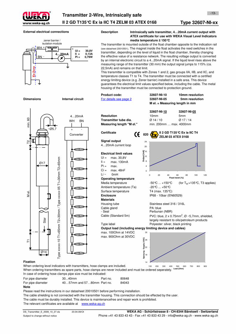
Type 32607-NI-xx
Description
32607-NI-10 10mm resolution
32607-NI-05 5mm resolution
M el. = Measuring length in mm
32607-NI-10 32607-NI-05
10mm 5mm
Transmitter tube dia. Ø 14 / 10 Ø 17 / 14
Measuring length "M el."
Certificate II 2 GD T135°C Ex ia IIC T4
ZELM 03 ATEX 0168
Signal output
4…20mA current loop
820
-13-
min. 200mm … max. 4000mm
Transmitter 2-Wire, Intrinsically safe
Resolution
Product code:
External electrical connections Intrinsically safe transmitter, 4…20mA current output with
ATEX certificate for use with WEKA Visual Level Indicators
media temperature ≤ 150°C
The transmitter is mounted outside of the float chamber opposite to the indication rail
(see datasheet 20010501). The magnet inside the float activates the reed switches in the
transmitter, depending on the level of liquid in the float chamber, thereby changing
the effective value of a resistance network. The resulting voltage output is converted
by an internal electronic circuit to a 4...20mA signal. If the liquid level rises above the
measuring range of the transmitter (30 mm) the output signal jumps to 115% (ca.
22,5mA) and remains on that limit.
This transmitter is compatible with Zones 1 and 2, gas groups IIA, IIB, and IIC, and
temperature classes T1 to T4. The transmitter must be connected with a certified
energy limiting device (e.g. Zener barrier) installed in a safe area. This device
guarantees the electrical limit values specified below, including the cable. The metal
housing of the transmitter must be connected to protection ground.
For details see page 2
II 2 GD T135°C Ex ia IIC T4 ZELM 03 ATEX 0168
Dimensions Internal circuit
Converter
BNWH
-+
4…20mA
16
20
24O
utp
ut
[mA
]
T2
min
. 60
~Ø5,7
4…20mA
WH
BN
+
-
30,8V0,13A0,79W
Ui = Ii = Pi =
+
-
Ex
-Zo
ne
zener barrier / isulation module
Electrical limit values
Ui =
Ii =
Pi =
Ci =
Li ~
Media temperature -50°C ... +150°C (for TM >135°C, T3 applies)
Ambient temperature (Ta) -20°C ... +50°C
Surface temperature T4 (max. 135°C)
IP68 - 10bar (EN60529)
Housing tube Stainless steel 316 / 316L
Cable gland PA: blue- Seal Perbunan (NBR)
Cable (Standard 5m)
Type label Polyester: silver, black printing
Output load (including energy limiting device and cables)
max. 100Ohm at 14VDC
max. 900Ohm at 30VDC
Fixation
For pipe diameter 30...40mm Part no. 80648
For pipe diameter 40…57mm and 57…80mm Part no. 84043
Please read the instructions in our datasheet 20010501 before performing installation.
The cable shielding is not connected with the transmitter housing. This connection should be effected by the user.
The cable must be durably installed. This device is maintenancefree and repair work is prohibited.
The relevant certificates are available at www.weka-ag.ch
When ordering level indicators with transmitters, hose clamps are included.
When ordering transmitters as spare parts, hose clamps are never included and must be ordered seperately.
In case of ordering hose clamps pipe size must be indicated:
PVC: blue, 2 x 0.75mm2, Ø ~5,7mm, shielded,
largely resistant to oils/petroleum products
Note
Operating temperature
Type x
xxxx-1
0 T
1=
65m
m T
2=
30m
m / T
ype x
xxxx-0
5 T
1=
30m
m T
2=
65m
m
0mH
Enclosure
Materials
max.
max. 30,8V
max. 130mA
max. 48nF 0
4
8
12
16
0 20 40 60 80 100 120
Ou
tpu
t [m
A]
Float travel [%]
14
18
22
26
30
100 200 300 400 500 600 700 800 900
Sp
eis
un
g /
Su
pp
ly [
VD
C]
Load [Ohm]
M e
l.T
1
Ø14
Ø17
Sta
r
The relevant certificates are available at www.weka-ag.ch
DS_Transmitter_E_2009_10_27.xls 23.04.09/Ot WEKA AG - Schürlistrasse 8 - CH-8344 Bäretswil - Switzerland
Subject to change without notice Phone +41 43 833 43 43 - Fax +41 43 833 43 29 - [email protected] - www.weka-ag.ch
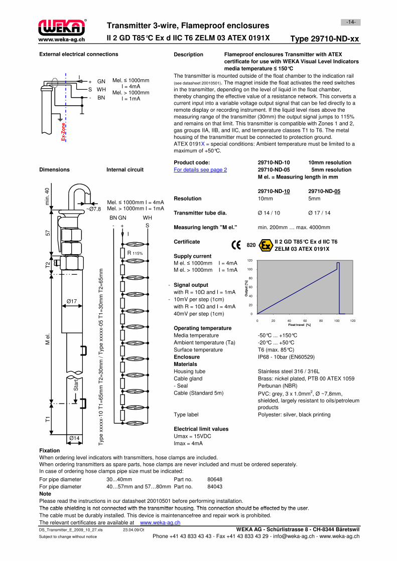
Type 29710-ND-xx
Description
29710-ND-10 10mm resolution
29710-ND-05 5mm resolution
M el. = Measuring length in mm
29710-ND-10 29710-ND-05
10mm 5mm
Transmitter tube dia. Ø 14 / 10 Ø 17 / 14
Measuring length "M el."
Certificate II 2 GD T85°C Ex d IIC T6
ZELM 03 ATEX 0191X
Internal circuit
Supply current
For details see page 2Dimensions
Resolution
Product code:
External electrical connections Flameproof enclosures Transmitter with ATEX
certificate for use with WEKA Visual Level Indicators
media temperature ≤ 150°C
The transmitter is mounted outside of the float chamber to the indication rail
(see datasheet 20010501). The magnet inside the float activates the reed switches
in the transmitter, depending on the level of liquid in the float chamber,
thereby changing the effective value of a resistance network. This converts a
current input into a variable voltage output signal that can be fed directly to a
remote display or recording instrument. If the liquid level rises above the
measuring range of the transmitter (30mm) the output signal jumps to 115%
and remains on that limit. This transmitter is compatible with Zones 1 and 2,
gas groups IIA, IIB, and IIC, and temperature classes T1 to T6. The metal
housing of the transmitter must be connected to protection ground.
ATEX 0191X = special conditions: Ambient temperature must be limited to a
maximum of +50°C.
Transmitter 3-wire, Flameproof enclosures
820
II 2 GD T85°C Ex d IIC T6 ZELM 03 ATEX 0191X
min. 200mm … max. 4000mm
-14-
Mel. ≤ 1000mm I = 4mAMel. > 1000mm I = 1mA
- + S
BN GN WH
I
R 115%
+ Mel. ≤ 1000mmI = 4mA
Mel. > 1000mmI = 1mA
S
-
GN
WH
BN
I
Ex-Z
on
e
min
. 40
~Ø7,8
57
-
with R = 10Ω and I = 1mA
- 10mV per step (1cm)
with R = 10Ω and I = 4mA
40mV per step (1cm)
Media temperature -50°C ... +150°C
Ambient temperature (Ta) -20°C ... +50°C
Surface temperature T6 (max. 85°C)
IP68 - 10bar (EN60529)
Housing tube Stainless steel 316 / 316L
Cable gland Brass: nickel plated, PTB 00 ATEX 1059
- Seal Perbunan (NBR)
Cable (Standard 5m)
Type label Polyester: silver, black printing
Electrical limit values
Umax = 15VDC
Imax = 4mA
Fixation
For pipe diameter 30...40mm Part no. 80648
For pipe diameter 40…57mm and 57…80mm Part no. 84043
Please read the instructions in our datasheet 20010501 before performing installation.
The cable shielding is not connected with the transmitter housing. This connection should be effected by the user.
Note
Signal output
Operating temperature
Materials
Supply current
Type x
xxxx-1
0 T
1=
65m
m T
2=
30m
m /
Type x
xxxx-0
5 T
1=
30m
m T
2=
65m
m
Enclosure
When ordering level indicators with transmitters, hose clamps are included.
When ordering transmitters as spare parts, hose clamps are never included and must be ordered seperately.
In case of ordering hose clamps pipe size must be indicated:
PVC: grey, 3 x 1.0mm2, Ø ~7,8mm,
shielded, largely resistant to oils/petroleum
products
M el. ≤ 1000mm I = 4mA
M el. > 1000mm I = 1mA
0
20
40
60
80
100
120
0 20 40 60 80 100 120
Ou
tpu
t [%
]
Float travel [%]
R 115%
T2
M e
l.T
1
Ø14
Ø17
Sta
rt
The cable shielding is not connected with the transmitter housing. This connection should be effected by the user.
The cable must be durably installed. This device is maintenancefree and repair work is prohibited.
The relevant certificates are available at www.weka-ag.ch
DS_Transmitter_E_2009_10_27.xls 23.04.09/Ot WEKA AG - Schürlistrasse 8 - CH-8344 Bäretswil
Subject to change without notice Phone +41 43 833 43 43 - Fax +41 43 833 43 29 - [email protected] - www.weka-ag.ch
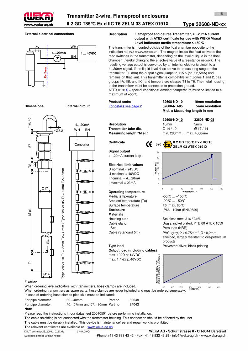
Type 32608-ND-xx
Description
32608-ND-10 10mm resolution
32608-ND-05 5mm resolution
M el. = Measuring length in mm
32608-ND-10 32608-ND-05
10mm 5mm
Transmitter tube dia. Ø 14 / 10 Ø 17 / 14
Measuring length "M el."
Certificate II 2 GD T85°C Ex d IIC T6
ZELM 03 ATEX 0191X
Signal output
4…20mA current loop
Dimensions For details see page 2
min. 200mm … max. 4000mm
Internal circuit
-15-
Resolution
The transmitter is mounted outside of the float chamber opposite to the
indication rail (see datasheet 20010501). The magnet inside the float activates the
reed switches in the transmitter, depending on the level of liquid in the float
chamber, thereby changing the effective value of a resistance network. The
resulting voltage output is converted by an internal electronic circuit to a
4...20mA signal. If the liquid level rises above the measuring range of the
transmitter (30 mm) the output signal jumps to 115% (ca. 22,5mA) and
remains on that limit. This transmitter is compatible with Zones 1 and 2, gas
groups IIA, IIB, and IIC, and temperature classes T1 to T6. The metal housing
of the transmitter must be connected to protection ground.
ATEX 0191X = special conditions: Ambient temperature must be limited to a
maximum of +50°C.
Transmitter 2-wire, Flameproof enclosures
820
Flameproof enclosures Transmitter, 4…20mA current
output with ATEX certificate for use with WEKA Visual
Level Indicators media temperature ≤ 150°C
Product code:
II 2 GD T85°C Ex d IIC T6 ZELM 03 ATEX 0191X
External electrical connections
Converter
BNWH
-+
4…20mA
20
24
4…20mA
WH
BN
+
-
14 … 40VDC
Ex-Z
on
e
min
. 40
~Ø8,2
57
Electrical limit values
U nominal = 24VDC
U maximal = 40VDC
I nominal = 4…20mA
I maximal = 23mA
Media temperature -50°C ... +150°C
Ambient temperature (Ta) -20°C ... +50°C
Surface temperature T6 (max. 85°C)
IP68 - 10bar (EN60529)
Housing tube Stainless steel 316 / 316L
Cable gland Brass: nickel plated, PTB 00 ATEX 1059
- Seal Perbunan (NBR)
Cable (Standard 5m)
Type label Polyester: silver, black printing
Output load (including cables)
max. 100Ω at 14VDC
max. 1.4kΩ at 40VDC
Fixation
For pipe diameter 30...40mm Part no. 80648
For pipe diameter 40…57mm and 57…80mm Part no. 84043
Please read the instructions in our datasheet 20010501 before performing installation.
The cable shielding is not connected with the transmitter housing. This connection should be effected by the user.
Note
Enclosure
When ordering level indicators with transmitters, hose clamps are included.
When ordering transmitters as spare parts, hose clamps are never included and must be ordered seperately.
In case of ordering hose clamps pipe size must be indicated:
PVC: grey, 2 x 0.75mm2, Ø ~8,2mm,
shielded, largely resistant to oils/petroleum
products
Type x
xxxx-1
0 T
1=
65m
m T
2=
30m
m /
Type x
xxxx-0
5 T
1=
30m
m T
2=
65m
m
Materials
Operating temperature
0
4
8
12
16
20
0 20 40 60 80 100 120
Ou
tpu
t [m
A]
Float travel [%]
1416182022242628303234363840
100 300 500 700 900 1100 1300
Sp
eis
un
g /
Su
pp
ly [
VD
C]
load [Ohm]
T2
M e
l.T
1
Ø14
Ø17
Sta
rt
The cable shielding is not connected with the transmitter housing. This connection should be effected by the user.
The cable must be durably installed. This device is maintenancefree and repair work is prohibited.
The relevant certificates are available at www.weka-ag.ch
DS_Transmitter_E_2009_10_27.xls 23.04.09/Ot WEKA AG - Schürlistrasse 8 - CH-8344 Bäretswil
Subject to change without notice Phone +41 43 833 43 43 - Fax +41 43 833 43 29 - [email protected] - www.weka-ag.ch
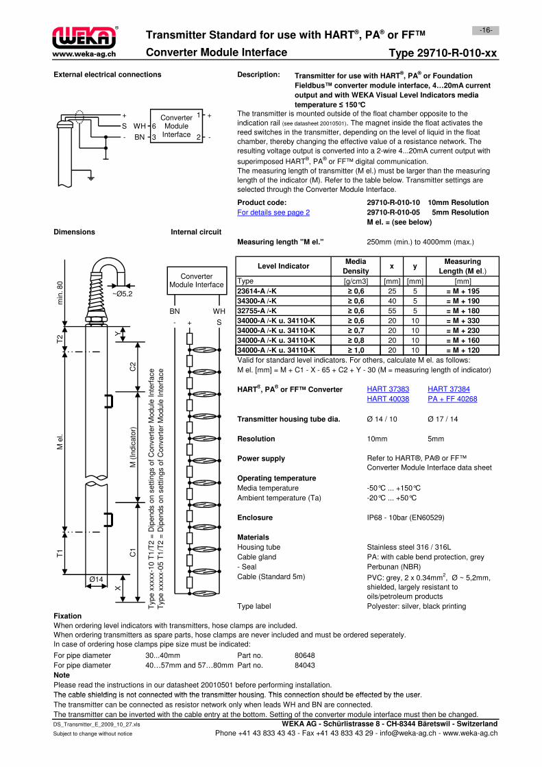
Converter Module Interface Type 29710-R-010-xx
External electrical connections Description:
Product code: 29710-R-010-10 10mm Resolution
29710-R-010-05 5mm Resolution
M el. = (see below)
Measuring length "M el." 250mm (min.) to 4000mm (max.)
[mm] [mm]
25 5
40 5
55 5
20 10
20 10
20 10
20 10
32755-A /-K
= M + 190
= M + 180
Media
Densityy
34000-A /-K u. 34110-K
Dimensions
34300-A /-K
≥ 0,6
[mm]
Level Indicator
= M + 160
≥ 0,6
= M + 195
-16-
For details see page 2
= M + 33034000-A /-K u. 34110-K
= M + 120≥ 1,0
Measuring
Length (M el.)
The transmitter is mounted outside of the float chamber opposite to the
indication rail (see datasheet 20010501). The magnet inside the float activates the
reed switches in the transmitter, depending on the level of liquid in the float
chamber, thereby changing the effective value of a resistance network. The
resulting voltage output is converted into a 2-wire 4...20mA current output with
superimposed HART®, PA
® or FF™ digital communication.
The measuring length of transmitter (M el.) must be larger than the measuring
length of the indicator (M). Refer to the table below. Transmitter settings are
selected through the Converter Module Interface.
Transmitter for use with HART®, PA
® or Foundation
Fieldbus™ converter module interface, 4…20mA current
output and with WEKA Visual Level Indicators media
temperature ≤ 150°C
23614-A /-K
≥ 0,6
≥ 0,6
34000-A /-K u. 34110-K
x
Type
34000-A /-K u. 34110-K
Transmitter Standard for use with HART®, PA® or FF™
Internal circuit
≥ 0,7
≥ 0,8
= M + 230
[g/cm3]
- + S
BN WH
Converter Module Interface
+
S
-
WH
BN
6
3 2
1 +
-
ConverterModule
Interface
T2
min
. 80
~Ø5,2
Y
20 10
Valid for standard level indicators. For others, calculate M el. as follows:
M el. [mm] = M + C1 - X - 65 + C2 + Y - 30 (M = measuring length of indicator)
HART®, PA
® or FF™ Converter
Transmitter housing tube dia. Ø 14 / 10 Ø 17 / 14
10mm 5mm
Power supply
Media temperature -50°C ... +150°C
Ambient temperature (Ta) -20°C ... +50°C
Enclosure IP68 - 10bar (EN60529)
Housing tube Stainless steel 316 / 316L
Cable gland PA: with cable bend protection, grey
- Seal Perbunan (NBR)
Cable (Standard 5m)
Type label Polyester: silver, black printing
Fixation
For pipe diameter 30...40mm Part no. 80648
For pipe diameter 40…57mm and 57…80mm Part no. 84043
Note
Please read the instructions in our datasheet 20010501 before performing installation.
The cable shielding is not connected with the transmitter housing. This connection should be effected by the user.
When ordering level indicators with transmitters, hose clamps are included.
When ordering transmitters as spare parts, hose clamps are never included and must be ordered seperately.
In case of ordering hose clamps pipe size must be indicated:
Refer to HART®, PA® or FF™
Converter Module Interface data sheet
HART 40038
34000-A /-K u. 34110-K
Type x
xxxx-1
0 T
1/T
2 =
Dip
ends o
n s
ett
ings o
f C
onvert
er
Module
Inte
rface
Type x
xxxx-0
5 T
1/T
2 =
Dip
ends o
n s
ett
ings o
f C
onvert
er
Module
Inte
rface
PVC: grey, 2 x 0.34mm2, Ø ~ 5,2mm,
shielded, largely resistant to
oils/petroleum products
HART 37383 HART 37384
Materials
= M + 120
Operating temperature
≥ 1,0
PA + FF 40268
Resolution
M e
l.T
1
Ø14
X
C1
C2
M (
Indic
ato
r)
The cable shielding is not connected with the transmitter housing. This connection should be effected by the user.
The transmitter can be connected as resistor network only when leads WH and BN are connected.
The transmitter can be inverted with the cable entry at the bottom. Setting of the converter module interface must then be changed.
DS_Transmitter_E_2009_10_27.xls WEKA AG - Schürlistrasse 8 - CH-8344 Bäretswil - Switzerland
Subject to change without notice Phone +41 43 833 43 43 - Fax +41 43 833 43 29 - [email protected] - www.weka-ag.ch
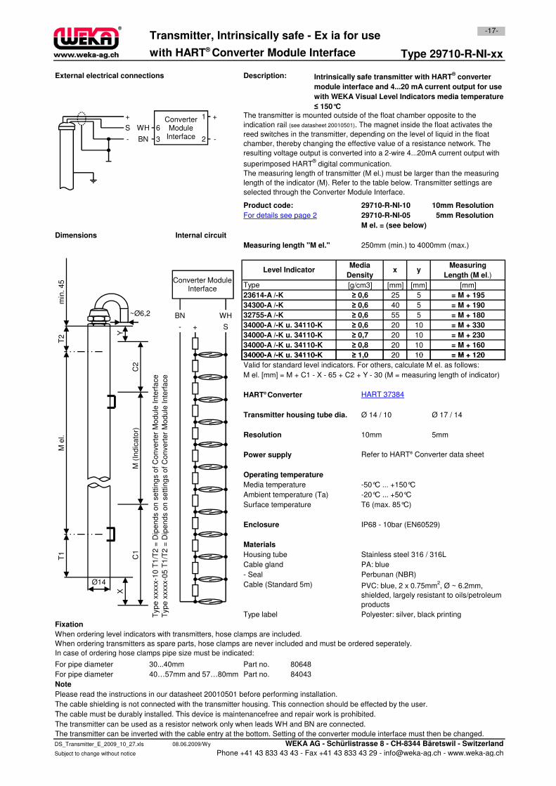
Type 29710-R-NI-xx
External electrical connections Description:
Product code: 29710-R-NI-10 10mm Resolution
29710-R-NI-05 5mm Resolution
M el. = (see below)
Measuring length "M el." 250mm (min.) to 4000mm (max.)
[mm] [mm]
25 5
40 5
55 5
20 10
20 10
20 10
20 10
= M + 230
≥ 0,8
34000-A /-K u. 34110-K
= M + 160
[mm]
34000-A /-K u. 34110-K
≥ 0,7
34000-A /-K u. 34110-K
32755-A /-K
Level Indicator
Type
= M + 195
= M + 190
≥ 0,6
≥ 0,6
≥ 0,6
[g/cm3]
Transmitter, Intrinsically safe - Ex ia for use
with HART® Converter Module Interface
xMedia
Density
≥ 0,6
= M + 120
34000-A /-K u. 34110-K
≥ 1,0
34300-A /-K
23614-A /-K
-17-
y
= M + 180
= M + 330
Measuring
Length (M el.)
Intrinsically safe transmitter with HART® converter
module interface and 4...20 mA current output for use
with WEKA Visual Level Indicators media temperature
≤ 150°CThe transmitter is mounted outside of the float chamber opposite to the
indication rail (see datasheet 20010501). The magnet inside the float activates the
reed switches in the transmitter, depending on the level of liquid in the float
chamber, thereby changing the effective value of a resistance network. The
resulting voltage output is converted into a 2-wire 4...20mA current output with
superimposed HART® digital communication.
The measuring length of transmitter (M el.) must be larger than the measuring
length of the indicator (M). Refer to the table below. Transmitter settings are
selected through the Converter Module Interface.
Internal circuitDimensions
For details see page 2
+
S
-
WH
BN
6
3 2
1 +
-
Converter Module
Interface
- + S
BN WH
Converter Module Interface
T2
min
. 4
5
~Ø6,2
Y
20 10
Valid for standard level indicators. For others, calculate M el. as follows:
M el. [mm] = M + C1 - X - 65 + C2 + Y - 30 (M = measuring length of indicator)
HART® Converter
Transmitter housing tube dia. Ø 14 / 10 Ø 17 / 14
10mm 5mm
Power supply Refer to HART® Converter data sheet
Media temperature -50°C ... +150°C
Ambient temperature (Ta) -20°C ... +50°C
Surface temperature T6 (max. 85°C)
Enclosure IP68 - 10bar (EN60529)
Housing tube Stainless steel 316 / 316L
Cable gland PA: blue
- Seal Perbunan (NBR)
Cable (Standard 5m)
Type label Polyester: silver, black printing
Fixation
For pipe diameter 30...40mm Part no. 80648
For pipe diameter 40…57mm and 57…80mm Part no. 84043
Note
Please read the instructions in our datasheet 20010501 before performing installation.
The cable shielding is not connected with the transmitter housing. This connection should be effected by the user.
The cable must be durably installed. This device is maintenancefree and repair work is prohibited.
34000-A /-K u. 34110-K = M + 120
Typ
e x
xxxx-1
0 T
1/T
2 =
Dip
en
ds o
n s
ettin
gs o
f C
on
ve
rte
r M
od
ule
In
terf
ace
Typ
e x
xxxx-0
5 T
1/T
2 =
Dip
en
ds o
n s
ettin
gs o
f C
on
ve
rte
r M
od
ule
In
terf
ace
≥ 1,0
HART 37384
Resolution
When ordering level indicators with transmitters, hose clamps are included.
When ordering transmitters as spare parts, hose clamps are never included and must be ordered seperately.
In case of ordering hose clamps pipe size must be indicated:
Operating temperature
PVC: blue, 2 x 0.75mm2, Ø ~ 6.2mm,
shielded, largely resistant to oils/petroleum
products
Materials
M e
l.T
1
Ø14
X
C1
C2
M (
Ind
ica
tor)
The cable must be durably installed. This device is maintenancefree and repair work is prohibited.
The transmitter can be used as a resistor network only when leads WH and BN are connected.
The transmitter can be inverted with the cable entry at the bottom. Setting of the converter module interface must then be changed.
DS_Transmitter_E_2009_10_27.xls 08.06.2009/Wy WEKA AG - Schürlistrasse 8 - CH-8344 Bäretswil - Switzerland
Subject to change without notice Phone +41 43 833 43 43 - Fax +41 43 833 43 29 - [email protected] - www.weka-ag.ch
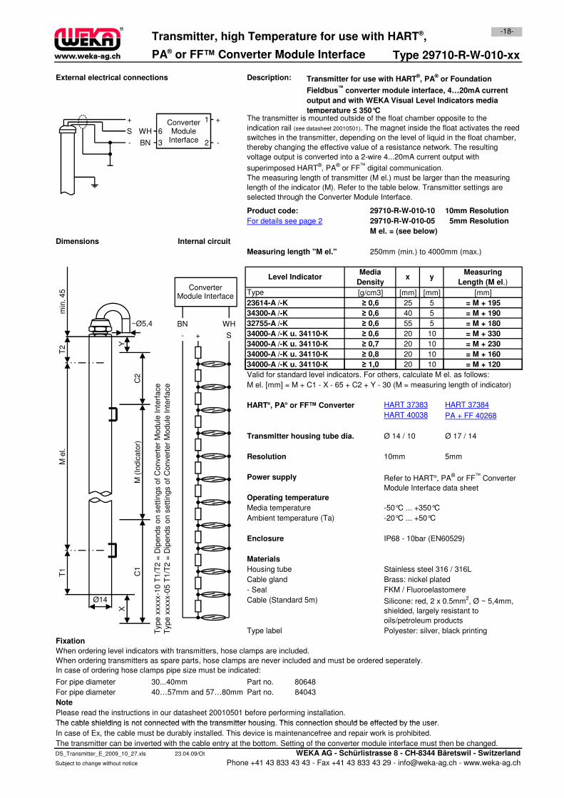
PA® or FF™ Converter Module Interface Type 29710-R-W-010-xx
External electrical connections Description:
Product code: 29710-R-W-010-10 10mm Resolution
29710-R-W-010-05 5mm Resolution
M el. = (see below)
Measuring length "M el." 250mm (min.) to 4000mm (max.)
[mm] [mm]
25 5
40 5
55 5
20 10
20 10
20 10
20 10
23614-A /-K
= M + 330
Internal circuit
≥ 0,6
Level Indicator
Type [mm]
= M + 180
= M + 190
Transmitter for use with HART®, PA
® or Foundation
Fieldbus™
converter module interface, 4…20mA current
output and with WEKA Visual Level Indicators media
temperature ≤ 350°CThe transmitter is mounted outside of the float chamber opposite to the
indication rail (see datasheet 20010501). The magnet inside the float activates the reed
switches in the transmitter, depending on the level of liquid in the float chamber,
thereby changing the effective value of a resistance network. The resulting
voltage output is converted into a 2-wire 4...20mA current output with
superimposed HART®, PA
® or FF
™ digital communication.
The measuring length of transmitter (M el.) must be larger than the measuring
length of the indicator (M). Refer to the table below. Transmitter settings are
selected through the Converter Module Interface.
34300-A /-K
= M + 195
≥ 0,6
Media
Density
34000-A /-K u. 34110-K
34000-A /-K u. 34110-K
= M + 120
= M + 160
yMeasuring
Length (M el.)
Dimensions
≥ 0,7 = M + 230
34000-A /-K u. 34110-K ≥ 1,0
34000-A /-K u. 34110-K ≥ 0,6
≥ 0,8
x
32755-A /-K
≥ 0,6
[g/cm3]
-18-Transmitter, high Temperature for use with HART®,
For details see page 2
+
S
-
WH
BN
6
3 2
1 +
-
ConverterModule
Interface
- + S
BN WH
Converter Module Interface
T2
min
. 45
~Ø5,4
Y
20 10
Valid for standard level indicators. For others, calculate M el. as follows:
M el. [mm] = M + C1 - X - 65 + C2 + Y - 30 (M = measuring length of indicator)
HART®, PA® or FF™ Converter
Transmitter housing tube dia. Ø 14 / 10 Ø 17 / 14
10mm 5mm
Power supply
Media temperature -50°C ... +350°C
Ambient temperature (Ta) -20°C ... +50°C
Enclosure IP68 - 10bar (EN60529)
Materials
Housing tube Stainless steel 316 / 316L
Cable gland Brass: nickel plated
- Seal FKM / Fluoroelastomere
Cable (Standard 5m)
Type label Polyester: silver, black printing
Fixation
For pipe diameter 30...40mm Part no. 80648
For pipe diameter 40…57mm and 57…80mm Part no. 84043
Note
Please read the instructions in our datasheet 20010501 before performing installation.
The cable shielding is not connected with the transmitter housing. This connection should be effected by the user.
Silicone: red, 2 x 0.5mm2, Ø ~ 5,4mm,
shielded, largely resistant to
oils/petroleum products
Operating temperature
HART 37384
Refer to HART®, PA® or FF
™ Converter
Module Interface data sheet
When ordering level indicators with transmitters, hose clamps are included.
When ordering transmitters as spare parts, hose clamps are never included and must be ordered seperately.
In case of ordering hose clamps pipe size must be indicated:
Type x
xxxx-1
0 T
1/T
2 =
Dip
ends o
n s
ett
ings o
f C
onvert
er
Module
Inte
rface
Type x
xxxx-0
5 T
1/T
2 =
Dip
ends o
n s
ett
ings o
f C
onvert
er
Module
Inte
rface
= M + 120
HART 37383
HART 40038 PA + FF 40268
34000-A /-K u. 34110-K ≥ 1,0
Resolution
M e
l.T
1
Ø14
X
C1
C2
M (
Indic
ato
r)
The cable shielding is not connected with the transmitter housing. This connection should be effected by the user.
In case of Ex, the cable must be durably installed. This device is maintenancefree and repair work is prohibited.
The transmitter can be inverted with the cable entry at the bottom. Setting of the converter module interface must then be changed.
DS_Transmitter_E_2009_10_27.xls 23.04.09/Ot WEKA AG - Schürlistrasse 8 - CH-8344 Bäretswil - Switzerland
Subject to change without notice Phone +41 43 833 43 43 - Fax +41 43 833 43 29 - [email protected] - www.weka-ag.ch
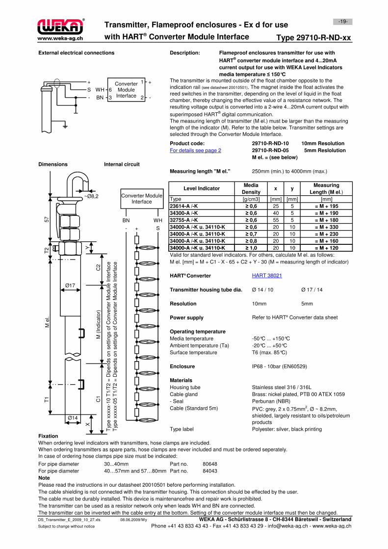
Type 29710-R-ND-xx
External electrical connections Description:
Product code: 29710-R-ND-10 10mm Resolution
29710-R-ND-05 5mm Reslolution
M el. = (see below)
Measuring length "M el." 250mm (min.) to 4000mm (max.)
[mm] [mm]
25 5
40 5
55 5
20 10
20 10
20 10
20 10
34000-A /-K u. 34110-K
34000-A /-K u. 34110-K
32755-A /-K
[mm]
34000-A /-K u. 34110-K
with HART® Converter Module Interface
Dimensions
Level Indicator
Type
≥ 0,6
≥ 0,6
= M + 120
≥ 0,6
34300-A /-K
23614-A /-K
≥ 1,0
34000-A /-K u. 34110-K
≥ 0,7
= M + 180
For details see page 2
≥ 0,8
= M + 230
≥ 0,6
x y
= M + 330
= M + 190
= M + 160
Transmitter, Flameproof enclosures - Ex d for use
The transmitter is mounted outside of the float chamber opposite to the
indication rail (see datasheet 20010501). The magnet inside the float activates the
reed switches in the transmitter, depending on the level of liquid in the float
chamber, thereby changing the effective value of a resistance network. The
resulting voltage output is converted into a 2-wire 4...20mA current output with
superimposed HART® digital communication.
The measuring length of transmitter (M el.) must be larger than the measuring
length of the indicator (M). Refer to the table below. Transmitter settings are
selected through the Converter Module Interface.
= M + 195
Media
Density
Internal circuit
[g/cm3]
Measuring
Length (M el.)
-19-
Flameproof enclosures transmitter for use with
HART® converter module interface and 4...20mA
current output for use with WEKA Level Indicators
media temperature ≤ 150°C
+
S
-
WH
BN
6
3 2
1 +
-
ConverterModule
Interface
- + S
BN WH
Converter Module Interface
2
~Ø8,2
57
Y 20 10
Valid for standard level indicators. For others, calculate M el. as follows:
M el. [mm] = M + C1 - X - 65 + C2 + Y - 30 (M = measuring length of indicator)
HART® Converter
Transmitter housing tube dia. Ø 14 / 10 Ø 17 / 14
10mm 5mm
Power supply Refer to HART® Converter data sheet
Media temperature -50°C ... +150°C
Ambient temperature (Ta) -20°C ... +50°C
Surface temperature T6 (max. 85°C)
Enclosure IP68 - 10bar (EN60529)
Housing tube Stainless steel 316 / 316L
Cable gland Brass: nickel plated, PTB 00 ATEX 1059
- Seal Perbunan (NBR)
Cable (Standard 5m)
Type label Polyester: silver, black printing
Fixation
For pipe diameter 30...40mm Part no. 80648
For pipe diameter 40…57mm and 57…80mm Part no. 84043
Note
Please read the instructions in our datasheet 20010501 before performing installation.
The cable shielding is not connected with the transmitter housing. This connection should be effected by the user.
The cable must be durably installed. This device is maintenancefree and repair work is prohibited.
When ordering level indicators with transmitters, hose clamps are included.
When ordering transmitters as spare parts, hose clamps are never included and must be ordered seperately.
In case of ordering hose clamps pipe size must be indicated:
Materials
Operating temperature
PVC: grey, 2 x 0.75mm2, Ø ~ 8.2mm,
shielded, largely resistant to oils/petroleum
products
34000-A /-K u. 34110-K
Typ
e x
xxxx-1
0 T
1/T
2 =
Dip
en
ds o
n s
ettin
gs o
f C
on
ve
rte
r M
od
ule
In
terf
ace
Typ
e x
xxxx-0
5 T
1/T
2 =
Dip
en
ds o
n s
ettin
gs o
f C
on
ve
rte
r M
od
ule
In
terf
ace
Resolution
HART 38021
= M + 120≥ 1,0
T2
M e
l.T
1
Ø14
Ø17
X
C1
Y
C2
M (
Ind
ica
tor)
The cable must be durably installed. This device is maintenancefree and repair work is prohibited.
The transmitter can be used as a resistor network only when leads WH and BN are connected.
The transmitter can be inverted with the cable entry at the bottom. Setting of the converter module interface must then be changed.
DS_Transmitter_E_2009_10_27.xls 08.06.2009/Wy WEKA AG - Schürlistrasse 8 - CH-8344 Bäretswil - Switzerland
Subject to change without notice Phone +41 43 833 43 43 - Fax +41 43 833 43 29 - [email protected] - www.weka-ag.ch
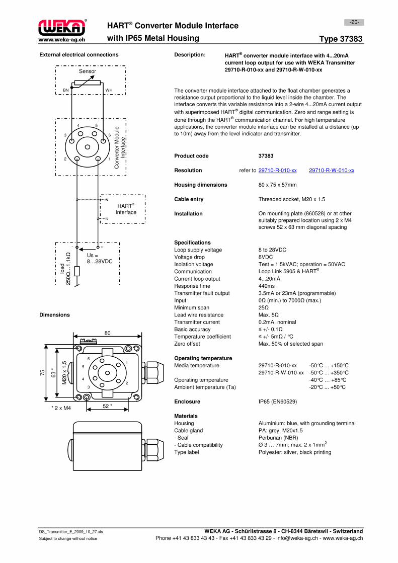
Type 37383
External electrical connections Description:
Product code 37383
Resolution
Housing dimensions 80 x 75 x 57mm
Cable entry Threaded socket, M20 x 1.5
Installation
Specifications
Loop supply voltage 8 to 28VDC
Voltage drop 8VDC
29710-R-010-xx
-20-HART® Converter Module Interface
with IP65 Metal Housing
The converter module interface attached to the float chamber generates a
resistance output proportional to the liquid level inside the chamber. The
interface converts this variable resistance into a 2-wire 4...20mA current output
with superimposed HART® digital communication. Zero and range setting is
done through the HART® communication channel. For high temperature
applications, the converter module interface can be installed at a distance (up
to 10m) away from the level indicator and transmitter.
On mounting plate (860528) or at other
suitably prepared location using 2 x M4
screws 52 x 63 mm diagonal spacing
29710-R-W-010-xx
HART® converter module interface with 4...20mA
current loop output for use with WEKA Transmitter
29710-R-010-xx and 29710-R-W-010-xx
refer to
12
3
4 5
WH
ΩSensor
BN
HART®
Interface
+-
Us =
Convert
er
Module
In
terf
ace
6
Voltage drop 8VDC
Isolation voltage Test = 1.5kVAC; operation = 50VAC
Communication Loop Link 5905 & HART®
Current loop output 4...20mA
Response time 440ms
Transmitter fault output 3.5mA or 23mA (programmable)
Input 0Ω (min.) to 7000Ω (max.)
Minimum span 25Ω
Dimensions Lead wire resistance Max. 5Ω
Transmitter current 0.2mA, nominal
Basic accuracy ≤ +/- 0.1Ω
Temperature coefficient ≤ +/- 5mΩ / °C
Zero offset Max. 50% of selected span
Media temperature 29710-R-010-xx -50°C ... +150°C
29710-R-W-010-xx -50°C ... +350°C
Operating temperature -40°C … +85°C
Ambient temperature (Ta) -20°C ... +50°C
Enclosure IP65 (EN60529)
Materials
Housing Aluminium: blue, with grounding terminal
Cable gland PA: grey, M20x1.5
- Seal Perbunan (NBR)
- Cable compatibility Ø 3 … 7mm; max. 2 x 1mm2
Type label Polyester: silver, black printing
Operating temperature1
23
4
5
6
52 *
M20 x
1,5
80
63 *
75
* 2 x M4
load
250Ω
…1,1
kΩ Us =
8…28VDC
DS_Transmitter_E_2009_10_27.xls WEKA AG - Schürlistrasse 8 - CH-8344 Bäretswil - Switzerland
Subject to change without notice Phone +41 43 833 43 43 - Fax +41 43 833 43 29 - [email protected] - www.weka-ag.ch
0
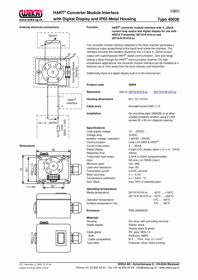
Type 40038
External electrical connections Function
Product code 40038
Resolution
Housing dimensions 80 x 75 x 57mm
Cable entry threaded socket M20 x 1,5
Installation
Specifications
On mounting plate (860528) or at other
suitably prepared location using 2 x M4
screws 52 x 63 mm diagonal spacing
29710-R-W-010-xx
HART® Converter Module Interface-21-
with Digital Display and IP65 Metal Housing
29710-R-010-xx
HART® converter module interface with 4...20mA
current loop output and digital display for use with
WEKA Transmitter 29710-R-010-xx and
29710-R-W-010-xx
The converter module interface attached to the float chamber generates a
resistance output proportional to the liquid level inside the chamber. The
interface converts this variable resistance into a 2-wire 4...20mA current
output with superimposed HART® digital communication. Zero and range
setting is done through the HART® communication channel. For high
temperature applications, the converter module interface can be installed at a
distance (up to 10m) away from the level indicator and transmitter.
Additionally there is a digital display built in to the terminal box
refer to
1
WH
Sensor
BN
-+
Us = 8…28VDC
Load 1,1
kΩ
+-2
3
4 5
Convert
er
Module
Inte
rface
6
1 2
+ -
RD BK
HART®
Interface
Specifications
Loop supply voltage 15 … 35VDC
Voltage drop 14VDC
Isolation voltage / operation 1,5kVAC / 50VAC
Communication Loop Link 5905 & HART®
Dimensions Current loop output 4 … 20mA
Digital display 4 digit LCD, display value in % ≙ 4…20mA
Response time 440ms
Transmitter fault output 3.5mA or 23mA (programmable)
Input 0Ω (min.) to 7000Ω (max.)
Minimum span min. 25Ω
Lead wire resistance max. 5Ω
Transmitter current 0.2mA, nominal
Basic accuracy ≤ +/- 0,1Ω
Temperature coefficient ≤ +/- 5mΩ / °C
Zero offset max. 50% of selected span
Operating termperature
Media temperature 29710-R-010-xx -50°C ... +150°C
29710-R-W-010-xx -50°C ... +350°C
Operation temperature 0°C … +50°C
Ambient temperature (Ta) 0°C … +50°C
Enclosure IP65 (EN60529)
Materials
Housing Alu: blue, with grounding terminal
Digital display Plastic: black
Display black & green
Cable gland PA: grey, M20x1,5
- Seal Perbunan (NBR)
- Cable compatibility Ø 3 … 7mm, max. 2 x 1mm2
Type label Polyester: silver, black printing
1
2
1
23
4
5
6
52 *
M20 x
1,5
80
63 *
75
* 2 x M4
M20 x
1,5
Load
250Ω
…1
DS_Transmitter_E_2009_10_27.xls WEKA AG - Schürlistrasse 8 - CH-8344 Bäretswil
Subject to change without notice Phone +41 43 833 43 43 - Fax +41 43 833 43 29 - [email protected] - www.weka-ag.ch
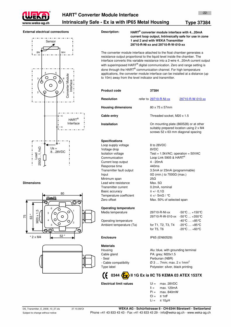
Type 37384
External electrical connections Description:
Product code 37384
Resolution refer to
Housing dimensions 80 x 75 x 57mm
Cable entry Threaded socket, M20 x 1.5
Installation
Specifications
Loop supply voltage 8 to 28VDC
Voltage drop 8VDC
-22-HART® Converter Module Interface
The converter module interface attached to the float chamber generates a
resistance output proportional to the liquid level inside the chamber. The
interface converts this variable resistance into a 2-wire 4...20mA current output
with superimposed HART® digital communication. Zero and range setting is
done through the HART® communication channel. For high temperature
applications, the converter module interface can be installed at a distance (up
to 10m) away from the level indicator and transmitter.
On mounting plate (860528) or at other
suitably prepared location using 2 x M4
screws 52 x 63 mm diagonal spacing
29710-R-NI-xx 29710-R-W-010-xx
HART® converter module interface with 4...20mA
current loop output, Intrinsically safe for use in zone
1 and 2 and with WEKA Transmitter
29710-R-NI-xx and 29710-R-W-010-xx
Intrinsically Safe - Ex ia with IP65 Metal Housing
12
3
4 5
WH
ΩSensor
BN
+-
Us =
Convert
er
Module
In
terf
ace
6
HART®
Interface
Voltage drop 8VDC
Isolation voltage Test = 1.5kVAC; operation = 50VAC
Communication Loop Link 5905 & HART®
Current loop output 4 - 20mA
Response time 440ms
Transmitter fault output 3.5mA or 23mA (programmable)
Input 0Ω (min.) to 7000Ω (max.)
Minimum span 25Ω
Dimensions Lead wire resistance Max. 5Ω
Transmitter current 0.2mA, nominal
Basic accuracy ≤ +/- 0,1Ω
Temperature coefficient ≤ +/- 5mΩ / °C
Zero offset Max. 50% of selected span
Media temperature 29710-R-NI-xx -50°C ... +150°C
29710-R-W-010-xx -50°C ... +350°C
Operating temperature -40°C … +85°C
Ambient temperature (Ta) for T1, T2, T3, T4 -20°C … +85°C
for T5, T6 -20°C … +60°C
Enclosure IP65 (EN60529)
Materials
Housing Alu: blue, with grounding terminal
Cable gland PA: grey; M20x1.5
- Seal Perbunan (NBR)
- Cable compatibility Ø 3 … 7mm; max. 2 x 1mm2
Type label Polyester: silver, black printing
0344 II 1G Ex ia IIC T6 KEMA 03 ATEX 1537X
Electrical limit values Ui = max. 28VDC
Ii =
Pi =
Ci =
max. 120mA
max. 840mW
≤ 1nF
Operating temperature1
23
4
5
6
52 *
M20 x
1,5
80
63 *
75
* 2 x M4
Load
250Ω
…1,1
kΩ Us =
8…28VDC
Ci =
Li =
DS_Transmitter_E_2009_10_27.xls 27.10.09/Ot WEKA AG - Schürlistrasse 8 - CH-8344 Bäretswil - Switzerland
Subject to change without notice Phone +41 43 833 43 43 - Fax +41 43 833 43 29 - [email protected] - www.weka-ag.ch
≤ 10µH
≤ 1nF
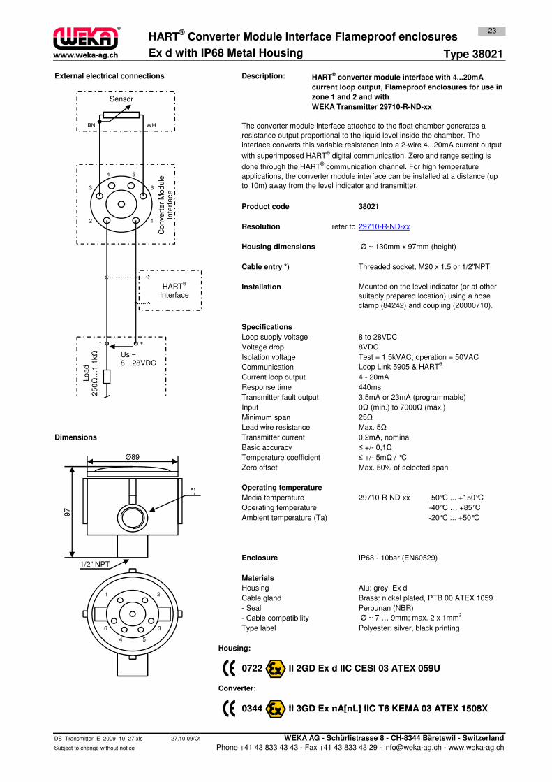
Type 38021
External electrical connections Description:
Product code 38021
Resolution refer to
Housing dimensions Ø ~ 130mm x 97mm (height)
Cable entry *) Threaded socket, M20 x 1.5 or 1/2"NPT
Installation
Specifications
Loop supply voltage 8 to 28VDC
Voltage drop 8VDC
Isolation voltage Test = 1.5kVAC; operation = 50VAC
Ex d with IP68 Metal Housing
HART® Converter Module Interface Flameproof enclosures
The converter module interface attached to the float chamber generates a
resistance output proportional to the liquid level inside the chamber. The
interface converts this variable resistance into a 2-wire 4...20mA current output
with superimposed HART® digital communication. Zero and range setting is
done through the HART® communication channel. For high temperature
applications, the converter module interface can be installed at a distance (up
to 10m) away from the level indicator and transmitter.
HART® converter module interface with 4...20mA
current loop output, Flameproof enclosures for use in
zone 1 and 2 and with
WEKA Transmitter 29710-R-ND-xx
-23-
Mounted on the level indicator (or at other
suitably prepared location) using a hose
clamp (84242) and coupling (20000710).
29710-R-ND-xx12
3
4 5
WH
ΩSensor
BN
+-
Us =
Convert
er
Module
In
terf
ace
6
HART®
Interface
Isolation voltage Test = 1.5kVAC; operation = 50VAC
Communication Loop Link 5905 & HART®
Current loop output 4 - 20mA
Response time 440ms
Transmitter fault output 3.5mA or 23mA (programmable)
Input 0Ω (min.) to 7000Ω (max.)
Minimum span 25Ω
Lead wire resistance Max. 5Ω
Dimensions Transmitter current 0.2mA, nominal
Basic accuracy ≤ +/- 0,1Ω
Temperature coefficient ≤ +/- 5mΩ / °C
Zero offset Max. 50% of selected span
Media temperature 29710-R-ND-xx -50°C ... +150°C
Operating temperature -40°C … +85°C
Ambient temperature (Ta) -20°C ... +50°C
Enclosure IP68 - 10bar (EN60529)
Materials
Housing Alu: grey, Ex d
Cable gland Brass: nickel plated, PTB 00 ATEX 1059
- Seal Perbunan (NBR)
- Cable compatibility Ø ~ 7 … 9mm; max. 2 x 1mm2
Type label Polyester: silver, black printing
Housing:
0722 II 2GD Ex d IIC CESI 03 ATEX 059U
Converter:
0344 II 3GD Ex nA[nL] IIC T6 KEMA 03 ATEX 1508X
Operating temperature
Load
250Ω
…1,1
kΩ Us =
8…28VDC
1 2
3
4 5
6
97
Ø89
1/2" NPT
*)
0344 II 3GD Ex nA[nL] IIC T6 KEMA 03 ATEX 1508X
DS_Transmitter_E_2009_10_27.xls 27.10.09/Ot WEKA AG - Schürlistrasse 8 - CH-8344 Bäretswil - Switzerland
Subject to change without notice Phone +41 43 833 43 43 - Fax +41 43 833 43 29 - [email protected] - www.weka-ag.ch
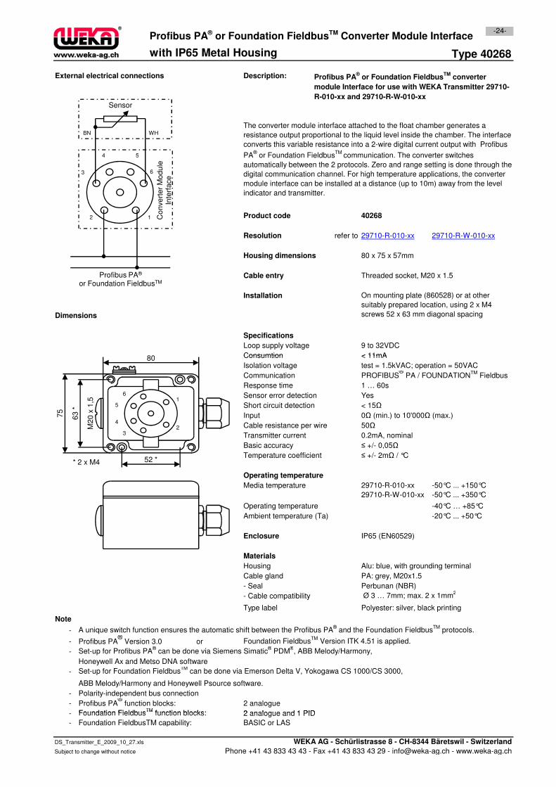
Type 40268
External electrical connections Description:
Product code 40268
Resolution refer to
Housing dimensions 80 x 75 x 57mm
Cable entry Threaded socket, M20 x 1.5
Installation
Dimensions
Specifications
Loop supply voltage 9 to 32VDC
Consumtion < 11mA
-24-
with IP65 Metal Housing
The converter module interface attached to the float chamber generates a
resistance output proportional to the liquid level inside the chamber. The interface
converts this variable resistance into a 2-wire digital current output with Profibus
PA® or Foundation Fieldbus
TM communication. The converter switches
automatically between the 2 protocols. Zero and range setting is done through the
digital communication channel. For high temperature applications, the converter
module interface can be installed at a distance (up to 10m) away from the level
indicator and transmitter.
On mounting plate (860528) or at other
suitably prepared location, using 2 x M4
screws 52 x 63 mm diagonal spacing
Profibus PA® or Foundation FieldbusTM Converter Module Interface
29710-R-010-xx 29710-R-W-010-xx
Profibus PA® or Foundation Fieldbus
TM converter
module Interface for use with WEKA Transmitter 29710-
R-010-xx and 29710-R-W-010-xx
12
3
4 5
WH
Sensor
BN
Co
nve
rte
r M
od
ule
In
terf
ace
6
Profibus PA®
or Foundation FieldbusTM
80 Consumtion < 11mA
Isolation voltage test = 1.5kVAC; operation = 50VAC
Communication PROFIBUS®
PA / FOUNDATIONTM
Fieldbus
Response time 1 … 60s
Sensor error detection Yes
Short circuit detection < 15Ω
Input 0Ω (min.) to 10'000Ω (max.)
Cable resistance per wire 50Ω
Transmitter current 0.2mA, nominal
Basic accuracy ≤ +/- 0,05Ω
Temperature coefficient ≤ +/- 2mΩ / °C
Media temperature 29710-R-010-xx -50°C ... +150°C
29710-R-W-010-xx -50°C ... +350°C
Operating temperature -40°C … +85°C
Ambient temperature (Ta) -20°C ... +50°C
Enclosure IP65 (EN60529)
Materials
Housing Alu: blue, with grounding terminal
Cable gland PA: grey, M20x1.5
- Seal Perbunan (NBR)
- Cable compatibility Ø 3 … 7mm; max. 2 x 1mm2
Type label Polyester: silver, black printing
Note
- A unique switch function ensures the automatic shift between the Profibus PA® and the Foundation Fieldbus
TM protocols.
- Profibus PA®
Version 3.0 or Foundation FieldbusTM
Version ITK 4.51 is applied.
- Set-up for Profibus PA® can be done via Siemens Simatic
® PDM
®, ABB Melody/Harmony,
Honeywell Ax and Metso DNA software
- Set-up for Foundation FieldbusTM
can be done via Emerson Delta V, Yokogawa CS 1000/CS 3000,
ABB Melody/Harmony and Honeywell Psource software.
- Polarity-independent bus connection
- Profibus PA®
function blocks: 2 analogue
- Foundation FieldbusTM
function blocks: 2 analogue and 1 PID
Operating temperature
1
23
4
5
6
52 *
M2
0 x
1,5
80
63
*
75
* 2 x M4
- Foundation FieldbusTM
function blocks: 2 analogue and 1 PID
- Foundation FieldbusTM capability: BASIC or LAS
DS_Transmitter_E_2009_10_27.xls WEKA AG - Schürlistrasse 8 - CH-8344 Bäretswil - Switzerland
Subject to change without notice Phone +41 43 833 43 43 - Fax +41 43 833 43 29 - [email protected] - www.weka-ag.ch
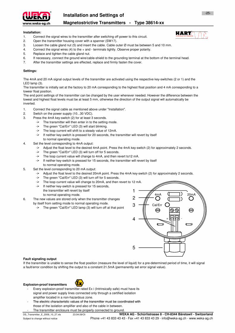
Magnetostrictive Transmitters - Type 38614-xx
Installation:
1. Connect the signal wires to the transmitter after switching off power to this circuit.
2. Open the transmitter housing cover with a spanner (SW17).
3. Loosen the cable gland nut (5) and insert the cable. Cable outer Ø must be between 5 and 10 mm.
4. Connect the signal wires (4) to the + and - terminals tightly. Observe proper polarity.
5. Replace and tighten the cable gland nut.
6. If necessary, connect the ground wire/cable-shield to the grounding terminal at the bottom of the terminal head.
7. After the transmitter settings are effected, replace and firmly fasten the cover.
Settings:
1. Connect the signal cable as mentioned above under "Installation".
2. Switch on the power supply (10...30 VDC).
3. Press the 4mA key-switch (2) for at least 3 seconds.
- The transmitter will then enter in to the setting mode.
- The green "Cal/Err" LED (3) will start blinking.
- The loop current will shift to a steady value of 12mA.
- If neither key-switch is pressed for 20 seconds, the transmitter will revert by itself
to normal operating mode.
4. Set the level corresponding to 4mA output:
- Adjust the float level to the desired 4mA point. Press the 4mA key-switch (2) for approximately 2 seconds.
- The green "Cal/Err" LED (3) will turn off for 5 seconds.
Installation and Settings of-25-
The 4mA and 20 mA signal output levels of the transmitter are activated using the respective key-switches (2 or 1) and the
LED lamp (3).
The transmitter is initially set at the factory to 20 mA corresponding to the highest float position and 4 mA corresponding to a
lowesr float position.
The end point settings of the transmitter can be changed by the user whenever needed. However the difference between the
lowest and highest float levels must be at least 5 mm, otherwise the direction of the output signal will automatically be
inverted.
- The green "Cal/Err" LED (3) will turn off for 5 seconds.
- The loop current value will change to 4mA, and then revert to12 mA.
- If neither key-switch is pressed for 15 seconds, the transmitter will revert by itself
to normal operating mode.
5. Set the level corresponding to 20 mA output:
- Adjust the float level to the desired 20mA point. Press the 4mA key-switch (2) for approximately 2 seconds.
- The green "Cal/Err" LED (3) will turn off for 5 seconds.
- The loop current value will change to 20mA, and then revert to 12 mA.
- If neither key-switch is pressed for 15 seconds,
the transmitter will revert by itself
to normal operating mode.
6. The new values are stored only when the transmitter changes
by itself from setting mode to normal operating mode.
- The green "Cal/Err" LED lamp (3) will turn off at that point
Fault signaling output
Explosion-proof transmitters
- Every explosion-proof transmitter rated Ex i (Intrinsically safe) must have its
signal and power supply lines connected only through a certified isolation
amplifier located in a non-hazardous zone.
- The electric characteristic values of the transmitter must be coordinated with
If the transmitter is unable to sense the float position (measure the level of liquid) for a pre-determined period of time, it will signal
a fault/error condition by shifting the output to a constant 21.5mA (permanently set error signal value).
+ -
20mA4mA
Cal/Err
4
1
2
3
5
- The electric characteristic values of the transmitter must be coordinated with
those of the isolation amplifier and also of the cable in between.
- The transmitter enclosure must be properly connected to ground.
DS_Transmitter_E_2009_10_27.xls 23.04.09/Ot WEKA AG - Schürlistrasse 8 - CH-8344 Bäretswil - Switzerland
Subject to change without notice Phone +41 43 833 43 43 - Fax +41 43 833 43 29 - [email protected] - www.weka-ag.ch
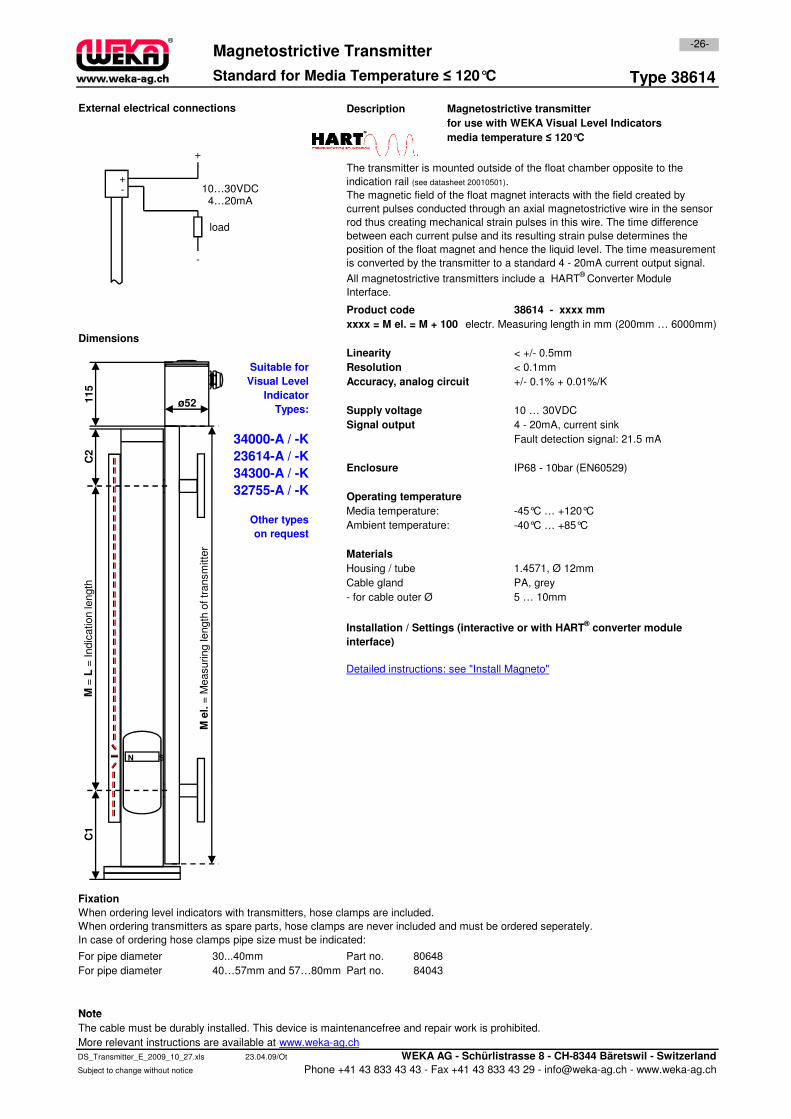
Type 38614
Description Magnetostrictive transmitter
for use with WEKA Visual Level Indicators
media temperature ≤ 120°C
38614 - xxxx mm
xxxx = M el. = M + 100 electr. Measuring length in mm (200mm … 6000mm)
Linearity < +/- 0.5mm
Resolution < 0.1mm
Accuracy, analog circuit +/- 0.1% + 0.01%/K
Supply voltage 10 … 30VDC
Signal output 4 - 20mA, current sink
Fault detection signal: 21.5 mA
Enclosure IP68 - 10bar (EN60529)
Operating temperature
Media temperature: -45°C … +120°C
Dimensions
Suitable for
Visual Level
Indicator
Types:
34000-A / -K
23614-A / -K
34300-A / -K
32755-A / -K
-26-
Product code
Magnetostrictive Transmitter
Standard for Media Temperature ≤ 120°C
External electrical connections
The transmitter is mounted outside of the float chamber opposite to the
indication rail (see datasheet 20010501).
The magnetic field of the float magnet interacts with the field created by
current pulses conducted through an axial magnetostrictive wire in the sensor
rod thus creating mechanical strain pulses in this wire. The time difference
between each current pulse and its resulting strain pulse determines the
position of the float magnet and hence the liquid level. The time measurement
is converted by the transmitter to a standard 4 - 20mA current output signal.
All magnetostrictive transmitters include a HART®
Converter Module
Interface.
10…30VDC4…20mA
+-
-
+
load
C2
115
ø52
Media temperature: -45°C … +120°C
Ambient temperature: -40°C … +85°C
Materials
Housing / tube 1.4571, Ø 12mm
Cable gland PA, grey
- for cable outer Ø 5 … 10mm
Fixation
For pipe diameter 30...40mm Part no. 80648
For pipe diameter 40…57mm and 57…80mm Part no. 84043
Note
Other types
on request
Installation / Settings (interactive or with HART® converter module
interface)
When ordering level indicators with transmitters, hose clamps are included.
When ordering transmitters as spare parts, hose clamps are never included and must be ordered seperately.
In case of ordering hose clamps pipe size must be indicated:
Detailed instructions: see "Install Magneto"
M e
l.=
Measuring length
of tr
ansm
itte
r
M =
L=
Indic
ation le
ngth
N S
C1
Note
The cable must be durably installed. This device is maintenancefree and repair work is prohibited.
More relevant instructions are available at www.weka-ag.ch
DS_Transmitter_E_2009_10_27.xls 23.04.09/Ot WEKA AG - Schürlistrasse 8 - CH-8344 Bäretswil - Switzerland
Subject to change without notice Phone +41 43 833 43 43 - Fax +41 43 833 43 29 - [email protected] - www.weka-ag.ch
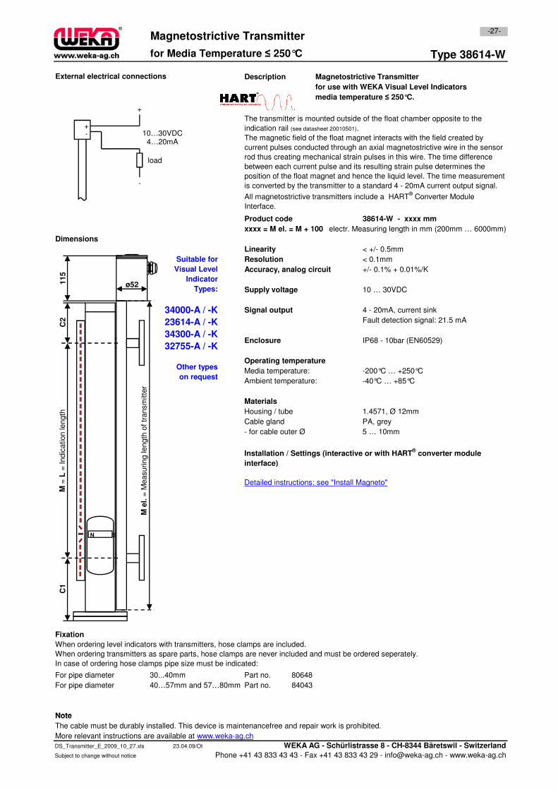
Type 38614-W
Description Magnetostrictive Transmitter
for use with WEKA Visual Level Indicators
media temperature ≤ 250°C.
38614-W - xxxx mm
xxxx = M el. = M + 100 electr. Measuring length in mm (200mm … 6000mm)
Linearity < +/- 0.5mm
Resolution < 0.1mm
Accuracy, analog circuit +/- 0.1% + 0.01%/K
Supply voltage 10 … 30VDC
Signal output 4 - 20mA, current sink
Fault detection signal: 21.5 mA
Enclosure IP68 - 10bar (EN60529)
Operating temperature
Dimensions
External electrical connections
-27-
Product code
Magnetostrictive Transmitter
for Media Temperature ≤ 250°C
Suitable for
Visual Level
Indicator
Types:
34000-A / -K
23614-A / -K
34300-A / -K
32755-A / -K
The transmitter is mounted outside of the float chamber opposite to the
indication rail (see datasheet 20010501).
The magnetic field of the float magnet interacts with the field created by
current pulses conducted through an axial magnetostrictive wire in the sensor
rod thus creating mechanical strain pulses in this wire. The time difference
between each current pulse and its resulting strain pulse determines the
position of the float magnet and hence the liquid level. The time measurement
is converted by the transmitter to a standard 4 - 20mA current output signal.
All magnetostrictive transmitters include a HART® Converter Module
Interface.
10…30VDC4…20mA
+-
-
+
load
C2
115
ø52
Operating temperature
Media temperature: -200°C … +250°C
Ambient temperature: -40°C … +85°C
Materials
Housing / tube 1.4571, Ø 12mm
Cable gland PA, grey
- for cable outer Ø 5 … 10mm
Fixation
For pipe diameter 30...40mm Part no. 80648
For pipe diameter 40…57mm and 57…80mm Part no. 84043
Note
When ordering level indicators with transmitters, hose clamps are included.
When ordering transmitters as spare parts, hose clamps are never included and must be ordered seperately.
In case of ordering hose clamps pipe size must be indicated:
Installation / Settings (interactive or with HART® converter module
interface)
Detailed instructions: see "Install Magneto"
Other types
on request
M e
l.=
Measuring length
of tr
ansm
itte
r
M =
L=
Indic
ation le
ngth
N S
C1
Note
The cable must be durably installed. This device is maintenancefree and repair work is prohibited.
More relevant instructions are available at www.weka-ag.ch
DS_Transmitter_E_2009_10_27.xls 23.04.09/Ot WEKA AG - Schürlistrasse 8 - CH-8344 Bäretswil - Switzerland
Subject to change without notice Phone +41 43 833 43 43 - Fax +41 43 833 43 29 - [email protected] - www.weka-ag.ch
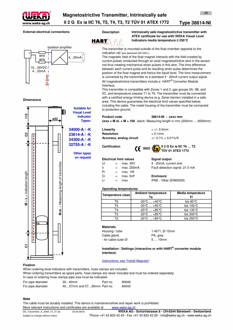
Type 38614-NI
Description
38614-NI - xxxx mm
xxxx = M el. = M + 100 electr. Measuring length in mm (200mm … 6000mm)
Linearity < +/- 0.5mm
Resolution < 0.1mm
Accuracy, analog circuit +/- 0.1% + 0.01%/K
Certification II 2 G Ex ia IIC T6 … T2
TÜV 01 ATEX 1772
Suitable for
Visual Level
Indicator
Types:
34000-A / -K
23614-A / -K
34300-A / -K
32755-A / -K
Dimensions
Magnetostrictive Transmitter, Intrinsically safe
Intrinsically safe magnetostrictive transmitter with
ATEX certificate for use with WEKA Visual Level
Indicators media temperature ≤ 250°C
0032
External electrical connections
-28-
Product code
II 2 G Ex ia IIC T6, T5, T4, T3, T2 TÜV 01 ATEX 1772
The transmitter is mounted outside of the float chamber opposite to the
indication rail (see datasheet 20010501).
The magnetic field of the float magnet interacts with the field created by
current pulses conducted through an axial magnetostrictive wire in the sensor
rod thus creating mechanical strain pulses in this wire. The time difference
between each current pulse and its resulting strain pulse determines the
position of the float magnet and hence the liquid level. The time measurement
is converted by the transmitter to a standard 4 - 20mA current output signal.
All magnetostrictive transmitters include a HART® Converter Module
Interface.
This transmitter is compatible with Zones 1 and 2, gas groups IIA, IIB, and
IIC, and temperature classes T1 to T6. The transmitter must be connected
with a certified energy limiting device (e.g. Zener barrier) installed in a safe
area. This device guarantees the electrical limit values specified below,
including the cable. The metal housing of the transmitter must be connected
to protection ground.
wire
10…30VDC4…20mA
4…20mA
isolation amplifier
+-
wire
Ex-Z
on
e
C2
115
ø52
TÜV 01 ATEX 1772
Ui = 4 - 20mA, current sink
Ii = Fault detection signal: 21.5 mA
Pi =
Ci =
Li = IP68 - 10bar (EN60529)
Materials
Housing / tube 1.4571, Ø 12mm
Cable gland PA, grey
- for cable outer Ø 5 … 10mm
Fixation
For pipe diameter 30...40mm Part no. 80648
For pipe diameter 40…57mm and 57…80mm Part no. 84043
Note
-20°C … +85°C
When ordering level indicators with transmitters, hose clamps are included.
When ordering transmitters as spare parts, hose clamps are never included and must be ordered seperately.
In case of ordering hose clamps pipe size must be indicated:
T2
-20°C … +40°C
bis 250°C
T3
Instructions: see "Install Magneto"
Installation / Settings (interactive or with HART® converter module
interface)
bis 100°C
bis 135°C
bis 200°C
Media temperature
Tf
bis 85°C
Ambient temperature
Ta
max. 1W
-20°C … +85°C
Operating temperatures
max. 5nF
Other types
on requestElectrical limit values
-20°C … +85°C
max. 30V
max. 200mA
T4
-20°C … +55°C
Temperature class
0032
Enclosure
max.
Signal output
T5
T6
M e
l.=
Measuring length
of tr
ansm
itte
r
M =
L=
Indic
ation le
ngth
N S
C1
Note
The cable must be durably installed. This device is maintenancefree and repair work is prohibited.
More relevant instructions and certificates are available at www.weka-ag.ch
DS_Transmitter_E_2009_10_27.xls 23.04.09/Ot WEKA AG - Schürlistrasse 8 - CH-8344 Bäretswil - Switzerland
Subject to change without notice Phone +41 43 833 43 43 - Fax +41 43 833 43 29 - [email protected] - www.weka-ag.ch
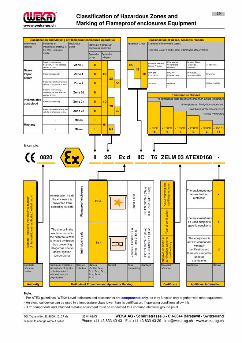
Example:
-29-Classification of Hazardous Zones and
Marking of Flameproof enclosures Equipment
Temperature Classes
2G Ex d IIC
M1
M2
The temperature class specifies the maximum surface temperature
of the apparatus. The ignition temperature
-
< 450°C
T1
< 85°C
T6
< 100°C
T5
< 135°C
T4
< 200°C
T3
< 300°C
T2
surface temperature
must be higher than the maximum
Ethylene,
Ethylene oxide
Ethyl glycol,
Hydrogen sulfide Ethyl ether
Hydrogen Acetylene Carbon disulfide
Town gas,
Acrylonitrile
II ZELM 03 ATEX0168T6
1G
2G
3G
1D
2D
3D
II
II
I
I
II
II
II
II
Methane
Zone 0
Zone 1
Zone 2
Zone 20
Zone 21
Zone 22
Mines
Mines
Classification and Marking of Flameproof enclosures Apparatus Classification of Gases, Aerosols, Vapors
Inflammable
MaterialMarking of Flameproof
enclosures equipment
Apparatus
group
Apparatus
category
Hazardous
zones
Incidence of
inflammable material in
Ex zone. Explosive
media
Apparatus Group Examples of inflammable Gases
[Note:This is only a partial list of inflammable gases/vapors]
Ethyl alcohol,
Cyclohexane,
N-butane
Benzene, Diesel,
Furnace oil,
N-hexane
Acetaldehyde
0820
IIA
IIB
IIC
Present continuously,
frequently, or over extended
periods of time
Present occasionally
Presence unlikely or rare and
only for brief periods of time
Ammonia, Methane,
Ethane, Propane
Present continuously,
frequently, or over extended
periods of time
Present occasionally
Presence unlikely or rare, and
only for brief periods of time
-
-
Gases
Vapor
Steam
Inflamm-able
dust cloud
Note:
- Per ATEX guidelines, WEKA Level Indicators and accessories are components only, as they function only together with other equipment.
- An electrical device can be used in a temperature class lower than its certification, if operating conditions allow this.
- "Ex" components and attached metallic equipment must be connected to a common electrical ground point.
Intr
ins
ica
lly
sa
fe
Marking
[Omitted here:
Ex o, Ex p, Ex q,
Ex e, Ex m,
Ex n]
Symbol
Zo
ne
s 0
, 1
an
d 2
: E
x ia
Zo
ne
s 1
an
d 2
: E
x ib
U
X
The equipment may
be used subject to
specific conditions
The equipment is
an "Ex" component
with part-
certification and
therefore cannot be
used as
standalone.
Traceability
reference
StandardCertificate
reference
number
Ma
rkin
g -
in
clu
din
g t
he
re
fere
nce
nu
mb
er
of
th
e c
ert
ific
atio
n a
uth
ori
ty (
no
tifie
d b
od
y)
Principle of protection
[All methods of ignition
protection are not
indicated here, for
simplification]
Zone
compatibility
The energy in the
electrical circuit in
the hazardous zone
is limited by design,
thus preventing
dangerous sparks
and/or ignition
temperatures
Fla
me
pro
of
en
clo
su
res
Ex i
An explosion inside
the enclosure is
prevented from
spreading outside
Means of
protection
Authority Methods of Protection and Apparatus Marking Certificate Additional information
-
The equipment may
be used without
restriction
IEC
EN
60
07
9-1
1 (
Ga
s)
IEC
EN
61
24
1-1
1 (
Du
st)
IEC
EN
60
07
9-1
(G
as)
IEC
EN
61
24
1-1
(D
ust)
Conditions Marking
2G Ex d IIC -IIA
bb
revia
ted
na
me
of
ce
rtific
atio
n a
uth
ori
ty
(no
tifie
d b
od
y)
Zo
ne
1 o
r 2
Ex d
ZELM 03 ATEX0168A
TE
X m
ark
ing
an
d
ce
rtific
ate
nu
mb
er
Ye
ar
of
ce
rtific
atio
n
T60820
DS_Transmitter_E_2009_10_27.xls 23.04.09/Ot WEKA AG - Schürlistrasse 8 - CH-8344 Bäretswil - Switzerland
Subject to change without notice Phone +41 43 833 43 43 - Fax +41 43 833 43 29 - [email protected] - www.weka-ag.ch
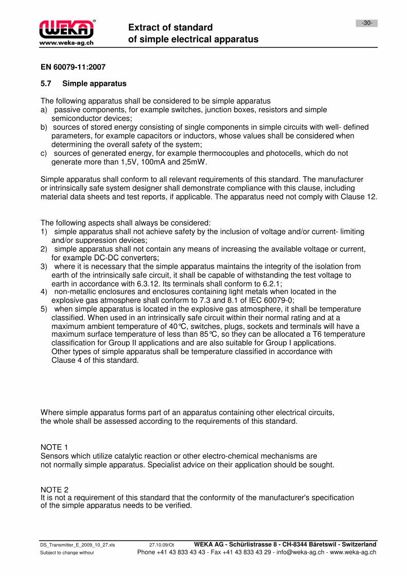
EN 60079-11:2007
5.7 Simple apparatus
The following apparatus shall be considered to be simple apparatusa) passive components, for example switches, junction boxes, resistors and simple
semiconductor devices;b) sources of stored energy consisting of single components in simple circuits with well- defined
parameters, for example capacitors or inductors, whose values shall be considered whendetermining the overall safety of the system;
c) sources of generated energy, for example thermocouples and photocells, which do notgenerate more than 1,5V, 100mA and 25mW.
Simple apparatus shall conform to all relevant requirements of this standard. The manufactureror intrinsically safe system designer shall demonstrate compliance with this clause, includingmaterial data sheets and test reports, if applicable. The apparatus need not comply with Clause 12.
The following aspects shall always be considered:1) simple apparatus shall not achieve safety by the inclusion of voltage and/or current- limiting
and/or suppression devices;2) simple apparatus shall not contain any means of increasing the available voltage or current,
for example DC-DC converters;
Extract of standard
of simple electrical apparatus
-30-
for example DC-DC converters;3) where it is necessary that the simple apparatus maintains the integrity of the isolation from
earth of the intrinsically safe circuit, it shall be capable of withstanding the test voltage toearth in accordance with 6.3.12. Its terminals shall conform to 6.2.1;
4) non-metallic enclosures and enclosures containing light metals when located in theexplosive gas atmosphere shall conform to 7.3 and 8.1 of IEC 60079-0;
5) when simple apparatus is located in the explosive gas atmosphere, it shall be temperatureclassified. When used in an intrinsically safe circuit within their normal rating and at amaximum ambient temperature of 40°C, switches, plugs, sockets and terminals will have amaximum surface temperature of less than 85°C, so they can be allocated a T6 temperatureclassification for Group II applications and are also suitable for Group I applications.Other types of simple apparatus shall be temperature classified in accordance withClause 4 of this standard.
Where simple apparatus forms part of an apparatus containing other electrical circuits,the whole shall be assessed according to the requirements of this standard.
NOTE 1Sensors which utilize catalytic reaction or other electro-chemical mechanisms arenot normally simple apparatus. Specialist advice on their application should be sought.
NOTE 2It is not a requirement of this standard that the conformity of the manufacturer's specificationof the simple apparatus needs to be verified.
DS_Transmitter_E_2009_10_27.xls 27.10.09/Ot WEKA AG - Schürlistrasse 8 - CH-8344 Bäretswil - Switzerland
Phone +41 43 833 43 43 - Fax +41 43 833 43 29 - [email protected] - www.weka-ag.chSubject to change without notice