Embed Size (px)
Citation preview

CI-2001AS/BSWeighing Indicator
OWNER’S MANUAL
CONTENTSPRECAUTIONS 4INTRODUCTION 6 THE FEATURES OF CI-2001AS/CI-2001BS 6TECHNICAL SPECIFICATION 7DIMENSIONS 8FRONT PANEL(CI-2001AS) 9FRONT PANEL(CI-2001BS) 11CONNECTING THE CABLE 13TEST MODE 14 CALIBRATION MODE 17SET MODE 20SERIAL INTERFACE 24ERROR MESSAGE & TROUBLE SHOOTING 28

4
PRECAUTIONS
Place the indicator on a flat and stable surface.
Do not use inflammable materials incleaning.
Do not severely press because the lightpressing of keys can incite the operation.
Keep the main body from rain andkeep in dry area.

5
Do not subject the scale to sudden temperature changes.
Keep the scale away from strong EMI noises may cause incorrect weight readings.

6
INTRODUCTION
THE FEATURES OF CI-2001AS/CI-2001BS
We greatly appreciate your purchase of the CAS industrial indicator. Thesegoods have hold excellent performance and splendid properties through striketests as well as devoting ourselves under severe quality management.CAS indicator(CI-series) is shaped firmly and delicately designed a coincidewith the special requirements of several industrial fields and includes manyfunctions and various external interfaces. Also, it is programmed on the basic ofthe user’s convenience and contains help display functions to be used easily.Before using CI-2001AS/BS, It is recommended to read this manual carefullyand to apply the function application fully.
1. FeaturesAppropriate for weight and measurement systemEasy operation and various functionsSimple full digital calibration(SPACTM:Single pass automatic span calibration)Watchdog circuitry(System restoration)Wall mount type(CI-2001AS/BS)-Standard
2. Main FunctionVarious specification of weight conversion speed(Digital filter function)Various printer connection(RS232 Serial printer)Users can set the desirous max. weight and a division freelySelf hardware testPrompt A/S is available for test of each part of circuit by module is possible

7
TECHNICAL SPECIFICATION
DC 5V, up to 4 350 load cells
20mV, including dead load
0.05mV 5mV
2 V/D(H-44, OIML)0.5 V/D(Non H-44, OIML)
Within 0.01% of FS
Approximately 200,000 counts
5,000dd(H-44, OIML)30,000dd(Non H-44, OIML)
10 times/sec
Load cell excitation voltage
Full scale input signal
Zero adjust range
Input sensitivity
System linearity
A/D internal resolution
A/D external resolution
A/D conversion speed
Analog Part
Full Digital Calibration: SPACTM
(Single pass automatic span calibration)
CI-2001AS LED(6 digit)
CI-2001BS LCD(5 digit)
CI-2001AS 25mm(Height)
CI-2001BS 25mm(Height)
“-” minus signal
CI-2001AS Zero, Tare, Gross, Net, Stable
CI-2001BS Zero, Net, Stable
AC 110V/220V, 50/60Hz(DC 12V, 500mA)
CI-2001AS 10W
CI-2001BS 1W
-10°C 40°C
200mm 130mm 53mm
2kg
Span calibration
Display
Size of letter
Display below zero
Additional symbols
AC adapter
Power consumption
Operating temperature
Overall dimensions
Weight
Digital Part

Serial Interface: RS-422/485
Inner Clock
Built in Battery
Option-1
Option-2
Option-3
Option Part
DIMENSIONS
CI-2001AS/BS Wall Mount Type
53
70
200
240
130
165
CI-2001AS CAPACITY:
8

9
FRONT PANEL(CI-2001AS)
CI-2001AS CAPACITY:
1. Display Lamp( )STABLE lamp: ON when the weight is stable.GROSS lamp: ON when the current weight is GROSS weight.NET lamp: ON when the current weight is NET weight.TARE lamp: ON when the tare weight is stored.ZERO lamp: ON when the current weight is 0kg(0lb).
2. Keyboard
Available keys instead of numeric keys.
: Change the set value Increase the first place value to 1
: Change the digit of the set valueMove to the left by 1 place
USAGE: Input the numeral value in TEST, CAL, SET mode.
Return the display to 0.
Use container in weighing.Current weight is memorized as tare weight.If you press TARE key in unload condition, tare setting is released.
ZERO
TARE

10
Display gross and net weight by turn.GROSS lamp on - gross weightNET lamp on - net weightIn case tare weight is REGISTERED, tare and item’s total weight is G. weightand only item’s weight is N. weight.
(CI-2001AS kg only version)
PRINT keyTotal Print key(by pressing “PTINT” key more than 3 second.)
(CI-2001AS kg/lb conversion version)
Toggles between lb and kg units
PRINT key(CI-2001AS kg only version)- Total Print key(by pressing “PRINT” key more than 3 second.)
Total PRINT key(CI-2001AS kg/lb conversion version)HOLD keyIn CALIBRATION, TEST, SET mode.: Store current condition and exit.
3. How to enter TEST modePress the “On/Off” key while pressing the “PRINT” key and TEST mode starts. (CI-2001AS kg only version)Press the “On/Off” key while pressing the “kg/lb” key and TEST mode starts.(CI-2001AS kg/lb conversion version)
4. How to enter SET modePress the “On/Off” key while pressing the “ENTER” key and SET mode starts.
5. How to enter CAL modePress the “On/Off” key while pressing the CAL switch on the rear panel of theindicator and CAL mode starts.
GROSS/NET
ENTER
kg/lb
11
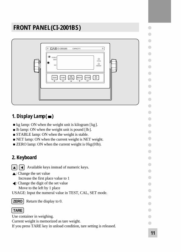
FRONT PANEL(CI-2001BS)
CI-2001BS CAPACITY:
1. Display Lamp( )kg lamp: ON when the weight unit is kilogram [kg].lb lamp: ON when the weight unit is pound [lb].STABLE lamp: ON when the weight is stable.NET lamp: ON when the current weight is NET weight.ZERO lamp: ON when the current weight is 0kg(0lb).
2. Keyboard
Available keys instead of numeric keys.
: Change the set value Increase the first place value to 1
: Change the digit of the set valueMove to the left by 1 place
USAGE: Input the numeral value in TEST, CAL, SET mode.
Return the display to 0.
Use container in weighing.Current weight is memorized as tare weight.If you press TARE key in unload condition, tare setting is released.
ZERO
TARE

12
Display gross and net weight by turn.GROSS lamp on - gross weightNET lamp on - net weightIn case tare weight is REGISTERED, tare and item’s total weight is G. weightand only item’s weight is N. weight.
(CI-2001BS kg only version)
PRINT keyTotal Print key(by pressing “PTINT” key more than 3 second.)
(CI-2001BS kg/lb conversion version)
Toggles between lb and kg units
PRINT key(CI-2001BS kg only version)- Total Print key(by pressing “PRINT” key more than 3 second.)
Total PRINT key(CI-2001BS kg/lb conversion version)HOLD keyLCD manual back light keyIn CALIBRATION, TEST, SET mode.: Store current condition and exit.
3. How to enter TEST modePress the “On/Off” key while pressing the “PRINT” key and TEST mode starts. (CI-2001BS kg only version)Press the “On/Off” key while pressing the “kg/lb” key and TEST mode starts.(CI-2001BS kg/lb conversion version)
4. How to enter SET modePress the “On/Off” key while pressing the “ENTER” key and SET mode starts.
5. How to enter CAL modePress the “On/Off” key while pressing the CAL switch on the rear panel of theindicator and CAL mode starts.
GROSS/NET
ENTER
kg/lb

13
CONNECTING THE CABLE
DC ADAPTER(0V, +12V): Port for DC power.DC 12V adapter is available
RS-485 Interface(485_SIG+, 485_SIG-): Serial interface port.(Computer ...)RS-232 Interface(232_RXD, 232_TXD, GND):Serial interface port.(Computer, Printer, Remote Display)LOAD CELL(Ex+, Ex-, Sig+, Sig-, GND):Port for connecting load cell.
Legal seal installedInstall the seal on the wire loop as shown in below figure.
Cal Switch Plate
Legal SealRear Cover
Sealing Bolt

14
TEST MODE
1. How to EnterPress the power while pressing the “PRINT” key and TEST menu starts.(CI-2001AS/BS kg only version)Press the power while pressing the “kg/lb” key and TEST menu starts.(CI-2001AS/BS kg/lb conversion version)
2. Available KeysIncrease the first place set value to 1.
Move to the left by 1 place of the set value.
Initial(‘0’) of the set value. (CI-2001AS/BS kg type)
Initial(‘0’) of the set value. (CI-2001AS/BS kg/lb)
Move into next menu.
3. TEST Menu(TEST 1 - TEST 5)TEST 1 : Key testTEST 2 : LED/LCD display testTEST 3 : Load cell test and A/D conversion testTEST 4 : Serial interface test(RS-232)TEST 5 : Printer test
TEST 1
Function: Key test
Key Display Description
ENTER: Next menu
Other keys: Performtest
TEST 1 condition.
Press the key to be tested and the No, andcode of the key is displays.
Key mode should be identify with code of key like above.
ENTER( )
kg/lb

15
CI-2001AS/BS kg only version
Key Code
ZERO 2
TARE 3
G/N 4
PRINT 5
ENTER 6
CI-2001AS/BS kg/ lb version
Key Code
ZERO 2
TARE 3
G/N 4
kg/ lb 5
ENTER 6
Key list
TEST 2
Function: LED/LCD display test
Key Display Description
Displaying all lamps of key
TEST 2 condition.
TEST 2 is performed automatically after 3 seconds or so.
Key Display Description
ENTER: Next menu
Other keys: Performtest Digital
convertedvalue
TEST 3 condition.
Display digital value of current weight.This value means converted digital value.
REF 1. Program is automatically shifted to test 3 after completing Test 2.
TEST 3
Function: A/D converter test(L/C test)
REF 1. A/D converter test is automatically completed by displaying converted digital value of current weight.
REF 2. L/C test is also completed by loading the weight on the platform.Check whether digital value is changing.If the digital value is fixed or zero is displayed, please check the connectionof the load cell.

16
Key Display Description
ZERO: Transmit ‘1’TARE: Transmit ‘2’G/N: Transmit ‘3’PRINT: Transmit ‘4’
ENTER: Next menu
TEST 4 condition.
Wait for transmission and reception.
Receive: 1, Transmit: none
Receive: 1, Transmit: 13
TEST 4
Function: RS-232 test with computer
Key Display Description
ENTER: Exit test mode
Other keys: Perform test
TEST 5 condition.
No error in printer.
Check printer connector.
TEST 5
Function: Printer test
REF 1. Do this test after the connection between serial port of computer and serial port of indicator.
REF 2. Send No.1 in computer keyboard and check if indicator receives No.1.Send No.1 in indicator keyboard and check if computer receives No.1.
REF 3. Do this test after baud rate is specified in SET mode(F11).
INDICATOR TEST(when it isn’t connected with PC)
1) Connect directly between No.2(TXD) and No.3(RXD) in indicator of serial port.2) If transmitting data is identical with receiving data by pressing key of front panel,
this test will be done.
REF 1. “GOOD” message is displayed if the printer connection and specification is done correctly. If or not, “ERR 06” message is displayed.
REF 2. The test output format of printer is like follows.
If you press the enter key, it will be returned to NORMAL MODE.However, only when it is connected with printer, this test can be performed.
TEST OK
17
Key Display Description
: Increase of no.: Shift of digit
ENTER: Store and move into next menu
Program version.
CAL 1 condition.
100kg(lb)
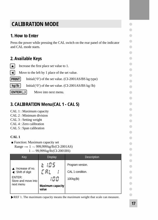
CALIBRATION MODE
1. How to EnterPress the power while pressing the CAL switch on the rear panel of the indicatorand CAL mode starts.
2. Available KeysIncrease the first place set value to 1.
Move to the left by 1 place of the set value.
Initial(‘0’) of the set value. (CI-2001AS/BS kg type)
Initial(‘0’) of the set value. (CI-2001AS/BS kg/lb)
Move into next menu.
3. CALIBRATION Menu(CAL 1 - CAL 5)CAL 1 : Maximum capacityCAL 2 : Minimum divisionCAL 3 : Setting weightCAL 4 : Zero calibrationCAL 5 : Span calibration
CAL 1
Function: Maximum capacity setRange 1 999,999kg/lb(CI-2001AS)
1 99,999kg/lb(CI-2001BS)
ENTER( )
kg/lb
Maximum capacityvalue
REF 1. The maximum capacity means the maximum weight that scale can measure.
18
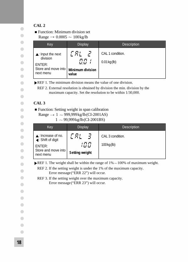
Key Display Description
: Input the nextdivision
ENTER: Store and move into next menu
CAL 1 condition.
0.01kg(lb)
CAL 2
Function: Minimum division setRange 0.0005 100kg/lb
Minimum divisionvalue
Key Display Description
: Increase of no.: Shift of digit
ENTER: Store and move into next menu
CAL 3 condition.
100kg(lb)
Setting weight
REF 1. The minimum division means the value of one division.
REF 2. External resolution is obtained by division the min. division by themaximum capacity. Set the resolution to be within 1/30,000.
CAL 3
Function: Setting weight in span calibrationRange 1 999,999kg/lb(CI-2001AS)
1 99,999kg/lb(CI-2001BS)
REF 1. The weight shall be within the range of 1% 100% of maximum weight.
REF 2. If the setting weight is under the 1% of the maximum capacity.Error message(“ERR 22”) will occur.
REF 3. If the setting weight over the maximum capacity.Error message(“ERR 23”) will occur.

19
CAL 4
Function: Zero calibration
Key Display Description
ENTER: Zero calibration andmove into next menu
CAL 4 condition.
Unload the tray and press ENTER.
Under zero calibration.
Zero calibration is completed.
Key Display Description
ENTER: Span calibration andmove into next menu
CAL 5 condition.
Load the weight which was set in CAL 3 andpress ENTER.
Under span calibration.
Span calibration is completed.
Remove the setting weight.Press the “ENTER” key to save the value.
REF 1. If zero calibration is done without any error, GOOD message is displayed and program moves into CAL 5 automatically.
REF 2. If the “ZERO” key is press, only zero calibration is completed and programmoves SAVE & EXIT mode. Press ENTER key.
CAL 5
Function: Span calibration
REF 1. If span calibration is done without any error, GOOD message is displayed the weight of setting weight is displayed on display screen.Check the weight.
REF 2. If the span is low, error message(ERR 24) is displayed.Calibrate with lower resolution.
REF 3. After setting the exact value, remove the setting weight and press the “ENTER” key to save the value.
20
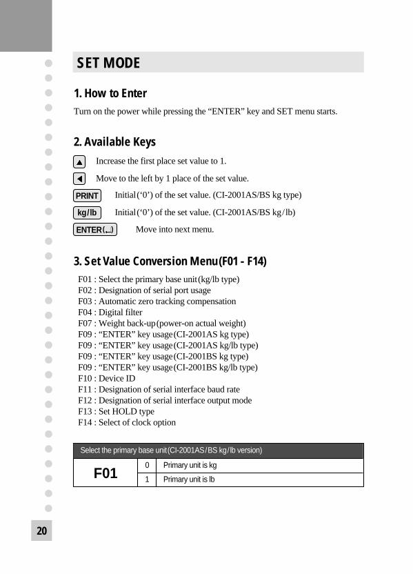
SET MODE
1. How to EnterTurn on the power while pressing the “ENTER” key and SET menu starts.
2. Available KeysIncrease the first place set value to 1.
Move to the left by 1 place of the set value.
Initial(‘0’) of the set value. (CI-2001AS/BS kg type)
Initial(‘0’) of the set value. (CI-2001AS/BS kg/lb)
Move into next menu.
3. Set Value Conversion Menu(F01 - F14)F01 : Select the primary base unit(kg/lb type)F02 : Designation of serial port usageF03 : Automatic zero tracking compensationF04 : Digital filterF07 : Weight back-up(power-on actual weight)F09 : “ENTER” key usage(CI-2001AS kg type)F09 : “ENTER” key usage(CI-2001AS kg/lb type)F09 : “ENTER” key usage(CI-2001BS kg type)F09 : “ENTER” key usage(CI-2001BS kg/lb type)F10 : Device IDF11 : Designation of serial interface baud rateF12 : Designation of serial interface output modeF13 : Set HOLD typeF14 : Select of clock option
ENTER( )
kg/lb
Select the primary base unit(CI-2001AS/BS kg/lb version)
0 Primary unit is kg
1 Primary unit is lbF01
21
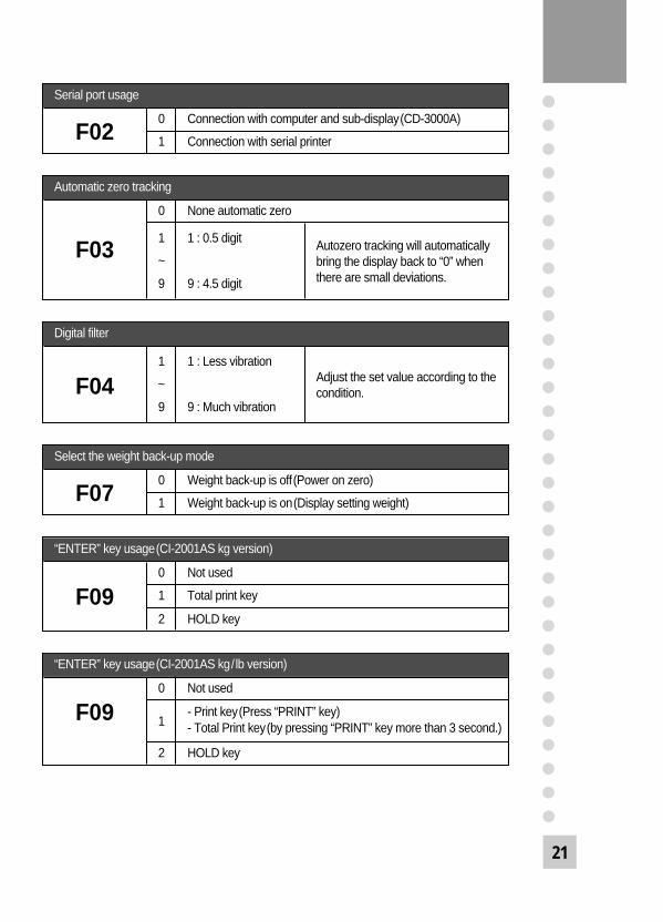
Serial port usage
0 Connection with computer and sub-display(CD-3000A)
1 Connection with serial printerF02
Select the weight back-up mode
0 Weight back-up is off(Power on zero)
1 Weight back-up is on(Display setting weight)F07
“ENTER” key usage(CI-2001AS kg version)
0 Not used
1 Total print key
2 HOLD keyF09
“ENTER” key usage(CI-2001AS kg/lb version)
0 Not used
1- Print key(Press “PRINT” key)- Total Print key(by pressing “PRINT” key more than 3 second.)
2 HOLD key
F09
Automatic zero tracking
0 None automatic zero
1 1 : 0.5 digit
~
9 9 : 4.5 digit
Autozero tracking will automatically bring the display back to “0” when there are small deviations.
F03
Digital filter
1 1 : Less vibration
~
9 9 : Much vibration
Adjust the set value according to thecondition.F04

22
“ENTER” key usage(CI-2001BS kg version)
0 Not used
1 Total print key
2 HOLD key
3 LCD manual back-light key
F09
Baud rate
0 600 bps
1 1200 bps
2 2400 bps
3 4800 bps
4 9600 bps
5 19200 bps
F11
“ENTER” key usage(CI-2001BS kg/lb version)
0 Not used
1- Print key(Press “PRINT” key)- Total Print key(by pressing “PRINT” key more than 3 second.)
2 HOLD key
3 LCD manual back-light key
F09
Device ID
00 00 : Device ID “00”
~
99 99 : Device ID “99”
It is used the no. of indicator whensystem is connected.F10
23
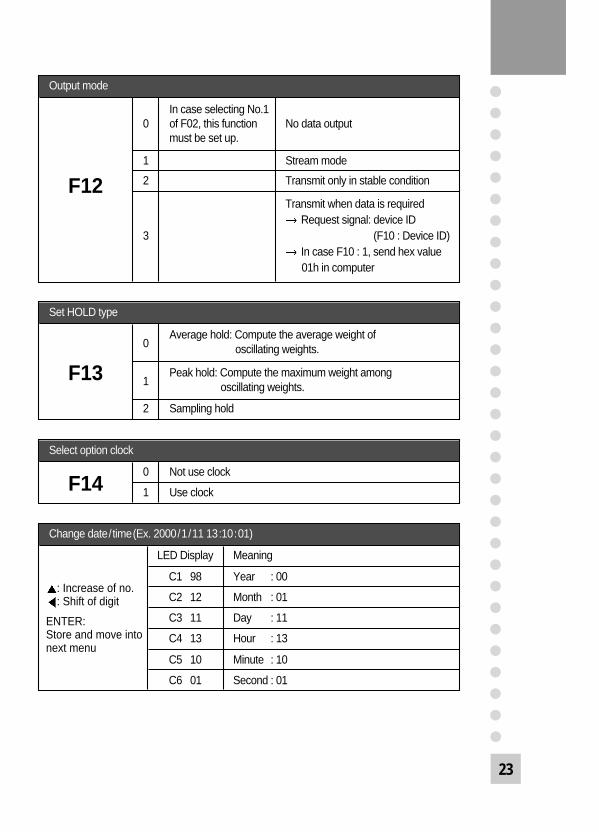
Output mode
In case selecting No.10 of F02, this function No data output
must be set up.
1 Stream mode
2 Transmit only in stable condition
Transmit when data is requiredRequest signal: device ID
3 (F10 : Device ID)In case F10 : 1, send hex value01h in computer
F12
Set HOLD type
0Average hold: Compute the average weight of
oscillating weights.
1Peak hold: Compute the maximum weight among
oscillating weights.
2 Sampling hold
F13
Select option clock
0 Not use clock
1 Use clockF14
Change date/time(Ex. 2000/1/11 13:10:01)
LED Display Meaning
C1 98 Year : 00
C2 12 Month : 01
C3 11 Day : 11
C4 13 Hour : 13
C5 10 Minute : 10
C6 01 Second : 01
: Increase of no.: Shift of digit
ENTER: Store and move into next menu

24
SERIAL INTERFACE
Transmit mode: RS-232C interface
OP-1 RS-232C Serial Interface(COM1)
Sub-display Connection
RXDTXDGND
2 Transmit Data3 Receive Data 7 Signal Ground
9pin port(Male)RS-232C port of sub-display
RS-232C port of CI-2001AS/BS
RXDTXDGND
2 Transmit Data3 Receive Data 7 Signal Ground4 Request To Send 5 Clear To Send6 Data Set Ready 8 Carrier Detect
20 Data Terminal Ready
25pin port(Female)Serial port of computer
RS-232C port of CI-2001AS/BS
RXDTXDGND
3 Transmit Data2 Receive Data 5 Chassis Ground1 Carrier Detect 4 Data Terminal Ready6 Data Set Ready 7 Request to Send8 Clear to Send
9pin port(Female)Serial port of computer
RS-232C port of CI-2001AS/BS

25
Transmit Data Format(22 bytes), , , CR LFData(8 bytes)
US(Unstable)ST(Stable) OL(Over)
GS(Gross)NT(Net)
UNIT
kglb
Device ID
Empty
Device ID Transmit 1 byte device ID so that the receiver can receive data selectivelywhich indicator send.(Device ID is able to set at F10.)
Data(8 bytes) : Weight data with decimal point1. 13.5 kg : ‘0’, ‘0’, ‘0’, ‘0’, ‘1’, ‘3’, ‘.’, ‘5’2. 135 kg : ‘0’, ‘0’, ‘0’, ‘0’, ‘1’, ‘3’, ‘5’, ‘0’3. -135 kg : ‘-’, ‘0’, ‘0’, ‘0’, ‘1’, ‘3’, ‘5’, ‘0’Each ASCII code of weight transmitted by 8 byte.(‘0’ : 0 20)
Simple Interface Program(Language : BASIC)
10 OPEN “COM1:9600,N,8,1” As #120 IF LOC(1) = 0 THEN 6030 A$ = INPUT$(1,1)40 PRINT A$ ; “ ”;50 GOTO 2060 B$=INKEY$ : IF B$ =“ ” THEN 2070 PRINT B$ ; “ ”;80 PRINT #1,B$;90 GOTO 20
26
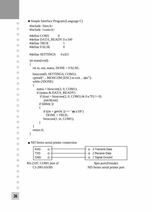
Simple Interface Program(Language C)
#include <bios.h>#include <conio.h>
#define COM1 0#define DATA_READY 0 100#define TRUE 1#define FALSE 0
#define SETTINGS 0 E3
int main(void) {
int in, out, status, DONE = FALSE;
bioscom(0, SETTINGS, COM1); cprintf(“... BIOSCOM [ESC] to exit ... n”);while (!DONE) {
status = bioscom(3, 0, COM1);if (status & DATA_READY)
if ((out = bioscom(2, 0, COM1) & 0 7F) != 0) putch(out);
if (kbhit( )) {
if ((in = getch( )) == ‘ 1B’) DONE = TRUE;
bioscom(1, in, COM1); }
}return 0;
}
ND Series serial printer connection
RXDTXDGND
3 Transmit Data2 Receive Data 7 Signal Ground
9pin port(Female)ND Series serial printer port
RS-232C COM1 port of CI-2001AS/BS

27
Transmit mode: Same as RS-232C interface COM1
Data format: Same as RS-232C interface COM1
Connecting method of RS-485 port
Connecting method of RS-485 remote sub display
Option RS-422/485 Serial Interface(COM1)
485(+)485(-)
GND
2 Transmit Data(+)15 Receive Data(-) 14 Transmit Data(-)3 Receive Data(+) 1 Ground7 Ground 4, 5 Wire connect16, 17 Wire connect
Serial port of device
RS-485 port of CI-2001AS/BS
485(+)485(-)
GND
6 Transmit Data(+)5 Receive Data(-) 4 Transmit Data(-)1 Receive Data(+) 7 Ground
RS-485 port of sub displayRS-485 port of CI-2001AS/BS
28
ERROR MESSAGE & TROUBLE SHOOTING
1. Errors in Weighing ModeErr 02
Reason: Load cell connection failure or error in A/D conversion part.Trouble shooting: Check the load cell connector to see if the polarity of signal
is reversed.
Err 06Reason: Error in printer connection Trouble shooting: Check with printer connector.
If there is no problem with printer and printer connector,please request A/S to head office.
Err 08Reason: The ZERO key or TARE key is adjusted not to be operated under the
unstable condition. Trouble shooting: Press zero or tare key in stable condition.
Err 10Reason: Tare weight exceeds the maximum capacity of the scale. Trouble shooting: Set the tare to be smaller than the maximum capacity.
Otherwise the maximum capacity is reset to be larger than the tare to be set in the calibration menu, and reset the calibration using weight.
Err 13Reason: The zero range deviates from the set range. Trouble shooting: Confirm that there is nothing on the weighing platform.
If nothing exist, do calibration in CAL mode.
OverReason: The weight on platform is too heavy to be measured. Trouble shooting: Do not load the item exceeds the maximum tolerance.
If the load cell is damaged, the load cell should be replace.

29
2. Errors in Calibration ModeErr 21
Reason: The resolution is set to be exceeded the limit 1/50,000.Trouble shooting: Lower the resolution.
The resolution = allowed weight/one divisionModify the allowed weight in CAL 1 or modify the divisionin CAL 2 so that the resolution should be below 1/50,000.
Err 22Reason: The weight for span calibration is set to be lower than 1% of the
maximum capacity of the scale. Trouble shooting: Set the weight for span calibration in CAL 3 to be more than
10% of the maximum capacity.
Err 23Reason: The weight for span calibration is set to be exceeded 100% of the
maximum capacity of the scale. Trouble shooting: Set the weight for span calibration to be within the
maximum capacity of the scale in CAL 1.
Err 24Reason: The load cell output is too small at SPAN calibration. Trouble shooting: Setting of current resolution is not possible due to the error
in load cell. Proceed calibration again with less resolution.
Load cell sense voltage for 5V excitation voltage Recommended resolution
2mV 1/1,000
4mV 1/2,000
10mV 1/5,000
Err 25Reason: The load cell output is too large at SPAN calibration.Trouble shooting: Setting of current resolution is not possible due to the error
in load cell. Proceed calibration again with less resolution.
30
Err 26Reason: The load cell output is too large at ZERO calibration. Trouble shooting: Check whether the platform empty.
Proceed calibration again after checking in A/D TEST mode.