Embed Size (px)
Citation preview
WEG Welcomes
For
Presentation on
Quality aspects of Hydro-Generators
Date: 06.01.2018
0

Our History September 16th, 1961
Back in 1961, Werner Ricardo
Voigt, Eggon João da Silva and
Geraldo Werninghaus decided to
join efforts to create a company.
Werner Ricardo Voigt
Eggon Joao da Silva
Geraldo Werninghaus
These men did not just create a
company. They created a
complete culture of doing
business that is focused on
people.
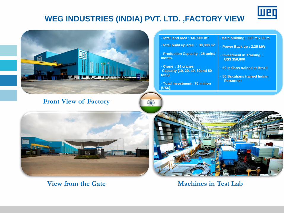
WEG INDUSTRIES (INDIA) PVT. LTD. ,FACTORY VIEW
-Total land area : 146,500 m2
-Total build up area : 30,000 m2
- Production Capacity : 25 units/
month.
- Crane : 14 cranes
Capacity (10, 20, 40, 60and 80
tons)
- Total Investment : 70 million
(US$)
-Main building : 300 m x 65 m
- Power Back up : 2.25 MW
- Investment in Training :
US$ 350,000
- 50 Indians trained at Brazil
- 50 Brazilians trained Indian
Personnel
Front View of Factory
View from the Gate Machines in Test Lab
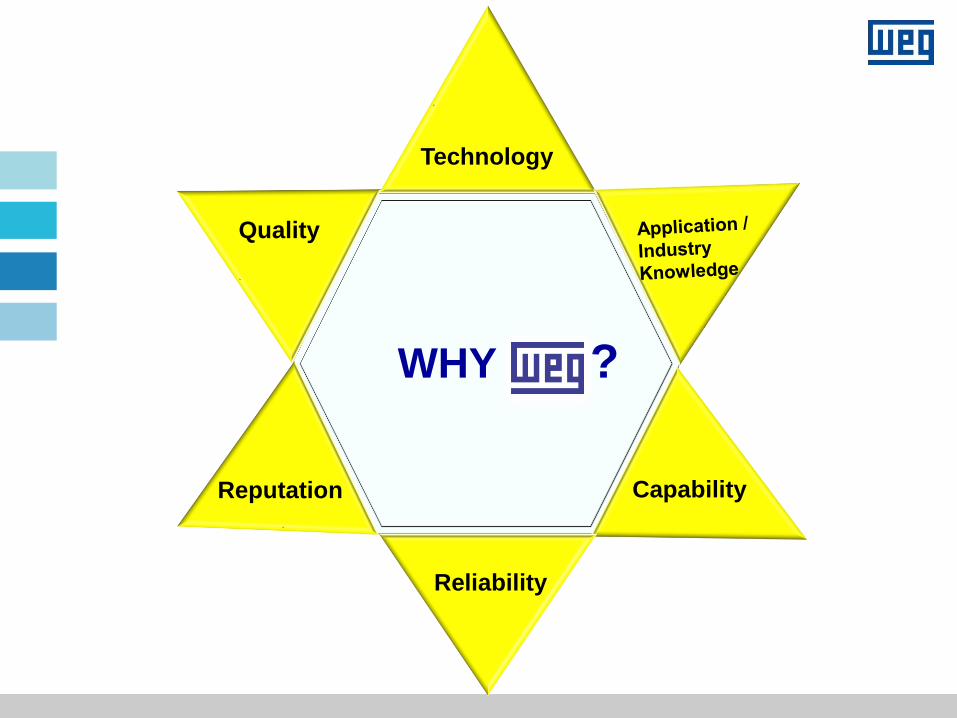
WHY ?
v
Technology
Capability
Reliability
Reputation
Quality
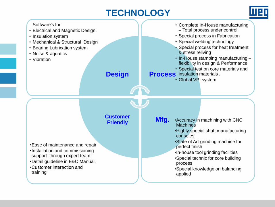
Customer Friendly
Design
Mfg.
Process
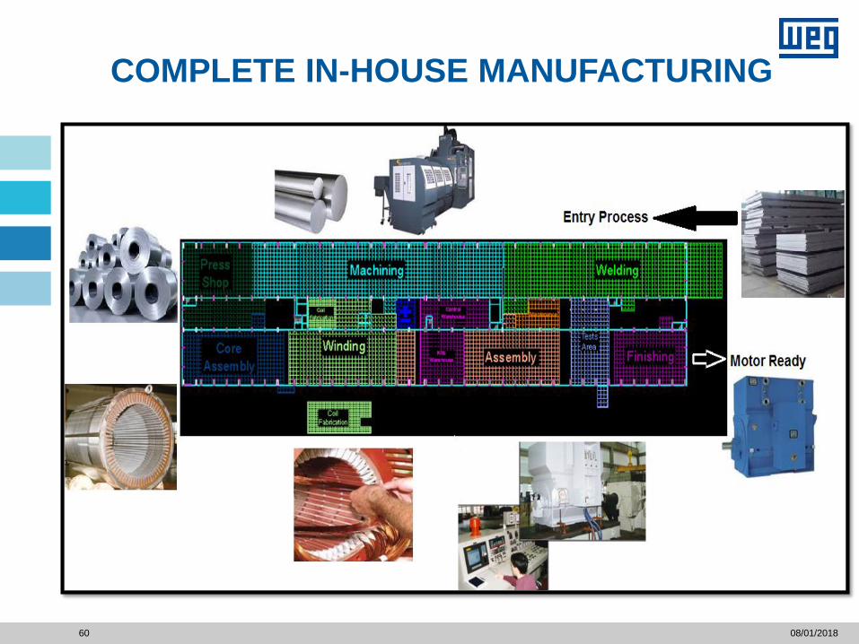
• Complete In-House manufacturing – Total process under control.
• Special process in Fabrication
• Special welding technology
• Special process for heat treatment & stress reliving
• In-House stamping manufacturing – flexibility in design & Performance.
• Special test on core materials and insulation materials .
• Global VPI system
•Accuracy in machining with CNC Machines
•Highly special shaft manufacturing consoles
•State of Art grinding machine for perfect finish
•In-house tool grinding facilities
•Special technic for core building process
•Special knowledge on balancing applied
•Ease of maintenance and repair
•Installation and commissioning support through expert team
•Detail guideline in E&C Manual.
•Customer interaction and training
• Software's for
• Electrical and Magnetic Design.
• Insulation system
• Mechanical & Structural Design
• Bearing Lubrication system
• Noise & aquatics
• Vibration
TECHNOLOGY
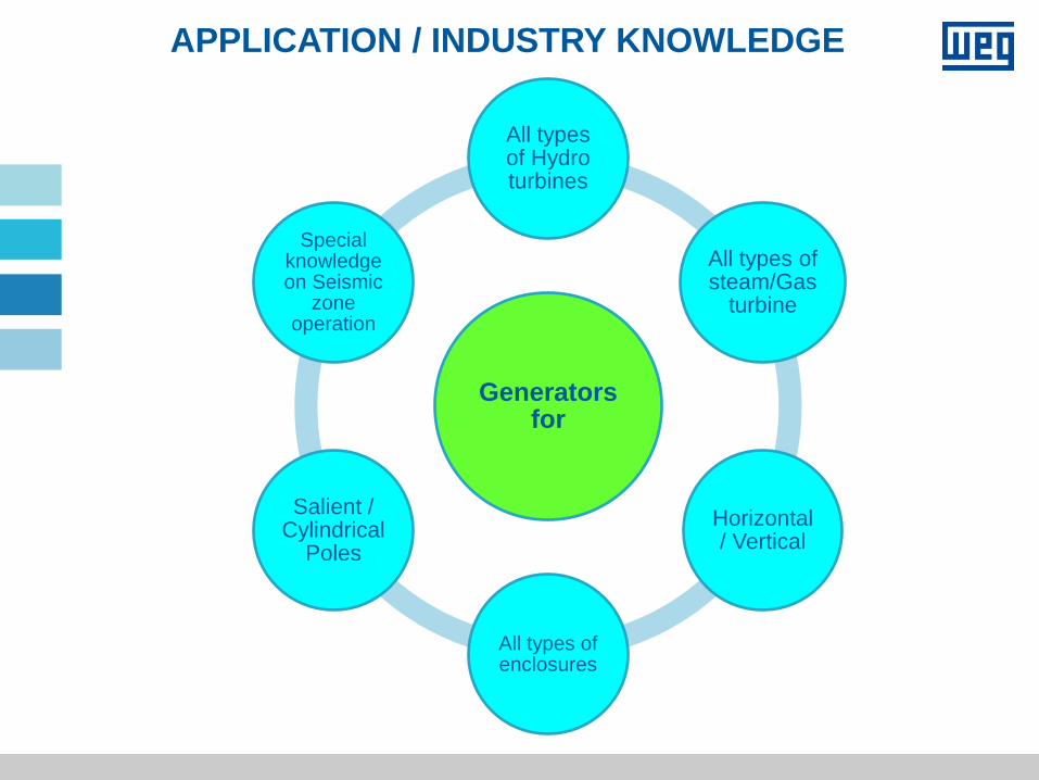
APPLICATION / INDUSTRY KNOWLEDGE
Generators for
All types of Hydro turbines
All types of steam/Gas
turbine
Horizontal / Vertical
All types of enclosures
Salient / Cylindrical
Poles
Special knowledge on Seismic
zone operation
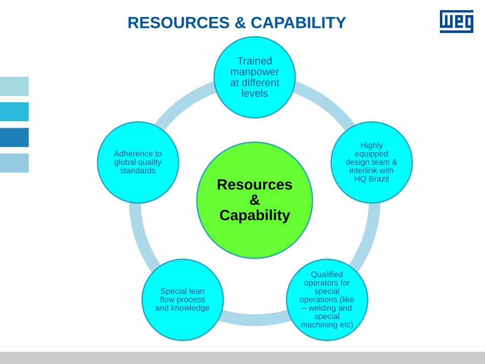
RESOURCES & CAPABILITY
Resources &
Capability
Trained manpower at different
levels
Highly equipped
design team & interlink with
HQ Brazil
Qualified operators for
special operations (like – welding and
special machining etc)
Special lean flow process
and knowledge
Adherence to global quality
standards
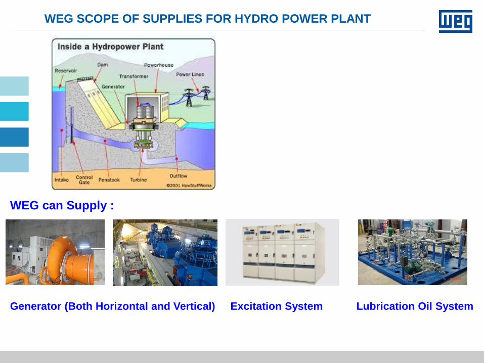
WEG SCOPE OF SUPPLIES FOR HYDRO POWER PLANT
WEG can Supply :
Generator (Both Horizontal and Vertical) Excitation System Lubrication Oil System
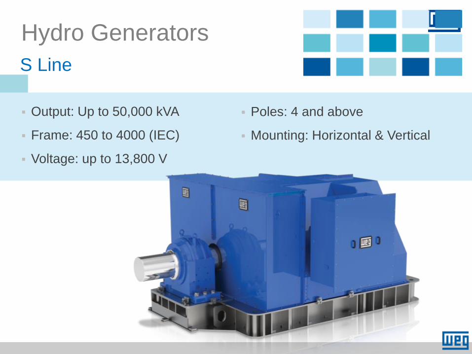
Output: Up to 50,000 kVA
Frame: 450 to 4000 (IEC)
Voltage: up to 13,800 V
Hydro Generators
S Line
Poles: 4 and above
Mounting: Horizontal & Vertical

TECHNOLOGY APPLIED TO
ENGINEERING/DESIGN
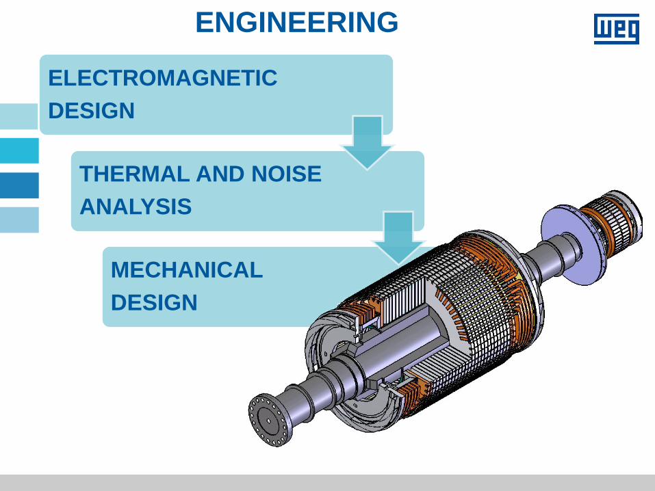
ENGINEERING
ELECTROMAGNETIC
DESIGN
THERMAL AND NOISE
ANALYSIS
MECHANICAL
DESIGN
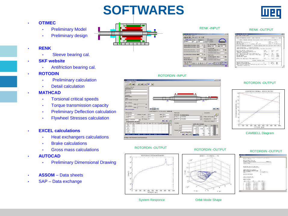
SOFTWARES • OTIMEC
• Preliminary Model
• Preliminary design
• RENK
• Sleeve bearing cal.
• SKF website
• Antifriction bearing cal.
• ROTODIN
• Preliminary calculation
• Detail calculation
• MATHCAD
• Torsional critical speeds
• Torque transmission capacity
• Preliminary Deflection calculation
• Flywheel Stresses calculation
• EXCEL calculations
• Heat exchangers calculations
• Brake calculations
• Gross mass calculations
• AUTOCAD
• Preliminary Dimensional Drawing
• ASSOM – Data sheets
• SAP – Data exchange
ROTORDIN -INPUT
RENK -OUTPUT RENK -INPUT
CAMBELL Diagram
ROTORDIN -OUTPUT
System Responce
ROTORDIN -OUTPUT
Orbit-Mode Shape
ROTORDIN -OUTPUT ROTORDIN -OUTPUT
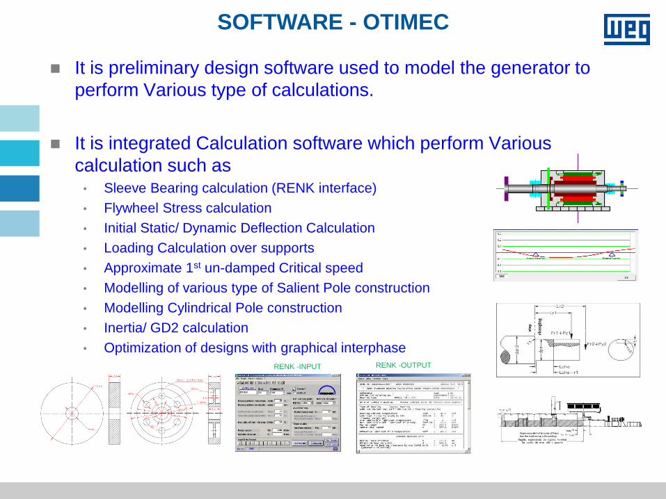
SOFTWARE - OTIMEC
It is preliminary design software used to model the generator to
perform Various type of calculations.
It is integrated Calculation software which perform Various
calculation such as • Sleeve Bearing calculation (RENK interface)
• Flywheel Stress calculation
• Initial Static/ Dynamic Deflection Calculation
• Loading Calculation over supports
• Approximate 1st un-damped Critical speed
• Modelling of various type of Salient Pole construction
• Modelling Cylindrical Pole construction
• Inertia/ GD2 calculation
• Optimization of designs with graphical interphase
RENK -INPUT RENK -OUTPUT
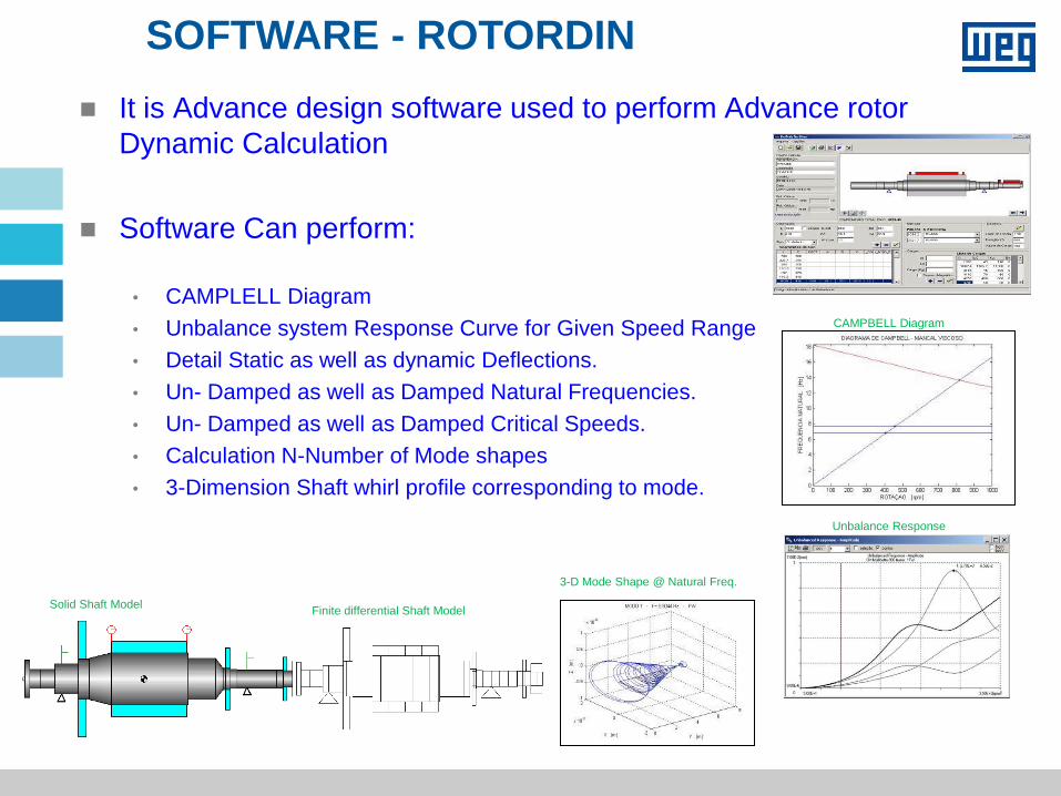
SOFTWARE - ROTORDIN
It is Advance design software used to perform Advance rotor
Dynamic Calculation
Software Can perform:
• CAMPLELL Diagram
• Unbalance system Response Curve for Given Speed Range
• Detail Static as well as dynamic Deflections.
• Un- Damped as well as Damped Natural Frequencies.
• Un- Damped as well as Damped Critical Speeds.
• Calculation N-Number of Mode shapes
• 3-Dimension Shaft whirl profile corresponding to mode.
CAMPBELL Diagram
Unbalance Response
Solid Shaft Model Finite differential Shaft Model
3-D Mode Shape @ Natural Freq.
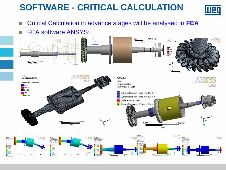
SOFTWARE - CRITICAL CALCULATION Critical Calculation in advance stages will be analysed in FEA
FEA software ANSYS:

TECHNOLOGY APPLIED TO
ELECTROMAGNETIC ANALYSIS
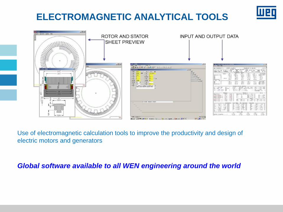
Engineering ELECTROMAGNETIC ANALYTICAL TOOLS
Use of electromagnetic calculation tools to improve the productivity and design of
electric motors and generators
Global software available to all WEN engineering around the world
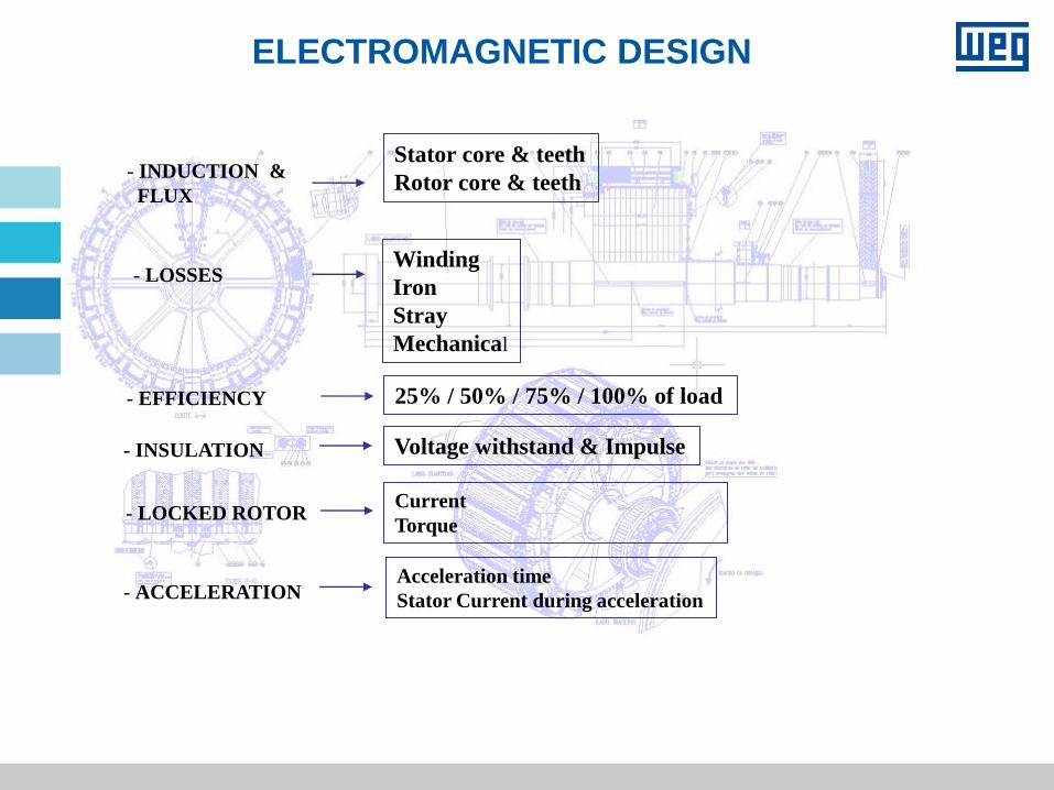
- INDUCTION &
FLUX
Stator core & teeth
Rotor core & teeth
- EFFICIENCY 25% / 50% / 75% / 100% of load
- LOSSES Winding
Iron
Stray
Mechanical
- INSULATION Voltage withstand & Impulse
ELECTROMAGNETIC DESIGN
- LOCKED ROTOR Current
Torque
- ACCELERATION Acceleration time
Stator Current during acceleration
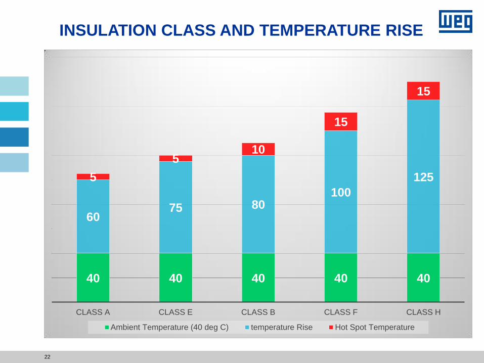
40 40 40 40 40
60 75 80
100
125 5
5 10
15
15
CLASS A CLASS E CLASS B CLASS F CLASS H
Ambient Temperature (40 deg C) temperature Rise Hot Spot Temperature
22
INSULATION CLASS AND TEMPERATURE RISE
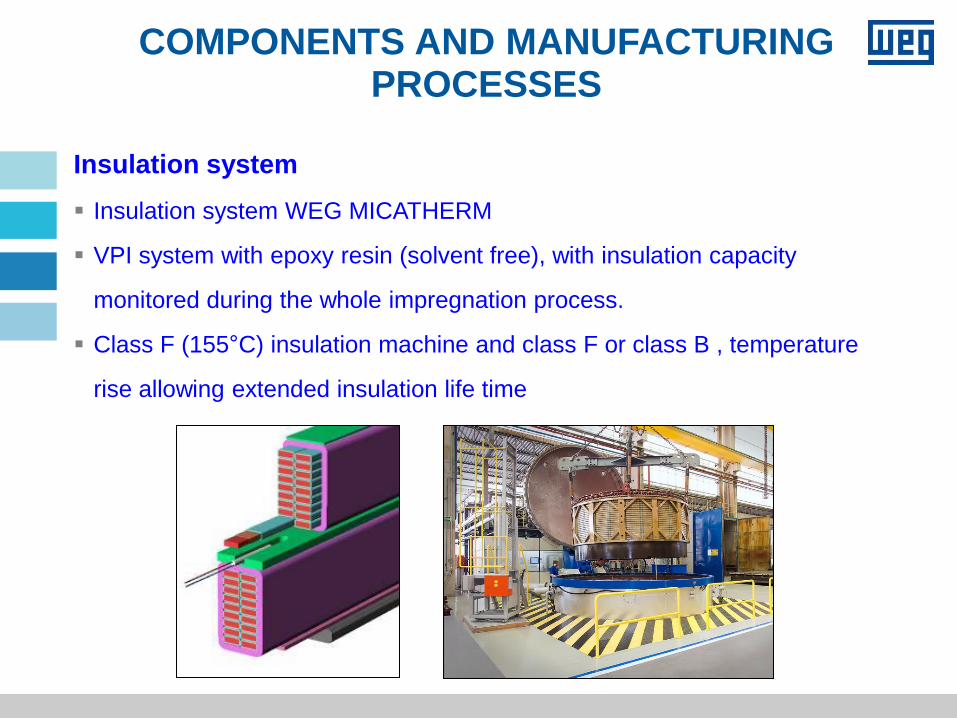
Insulation system
Insulation system WEG MICATHERM
VPI system with epoxy resin (solvent free), with insulation capacity
monitored during the whole impregnation process.
Class F (155°C) insulation machine and class F or class B , temperature
rise allowing extended insulation life time
COMPONENTS AND MANUFACTURING PROCESSES
25
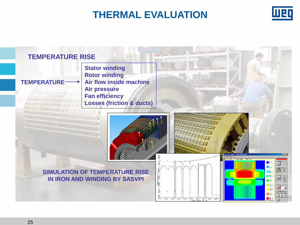
THERMAL EVALUATION
TEMPERATURE RISE
SIMULATION OF TEMPERATURE RISE
IN IRON AND WINDING BY SASVPI
TEMPERATURE
Stator winding
Rotor winding
Air flow inside machine
Air pressure
Fan efficiency
Losses (friction & ducts)
TECHNOLOGY APPLIED TO
MECHANICAL DESIGN
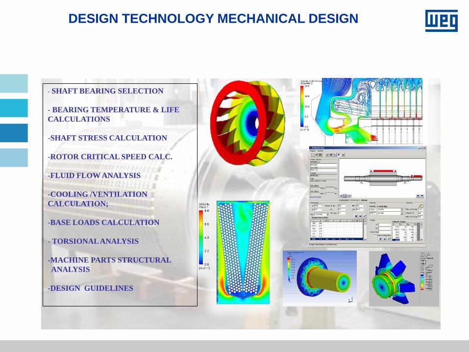
DESIGN TECHNOLOGY MECHANICAL DESIGN
- SHAFT BEARING SELECTION
- BEARING TEMPERATURE & LIFE
CALCULATIONS
-SHAFT STRESS CALCULATION
-ROTOR CRITICAL SPEED CALC.
-FLUID FLOW ANALYSIS
-COOLING /VENTILATION
CALCULATION;
-BASE LOADS CALCULATION
- TORSIONAL ANALYSIS
-MACHINE PARTS STRUCTURAL
ANALYSIS
-DESIGN GUIDELINES
28
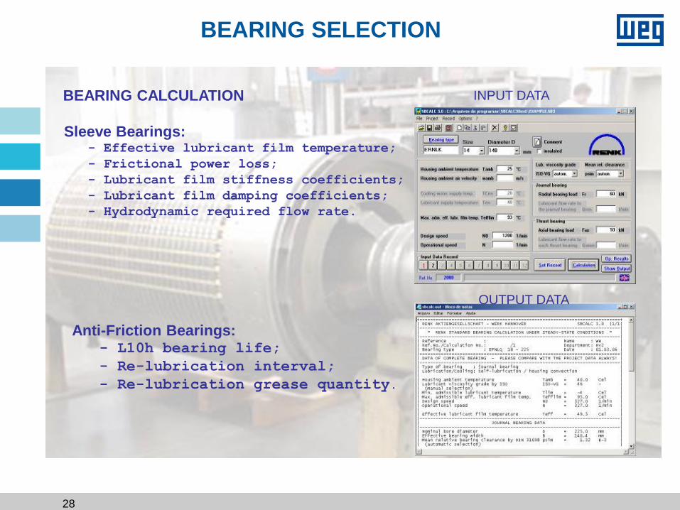
BEARING CALCULATION
Sleeve Bearings: - Effective lubricant film temperature;
- Frictional power loss;
- Lubricant film stiffness coefficients;
- Lubricant film damping coefficients;
- Hydrodynamic required flow rate.
INPUT DATA
OUTPUT DATA
Anti-Friction Bearings: - L10h bearing life;
- Re-lubrication interval;
- Re-lubrication grease quantity.
BEARING SELECTION
29
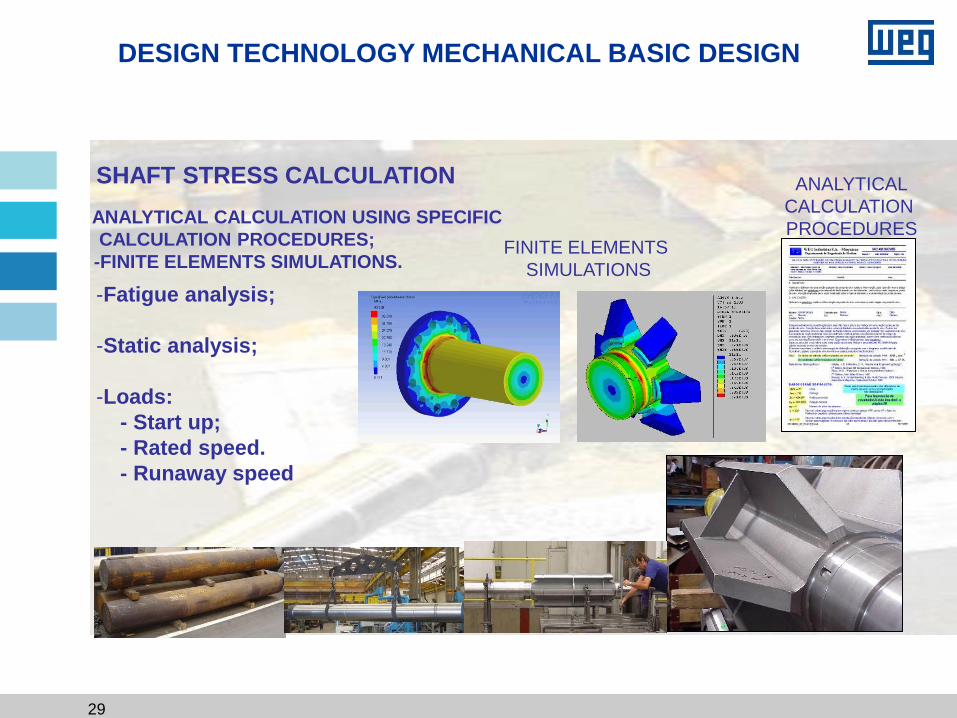
DESIGN TECHNOLOGY MECHANICAL BASIC DESIGN
SHAFT STRESS CALCULATION
-Fatigue analysis;
-Static analysis;
-Loads:
- Start up;
- Rated speed.
- Runaway speed
ANALYTICAL
CALCULATION
PROCEDURES -ANALYTICAL CALCULATION USING SPECIFIC
CALCULATION PROCEDURES;
-FINITE ELEMENTS SIMULATIONS. FINITE ELEMENTS
SIMULATIONS
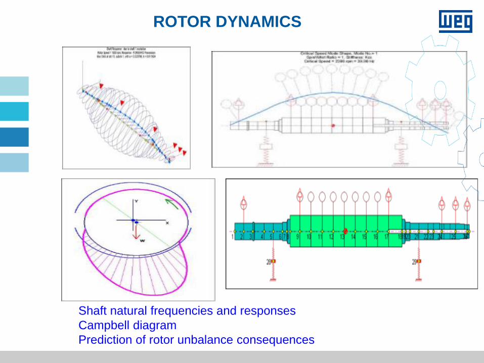
ROTOR DYNAMICS
Shaft natural frequencies and responses
Campbell diagram
Prediction of rotor unbalance consequences
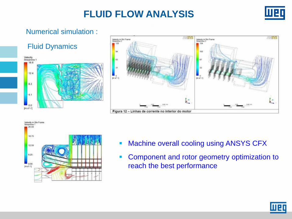
Fluid Dynamics
Numerical simulation :
Machine overall cooling using ANSYS CFX
Component and rotor geometry optimization to
reach the best performance
FLUID FLOW ANALYSIS
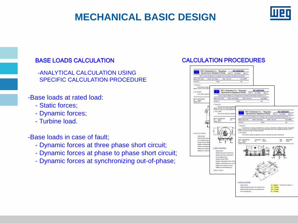
MECHANICAL BASIC DESIGN
BASE LOADS CALCULATION
-Base loads at rated load:
- Static forces;
- Dynamic forces;
- Turbine load.
-Base loads in case of fault;
- Dynamic forces at three phase short circuit;
- Dynamic forces at phase to phase short circuit;
- Dynamic forces at synchronizing out-of-phase;
CALCULATION PROCEDURES
-ANALYTICAL CALCULATION USING
SPECIFIC CALCULATION PROCEDURE
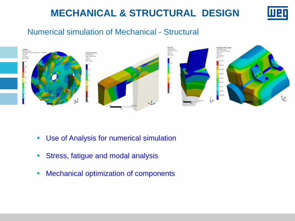
MECHANICAL & STRUCTURAL DESIGN
Use of Analysis for numerical simulation
Stress, fatigue and modal analysis
Mechanical optimization of components
Numerical simulation of Mechanical - Structural
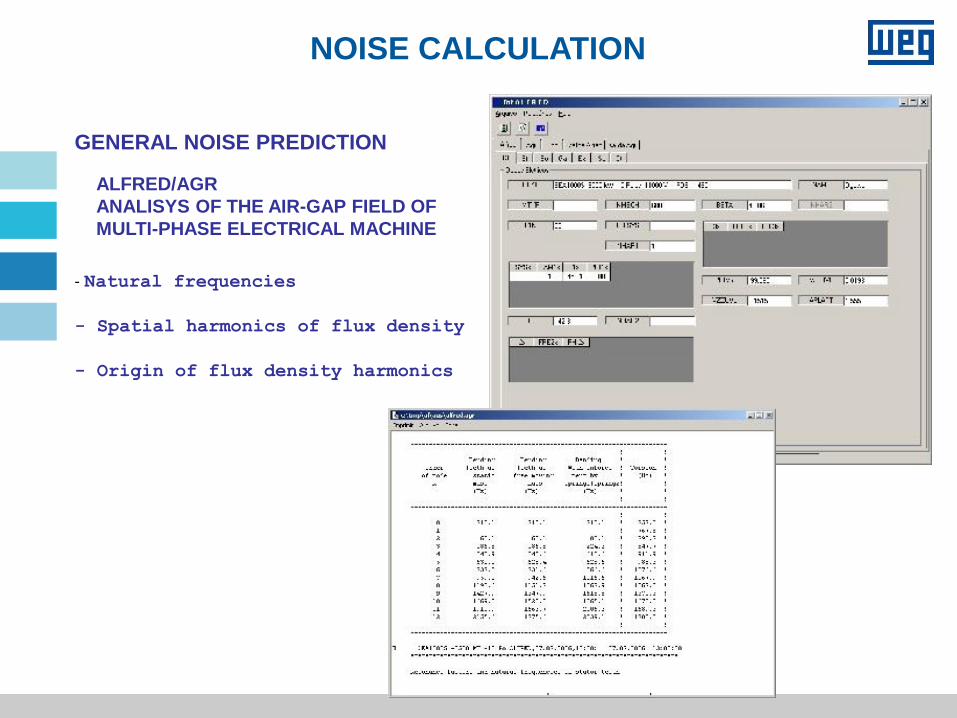
NOISE CALCULATION
ALFRED/AGR
ANALISYS OF THE AIR-GAP FIELD OF
MULTI-PHASE ELECTRICAL MACHINE
GENERAL NOISE PREDICTION
- Natural frequencies
- Spatial harmonics of flux density
- Origin of flux density harmonics
35
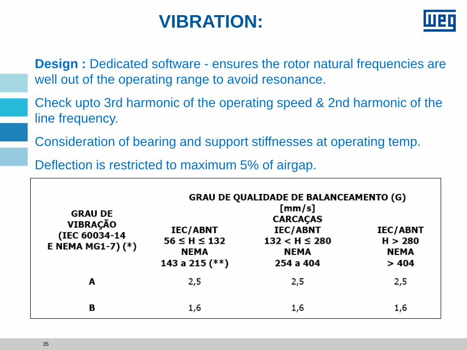
Design : Dedicated software - ensures the rotor natural frequencies are
well out of the operating range to avoid resonance.
Check upto 3rd harmonic of the operating speed & 2nd harmonic of the
line frequency.
Consideration of bearing and support stiffnesses at operating temp.
Deflection is restricted to maximum 5% of airgap.
VIBRATION:

TECHNOLOGY FOCUS
ON
INERTIA
Synchronous Motor
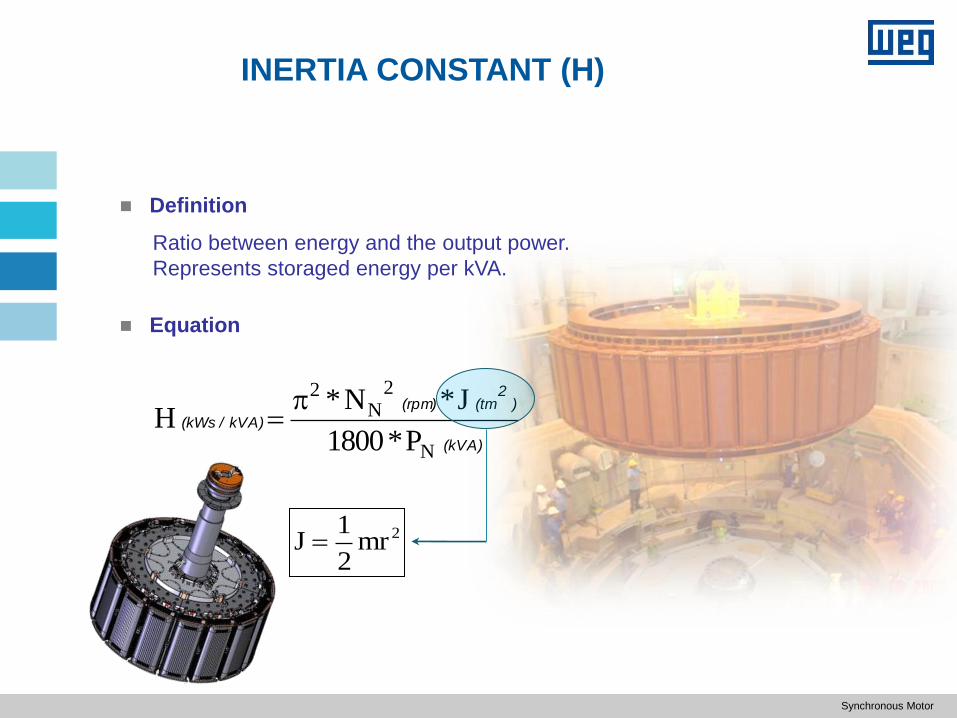
INERTIA CONSTANT (H)
Definition
(kVA)
)2
(tm(rpm)
kVA) /(kWs
N
2N
2
P*1800
J*N*H
2mr2
1J
Equation
Ratio between energy and the output power.
Represents storaged energy per kVA.
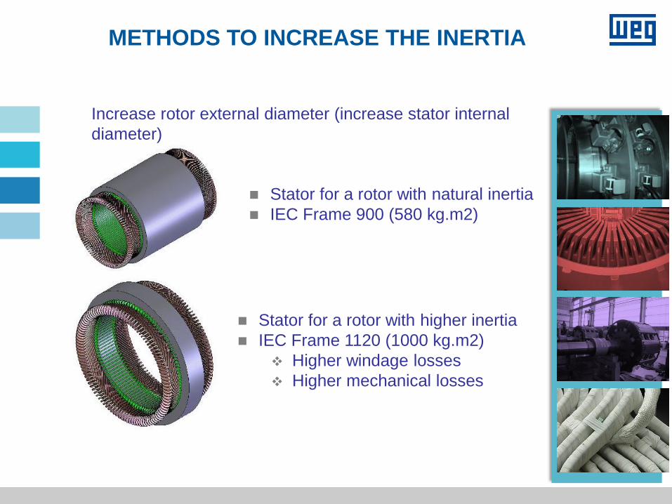
METHODS TO INCREASE THE INERTIA
Increase rotor external diameter (increase stator internal
diameter)
Stator for a rotor with natural inertia
IEC Frame 900 (580 kg.m2)
Stator for a rotor with higher inertia
IEC Frame 1120 (1000 kg.m2)
Higher windage losses
Higher mechanical losses

TECHNOLOGY APPLIED TO
ELECTRICAL DESIGN
RATING AND GENERATOR SIZING
Generator Rating: Generators are rated in KVA and power factor.
This needs special consideration.
Speed: The speed of generator is decided by turbine speed or type
of turbine.
FACTORS AFFECTING GENERATOR SIZE :
Power output (kVA): Generator size will increase with power output
to maintain the magnetic and electric loading.
Speed: Lower the speed of the machine bigger is the size delivering
same power.
Altitude: Machines installed at higher altitude will increase size of
the machine since altitude will effect cooling
Inertia: Higher inertia requirement to improve stability will lead to
higher mass and higher is the machine size
Power Factor: Poor power factor requires higher field input due to
the effect of armature reaction and bigger size of field coils
GENERATOR OVERLOAD
The continuous over load of the generator will increase temperature
rise , so need to limit thermal.
Continuous over load is indicated by service factor
Performance of the machine is offered at rated conditions but thermal
is limited considering the overload.
Short circuit ratio is achieved at rated conditions, as SCR drops at
overload.
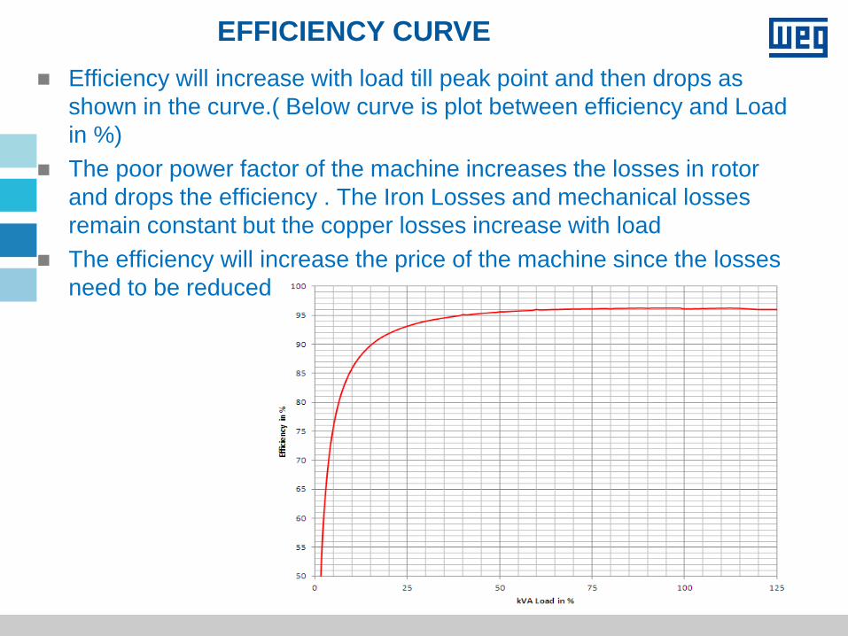
EFFICIENCY CURVE
Efficiency will increase with load till peak point and then drops as
shown in the curve.( Below curve is plot between efficiency and Load
in %)
The poor power factor of the machine increases the losses in rotor
and drops the efficiency . The Iron Losses and mechanical losses
remain constant but the copper losses increase with load
The efficiency will increase the price of the machine since the losses
need to be reduced
SHORT CIRCUIT RATIO REQUIREMENT:
Advantages of higher SCR value:
• The generator will have a more stable operation when connected to the grid
• Better voltage regulation
• Lower noise
Effects of higher SCR value:
• The machine should be designed with a higher air gap, increasing the size
and cost of the machine
• Higher short circuit currents
• Higher temperatures in the rotor leading to increased copper quantity
Synchronous Motor
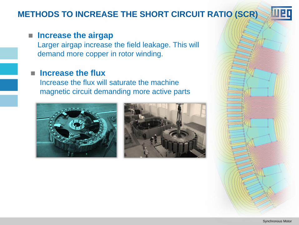
Increase the airgap Larger airgap increase the field leakage. This will
demand more copper in rotor winding.
METHODS TO INCREASE THE SHORT CIRCUIT RATIO (SCR)
Increase the flux Increase the flux will saturate the machine
magnetic circuit demanding more active parts
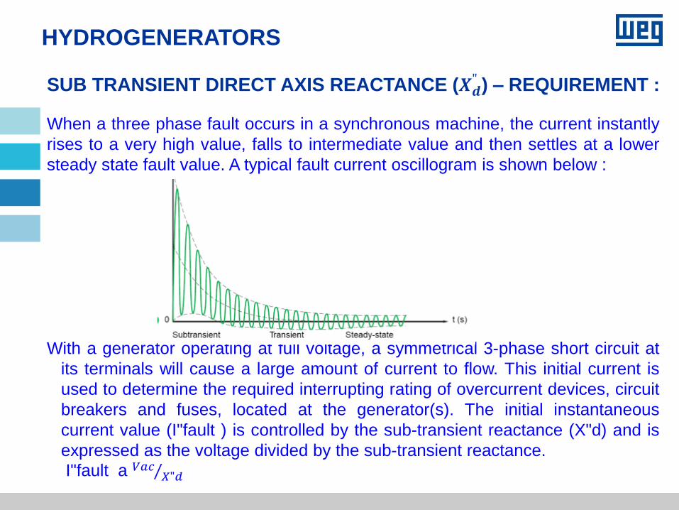
SUB TRANSIENT DIRECT AXIS REACTANCE (𝑿𝒅" ) – REQUIREMENT :
HYDROGENERATORS
When a three phase fault occurs in a synchronous machine, the current instantly
rises to a very high value, falls to intermediate value and then settles at a lower
steady state fault value. A typical fault current oscillogram is shown below :
With a generator operating at full voltage, a symmetrical 3-phase short circuit at
its terminals will cause a large amount of current to flow. This initial current is
used to determine the required interrupting rating of overcurrent devices, circuit
breakers and fuses, located at the generator(s). The initial instantaneous
current value (I"fault ) is controlled by the sub-transient reactance (X"d) and is
expressed as the voltage divided by the sub-transient reactance.
I"fault a 𝑉𝑎𝑐 𝑋"𝑑
COST - EFFECTIVE DESIGN
Natural Inertia :
Double-check power system stability studies to request
natural H, Large inertia increase the generator frame
Natural SCR :
High SCR increase the generator active parts or oversize
the copper
TECHNOLOGY APPLIED TO
PROCESSES
60 08/01/2018
COMPLETE IN-HOUSE MANUFACTURING
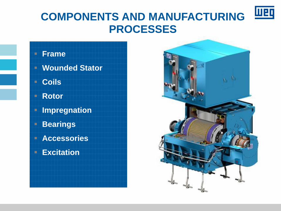
COMPONENTS AND MANUFACTURING PROCESSES
Frame
Wounded Stator
Coils
Rotor
Impregnation
Bearings
Accessories
Excitation
COMPONENTS AND MANUFACTURING PROCESSES
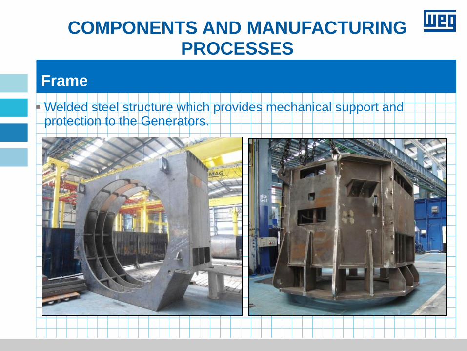
Welded steel structure which provides mechanical support and protection to the Generators.
Frame
COMPONENTS AND MANUFACTURING PROCESSES
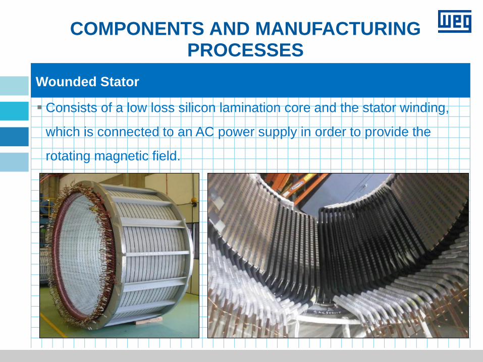
Consists of a low loss silicon lamination core and the stator winding,
which is connected to an AC power supply in order to provide the
rotating magnetic field.
Wounded Stator

COMPONENTS AND MANUFACTURING PROCESSES
Coils
Manufactured with rectangular copper wires, using an automatic process
Insulated with mica tape, semi-conductive and conductive tapes
Impregnated with epoxy resin (without solvent) through VPI system (WEG micatherm
system)
Inserted into the core slots and fixed with fiber glass or magnetic wedges;
The high potential test and short circuit between turns test (surge test) are performed
before and after the stator impregnation process
COMPONENTS AND MANUFACTURING PROCESSES
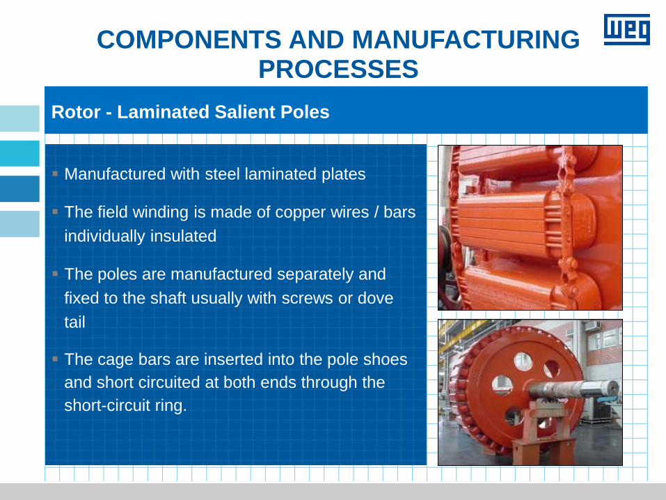
Rotor - Laminated Salient Poles
Manufactured with steel laminated plates
The field winding is made of copper wires / bars
individually insulated
The poles are manufactured separately and
fixed to the shaft usually with screws or dove
tail
The cage bars are inserted into the pole shoes
and short circuited at both ends through the
short-circuit ring.
COMPONENTS AND MANUFACTURING PROCESSES
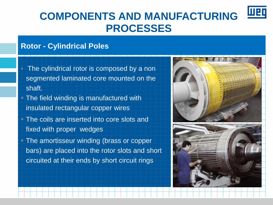
Rotor - Cylindrical Poles
The cylindrical rotor is composed by a non
segmented laminated core mounted on the
shaft.
The field winding is manufactured with
insulated rectangular copper wires
The coils are inserted into core slots and
fixed with proper wedges
The amortisseur winding (brass or copper
bars) are placed into the rotor slots and short
circuited at their ends by short circuit rings
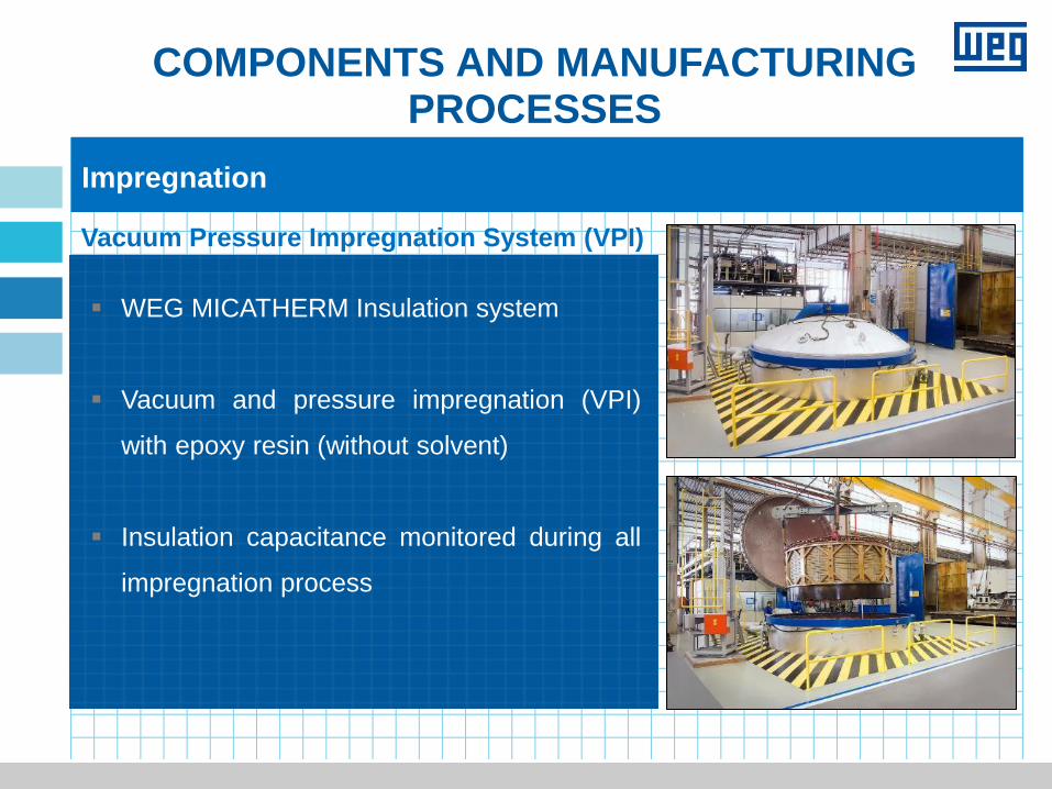
COMPONENTS AND MANUFACTURING PROCESSES
Impregnation
Vacuum Pressure Impregnation System (VPI)
WEG MICATHERM Insulation system
Vacuum and pressure impregnation (VPI)
with epoxy resin (without solvent)
Insulation capacitance monitored during all
impregnation process
COMPONENTS AND MANUFACTURING PROCESSES
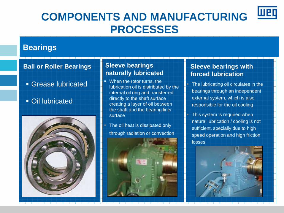
Bearings
Ball or Roller Bearings
Grease lubricated
Oil lubricated
Ball or Roller Bearings Sleeve bearings
naturally lubricated Sleeve bearings with
forced lubrication
Grease lubricated
Oil lubricated
When the rotor turns, the
lubrication oil is distributed by the
internal oil ring and transferred
directly to the shaft surface
creating a layer of oil between
the shaft and the bearing liner
surface
The oil heat is dissipated only
through radiation or convection
The lubricating oil circulates in the
bearings through an independent
external system, which is also
responsible for the oil cooling
This system is required when
natural lubrication / cooling is not
sufficient, specially due to high
speed operation and high friction
losses
COMPONENTS AND MANUFACTURING PROCESSES
Ball or Roller Bearings
Grease lubricated
Oil lubricated
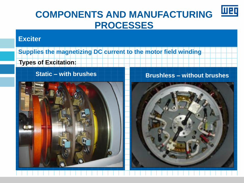
Exciter
Supplies the magnetizing DC current to the motor field winding
Types of Excitation:
Static – with brushes
Brushless – without brushes
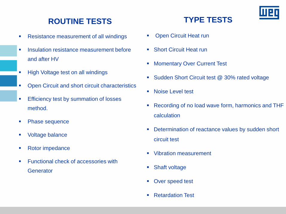
ROUTINE TESTS
Resistance measurement of all windings
Insulation resistance measurement before
and after HV
High Voltage test on all windings
Open Circuit and short circuit characteristics
Efficiency test by summation of losses
method.
Phase sequence
Voltage balance
Rotor impedance
Functional check of accessories with
Generator
TYPE TESTS
Open Circuit Heat run
Short Circuit Heat run
Momentary Over Current Test
Sudden Short Circuit test @ 30% rated voltage
Noise Level test
Recording of no load wave form, harmonics and THF
calculation
Determination of reactance values by sudden short
circuit test
Vibration measurement
Shaft voltage
Over speed test
Retardation Test
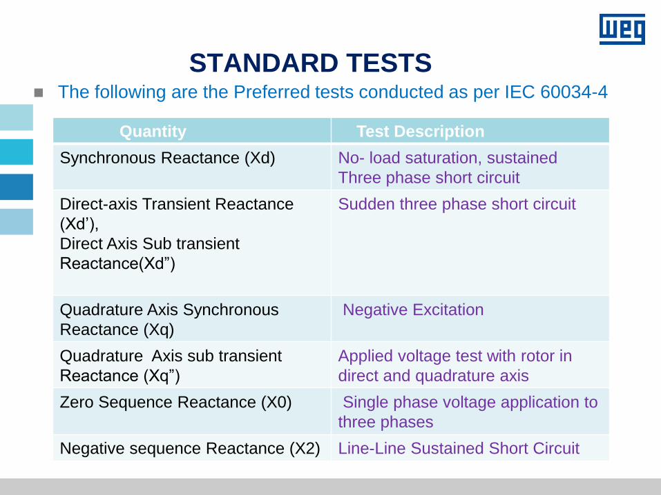
STANDARD TESTS The following are the Preferred tests conducted as per IEC 60034-4
Quantity Test Description
Synchronous Reactance (Xd) No- load saturation, sustained
Three phase short circuit
Direct-axis Transient Reactance
(Xd’),
Direct Axis Sub transient
Reactance(Xd”)
Sudden three phase short circuit
Quadrature Axis Synchronous
Reactance (Xq)
Negative Excitation
Quadrature Axis sub transient
Reactance (Xq”)
Applied voltage test with rotor in
direct and quadrature axis
Zero Sequence Reactance (X0) Single phase voltage application to
three phases
Negative sequence Reactance (X2) Line-Line Sustained Short Circuit
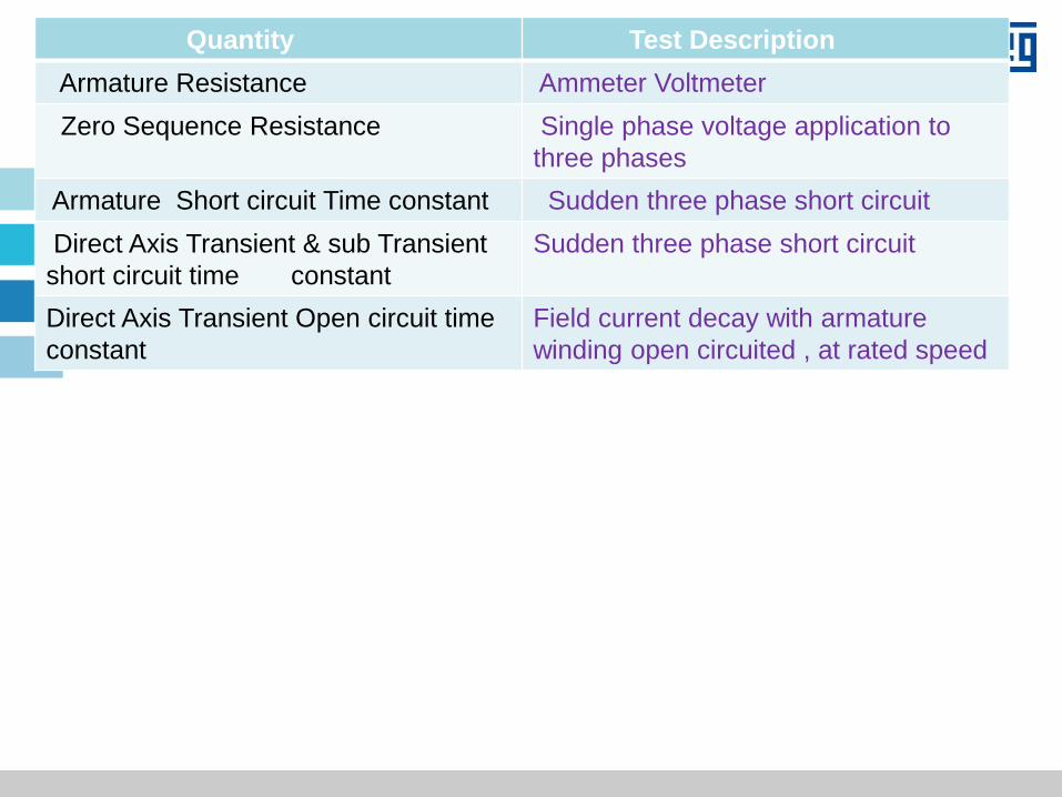
Quantity Test Description
Armature Resistance Ammeter Voltmeter
Zero Sequence Resistance Single phase voltage application to
three phases
Armature Short circuit Time constant Sudden three phase short circuit
Direct Axis Transient & sub Transient
short circuit time constant
Sudden three phase short circuit
Direct Axis Transient Open circuit time
constant
Field current decay with armature
winding open circuited , at rated speed
THANK YOU
101