Embed Size (px)
Citation preview
Week 2 Lecture 2
Structure of a database
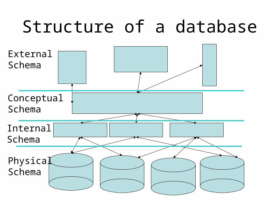
Structure of a database
ExternalSchema
ConceptualSchema
InternalSchema
PhysicalSchema
External level
• Level visible to user
• Multiple views of the system– e.g. View an order - see limited product and
customer information
• Only the database Administrator may access the whole database at this level
EXTERNAL SCHEMA
• Each external view is defined by means of an external schema
• Provides definitions of each external view.• Written in a Data Definition Language• individual to the user • accessed through a 3GL, a query language or a
special purpose forms or menu-based language
Conceptual level
• CONCEPTUAL - represents the entire information content of the database
• Consists of multiple types of conceptual record. This level preserves the data independence of the database.
• CONCEPTUAL SCHEMA - defines each of the various types of conceptual record, in a conceptual Data Definition Language.
Internal level
• INTERNAL - a low-level representation of the entire database; it consists of multiple occurrences of multiple types of internal record. It is the stored record, inasmuch as it contains all but the device-specific information on the storage of the database.
• PHYSICAL - the physical device and block addresses for each of the records.
Mappings
• Each level maps onto adjoining levels• conceptual / internal mapping specifies how
conceptual records and fields are represented at the internal level
• Changes can be made in the internal level without affecting the conceptual level
• external / conceptual mapping defines the correspondence between an external view and the conceptual view
DBMS - Database Management System
• software handling access to the database
• allows both the database administrator and all users the access to the database to which they are entitled
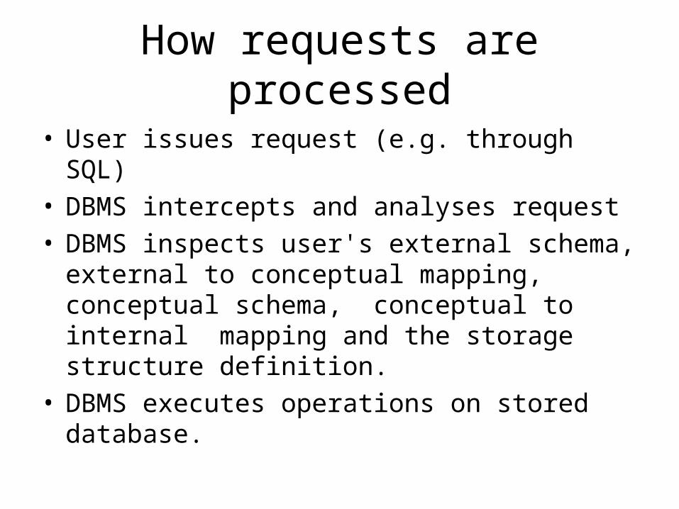
How requests are processed
• User issues request (e.g. through SQL)• DBMS intercepts and analyses request• DBMS inspects user's external schema, external
to conceptual mapping, conceptual schema, conceptual to internal mapping and the storage structure definition.
• DBMS executes operations on stored database.
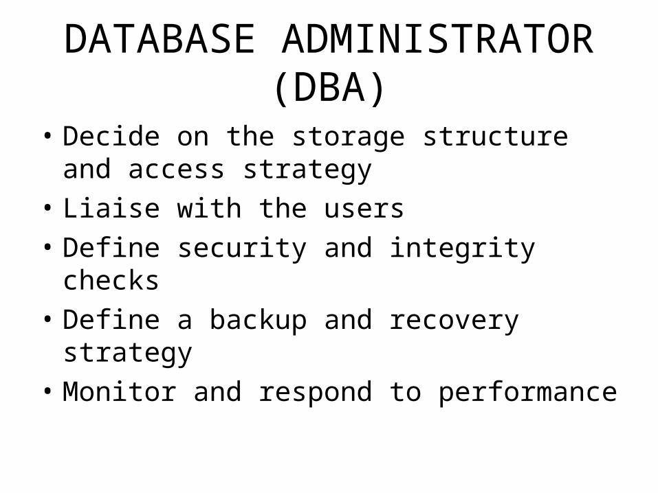
DATABASE ADMINISTRATOR (DBA)
• Decide on the storage structure and access strategy
• Liaise with the users
• Define security and integrity checks
• Define a backup and recovery strategy
• Monitor and respond to performance
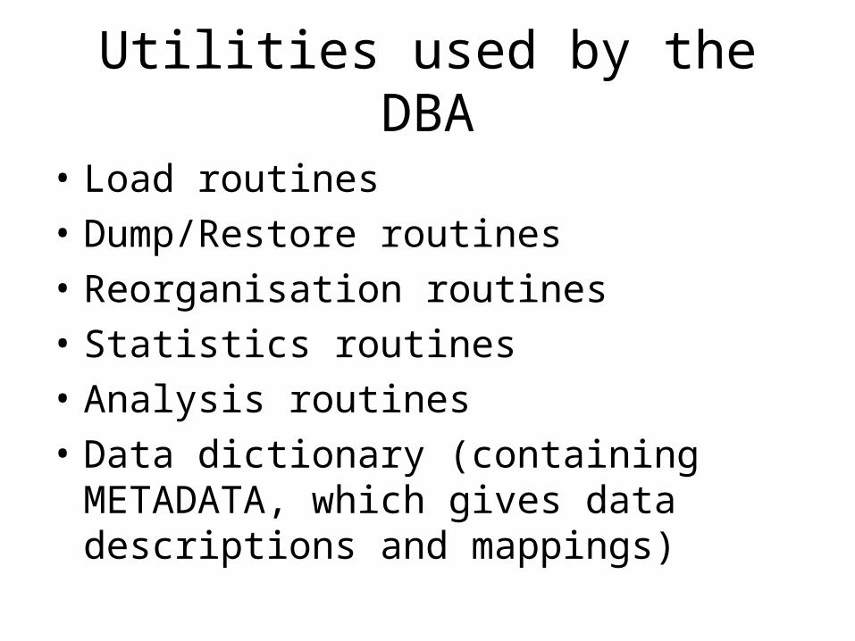
Utilities used by the DBA
• Load routines
• Dump/Restore routines
• Reorganisation routines
• Statistics routines
• Analysis routines
• Data dictionary (containing METADATA, which gives data descriptions and mappings)
Building a conceptual schema
Please note: The diagrams in this presentation are drawn using a tool
that you will not be using. You will be using ERWin.
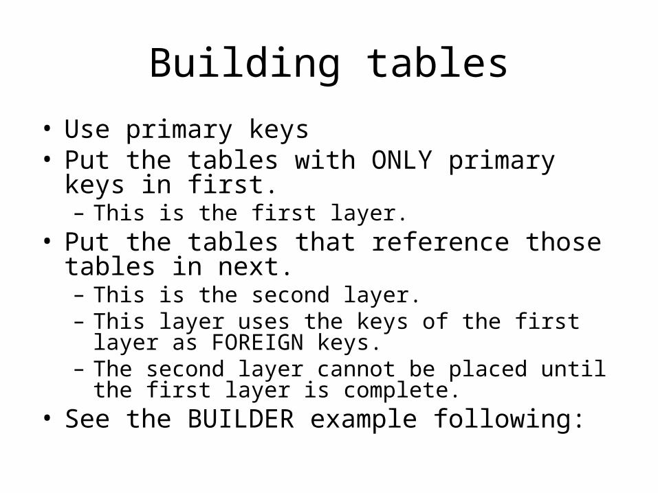
Building tables
• Use primary keys• Put the tables with ONLY primary keys in first.
– This is the first layer.• Put the tables that reference those tables in
next. – This is the second layer.– This layer uses the keys of the first layer as
FOREIGN keys.– The second layer cannot be placed until the first layer
is complete.• See the BUILDER example following:
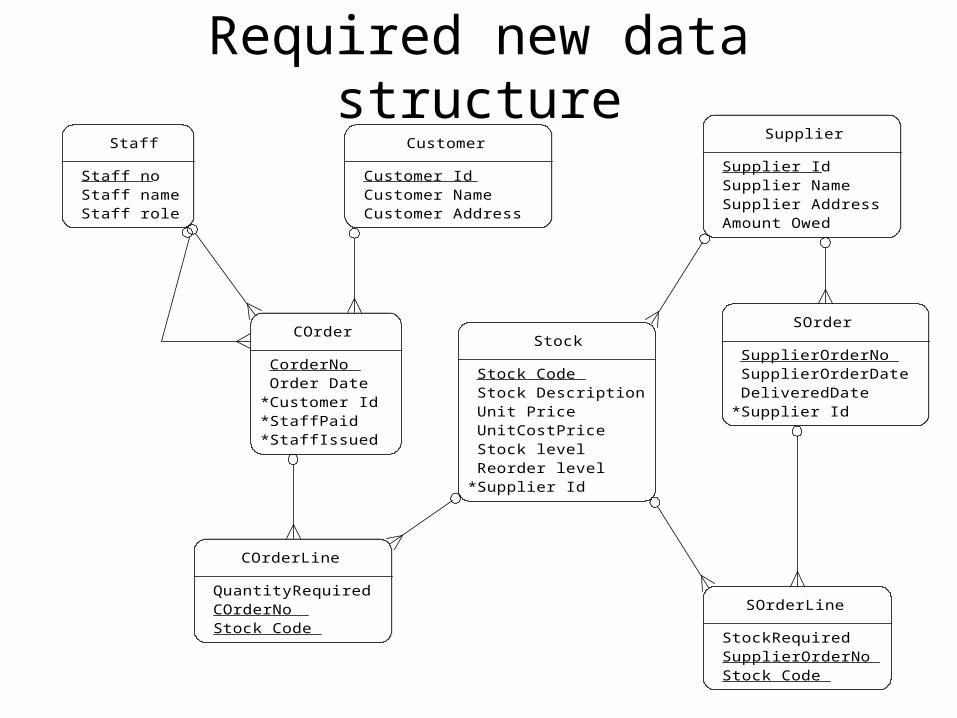
Required new data structure
COrder
CorderNoOrder Date
* Customer Id* StaffPaid* StaffIssued
COrderLine
QuantityRequiredCOrderNoStock Code
Customer
Customer IdCustomer NameCustomer Address
SOrder
SupplierOrderNoSupplierOrderDateDeliveredDate
* Supplier Id
SOrderLine
StockRequiredSupplierOrderNoStock Code
Staff
Staff noStaff nameStaff role
Stock
Stock CodeStock DescriptionUnit PriceUnitCostPriceStock levelReorder level
* Supplier Id
Supplier
Supplier IdSupplier NameSupplier AddressAmount Owed
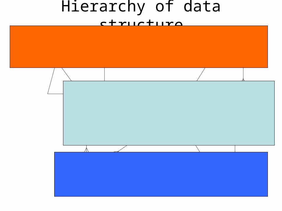
Hierarchy of data structure
Please note
• To show self-joins, the staff table has since been amended:alter table staff add reports_to number(7);
alter table staff add constraint has_as_boss foreign key (reports_to) references staff(staff_no);
• The new structure is the same as the one in the ‘builder schema’ link in your web page and webCT.
Layers of tables
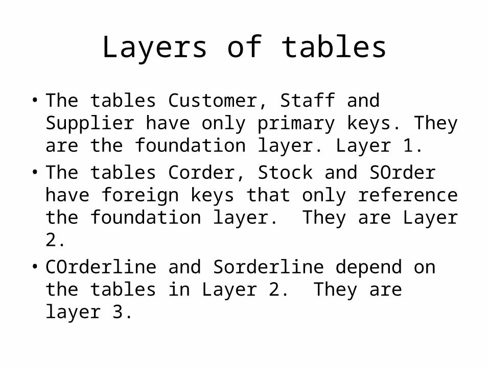
• The tables Customer, Staff and Supplier have only primary keys. They are the foundation layer. Layer 1.
• The tables Corder, Stock and SOrder have foreign keys that only reference the foundation layer. They are Layer 2.
• COrderline and Sorderline depend on the tables in Layer 2. They are layer 3.

Analogous to building bricks
Layer 1
Cus
tom
erC
usto
mer
Sta
ffS
taff
Supp
lier
Supp
lier
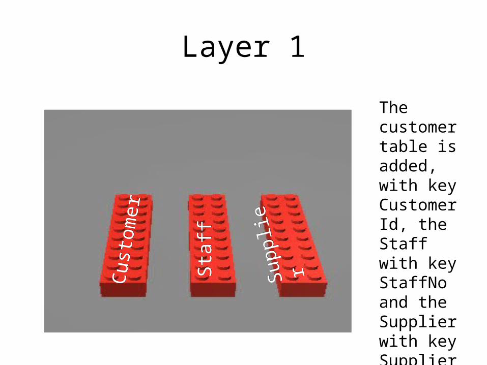
The customer table is added, with key CustomerId, the Staff with key StaffNo and the Supplier with key SupplierId.
Layer 2
COrder
Stock
SOrder
CustomerStaffSupplier
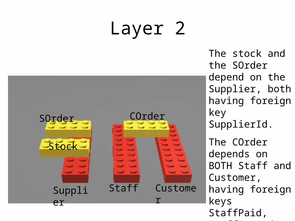
The stock and the SOrder depend on the Supplier, both having foreign key SupplierId.
The COrder depends on BOTH Staff and Customer, having foreign keys StaffPaid, StaffIssued and CustomerId.
Layer 3
Supplier Staff Customer
COrderStock
SOrder
SOrderlineSOrderline COrderlineCOrderline
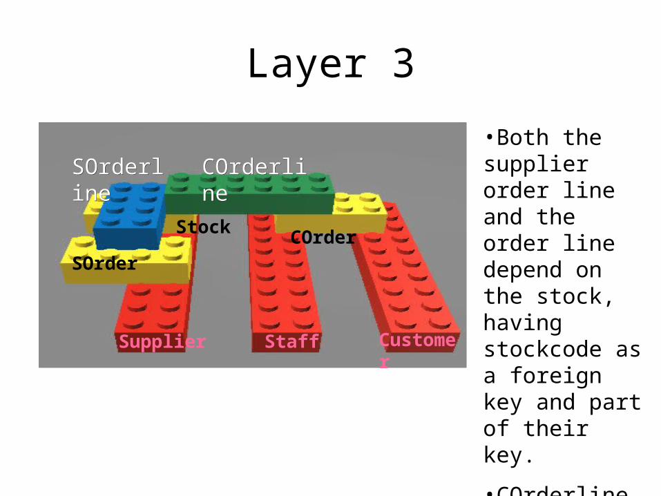
•Both the supplier order line and the order line depend on the stock, having stockcode as a foreign key and part of their key.
•COrderline depends on COrder.
•Sorderline depends on SOrder
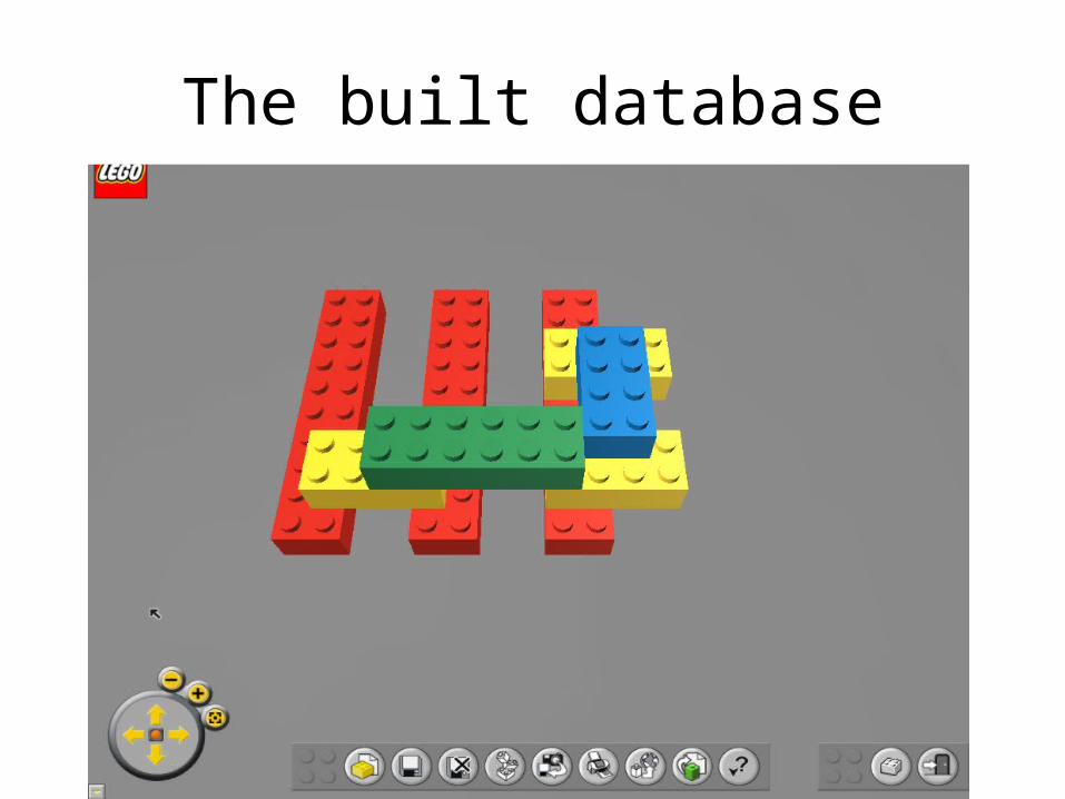
The built database
Recap
• Look back at the blocks.– The table creates are the structure or the framework
- i.e. the architect’s drawing– The inserts are like the bricks. You cannot insert
into a table unless there is supporting data in the table on which it depends.
• Do– Creates starting with the one(s) with no dependents– Inserts starting with the one(s) with no dependents– Deletes starting with the one(s) on which no other
depends– Drops starting with the one(s) on which no other
depends
Relational database design
• The conceptual schema is built using CREATE TABLE commands.
• A relation is relational…If and only if every non-key attribute is determined by the KEY… the WHOLE KEY…. and nothing but the KEY so help me CODD!Dr. E.F. Codd, an IBM researcher, first developed the
relational data model in 1970
Bottom-up Approach to Data Modelling
• Objectives– Define the purpose of normalisation– Determinacy / Dependency– Defining the Data Dictionary– First Normal Form– Second Normal Form– Third Normal Form
10
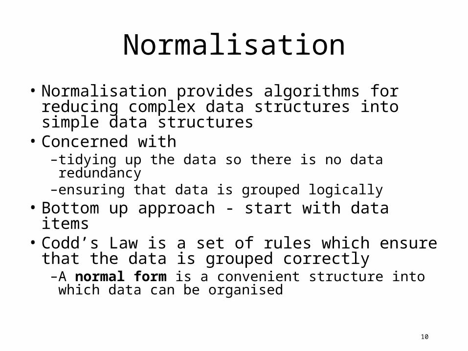
Normalisation
• Normalisation provides algorithms for reducing complex data structures into simple data structures
• Concerned with –tidying up the data so there is no data redundancy–ensuring that data is grouped logically
• Bottom up approach - start with data items• Codd’s Law is a set of rules which ensure that
the data is grouped correctly–A normal form is a convenient structure into which
data can be organised
Concept of Determinacy and Dependency
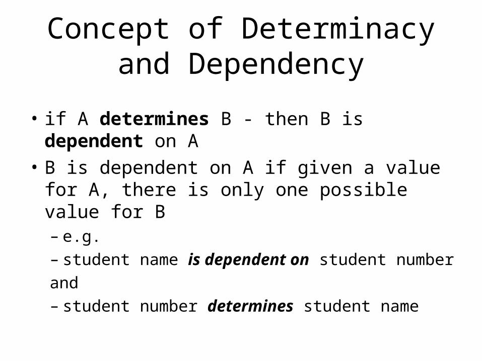
• if A determines B - then B is dependent on A
• B is dependent on A if given a value for A, there is only one possible value for B– e.g. – student name is dependent on student number
and– student number determines student name
Data Dictionary
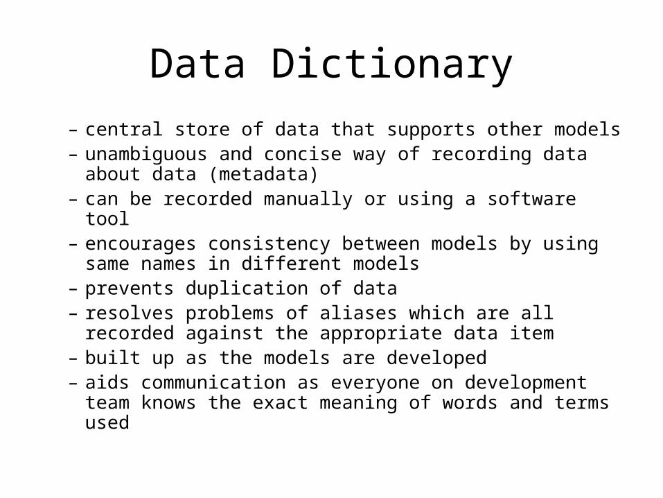
– central store of data that supports other models– unambiguous and concise way of recording data about
data (metadata)– can be recorded manually or using a software tool– encourages consistency between models by using
same names in different models– prevents duplication of data– resolves problems of aliases which are all recorded
against the appropriate data item– built up as the models are developed– aids communication as everyone on development team
knows the exact meaning of words and terms used
Sequence, selection, iteration
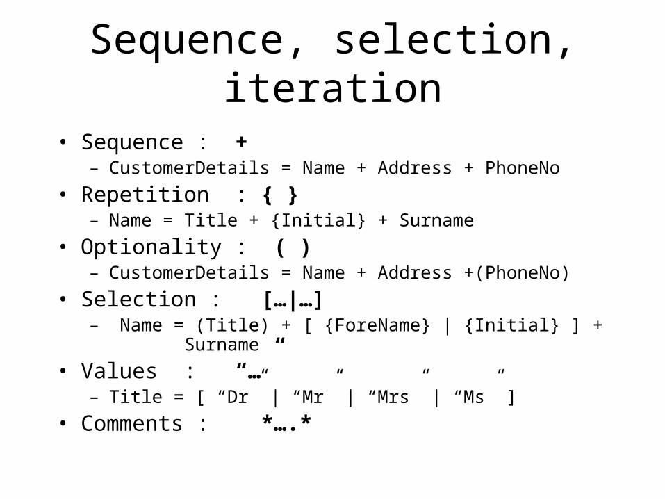
• Sequence : +– CustomerDetails = Name + Address + PhoneNo
• Repetition : { }– Name = Title + {Initial} + Surname
• Optionality : ( )– CustomerDetails = Name + Address +(PhoneNo)
• Selection : […|…]– Name = (Title) + [ {ForeName} | {Initial} ] +
Surname
• Values : “…”– Title = [ “Dr” | “Mr” | “Mrs” | “Ms” ]
• Comments : *….*
4
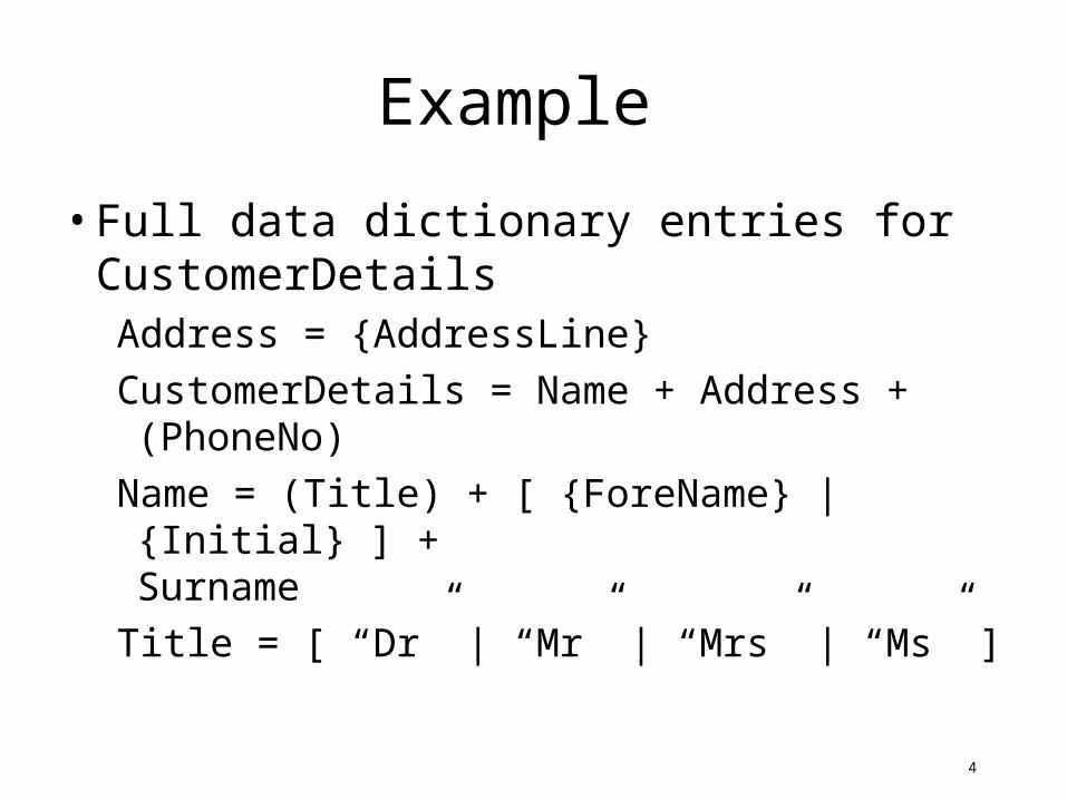
Example
• Full data dictionary entries for CustomerDetailsAddress = {AddressLine}
CustomerDetails = Name + Address + (PhoneNo)
Name = (Title) + [ {ForeName} | {Initial} ] +Surname
Title = [ “Dr” | “Mr” | “Mrs” | “Ms” ]
Two Technique Approach to Data Modelling
• E-R diagramming to find and group all data items
• normalisation to ensure data items are grouped correctly
Before we begin…
• We have already discussed– Entities– Attributes– Values– Data and Metadata
• We now take one of the documents and apply:– Unnormalised form rules (Data Dictionary format)– First Normal Form rules– Second Normal Form rules– Third Normal Form rules
![[MC-CSDL-Diff]: Conceptual Schema Definition File Format€¦ · 8 / 127 [MC-CSDL-Diff] - v20190313 Conceptual Schema Definition File Format Copyright © 2019 Microsoft Corporation](https://img.pdfslide.us/doc/110x75/603fb4fb83421b450c41884d/mc-csdl-diff-conceptual-schema-definition-file-format-8-127-mc-csdl-diff.jpg)


![[MS-CSDLBI]: Conceptual Schema Definition File …...The conceptual schema definition file format with business intelligence (BI) annotations provides the structure and semantics of](https://img.pdfslide.us/doc/110x75/5f07e25d7e708231d41f3cb7/ms-csdlbi-conceptual-schema-definition-file-the-conceptual-schema-definition.jpg)


![[MS-CSDLBI]: Conceptual Schema Definition File Format with ... · The conceptual schema definition file format with business intelligence (BI) annotations provides the structure and](https://img.pdfslide.us/doc/110x75/5f10087d7e708231d4471c94/ms-csdlbi-conceptual-schema-definition-file-format-with-the-conceptual-schema.jpg)


![[MS-CSDLBI-Diff]: Conceptual Schema Definition File Format ...download.microsoft.com/download/C/2/E/C2E4BF6C-8F... · The conceptual schema definition file format with business intelligence](https://img.pdfslide.us/doc/110x75/5d263b4a88c993bb408bd3d3/ms-csdlbi-diff-conceptual-schema-definition-file-format-the-conceptual.jpg)
![[MC-CSDL]: Conceptual Schema Definition File Format · 8 / 141 [MC-CSDL] — v20130722 Conceptual Schema Definition File Format Copyright © 2013 Microsoft Corporation. Release: Monday,](https://img.pdfslide.us/doc/110x75/5e71b48b783af846701a85f7/mc-csdl-conceptual-schema-definition-file-format-8-141-mc-csdl-a-v20130722.jpg)


![[MC-CSDL]: Conceptual Schema Definition File FormatMC-CSDL]-140515.… · [MC-CSDL]: Conceptual Schema Definition File Format Intellectual Property Rights Notice for Open Specifications](https://img.pdfslide.us/doc/110x75/5f610a51a891c260525fe103/mc-csdl-conceptual-schema-definition-file-format-mc-csdl-140515-mc-csdl.jpg)
![[MS-CSDLBI]: Conceptual Schema Definition File Format with ...download.microsoft.com/download/1/7/5/175A7833-6F75-418D-8800-86D44D1D... · Conceptual Schema Definition File Format](https://img.pdfslide.us/doc/110x75/5d263ba888c993bb408bd4b9/ms-csdlbi-conceptual-schema-definition-file-format-with-conceptual-schema.jpg)
![[MC-CSDL]: Conceptual Schema Definition File Format...8 / 127 [MC-CSDL] - v20150630 Conceptual Schema Definition File Format Copyright © 2015 Microsoft Corporation Release: June 30,](https://img.pdfslide.us/doc/110x75/60b27250ecf53719904dbac7/mc-csdl-conceptual-schema-definition-file-format-8-127-mc-csdl-v20150630.jpg)


![[MS-CSDLBI]: Conceptual Schema Definition File Format with](https://img.pdfslide.us/doc/110x75/6156ff57a097e25c764fe369/ms-csdlbi-conceptual-schema-definition-file-format-with-.jpg)
