Embed Size (px)
Citation preview
WECC, Remedial Action Scheme Reliability Subcommittee
Information Required to Assess the Reliability of a RAS
Procedure to Submit a RAS for Assessment
Revised August 2012
El Nido & El Segundo Centralized RAS (CRAS) Modification
(Operating Date: Oct. 8, 2018)
Southern California Edison Company
Sept 28, 2018
Phillip Leung
Ben Coalson
Pramod Korti
Bill Zhang
Procedure to Submit a RAS for Assessment Page 2/32
RAS Name: NidoSegundo RAS Owner: Southern California Edison Company Revision No: V02.00 Submittal Date: 09/28/2018
Information Required to Assess the Reliability of a RAS PAGE
Contents
WECC RAS INITIAL OR PERIODIC ASSESSMENT SUMMARY ........................... 3
A. RAS PURPOSE AND OVERVIEW ................................................................ 3
B. RAS DESIGN ............................................................................................... 12
C. MONITORING .............................................................................................. 24
D. RAS OPERATING PROCEDURES FOR ABNORMAL SYSTEM CONDITIONS............................................................................................... 25
E. COMMISSIONING, MAINTENANCE AND TESTING .................................. 27
F. PERFORMANCE AND OPERATIONAL HISTORY ..................................... 30
Attachment A WECC RAS Initial or Periodic Assessment Summary ................... 31
Attachment B WECC RAS Database ................................................................... 32
Procedure to Submit a RAS for Assessment Page 3/32
RAS Name: NidoSegundo RAS Owner: Southern California Edison Company Revision No: V02.00 Submittal Date: 09/28/2018
WECC RAS INITIAL OR PERIODIC ASSESSMENT SUMMARY
For all new or modified RAS, also provide information required by the WECC RAS Initial or Periodic Assessment Summary, as maintained by the RASRS. See Attachment A WECC RAS Initial or Periodic Assessment Summary Provide the name and contact information of the person responsible for this RAS data submittal. Bill Zhang 909-274-1505 [email protected]
If a classification of LAPS is claimed by the Reporting Party, full scheme review by the RASRS is generally not required unless this classification is not agreed to by the RASRS. The Reporting party must provide adequate information for the RASRS to judge the proposed scheme classification. If a full RASRS scheme review is not required (LAPS), the RAS owner is still responsible for meeting all of the requirements of the RAS Criterion. If a full RASRS review is required (for WAPS or SN, the following information, Sections A - F must be submitted for review:
A. RAS PURPOSE AND OVERVIEW
1) Identify the ownership of the RAS (the Reporting Party).
Southern California Edison Company
2) Provide the name of the RAS, the purpose and the desired in-service date. Include the
specific type of system problem(s) being solved, e.g. transient stability, thermal overload, voltage stability, etc.
a. Name: CRAS (NidoSegundo RAS)
b. Purpose: CRAS (NidoSegundo Analytic) will deploy a centralized, expandable RAS controller that initially integrates the analytic functions of the existing El Nido and El Segundo RAS systems (to be removed). The purpose of the El Nido RAS Analytic is to mitigate thermal overload problems related to double contingencies of the following 220 kV transmission lines:
• El Nido – La Fresa No. 3 220 kV T/L
• El Nido – La Fresa No. 4 220 kV T/L
• La Cienega – La Fresa 220 kV T/L
Procedure to Submit a RAS for Assessment Page 4/32
RAS Name: NidoSegundo RAS Owner: Southern California Edison Company Revision No: V02.00 Submittal Date: 09/28/2018
A potential thermal overload problem in the La Fresa Sub-Area was identified through the 2009 California Independent System Operator (CAISO) Local Capacity Requirement study. Under the loss of any two out of the three lines in the La Fresa-El Nido-La Cienega area, the remaining line is inadequate to support the load at El Nido, La Cienega, and Chevmain substations, resulting in a thermal overload of the remaining line. The purpose of the El Segundo RAS Analytic is to mitigate for a severe thermal overload (exceeds the Emergency Rating) of the El Nido – La Cienega 220 kV line following the N-2 loss of the El Nido – La Fresa No. 3 and No. 4 220 kV lines. Once this N-2 contingency occurs and thermal overload occurs on the El Nido – La Cienega 220 line, then pre-selected El Segundo Units 5 – 8 are tripped to relieve the thermal overload. There is no transient stability problem associated with this RAS scheme. Generation tripping is implemented following a 2-second delay. A 2-second delay is being implemented in case 220 kV line reclosing is implemented in the transmission corridor West of La Fresa substation.
3) Provide the owner’s classification of the RAS as a LAPS, WAPS, or SN.
The El Nido analytic is a WAPS, since more than 300 MW of load is at risk. The El Segundo analytic is a LAPS, since less than 1000 MW of generation is at risk. The combined El Nido/El Segundo CRAS analytic is therefore classified as a WAPS.
4) Provide the information required to populate the WECC RAS database using the
appropriate Excel spreadsheet, PRC-013 template (available on the WECC web site). The specific data required is also listed in Attachment A. See attached extract from WECC RAS Database.
5) Provide the name(s) of person(s) within the owner’s organization who is (are) responsible
for the operation and maintenance of the RAS.
Operational Contact: Timothy Kedis Principal Manager, Grid Control Center Phone: (909) 274-3360
Maintenance Contact: Jim Cherrie Director of Substation Construction and Maintenance Phone: (909) 274-3597
6) Provide a description of the RAS to give an overall understanding of the functionality and
a map showing the location of the RAS. Identify other protection and control systems requiring coordination with the RAS. See “RAS Design”, below, for additional information.
CRAS (NidoSegundo Analytic) is the initial deployment of a centralized, expandable RAS controller that initially integrates the analytic functions of the existing El Nido and El Segundo RAS systems. Together, these analytic functions constitute a contingency-based load and generation tripping scheme featuring completely redundant and diversely routed communications facilities and automatic arming functions.
Procedure to Submit a RAS for Assessment Page 5/32
RAS Name: NidoSegundo RAS Owner: Southern California Edison Company Revision No: V02.00 Submittal Date: 09/28/2018
The CRAS Central Controllers at GCC and AGCC perform the central logic processing function which consists of arming calculation, contingency recognition, and transmission of required load tripping signals. The El Nido portion of the El Nido/El Segundo Analytic monitors the following three 220 kV lines:
• El Nido – La Fresa No. 3 220 kV T/L
• El Nido – La Fresa No. 4 220 kV T/L
• La Cienega – La Fresa 220 kV T/L
When armed, CRAS is designed to drop load to mitigate a thermal overload condition that could occur on the remaining line should any two of the monitored lines (N-2) be removed from service. Note: This equates to three N-2 contingencies. The NidoSegundo Analytic continually receives pre-contingency line loadings (above) and the loading values of three separate load groups (below) from the Line Monitor and Mitigation N60 relays, via the low-priority GOOSE stream, to determine the appropriate amount of load to drop for each of the three identified N-2 outage contingencies. The existing analytic then automatically arms/disarms the following load groups as required. •El Nido Sub No.5 & No.6 66/16 kV Banks (up to 84 MW). •Felton, Inglewood, and Lennox Substations 66/16 kV Banks (up to 200 MW). •La Cienega Sub 3A & 4A Banks (up to 521 MW). This request proposes to modify the analytic to remove the second of the three load groups above to provide additional reliability of service to new load being looped into the subtransmission lines linking Felton, Inglewood, and Lennox Substations. System studies have shown that tripping the El Nido Sub No.5 & No.6 66/16 kV banks and the La Cienega Sub 3A and 4A banks is sufficient to mitigate any adverse system conditions that would occur. The following are the two remaining load groups after the proposed modification: • El Nido Sub No.5 & No.6 66/16 kV Banks (up to 84 MW). • La Cienega Sub 3A & 4A Banks (up to 521 MW). GE N60 relays are used to monitor line outage status at El Nido, La Cienega and La Fresa substations. Additional N60 relays are used at El Nido and La Cienega Substations for load tripping. Wide area GOOSE communication is used between relays and Central Controllers. Direct I/O is used between CRAS A and B relays for CB disagreement detection.
Procedure to Submit a RAS for Assessment Page 6/32
RAS Name: NidoSegundo RAS Owner: Southern California Edison Company Revision No: V02.00 Submittal Date: 09/28/2018
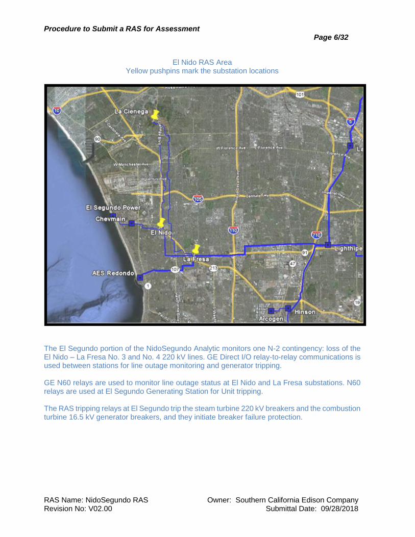
El Nido RAS Area
Yellow pushpins mark the substation locations
The El Segundo portion of the NidoSegundo Analytic monitors one N-2 contingency: loss of the El Nido – La Fresa No. 3 and No. 4 220 kV lines. GE Direct I/O relay-to-relay communications is used between stations for line outage monitoring and generator tripping. GE N60 relays are used to monitor line outage status at El Nido and La Fresa substations. N60 relays are used at El Segundo Generating Station for Unit tripping. The RAS tripping relays at El Segundo trip the steam turbine 220 kV breakers and the combustion turbine 16.5 kV generator breakers, and they initiate breaker failure protection.
Procedure to Submit a RAS for Assessment Page 7/32
RAS Name: NidoSegundo RAS Owner: Southern California Edison Company Revision No: V02.00 Submittal Date: 09/28/2018
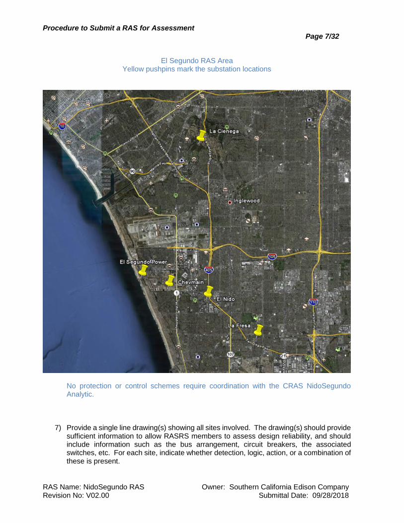
El Segundo RAS Area
Yellow pushpins mark the substation locations
No protection or control schemes require coordination with the CRAS NidoSegundo Analytic.
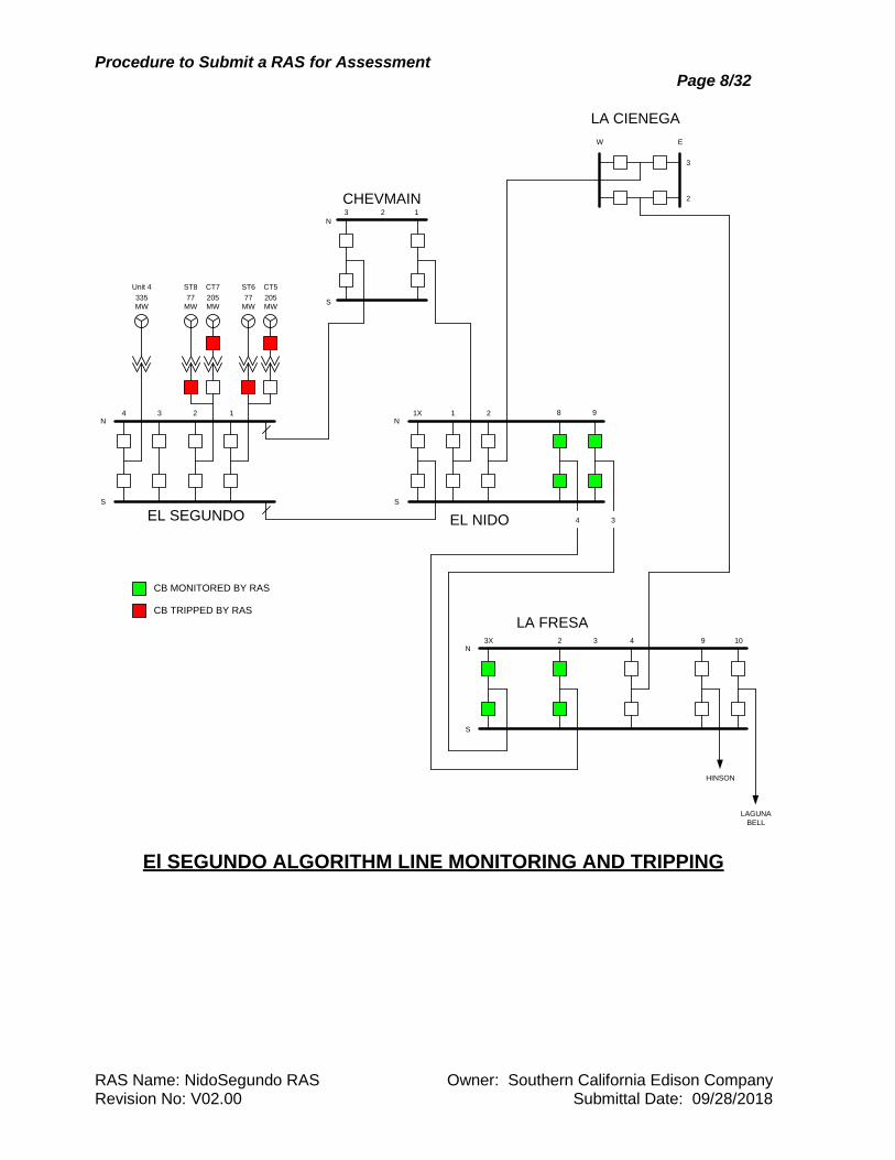
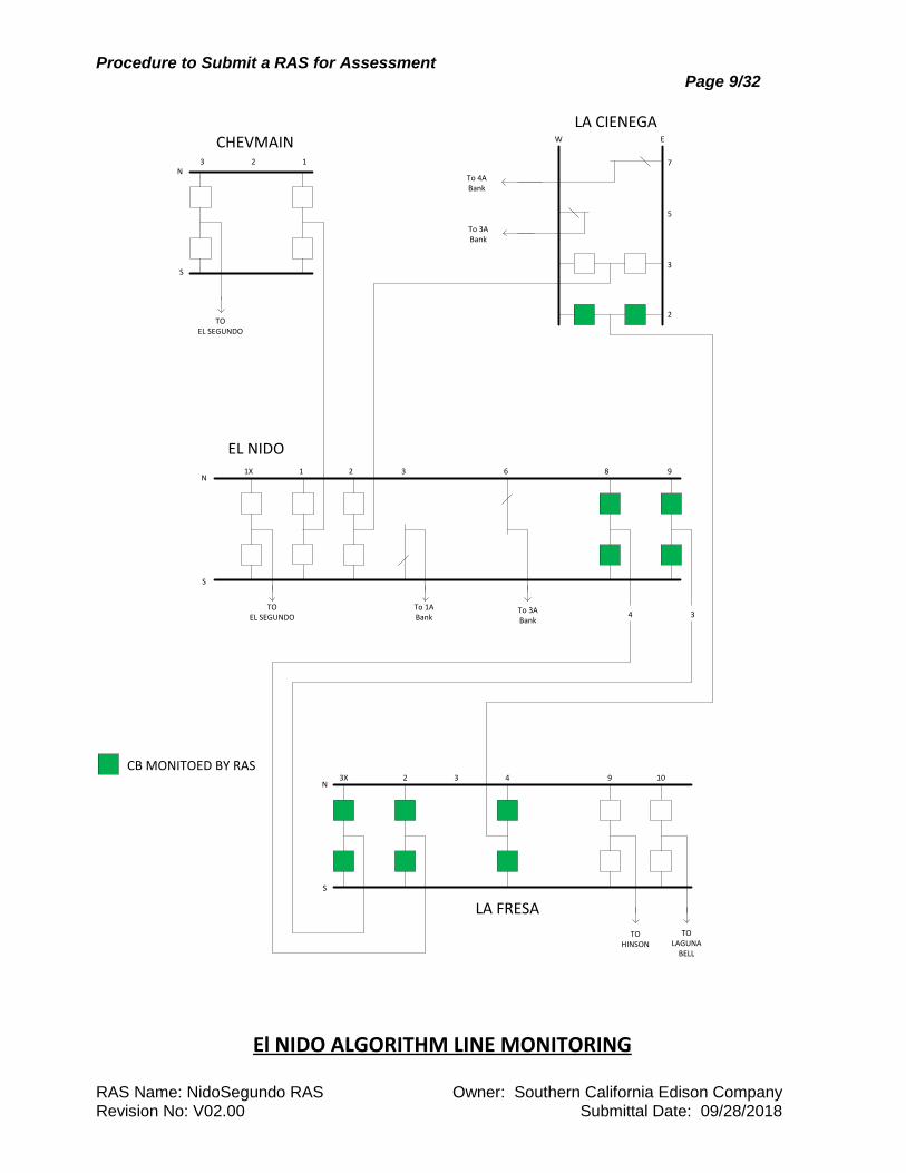
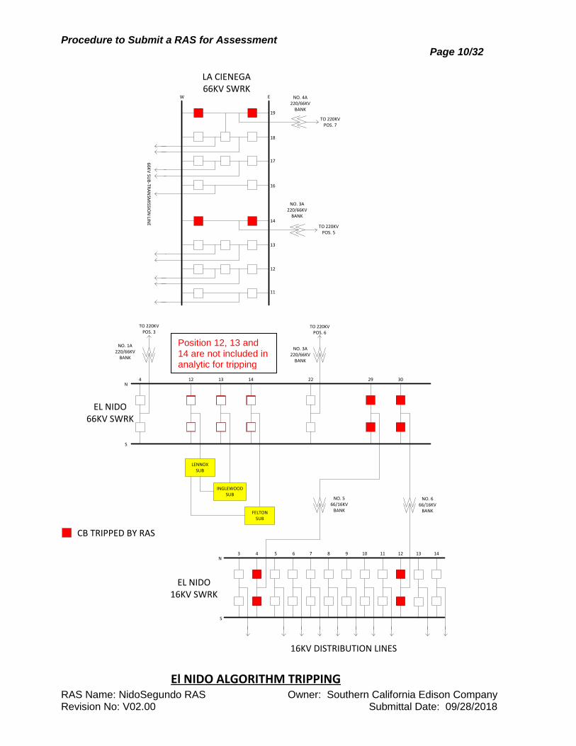
7) Provide a single line drawing(s) showing all sites involved. The drawing(s) should provide sufficient information to allow RASRS members to assess design reliability, and should include information such as the bus arrangement, circuit breakers, the associated switches, etc. For each site, indicate whether detection, logic, action, or a combination of these is present.
Procedure to Submit a RAS for Assessment Page 8/32
RAS Name: NidoSegundo RAS Owner: Southern California Edison Company Revision No: V02.00 Submittal Date: 09/28/2018
4 3 2 1N
S
EL SEGUNDO
CT5
205
MW
CB MONITORED BY RAS
CB TRIPPED BY RAS
ST6
77
MW
Unit 4
335
MW
CT7
205
MW
ST8
77
MW
1X 1 2 8N
S
EL NIDO
3 2
N
S
CHEVMAIN1
3X 2 3 4N
S
LA FRESA
3
2
EW
9
LA CIENEGA
4 3
9 10
HINSON
LAGUNA
BELL
El SEGUNDO ALGORITHM LINE MONITORING AND TRIPPING
Procedure to Submit a RAS for Assessment Page 9/32
RAS Name: NidoSegundo RAS Owner: Southern California Edison Company Revision No: V02.00 Submittal Date: 09/28/2018
LA FRESA
942N
S
10
CHEVMAIN123
N
S
TO EL SEGUNDO
7
5
3
2
LA CIENEGA
EL NIDO
W E
CB MONITOED BY RAS
6N
S
83211X
To 1ABank
To 3ABank
TOEL SEGUNDO
To 4ABank
To 3ABank
4 3
9
3X 3
TOHINSON
TOLAGUNA
BELL
El NIDO ALGORITHM LINE MONITORING
Procedure to Submit a RAS for Assessment Page 10/32
RAS Name: NidoSegundo RAS Owner: Southern California Edison Company Revision No: V02.00 Submittal Date: 09/28/2018
14N
S
2213124 29 30
INGLEWOODSUB
LENNOXSUB
FELTONSUB
NO. 3A 220/66KV
BANK
TO 220KVPOS. 6
NO. 1A 220/66KV
BANK
TO 220KVPOS. 3
EL NIDO66KV SWRK
CB TRIPPED BY RAS
16KV DISTRIBUTION LINES
6N
S
7543 8 9
EL NIDO16KV SWRK
10 11 12 13 14
NO. 6 66/16KV
BANK
NO. 5 66/16KV
BANK
16
EW
13
17
18
19
NO. 3A 220/66KV
BANK
TO 220KVPOS. 5
NO. 4A 220/66KV
BANK
TO 220KVPOS. 7
LA CIENEGA66KV SWRK
14
12
11
66
KV
SUB
-TRA
NSM
ISSION
LINE
El NIDO ALGORITHM TRIPPING
Position 12, 13 and 14 are not included in analytic for tripping
Procedure to Submit a RAS for Assessment Page 11/32
RAS Name: NidoSegundo RAS Owner: Southern California Edison Company Revision No: V02.00 Submittal Date: 09/28/2018
8) Indicate the type of system reliability studies performed and a list of any that are in progress. In the Resources Adequacy Local Capacity Requirement proceeding, the California Independent System Operator (CAISO) identified a potential thermal violation when local generation (mainly El Segundo and Chevron generating units) is running low or near zero output. The study results are posted in the annual CAISO’s Local Capacity Technical Analysis report. SCE also performed a similar study that included stability and thermal assessment. Results from both studies did not indicate any dynamic or cascading issues. Thermal overload problems were limited to transmission facilities in the nearby area. It was concluded that the violation and mitigation associated with this RAS has no impact on the remaining WECC transmission grid. The purpose of the El Nido Analytic component of CRAS is to mitigate the potential thermal overloads on the La Cienega – La Fresa and El Nido – La Fresa 220kV lines. These thermal violations do not cascade or have other adverse impacts to the electric grid. For the Technical Assessment that identified the need for the El Segundo RAS, a power flow case was prepared that looked at a wide range of load levels, generation levels and voltage conditions unlike the System Impact Study, which looks at only two system conditions (Heavy Summer and Light Spring). Through this type of analysis, the RAS Arming Study identified the appropriate double contingency that needs to be protected by the RAS.
9) Provide a discussion of the impact to the WECC power grid, including other protection
and control systems that result from the actions taken by the proposed RAS and from its failure to operate as expected. Does a failure to operate or a misoperation impact an Intertie Path? If yes, what Intertie Path? If the El Nido Analytic component of CRAS fails to operate as designed, the result would be thermal overload of one of the following three lines, depending on the initiating contingency: El Nido – La Fresa No. 3, El Nido – La Fresa No. 4 or La Cienega – La Fresa 220 kV line. If the El Segundo Analytic component of CRAS fails to operate as designed, the result would be thermal overload of the El Nido – La Cienega 220 kV line. The implementation of the CRAS (NidoSegundo Analytic) effectively makes the existing El Nido and El Segundo legacy RAS systems obsolete. In conjunction to modifying the existing analytic, SCE proposes to decommission the legacy RASs and remove them from service. This will increase system reliability by eliminating the potential for unnecessary loss of generation or load due to misoperation of these redundant systems. No other adverse impacts on the WECC power grid were identified. Failure or misoperation of CRAS El Nido or El Segundo Analytics does not impact any intertie paths.
Procedure to Submit a RAS for Assessment Page 12/32
RAS Name: NidoSegundo RAS Owner: Southern California Edison Company Revision No: V02.00 Submittal Date: 09/28/2018
B. RAS DESIGN
1) Describe the design philosophy (e.g. failure is to be a non-credible event).
The RAS is designed to withstand a single failure without incurring a failure to transfer a legitimate trip command when required. The RAS has been designed as two completely separate identical RAS systems, designated as CRAS-A and CRAS-B, such that failure of a single component cannot prevent the scheme from operating. The scheme has been designed to be able to remove either system for test and continue to operate indefinitely on the redundant system. Separately protected, monitored, and annunciated DC supply circuits are provided for each RAS system. Each system has separate switches for maintenance and can be enabled or disabled separately. Independent relay hardware is used for line-loss detection and load tripping equipment. Arming is controlled automatically by the CRAS Central Controllers.
2) Describe the design criteria (e.g. failure of a single component, element or system
will not jeopardize the successful operation of the RAS).
The design criteria for the RAS require that failure of the RAS is to be a non-credible event. This is achieved by utilizing full equipment redundancy, with completely separate, identical systems known as CRAS-A and CRAS-B, so that failure of a single component, element, or system will not jeopardize the successful operation of the RAS. The CRAS Tripping relays initiate breaker failure protection when they operate, to guard against a stuck breaker that would otherwise prevent the required amount of load or generation to be tripped.
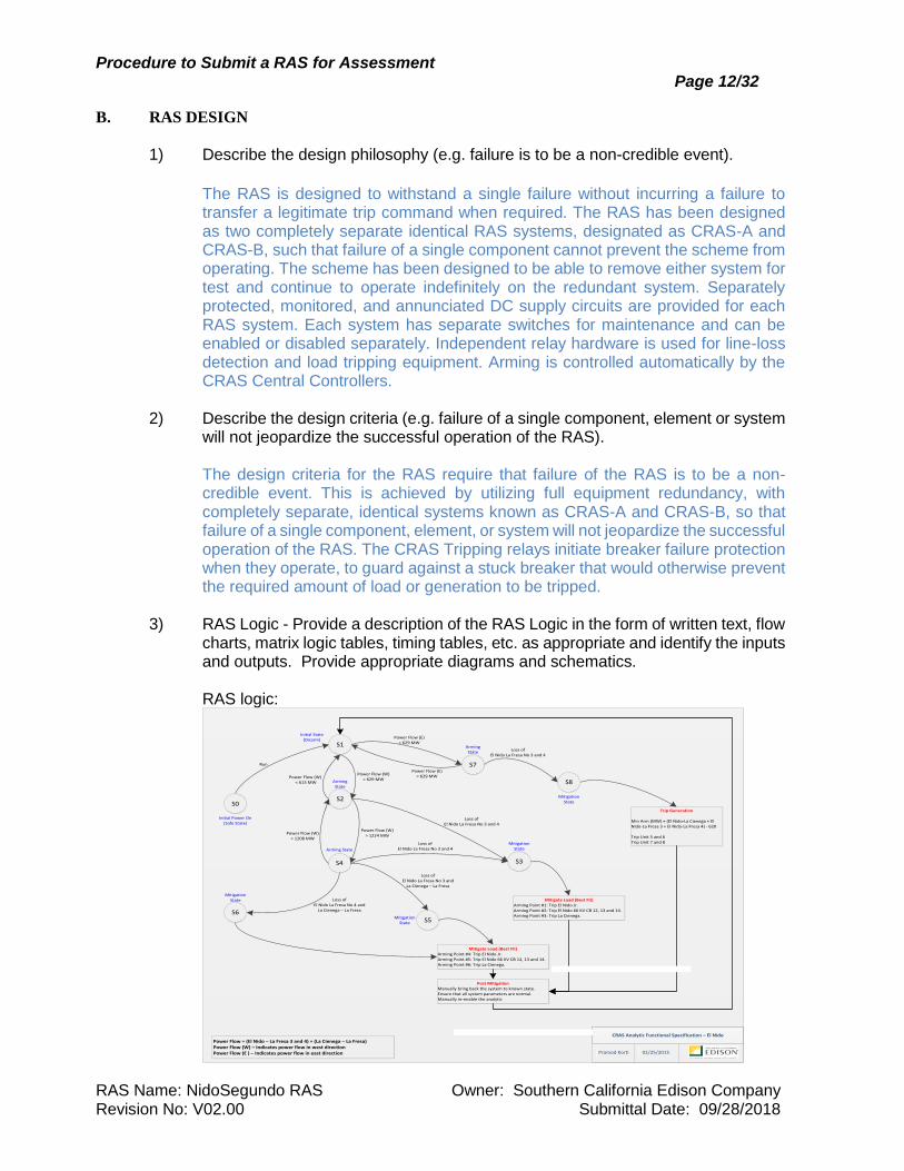
3) RAS Logic - Provide a description of the RAS Logic in the form of written text, flow
charts, matrix logic tables, timing tables, etc. as appropriate and identify the inputs and outputs. Provide appropriate diagrams and schematics.
RAS logic:
S0
S1
S2
Initial Power On(Safe State)
Run
Initial State(Disarm)
Power Flow (W) > 629 MWArming
State
Power Flow (W) < 613 MW
S3
Loss of El Nido La Fresa No 3 and 4
Mitigate Load (Best Fit)Arming Point #1: Trip El Nido Jr.Arming Point #2: Trip El Nido 66 KV CB 12, 13 and 14.Arming Point #3: Trip La Cienega.
Trip Generation
Min Arm (MW) = (El Nido‐La Cienega + El Nido‐La Fresa 3 + El Nido‐La Fresa 4) ‐ 620
Trip Unit 5 and 6Trip Unit 7 and 8
S4
Power Flow (W) > 1224 MW
Power Flow (W) < 1208 MW
S5
Loss of El Nido La Fresa No 3 and
La Cienega – La Fresa
Mitigate Load (Best Fit)Arming Point #4: Trip El Nido Jr.Arming Point #5: Trip El Nido 66 KV CB 12, 13 and 14.Arming Point #6: Trip La Cienega.
Arming State
Mitigation State
Mitigation State
S6
Loss of El Nido La Fresa No 4 and
La Cienega – La Fresa
Mitigation State
Post MitigationManually bring back the system to known state.Ensure that all system parameters are normal.Manually re-enable the analytic
Loss of El Nido La Fresa No 3 and 4
Loss of El Nido La Fresa No 3 and 4
Power Flow = (El Nido – La Fresa 3 and 4) + (La Cienega – La Fresa)Power Flow (W) – Indicates power flow in west directionPower Flow (E ) – Indicates power flow in east direction
S8
Mitigation State
S7
Power Flow (E) > 629 MW
Arming State
Power Flow (E) < 629 MW
CRAS Analytic Functional Specification – El Nido
Pramod Korti 02/25/2015
Procedure to Submit a RAS for Assessment Page 13/32
RAS Name: NidoSegundo RAS Owner: Southern California Edison Company Revision No: V02.00 Submittal Date: 09/28/2018
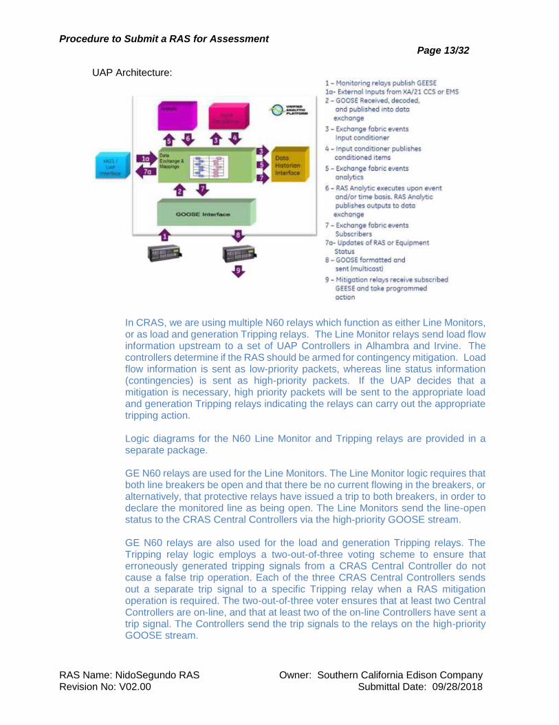
UAP Architecture:
In CRAS, we are using multiple N60 relays which function as either Line Monitors, or as load and generation Tripping relays. The Line Monitor relays send load flow information upstream to a set of UAP Controllers in Alhambra and Irvine. The controllers determine if the RAS should be armed for contingency mitigation. Load flow information is sent as low-priority packets, whereas line status information (contingencies) is sent as high-priority packets. If the UAP decides that a mitigation is necessary, high priority packets will be sent to the appropriate load and generation Tripping relays indicating the relays can carry out the appropriate tripping action.
Logic diagrams for the N60 Line Monitor and Tripping relays are provided in a
separate package.
GE N60 relays are used for the Line Monitors. The Line Monitor logic requires that both line breakers be open and that there be no current flowing in the breakers, or alternatively, that protective relays have issued a trip to both breakers, in order to declare the monitored line as being open. The Line Monitors send the line-open status to the CRAS Central Controllers via the high-priority GOOSE stream. GE N60 relays are also used for the load and generation Tripping relays. The Tripping relay logic employs a two-out-of-three voting scheme to ensure that erroneously generated tripping signals from a CRAS Central Controller do not cause a false trip operation. Each of the three CRAS Central Controllers sends out a separate trip signal to a specific Tripping relay when a RAS mitigation operation is required. The two-out-of-three voter ensures that at least two Central Controllers are on-line, and that at least two of the on-line Controllers have sent a trip signal. The Controllers send the trip signals to the relays on the high-priority GOOSE stream.
Procedure to Submit a RAS for Assessment Page 14/32
RAS Name: NidoSegundo RAS Owner: Southern California Edison Company Revision No: V02.00 Submittal Date: 09/28/2018
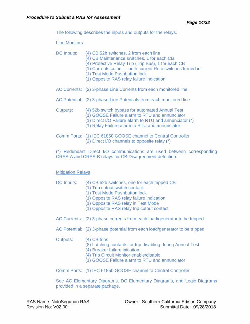
The following describes the inputs and outputs for the relays. Line Monitors DC Inputs: (4) CB 52b switches, 2 from each line (4) CB Maintenance switches, 1 for each CB (4) Protective Relay Trip (Trip Bus), 1 for each CB (1) Currents cut in — both current Roto switches turned in (1) Test Mode Pushbutton lock (1) Opposite RAS relay failure indication AC Currents: (2) 3-phase Line Currents from each monitored line AC Potential: (2) 3-phase Line Potentials from each monitored line Outputs: (4) 52b switch bypass for automated Annual Test (1) GOOSE Failure alarm to RTU and annunciator (1) Direct I/O Failure alarm to RTU and annunciator (*) (1) Relay Failure alarm to RTU and annunciator Comm Ports: (1) IEC 61850 GOOSE channel to Central Controller (2) Direct I/O channels to opposite relay (*) (*) Redundant Direct I/O communications are used between corresponding CRAS-A and CRAS-B relays for CB Disagreement detection. Mitigation Relays DC Inputs: (4) CB 52b switches, one for each tripped CB (1) Trip cutout switch contact (1) Test Mode Pushbutton lock (1) Opposite RAS relay failure indication (1) Opposite RAS relay in Test Mode (1) Opposite RAS relay trip cutout contact AC Currents: (2) 3-phase currents from each load/generator to be tripped AC Potential: (2) 3-phase potential from each load/generator to be tripped Outputs: (4) CB trips (8) Latching contacts for trip disabling during Annual Test (4) Breaker failure initiation (4) Trip Circuit Monitor enable/disable (1) GOOSE Failure alarm to RTU and annunciator Comm Ports: (1) IEC 61850 GOOSE channel to Central Controller See AC Elementary Diagrams, DC Elementary Diagrams, and Logic Diagrams provided in a separate package.
Procedure to Submit a RAS for Assessment Page 15/32
RAS Name: NidoSegundo RAS Owner: Southern California Edison Company Revision No: V02.00 Submittal Date: 09/28/2018
4) RAS Logic Hardware - Provide a description of the logic hardware (relay, digital computer, etc.) and describe how the RAS logic function is achieved.
The RAS logic hardware for the Line Monitoring and Tripping functions consists of
GE N60 relays. The N60 relay logic function is achieved through the use of programmable logic in the relays (GE FlexLogic). The RAS logic hardware for the Logic Processing function consists of 12 separate UAP (Unified Analytic Platform) Controllers. There are 6 UAP’s at the Alhambra site and 6 at the Irvine site. At each site there are 3 pairs of UAP’s, one primary and one standby; only 2 unpaired UAP’s on either A or B system are needed to make a mitigation decision to satisfy the 2-out-of-3 voting in the mitigation relays. These UAP’s run on HP Blade servers. The RAS logic function is achieved through the C++ programming.
5) Redundancy - Provide a discussion of the redundancy configuration and if
appropriate, why redundancy is not provided. Include discussion of redundant:
a) Detection. Redundant N60 Line Monitor relays are installed at all monitored line terminals to detect 220 kV line outages. A separate 52b switch input is provided to each N60 Line Monitor relay from each line circuit breaker. Each 52b switch has a separate bypass knife switch in the CB control cabinet. The current circuits for RAS-A and RAS-B Line Monitor relays are fed from separate current transformers. Each N60 relay monitors all three phase currents from each line for undercurrent supervision.
b) Power supplies, batteries and chargers.
Central Controller Installations: The Central Controllers are installed in diverse locations at Alhambra and Irvine. Both sites have dual power feeds and have battery backups for the complete installation. The batteries are sized to support the load for a minimum of 8 hours following the failure of both power feeds to the buildings. Once loss of both power feeds has been detected, the system has an onsite diesel generator that can back up the loss of power indefinitely. N60 Relay Installations: There is one substation battery system for each supply voltage. The batteries are sized to support the connected load for a minimum of 8 hours following the failure of the battery charger. CRAS-A and CRAS-B equipment are powered from separate circuit breaker protected dc source circuits. Each supply circuit is monitored by a separate under-voltage relay which provides alarm status to the SCADA and the local annunciator.
Procedure to Submit a RAS for Assessment Page 16/32
RAS Name: NidoSegundo RAS Owner: Southern California Edison Company Revision No: V02.00 Submittal Date: 09/28/2018
Telecomm: SCE Telecommunications uses a separate, negative 48-volt DC power system at each location shown on the block diagram. The DC system includes battery chargers with N-1 redundancy and batteries sized to support the load for a minimum of 8 hours in an AC-fail condition.
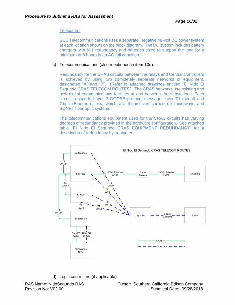
c) Telecommunications (also mentioned in item 10d). Redundancy for the CRAS circuits between the relays and Central Controllers is achieved by using two completely separate networks of equipment, designated “A” and “B”. (Refer to attached drawings entitled “El Nido El Segundo CRAS TELECOM ROUTES”. The CRAS networks use existing and new digital communications facilities at and between the substations. Each circuit transports Layer 2 GOOSE protocol messages over T1 (serial) and Gbps (Ethernet) links, which are themselves carried on microwave and SONET fiber optic systems. The telecommunications equipment used for the CRAS circuits has varying degrees of redundancy provided in the hardware configuration. See attached table “El Nido El Segundo CRAS EQUIPMENT REDUNDANCY” for a description of redundancy by equipment.
El Segundo
La Cienega
El Nido
La Fresa
Lighthipe
Alhambra
Irvine
Santa
Monica
CRAS “B”
CRAS “A”
El Segundo
NRG
T1
LW154
T1
LW154
T1
LW154
T1
LW70
Dark FO
OPGW
Dark FO
ADSS
T1
LW19
T1
LW19
T1
LW19T1
LW19
200Mb Ethernet
LW154
200Mb Ethernet
LW50
2 GigE
LW7008
El Nido El Segundo CRAS TELECOM ROUTES
d) Logic controllers (if applicable).
Procedure to Submit a RAS for Assessment Page 17/32
RAS Name: NidoSegundo RAS Owner: Southern California Edison Company Revision No: V02.00 Submittal Date: 09/28/2018
The Central Controller System consists of 12 separate UAP (Unified Analytic Platform) Controllers. There are 6 UAP’s at the Alhambra site and 6 at the Irvine site. At each site there are 3 pairs of UAP’s, one primary and one standby; only 2 unpaired UAP’s on either A or B system are needed to make a mitigation decision to satisfy the 2-out-of-3 voting in the mitigation relays.
e) RAS trip circuits.
Redundant CRAS-A and CRAS-B N60 Load Tripping relays are installed at El Nido and La Cienega substations. The relays close output contacts in response to tripping signals received from the CRAS Central Controllers. The relay contacts trip the appropriate circuit breakers and initiate breaker failure protection. The CRAS-A and CRAS-B trip circuits are fed from separately monitored and protected DC buses. Redundant CRAS-A and CRAS-B N60 Generator Tripping relays are installed at El Segundo Generating Station. The generator tripping function at El Segundo is separated into SCE-owned relays and NRG-owned relays that communicate with each other via dedicated single-mode fibers running between the SCE switchyard and the NRG generator relay room some 1500 feet away. This separation keeps the NERC-CIP portion of the relay communications system confined to the secured SCE substation, with the NRG-owned relays serving as remote tripping relays controlled by the SCE-owned relays. GE Direct I/O communications are used between the SCE and NRG relays to avoid any NERC-CIP concerns on the NRG side. When the SCE-owned relays receive a trip signal from the CRAS Central Controllers, they send a trip signal to the NRG-owned relays via the dedicated fiber. The NRG-owned relays close their trip output contacts when they receive a trip signal from the SCE-owned relays. The trip output contacts trip the appropriate generator breakers and initiate breaker failure protection. The CRAS-A and CRAS-B trip circuits are fed from separately monitored and protected DC buses.
6) Arming - Describe how the RAS is armed (i.e. remotely via SCADA, locally,
automatic, etc.
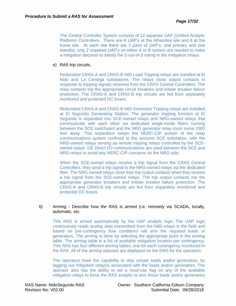
This RAS is armed automatically by the UAP analytic logic. The UAP logic continuously reads analog data transmitted from the N60 relays in the field and based on pre-contingency flow conditions will arm the required loads or generators. The arming is done by selecting the appropriate point in the arming table. The arming table is a list of available mitigation location per contingency. This RAS has four different arming tables, one for each contingency monitored in the RAS. All of the arming statuses are displayed on the EMS for the operators.
The operators have the capability to skip certain loads and/or generators, by tagging out mitigation relay(s) associated with the loads and/or generators. The operator also has the ability to set a must-use flag on any of the available mitigation relays to force the RAS analytic to arm those loads and/or generators
Procedure to Submit a RAS for Assessment Page 18/32
RAS Name: NidoSegundo RAS Owner: Southern California Edison Company Revision No: V02.00 Submittal Date: 09/28/2018
before others. Please see operator display below for a diagram of the RAS that is presented to the operators.
7) Detection - Define all inputs to the RAS for the scheme to perform its required
purpose. Examples:
a) Devices needed to determine line-end-status such as circuit breaker (52 a/b contacts) and disconnect status.
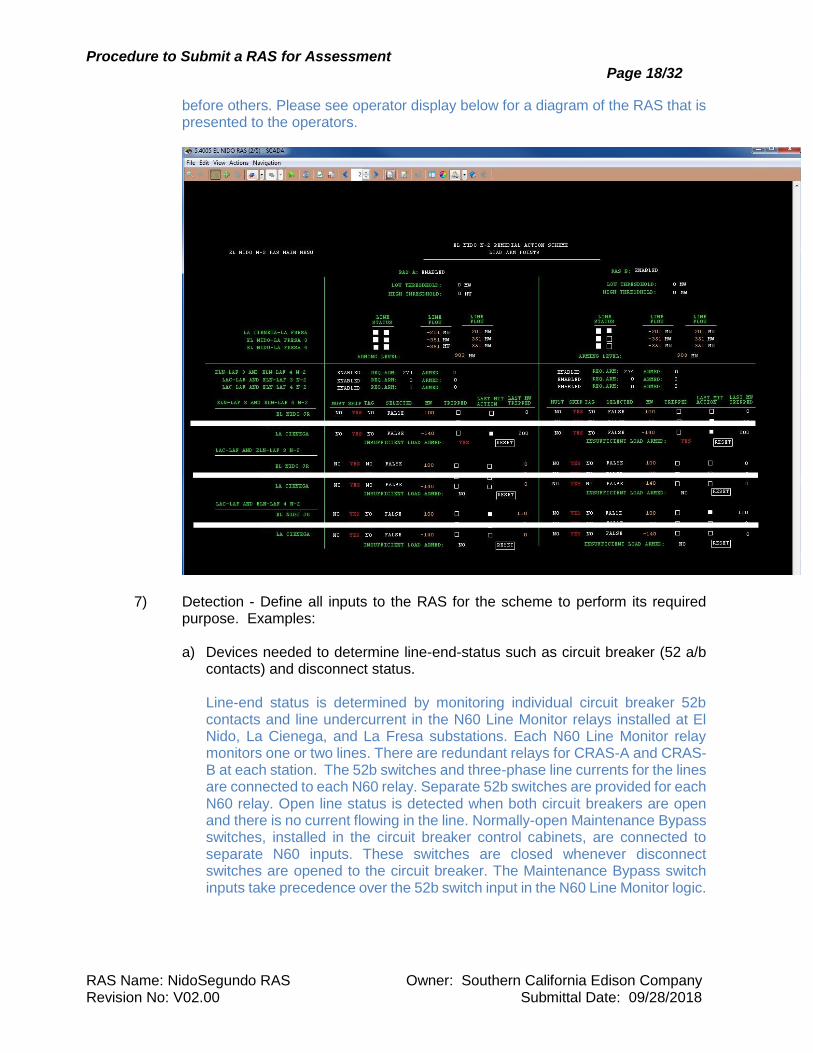
Line-end status is determined by monitoring individual circuit breaker 52b contacts and line undercurrent in the N60 Line Monitor relays installed at El Nido, La Cienega, and La Fresa substations. Each N60 Line Monitor relay monitors one or two lines. There are redundant relays for CRAS-A and CRAS-B at each station. The 52b switches and three-phase line currents for the lines are connected to each N60 relay. Separate 52b switches are provided for each N60 relay. Open line status is detected when both circuit breakers are open and there is no current flowing in the line. Normally-open Maintenance Bypass switches, installed in the circuit breaker control cabinets, are connected to separate N60 inputs. These switches are closed whenever disconnect switches are opened to the circuit breaker. The Maintenance Bypass switch inputs take precedence over the 52b switch input in the N60 Line Monitor logic.
Procedure to Submit a RAS for Assessment Page 19/32
RAS Name: NidoSegundo RAS Owner: Southern California Edison Company Revision No: V02.00 Submittal Date: 09/28/2018
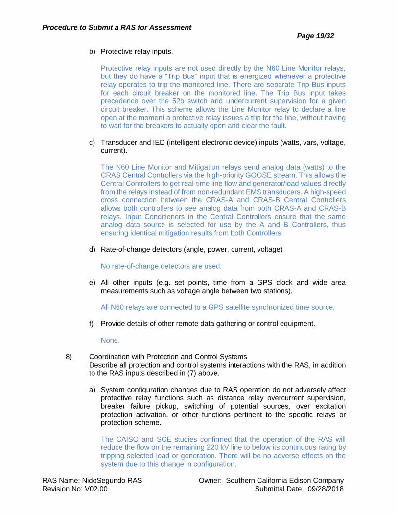
b) Protective relay inputs.
Protective relay inputs are not used directly by the N60 Line Monitor relays, but they do have a “Trip Bus” input that is energized whenever a protective relay operates to trip the monitored line. There are separate Trip Bus inputs for each circuit breaker on the monitored line. The Trip Bus input takes precedence over the 52b switch and undercurrent supervision for a given circuit breaker. This scheme allows the Line Monitor relay to declare a line open at the moment a protective relay issues a trip for the line, without having to wait for the breakers to actually open and clear the fault.
c) Transducer and IED (intelligent electronic device) inputs (watts, vars, voltage,
current).
The N60 Line Monitor and Mitigation relays send analog data (watts) to the CRAS Central Controllers via the high-priority GOOSE stream. This allows the Central Controllers to get real-time line flow and generator/load values directly from the relays instead of from non-redundant EMS transducers. A high-speed cross connection between the CRAS-A and CRAS-B Central Controllers allows both controllers to see analog data from both CRAS-A and CRAS-B relays. Input Conditioners in the Central Controllers ensure that the same analog data source is selected for use by the A and B Controllers, thus ensuring identical mitigation results from both Controllers.
d) Rate-of-change detectors (angle, power, current, voltage)
No rate-of-change detectors are used. e) All other inputs (e.g. set points, time from a GPS clock and wide area
measurements such as voltage angle between two stations).
All N60 relays are connected to a GPS satellite synchronized time source. f) Provide details of other remote data gathering or control equipment.
None.
8) Coordination with Protection and Control Systems Describe all protection and control systems interactions with the RAS, in addition to the RAS inputs described in (7) above. a) System configuration changes due to RAS operation do not adversely affect
protective relay functions such as distance relay overcurrent supervision, breaker failure pickup, switching of potential sources, over excitation protection activation, or other functions pertinent to the specific relays or protection scheme. The CAISO and SCE studies confirmed that the operation of the RAS will reduce the flow on the remaining 220 kV line to below its continuous rating by tripping selected load or generation. There will be no adverse effects on the system due to this change in configuration.
Procedure to Submit a RAS for Assessment Page 20/32
RAS Name: NidoSegundo RAS Owner: Southern California Edison Company Revision No: V02.00 Submittal Date: 09/28/2018
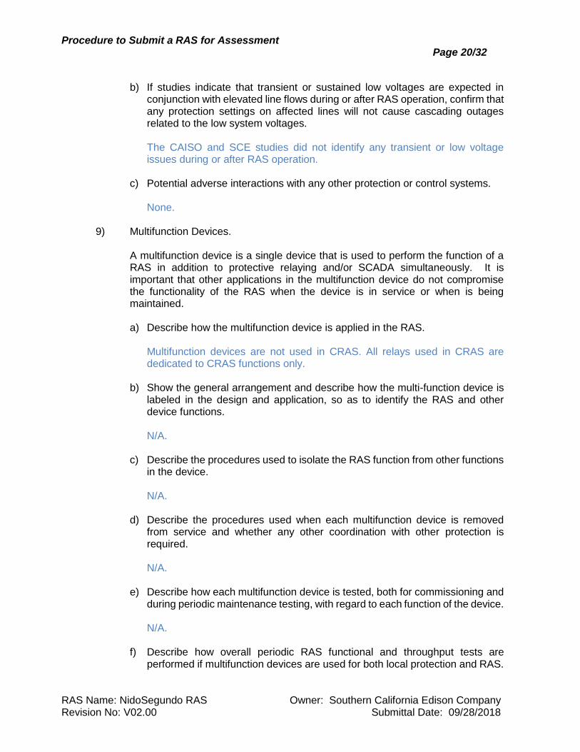
b) If studies indicate that transient or sustained low voltages are expected in
conjunction with elevated line flows during or after RAS operation, confirm that any protection settings on affected lines will not cause cascading outages related to the low system voltages. The CAISO and SCE studies did not identify any transient or low voltage issues during or after RAS operation.
c) Potential adverse interactions with any other protection or control systems.
None. 9) Multifunction Devices.
A multifunction device is a single device that is used to perform the function of a RAS in addition to protective relaying and/or SCADA simultaneously. It is important that other applications in the multifunction device do not compromise the functionality of the RAS when the device is in service or when is being maintained. a) Describe how the multifunction device is applied in the RAS.
Multifunction devices are not used in CRAS. All relays used in CRAS are dedicated to CRAS functions only.
b) Show the general arrangement and describe how the multi-function device is labeled in the design and application, so as to identify the RAS and other device functions. N/A.
c) Describe the procedures used to isolate the RAS function from other functions in the device. N/A.
d) Describe the procedures used when each multifunction device is removed from service and whether any other coordination with other protection is required. N/A.
e) Describe how each multifunction device is tested, both for commissioning and during periodic maintenance testing, with regard to each function of the device. N/A.
f) Describe how overall periodic RAS functional and throughput tests are performed if multifunction devices are used for both local protection and RAS.
Procedure to Submit a RAS for Assessment Page 21/32
RAS Name: NidoSegundo RAS Owner: Southern California Edison Company Revision No: V02.00 Submittal Date: 09/28/2018
N/A.
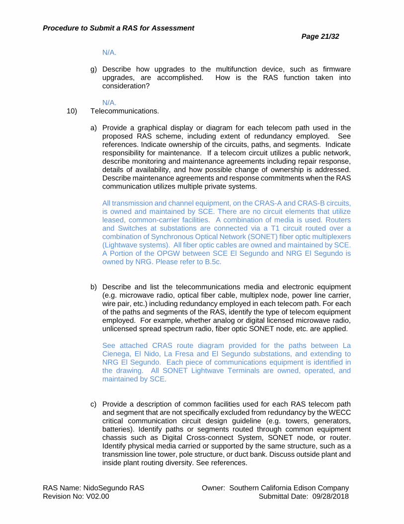
g) Describe how upgrades to the multifunction device, such as firmware upgrades, are accomplished. How is the RAS function taken into consideration?
N/A.
10) Telecommunications.
a) Provide a graphical display or diagram for each telecom path used in the proposed RAS scheme, including extent of redundancy employed. See references. Indicate ownership of the circuits, paths, and segments. Indicate responsibility for maintenance. If a telecom circuit utilizes a public network, describe monitoring and maintenance agreements including repair response, details of availability, and how possible change of ownership is addressed. Describe maintenance agreements and response commitments when the RAS communication utilizes multiple private systems.
All transmission and channel equipment, on the CRAS-A and CRAS-B circuits, is owned and maintained by SCE. There are no circuit elements that utilize leased, common-carrier facilities. A combination of media is used. Routers and Switches at substations are connected via a T1 circuit routed over a combination of Synchronous Optical Network (SONET) fiber optic multiplexers (Lightwave systems). All fiber optic cables are owned and maintained by SCE. A Portion of the OPGW between SCE El Segundo and NRG El Segundo is owned by NRG. Please refer to B.5c.
b) Describe and list the telecommunications media and electronic equipment
(e.g. microwave radio, optical fiber cable, multiplex node, power line carrier, wire pair, etc.) including redundancy employed in each telecom path. For each of the paths and segments of the RAS, identify the type of telecom equipment employed. For example, whether analog or digital licensed microwave radio, unlicensed spread spectrum radio, fiber optic SONET node, etc. are applied. See attached CRAS route diagram provided for the paths between La Cienega, El Nido, La Fresa and El Segundo substations, and extending to NRG El Segundo. Each piece of communications equipment is identified in the drawing. All SONET Lightwave Terminals are owned, operated, and maintained by SCE.
c) Provide a description of common facilities used for each RAS telecom path
and segment that are not specifically excluded from redundancy by the WECC critical communication circuit design guideline (e.g. towers, generators, batteries). Identify paths or segments routed through common equipment chassis such as Digital Cross-connect System, SONET node, or router. Identify physical media carried or supported by the same structure, such as a transmission line tower, pole structure, or duct bank. Discuss outside plant and inside plant routing diversity. See references.
Procedure to Submit a RAS for Assessment Page 22/32
RAS Name: NidoSegundo RAS Owner: Southern California Edison Company Revision No: V02.00 Submittal Date: 09/28/2018
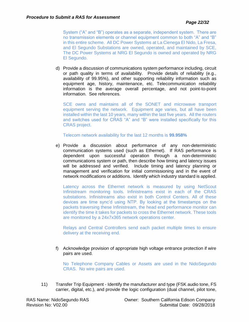
System (“A” and “B”) operates as a separate, independent system. There are no transmission elements or channel equipment common to both “A” and “B” in this entire scheme. All DC Power Systems at La Cienega El Nido, La Fresa, and El Segundo Substations are owned, operated, and maintained by SCE, The DC Power Systems at NRG El Segundo is owned and operated by NRG El Segundo.
d) Provide a discussion of communications system performance including, circuit
or path quality in terms of availability. Provide details of reliability (e.g., availability of 99.95%), and other supporting reliability information such as equipment age, history, maintenance, etc. Telecommunication reliability information is the average overall percentage, and not point-to-point information. See references. SCE owns and maintains all of the SONET and microwave transport equipment serving the network. Equipment age varies, but all have been installed within the last 10 years, many within the last five years. All the routers and switches used for CRAS “A” and “B” were installed specifically for this CRAS project. Telecom network availability for the last 12 months is 99.958%
e) Provide a discussion about performance of any non-deterministic
communication systems used (such as Ethernet). If RAS performance is dependent upon successful operation through a non-deterministic communications system or path, then describe how timing and latency issues will be addressed and verified. Include timing and latency planning or management and verification for initial commissioning and in the event of network modifications or additions. Identify which industry standard is applied. Latency across the Ethernet network is measured by using NetScout Infinistream monitoring tools. Infinistreams exist in each of the CRAS substations. Infinistreams also exist in both Control Centers. All of these devices are time sync’d using NTP. By looking at the timestamps on the packets traversing these Infinistream, the head end performance monitor can identify the time it takes for packets to cross the Ethernet network. These tools are monitored by a 24x7x365 network operations center. Relays and Central Controllers send each packet multiple times to ensure delivery at the receiving end.
f) Acknowledge provision of appropriate high voltage entrance protection if wire
pairs are used. No Telephone Company Cables or Assets are used in the NidoSegundo CRAS. No wire pairs are used.
11) Transfer Trip Equipment - Identify the manufacturer and type (FSK audio tone, FS carrier, digital, etc.), and provide the logic configuration (dual channel, pilot tone,
Procedure to Submit a RAS for Assessment Page 23/32
RAS Name: NidoSegundo RAS Owner: Southern California Edison Company Revision No: V02.00 Submittal Date: 09/28/2018
etc.). Identify whether internal device medium is used; e.g. “Relay-to-Relay” communication.
Transfer Trip equipment is not used in CRAS. Communication between the CRAS Central Controllers and the N60 Line Monitors and Tripping relays uses wide-area GOOSE carried over T1 circuits.
12) Remedial Actions Initiated - Provide a functional description of the action(s)
produced by the scheme and include a simplified one-line diagram of the RAS
output to the end-device operated by the scheme.
During times of high El Segundo generator output and low El Nido area load (eastbound power flow), loss of the two El Nido – La Fresa 220 kV lines will cause a thermal overload on the El Nido – La Cienega 220 kV line. The RAS action for this contingency under these system conditions is to trip two generators (units 5 & 6, or units 7 & 8) at El Segundo. During times of low El Segundo generator output and high El Nido area load (westbound power flow from La Fresa to El Nido), loss of any two 220 kV lines west of La Fresa will cause a thermal overload of the remaining line. The RAS action for these contingencies under these system conditions is to trip load at El Nido and/or La Cienega. See diagrams in Section A7.
13) Remedial Action Schemes may have elements such as engineering access,
routable protocols, and sensitive design documentation included in the design that require compliance with the NERC CIP Standards. Utilities may handle CIP compliance differently. Please provide a high level overview of how your company’s CIP Compliance Program requirements are incorporated into this RAS design.
The RASRS concern is that CIP compliance does not compromise the reliability of the RAS. RASRS will not assess compliance, validity or completeness of the owner’s CIP program. The owner remains completely and solely responsible that its CIP program complies with NERC standards.
SCE will complete the following In order to declare the CRAS System as NERC CIP compliant:
i. Satisfy NERC CIP Requirements (CIP 002 through CIP 009) 1. Gather evidence for review & approval:
a. CRAS Central Assets (Devices and Applications at the Control Centers)
b. CRAS Edge Assets (Relays and Gateways at the Substations)
c. Telecom equipment d. Corporate Security
2. Leverage existing SCE EMS CIP Compliance Processes & Procedures.
Procedure to Submit a RAS for Assessment Page 24/32
RAS Name: NidoSegundo RAS Owner: Southern California Edison Company Revision No: V02.00 Submittal Date: 09/28/2018
3. Develop and roll-out Additional Processes & Procedures for maintenance Substation assets
4. Receive approval from SCE Corporate Compliance groups ii. Ensure Electronic Security Perimeter (ESP) is in place (CIP 005) iii. Ensure Physical Security Perimeter (PSP) is in place (CIP 006) iv. Approve Delegation Agreements (requirement of CIP 003 R2.3) v. Approve TFEs internally and submit to WECC vi. Approve ESP & PSP access for CRAS Central and Edge Assets
C. MONITORING
1) Provide details of RAS monitoring equipment and time resolution including station
alarms, SCADA monitoring, and Sequence of Events Recorders.
The N60 relays record internal events with a time resolution of 1 millisecond or better. All N60 events will be sent to the SCE’s EMS system on a continuous basis. Any change in state of alarm points in the relays will alarm Grid Control Center and Substation Operations personnel. The alarming will automatically log into the EMS alarm and events summaries with UAP location, date, time, and the specific alarm point. All alarms and events will also be stored in the eDNA historian.
The RAS active UAP’s events will be continually sent to the SCE’s EMS system. Any change in state of alarm points in the UAP will alarm Grid Control Center and Substation Operations personnel. The alarming will automatically log into the EMS alarm and events summaries with UAP location, date, time, and the specific alarm point. All alarms and events will also be stored in the eDNA historian.
2) Provide details of facilities monitored including
a) Equipment self-diagnostics and annunciation
All of the relays are microprocessor-based with self-diagnostics and internal event monitoring. The relay internal trouble alarm contact is monitored by the local annunciator panel and the RTU, and it is also connected to an input on the redundant-system relay so that the CRAS Central Controllers are also aware of the relay failure. GOOSE and Direct I/O failures are also monitored by the station annunciator and RTU. The UAP Controllers are HP Blade Servers with self-diagnostics and internal event monitoring. Any change in state of alarm points in the UAP will alarm Grid Control Center and Substation Operations personnel. The alarming will automatically cause annunciation for the operators in the field and at the GCC.
b) Initiation locations
Line monitor relays transmit bits in their outbound GOOSE messages to provide alarms for CB Disagreement and CB Error. The relays also record these events in their internal event records.
Procedure to Submit a RAS for Assessment Page 25/32
RAS Name: NidoSegundo RAS Owner: Southern California Edison Company Revision No: V02.00 Submittal Date: 09/28/2018
c) Logic facilities
See section C 2a above.
d) Telecommunications Personnel at SCE’s Telecommunications Control Center (TCC) use a “manager of managers” system, IBM Netcool, to monitor network status and conditions throughout SCE’s service territory on a 24x7 basis. The TCC is responsible for problem analysis and dispatch and coordination of SCE Telecommunications technicians and outside plant forces to resolve problems and alarm conditions. Maintenance and repair technicians are based at 15 locations located throughout the SCE service territory. All circuits in service are tracked in a circuit database. The TCC assigns a response priority within the database to each circuit when it is placed into service. The response priority governs TCC actions when a circuit fails. CRAS circuits are assigned a priority 1 response classification, which requires a two (2) hour response time. This is the highest priority available, and the same as that used for transfer trip circuits.
e) Transfer trip equipment
No external transfer trip equipment is used by CRAS. g) RAS actions
RAS trips are monitored by the UAP’s and both locations and saved in the eDNA historian for all actions.
N60 Line Monitor relays trigger oscillography recording whenever one of the monitored lines opens. The N60 Mitigation relays trigger oscillography recording whenever the relay receives a trip command (verified by the 2-out-of-three voting logic, and excluding annual end-to-end tests). RMS voltages and currents are recorded by the relays, along with a variety of digital points. All Alarms and Events from RAS actions are sent to the EMS XA/21 system for evaluation and display for the System operators. These are transmitted to the EMS system via ICCP and displayed for the operators via RAS displays and Alarm/Event summaries.
D. RAS OPERATING PROCEDURES FOR ABNORMAL SYSTEM CONDITIONS
Provide a summary of the operating procedures or the relevant Dispatch Instructions pertaining to this RAS during abnormal system conditions. Specifically address the operating procedures for the following situations: 1) The RAS operates incorrectly (failure to operate or false operation).
Procedure to Submit a RAS for Assessment Page 26/32
RAS Name: NidoSegundo RAS Owner: Southern California Edison Company Revision No: V02.00 Submittal Date: 09/28/2018
If CRAS-A or CRAS-B fails to operate for any reason, the CRAS system that has failed will be taken out of service for test and repair within 22 hours. Repairs or replacement will be completed within 20 business days. If CRAS-A or CRAS-B operates falsely for any reason, the CRAS system that operated falsely will be taken out of service for test and repair within 22 hours. Repairs or replacement will be completed within 20 business days.
2) One part of a redundant RAS system is unavailable so that complete redundancy
is no longer assured. If any part of CRAS-A or CRAS-B is unavailable due to failure of a relay or communications channel, the failed component will be repaired or replaced within 20 business days.
3) Unscheduled, or unplanned and not coordinated, unavailability of the subject RAS
(complete loss of RAS) impacts operation. Any time the RAS becomes unavailable or an event occurs that makes load or generator tripping partially or totally unavailable, the GCC Transmission Dispatchers will expedite the return of any associated equipment that may be out of service. If the RAS arming thresholds are expected to be exceeded during the outage, the GCC will request the CAISO to re-dispatch El Segundo generation as needed, or will roll load as needed to adjacent sub-transmission systems. During times of high eastbound power flow (El Segundo generation at high level), generation curtailment will be the normal course of action for complete loss of the RAS. During times of high westbound power flow (El Segundo generation at low level or off-line), the normal course of action will be to either increase El Segundo generation if possible, or roll load as needed to adjacent sub-transmission systems.
4) When a partial or total loss of input data required for arming decisions.
While CRAS-A and CRAS-B are separate, redundant installations, to ensure that they are arriving at the same arming decisions, they share information. Each line segment is monitored by four monitoring relays, one at each end for each RAS system. The CRAS system then uses the input from each end to determine what value to use for calculation of the correct arming. Typically, this is the maximum of the four monitored points. The loss of two of the four relays used for arming calculations would be acceptable for arming calculations. However, if both relays are on the same end of the line it raises a possibility that the system would not be able to identify a line out. Therefore, upon the loss of both relays on one end of the line, RAS A and RAS B monitoring relay, the contingencies using the information provided by the relays should be made non-operational
Procedure to Submit a RAS for Assessment Page 27/32
RAS Name: NidoSegundo RAS Owner: Southern California Edison Company Revision No: V02.00 Submittal Date: 09/28/2018
E. COMMISSIONING, MAINTENANCE AND TESTING
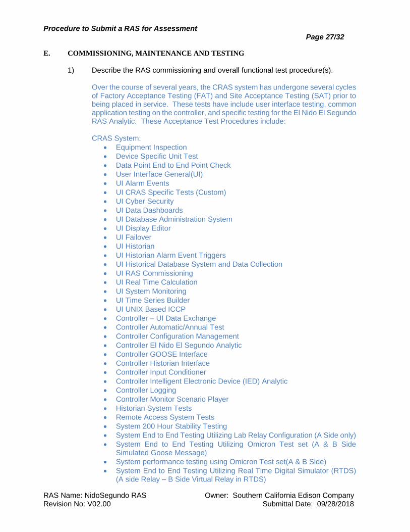
1) Describe the RAS commissioning and overall functional test procedure(s).
Over the course of several years, the CRAS system has undergone several cycles of Factory Acceptance Testing (FAT) and Site Acceptance Testing (SAT) prior to being placed in service. These tests have include user interface testing, common application testing on the controller, and specific testing for the El Nido El Segundo RAS Analytic. These Acceptance Test Procedures include: CRAS System:
• Equipment Inspection
• Device Specific Unit Test
• Data Point End to End Point Check
• User Interface General(UI)
• UI Alarm Events
• UI CRAS Specific Tests (Custom)
• UI Cyber Security
• UI Data Dashboards
• UI Database Administration System
• UI Display Editor
• UI Failover
• UI Historian
• UI Historian Alarm Event Triggers
• UI Historical Database System and Data Collection
• UI RAS Commissioning
• UI Real Time Calculation
• UI System Monitoring
• UI Time Series Builder
• UI UNIX Based ICCP
• Controller – UI Data Exchange
• Controller Automatic/Annual Test
• Controller Configuration Management
• Controller El Nido El Segundo Analytic
• Controller GOOSE Interface
• Controller Historian Interface
• Controller Input Conditioner
• Controller Intelligent Electronic Device (IED) Analytic
• Controller Logging
• Controller Monitor Scenario Player
• Historian System Tests
• Remote Access System Tests
• System 200 Hour Stability Testing
• System End to End Testing Utilizing Lab Relay Configuration (A Side only)
• System End to End Testing Utilizing Omicron Test set (A & B Side Simulated Goose Message)
• System performance testing using Omicron Test set(A & B Side)
• System End to End Testing Utilizing Real Time Digital Simulator (RTDS) (A side Relay – B Side Virtual Relay in RTDS)
Procedure to Submit a RAS for Assessment Page 28/32
RAS Name: NidoSegundo RAS Owner: Southern California Edison Company Revision No: V02.00 Submittal Date: 09/28/2018
• System Performance Testing
Individual test plans and test plan results are available on request due to the significant volume of the system test plan.
RAS Analytic:
• Verify Analytic functionality by utilizing RTDS and virtual GE relays in a test environment.
• Verify all virtual relays contain field relay settings.
• Run numerous scenarios, proving all mitigating combinations.
• Once proven in the test environment, run selected end-to-end tests with field relays to verify analytic functionality in the production environment.
Telecomm:
• Test all circuits for continuity
• Verify that all communications channels are operating correctly
• Measure communication time delay and overall system operating time delay
• Verify VLAN configuration within each Substation
• Verify IP connectivity to each Substation
• Verify QoS Configuration Relays: During relay commissioning tests, SCE technicians will perform the following tasks with respect to the N60 Line Monitor and Tripping relays:
• Verify all wiring prints match the elementary diagrams and make corrections if required
• Verify that all physical wiring matches the wiring prints
• Test all circuits for continuity
• Verify that all RAS equipment settings are correct
• Verify all relay calibration settings
• Verify that all relay logic settings match the logic diagrams
• Verify that all relay logic inputs, outputs, timers, and gates are functioning properly by testing electrically and monitoring the internal logic points with monitoring software
• Verify that all communications channels are operating correctly
• Verify all annunciator and RTU alarm points 2) Describe the maintenance and test procedures including:
a) The provision of test switches and test facilities.
Manually-operated Electroswitch Series 24 rotary switches are installed in the DC supply circuits of all relays. Electrically operable Electroswitch Latching Switch Relays (LSRs) are installed for each N60 Tripping relay to cutout the tripping function.
Procedure to Submit a RAS for Assessment Page 29/32
RAS Name: NidoSegundo RAS Owner: Southern California Edison Company Revision No: V02.00 Submittal Date: 09/28/2018
ABB FT potential type switches are installed in relay DC control circuits, and FT current type switches and Meter Devices Roto Test switches are installed in current circuits, to allow technicians to isolate the equipment for testing.
b) Preventative maintenance; both electrical and telecommunication.
Electrical preventative maintenance is provided by performing an annual end-to-end test between each CRAS relay and the Central Controllers using the Annual Test CRAS analytic, and by performing routine testing on the relays every two years. The Central Controller (UAP) sends a ping to each IED in a substation on a rotating basis. These pings are sent on a period of 60 second intervals (this is a configurable time interval) to one IED at each substation, all IED’s are pinged in a substation before they are all pinged again. This will discover if there is a problem with one of the IED’s at the substation. From this ping an alarm will be generated and sent to the operator so that maintenance can go and repair the problem with the IED. Preventative maintenance of circuit breaker trip circuits is provided by utilizing a Trip Circuit Monitor feature incorporated into the N60 Mitigation relays. The Mitigation relays monitor the health of the trip circuits through the use of built-in voltage monitoring in the relay trip output contacts. Anything that causes loss of the negative voltage feedback from the breaker trip circuit to the relay, including an open trip coil, a failed 52a contact, or a broken wire, while the breaker is closed, will cause the Trip Circuit Monitor to send an alarm to the Central Controller. Maintenance personnel can then be dispatched to the station to investigate and repair the failed trip circuit. Continuously monitoring the health of the entire breaker trip circuit helps ensure a high level of reliability and availability of the trip circuit. Telecom: Rather than employ a preventative maintenance program at the circuit level, SCE Telecom relies on a process that includes rigorous circuit testing upon commissioning, continuous monitoring of equipment and site alarms, and responding quickly to alarms and reported failures. Microwave transport systems are maintained regularly to ensure compliance with applicable FCC regulations.
c) Functional Testing, including system end-to-end checks
• Verify that all RAS equipment settings are correct
• Verify that all relay logic settings match the RAS logic diagrams
• Verify that all relay logic inputs, outputs, timers, and gates are functioning properly by testing electrically and monitoring the internal logic points with monitoring software
• Verify that all communications circuits are functioning properly
• Verify all relay calibration settings
• Verify successful execution of the Annual Test CRAS analytic
Procedure to Submit a RAS for Assessment Page 30/32
RAS Name: NidoSegundo RAS Owner: Southern California Edison Company Revision No: V02.00 Submittal Date: 09/28/2018
d) Provide the maintenance and test intervals, including any seasonal restrictions.
RAS systems are maintained every two years per CAISO requirements. Functional, calibration, and overall test are performed on RAS systems. The annual test CRAS analytic will be performed once a year to verify the CRAS functionality.
e) A copy of the Maintenance and Test Procedure(s).
Will provide upon request.
f) A discussion of power system curtailment during maintenance and test activities
The RAS will be tested during a time when power flows in the area are not expected to reach arming levels. If arming levels are reached while both CRAS-A and CRAS-B are out of service, the steps outlined in section D1c will be followed.
F. PERFORMANCE AND OPERATIONAL HISTORY
1) Provide assurances that the overall performance and operating time of the RAS
will meet the requirements identified in system studies.
The CAISO and SCE studies did not identify any stability or voltage issues. This RAS is needed for thermal overload protection only. The overloaded transmission line can withstand the worst-case overload for at least 30 seconds. The RAS is designed to wait two seconds after the occurrence of a triggering contingency before tripping load or generation to allow for line reclosing to relieve the overload.
2) When using the existing equipment and components, such as the EMS, RAS
controllers, and arming devices, address the following items as they pertain to the operational history of such equipment and procedures. a) How long has the RAS been in operation and how many times has it operated?
This CRAS has been in service since 04/2016. It has never operated. b) How many times has the RAS failed to operate when it should have? Provide
details of causes and impacts.
N/A. c) How many times has it operated unnecessarily? Provide details of causes and
impacts.
N/A. d) What modifications, if any, are planned as a result of b and c above?
N/A.
Procedure to Submit a RAS for Assessment Page 31/32
RAS Name: NidoSegundo RAS Owner: Southern California Edison Company Revision No: V02.00 Submittal Date: 09/28/2018
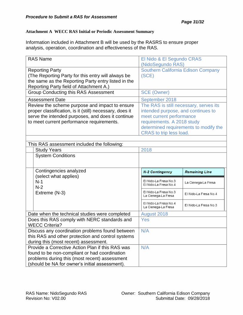
Attachment A WECC RAS Initial or Periodic Assessment Summary
Information included in Attachment B will be used by the RASRS to ensure proper analysis, operation, coordination and effectiveness of the RAS.
RAS Name El Nido & El Segundo CRAS (NidoSegundo RAS)
Reporting Party (The Reporting Party for this entry will always be the same as the Reporting Party entry listed in the Reporting Party field of Attachment A.)
Southern California Edison Company (SCE)
Group Conducting this RAS Assessment SCE (Owner)
Assessment Date September 2018
Review the scheme purpose and impact to ensure proper classification, is it (still) necessary, does it serve the intended purposes, and does it continue to meet current performance requirements.
The RAS is still necessary, serves its intended purpose, and continues to meet current performance requirements. A 2018 study determined requirements to modify the CRAS to trip less load.
This RAS assessment included the following:
Study Years 2018
System Conditions
Contingencies analyzed (select what applies) N-1 N-2 Extreme (N-3)
Date when the technical studies were completed August 2018
Does this RAS comply with NERC standards and WECC Criteria?
Yes
Discuss any coordination problems found between this RAS and other protection and control systems during this (most recent) assessment.
N/A
Provide a Corrective Action Plan if this RAS was found to be non-compliant or had coordination problems during this (most recent) assessment (should be NA for owner’s initial assessment).
N/A
Procedure to Submit a RAS for Assessment Page 32/32
RAS Name: NidoSegundo RAS Owner: Southern California Edison Company Revision No: V02.00 Submittal Date: 09/28/2018
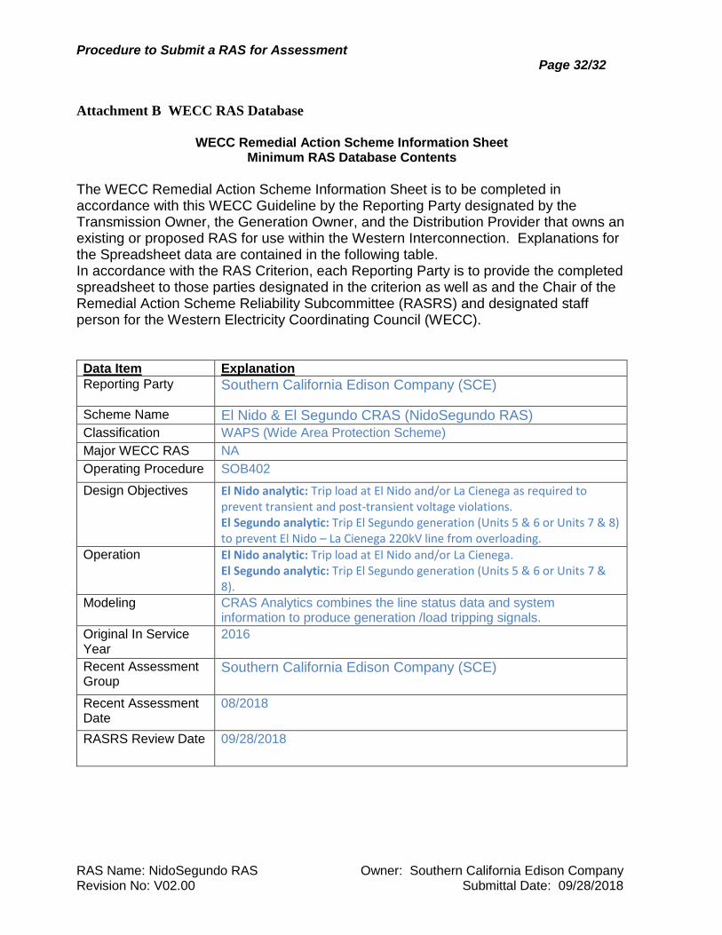
Attachment B WECC RAS Database
WECC Remedial Action Scheme Information Sheet
Minimum RAS Database Contents
The WECC Remedial Action Scheme Information Sheet is to be completed in accordance with this WECC Guideline by the Reporting Party designated by the Transmission Owner, the Generation Owner, and the Distribution Provider that owns an existing or proposed RAS for use within the Western Interconnection. Explanations for the Spreadsheet data are contained in the following table. In accordance with the RAS Criterion, each Reporting Party is to provide the completed spreadsheet to those parties designated in the criterion as well as and the Chair of the Remedial Action Scheme Reliability Subcommittee (RASRS) and designated staff person for the Western Electricity Coordinating Council (WECC). Data Item Explanation
Reporting Party
Southern California Edison Company (SCE)
Scheme Name El Nido & El Segundo CRAS (NidoSegundo RAS)
Classification WAPS (Wide Area Protection Scheme)
Major WECC RAS NA
Operating Procedure SOB402
Design Objectives El Nido analytic: Trip load at El Nido and/or La Cienega as required to prevent transient and post-transient voltage violations. El Segundo analytic: Trip El Segundo generation (Units 5 & 6 or Units 7 & 8) to prevent El Nido – La Cienega 220kV line from overloading.
Operation El Nido analytic: Trip load at El Nido and/or La Cienega. El Segundo analytic: Trip El Segundo generation (Units 5 & 6 or Units 7 & 8).
Modeling CRAS Analytics combines the line status data and system information to produce generation /load tripping signals.
Original In Service Year
2016
Recent Assessment Group
Southern California Edison Company (SCE)
Recent Assessment Date
08/2018
RASRS Review Date 09/28/2018