Embed Size (px)
Citation preview
Revision 1.4 WebSwitch™ Users Manual
Contents
Trademark and Copyright Information
Warranty
FCC Statement
Installation Guidelines (Read Before Installing)
Section 1: Introduction
1.1 Features
1.2 Applications
1.3 WebSwitch™ Models Available1.3.1 Optional Accessories
1.4 Connectors & Indicators
1.5 Accessing WebSwitch™
Section 2: Installation and Setup
2.1 Mounting
2.2 Connection2.2.1 Power Supply Connection2.2.2 Outlet Connection2.2.3 Network Connection2.2.4 Terminal Connector
2.3 Establishing Communications for Setup2.3.1 Option 1: Assign a temporary IP address to WebSwitch™2.3.2 Option 2: Assign a temporary IP address to configuration computer2.3.3 Open Configuration Web Page
2.4 WebSwitch™ Setup Pages2.4.1 Main Tab2.4.2 Network Tab2.4.3 Advanced Network Tab2.3.3 2.4.4 Password Tab2.4.5 Date/Time Tab2.4.6 Logging Tab2.4.7 Outlets Tab2.4.8 Inputs Tab 2.4.9 Sensors Tab2.4.10 Events Scheduler Tab 2.4.11 Script Tab2.4.12 Control Page Setup Tab
Xytronix Research & Design, Inc. 1
Revision 1.4 WebSwitch™ Users Manual
Section 3: Operation
3.1 Browser Operation
3.2 XML Operation3.2.1 Controlling the unit through state.xml3.2.2 GET Requests3.2.3 Monitoring Events through eventX.xml3.2.4 XML Diagnostics
3.3 Configuring Events Through Get Requests
3.4 Modbus Operation3.4.1 Read Coils (Modbus Function Code 01 (0x01))3.4.2 Read Discrete Inputs (Modbus Function Code 02 (0x02))3.4.3 Read Holding Registers (Modbus Function Code 03 (0x03))3.4.4 Write Single Coil (Modbus Function Code 05 (0x05))3.4.5 Write Multiple Coils (Modbus Function Code 15 (0x0F))3.4.6 Write Multiple Registers (Modbus Function Code 16 (0x10))
3.5 Email Notification3.5.1 Email Notification Description3.5.2 Email Notification Setup
Appendix
Appendix A: Restoring Factory Default Settings
Appendix B: Installing New Firmware
Appendix C: Accessing WebSwitch™ Remotely Over the Internet
Appendix D: External Server and Remote Services
Appendix E: Log Files
Appendix F: SNMP Requests, Objects and Community Strings
Appendix G: BASIC Scripts
Appendix H: Specifications
Appendix I: Mechanical Information
Xytronix Research & Design, Inc. 2

Revision 1.4 WebSwitch™ Users Manual
Trademark and Copyright InformationThis document is Copyright ©2010-2017 by Xytronix Research & Design, Inc. All rights reserved.
WebSwitch™, WebRelay™, ControlByWeb™, and Xytronix Research & Design™ are trademarks of Xytronix Research & Design™, Inc. 2010-2017.
All parts of this product and design including but not limited to firmware, hardware design, schematics, PCB layout, concept, graphics, users manual, etc., are property of Xytronix Research & Design, Inc. ©2010-2017 . WebSwitch™ may not be opened, disassembled, copied or reverse-engineered.
No part of this manual may be reproduced or transmitted in any form or by any means, electronic or mechanical, including photocopying or scanning, for any purpose other than the personal use by the purchaser of this product. Xytronix Research & Design, Inc., assumes no responsibility for any errors that may appear in this document.
Whereas reasonable effort has been made to make the information in this document as useful and accurate as possible, Xytronix Research & Design, Inc. assumes no responsibility for the application, usefulness, or completeness of the information contained herein. Under no circumstance will Xytronix Research & Design, Inc. be responsible or liable for any damages or losses including direct, indirect, special, incidental, or consequential damages or losses arising from either the use of any information contained within this manual or the use of any products or services referenced in this manual.
Xytronix Research & Design, Inc. reserves the right to change any product’s features, specifications, documentation, warranties, fee schedules, and conditions at any time and without notice.
Xytronix Research & Design, Inc. 3

Revision 1.4 WebSwitch™ Users Manual
WarrantyThis Xytronix Research & Design, Inc. product has a warranty against defects in material and workmanship for a period of one year from the date of shipment. During the warranty period, Xytronix Research & Design, Inc. will, at its option, either repair or replace products that prove to be defective. This warranty is extended to the original purchaser of the equipment only.
For warranty service or repair, the product must be properly packaged, and returned to Xytronix Research & Design, Inc. The purchaser shall prepay all charges for shipping to Xytronix Research & Design, Inc., and Xytronix Research & Design, Inc. will pay the shipping charges to return the product to the purchaser as long as the product is shipped within the United States. If the product is shipped outside of the United States, the purchaser shall pay all shipping charges, duties, and taxes.
Limitation
The foregoing warranty shall not apply to defects or damage resulting from improper use or misuse, unauthorized repair, tampering, modification, improper connection, or operation outside the electrical/environmental specifications for the product. Further, the warranty does not cover Acts of God, such as fire, flood, hurricanes, and tornadoes. This warranty does not cover damage to property, equipment, direct, indirect, consequential, or incidental damage (including damage for loss of business profit, business interruption, loss of data, and the like) arising out of the use or misuse of this product.
UNDER NO CIRCUMSTANCES WILL THE LIABILITY OF XYTRONIX RESEARCH & DESIGN, INC. TOTHE PURCHASER OR ANY OTHER PARTY EXCEED THE ORIGINAL PURCHASE PRICE OF THE PRODUCT, REGARDLESS OF THE FORM OF THE CLAIM. No other warranty is expressed or implied.Xytronix Research & Design, Inc. specifically disclaims the implied warranties or merchantability and fitness for a particular purpose. Some jurisdictions may not allow the exclusion of limitation of liability for consequential or incidental damage.
Xytronix Research & Design, Inc. 4

Revision 1.4 WebSwitch™ Users Manual
FCC Statement This device complies with Part 15 of the FCC Rules. Operation is subject to the following two conditions:
━ This device may not cause harmful interference.━ This device must accept any interference received, including interference that may cause undesired
operation.
Warning
This equipment has been tested and found to comply with the limits for a Class B digital device, pursuant to Part 15 of the FCC Rules. These limits are designed to provide reasonable protection. This equipment generates, uses and can radiate radio frequency energy and, if not installed and used in accordance with the instructions, may cause interference to radio communications. There is no guarantee, however, that interference will not occur in a particular installation. If this equipment does cause harmful interference to radio or television reception, which can be determined by turning the equipment off and on, the user is encouraged to try to correct the interference by one or more of the following measures:
━ Reorient or relocate the receiving antenna.━ Increase the separation between the equipment and receiver.━ Connect the equipment into an outlet on a circuit different from that to which the receiver is
connected.━ Consult the dealer or an experienced radio/TV technician for help.
Notice
Changes or modification not expressly approved by the party responsible for compliance could void the user’s authority to operate the equipment.
Xytronix Research & Design, Inc. 5
Revision 1.4 WebSwitch™ Users Manual
Installation Guidelines (Read Before Installing)━ Do not open WebSwitch™ enclosure. This could damage the unit or cause personal harm and will
void the warranty.━ This unit must be installed by qualified personnel.━ This unit must not be installed directly outdoors.━ This unit must not be used for medical, life saving purposes, or for any purpose where its failure
could cause serious injury or the loss of life.━ This unit must not be used in any way where its function or failure could cause significant loss or
property damage.
Notes about security:
By design, WebSwitch™ is very secure. It does not support terminal or file transfer programs such as telnet, FTP, SSH, etc. This means it is not possible for someone to ‘break in’ to WebSwitch™ and access other devices on your local network. The simplicity of WebSwitch™ makes it a very secure device. As with any device to be installed on a network, there are some security precautions that should be observed. If WebSwitch™ is installed on the Internet, it is recommended that passwords be enabled for the Control Page. Make sure secure passwords are used. Passwords should be at least 8 characters in length and should be a combination of upper case letters, lower case letters, and numbers.Don’t use passwords that would be easy to guess. For additional security, a firewall may be used to limit access only to selected IP addresses. Another option may be to set up a Virtual Private Network (VPN) between the network where WebSwitch™ resides and the client machine (web browser, another, ControlByWeb™ product, etc.).
Final installation note:
This ControlByWeb™ product supports connection to 10Mbps and 100Mbps networks. Although 100Mbps networks are faster, the amount of data transferred to and from this device is very minimal andlittle, if any, performance increase will be gained by setting it to 100Mbps. There are advantages, however, to operate this device at 10Mbps. At 10Mbps, less power is required, the unit runs cooler, and the lifetime of the product will be extended.
Xytronix Research & Design, Inc. 6
Revision 1.4 WebSwitch™ Users Manual
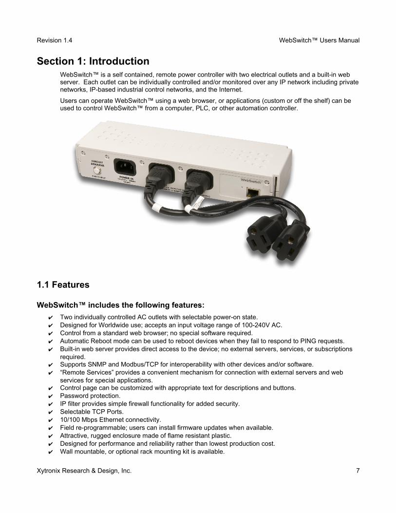
Section 1: IntroductionWebSwitch™ is a self contained, remote power controller with two electrical outlets and a built-in web server. Each outlet can be individually controlled and/or monitored over any IP network including privatenetworks, IP-based industrial control networks, and the Internet.
Users can operate WebSwitch™ using a web browser, or applications (custom or off the shelf) can be used to control WebSwitch™ from a computer, PLC, or other automation controller.
1.1 Features
WebSwitch™ includes the following features:
✔ Two individually controlled AC outlets with selectable power-on state.✔ Designed for Worldwide use; accepts an input voltage range of 100-240V AC. ✔ Control from a standard web browser; no special software required.✔ Automatic Reboot mode can be used to reboot devices when they fail to respond to PING requests.✔ Built-in web server provides direct access to the device; no external servers, services, or subscriptions
required.✔ Supports SNMP and Modbus/TCP for interoperability with other devices and/or software.✔ “Remote Services” provides a convenient mechanism for connection with external servers and web
services for special applications. ✔ Control page can be customized with appropriate text for descriptions and buttons.✔ Password protection.✔ IP filter provides simple firewall functionality for added security.✔ Selectable TCP Ports.✔ 10/100 Mbps Ethernet connectivity.✔ Field re-programmable; users can install firmware updates when available.✔ Attractive, rugged enclosure made of flame resistant plastic.✔ Designed for performance and reliability rather than lowest production cost.✔ Wall mountable, or optional rack mounting kit is available.
Xytronix Research & Design, Inc. 7
Revision 1.4 WebSwitch™ Users Manual
WebSwitch Plus™ (model XRDI-WS3P) also includes the following features:
✔ Temperature and/or humidity sensors can be connected for environmental monitoring. (One temperaturesensor is included, use up to three sensors.)
✔ Dry-contact sensors or switches can be connected for local control of outlets or for monitoring external devices such as access doors (two discrete inputs).
✔ Real-time clock can automatically adjust for daylight savings time and can be synchronized with NTP server.
✔ Event scheduler with yearly calendar; automatically turn outlets on/off or reboot at pre-scheduled times.✔ Email alerts can be configured to send email or text messages when outlets/inputs change or when
temperature goes out of range.✔ Logging; log outlet changes, automatic reboots, high/low temperatures, network traffic, and more.✔ Simple scripts can be written in BASIC for advanced functionality.✔ System log provides detailed diagnostic information.✔ Configure manually or with DHCP.
Note: WebSwitch Plus™ sends out email messages only. Most wireless carriers provide free services to convert email messages to text messages.
1.2 ApplicationsWebSwitch™ can be used with servers, computers, routers, etc., to provide remote control, automatic reboot, or scheduled control of these devices. When configured for automatic reboot, WebSwitch™ will periodically ping a designated IP address and wait for a response. If there is no response to the ping, WebSwitch™ will attempt to bring the device back to normal operation by rebooting the device. There are two common scenarios where the Automatic Reboot feature is useful.
1. WebSwitch™ may be set up to ping a server directly and reboot the server if it fails to respond.
2. WebSwitch™ could be used to reboot a network or communications device if pings to a remote address fail. In this case, WebSwitch controls the power to a network router, switch, radio, modem, etc., but pings a device elsewhere on the network. The assumption is that if the pings cannot reach the remote device, the local communications device may be at fault, so rebooting the device will hopefully restore network communications.
Xytronix Research & Design, Inc. 8

Revision 1.4 WebSwitch™ Users Manual
1.3 WebSwitch™ Models AvailableWebSwitch™ is currently available in two models. The main differences between each model are listed below.
XRDI-WS3 Standard WebSwitch™ with two individually controlled outlets, built-in web server, and automatic reboot functions.
XRDI-WS3P WebSwitch Plus™ includes all features of standard model plus temperature/humidity monitoring (humidity monitoring requires optional humidity sensor), discrete inputs, event scheduling, logging, and additional relay contact protection.
1.3.1 Optional Accessories
Accessory Description Part Number
Temperature Sensor Digital temperature sensor with 12 inch wire leads.(Model XRDI-WS3P only)Note: Leads may be extended
X-DTS-U
Temperature Sensor (Wall Mount)
Digital temperature sensor housed in vented plastic enclosure(Model XRDI-WS3P only)
X-DTS-WM
Temperature/HumiditySensor
Digital temperature and humidity sensor housed in vented plastic enclosure. (Model XRDI-WS3P only)
X-DTHS-WM
Rack Mount Kit Rack mount hardware for mounting WebSwitch™ in a standard 19 inch rack.
X-WS-RMK
Xytronix Research & Design, Inc. 9
Revision 1.4 WebSwitch™ Users Manual
1.4 Connectors & Indicators
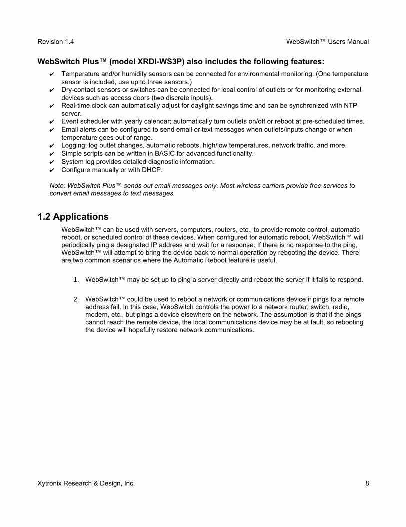
WebSwitch™ has two AC power outlets (IEC 320 C13 female connectors), one AC power input (IEC 320 C14 male connector) and one Ethernet connector. WebSwitch Plus™ also includes a 5-position removable terminal connector to provide connection to discrete inputs and temperature and/or humidity sensors.
WebSwitch™ has five LED indicators. Three LEDs are located on the front panel. One LED is labeled Power and is illuminated green when the module is powered. Two LEDs are labeled Out 1 and Out 2. These are illuminated when the associated outlet is powered. The other two LEDs are located on the Ethernet connector on the back panel. They are labeled LINK and ACT. LINK is illuminated green when the module is properly connected to an Ethernet network and is ready to communicate. Network communications will only occur if this LED is illuminated. The ACT LED flashes amber when activity is detected on the network.
Xytronix Research & Design, Inc. 10
Figure 1.4a- Connectors and Indicators
Revision 1.4 WebSwitch™ Users Manual
1.5 Accessing WebSwitch™
Standard Access Using a Web Browser
WebSwitch™ has a built-in web server and provides simple web pages that can be accessed directly using a standard web browser. This allows users to access the unit with NO SPECIAL SOFTWARE installed on their computer. This is ideal for applications that require a quick, simple solution that does not need to be accessible to more than a few people. This configuration is simple to setup, simple to use, and can be accessed from any computer.
Note: Computers that are not on the local network may only access WebSwitch™ if the local network router is configured to allow access from users beyond the local network (see Appendix C).
Note: This manual assumes standard access. Other methods of accessing WebSwitch™ are explained in Appendix D.
Xytronix Research & Design, Inc. 11

Revision 1.4 WebSwitch™ Users Manual
Section 2: Installation and Setup Installation consists of mounting WebSwitch™, connecting to an IP Network, providing power, and configuring via a web browser.
For WebSwitch Plus™ models, inputs and sensors can be wired to the device using the 5-position terminal connector.
2.1 MountingWebSwitch™ can be placed upon a table top, wall mounted, or rack mounted (with optional rack mount kit). It should be mounted in a clean, dry location where it is protected from the elements. Ventilation is recommend for installations where ambient air temperature is expected to be high.
To mount WebSwitch™ to a wall, use two #8 screws. Attach the screws to the wall horizontally spaced 6 3/8 inches (162 mm) apart. The head of the screws should be about 1/10 inch away from the wall. SeeAppendix I for additional mechanical details.
If WebSwitch™ is to be rack mounted, the rack mounting kit should be purchased separately. Insert the rack mount ears on both sides of WebSwitch™. Secure the rack mount ears by inserting the two pins onthe bottom of the unit. Place WebSwitch™ in the desired location on the rack. Use four rack mount screws to secure WebSwitch™ to the rack.
Xytronix Research & Design, Inc. 12
Figure 2.1a - WebSwitch™ Shown with Optional Rack Mount Ears
Revision 1.4 WebSwitch™ Users Manual
2.2 Connection
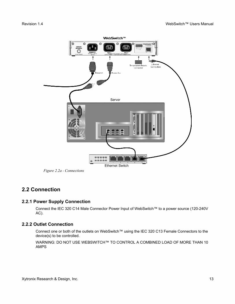
2.2.1 Power Supply Connection
Connect the IEC 320 C14 Male Connector Power Input of WebSwitch™ to a power source (120-240V AC).
2.2.2 Outlet Connection
Connect one or both of the outlets on WebSwitch™ using the IEC 320 C13 Female Connectors to the device(s) to be controlled.
WARNING: DO NOT USE WEBSWITCH™ TO CONTROL A COMBINED LOAD OF MORE THAN 10 AMPS
Xytronix Research & Design, Inc. 13
Figure 2.2a - Connections
Revision 1.4 WebSwitch™ Users Manual
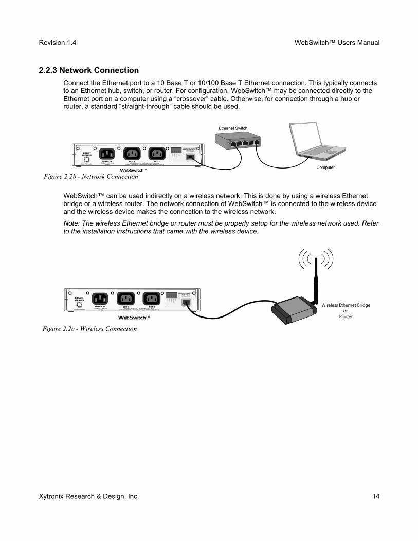
2.2.3 Network Connection
Connect the Ethernet port to a 10 Base T or 10/100 Base T Ethernet connection. This typically connects to an Ethernet hub, switch, or router. For configuration, WebSwitch™ may be connected directly to the Ethernet port on a computer using a “crossover” cable. Otherwise, for connection through a hub or router, a standard “straight-through” cable should be used.
WebSwitch™ can be used indirectly on a wireless network. This is done by using a wireless Ethernet bridge or a wireless router. The network connection of WebSwitch™ is connected to the wireless device and the wireless device makes the connection to the wireless network.
Note: The wireless Ethernet bridge or router must be properly setup for the wireless network used. Referto the installation instructions that came with the wireless device.
Xytronix Research & Design, Inc. 14
Figure 2.2c - Wireless Connection
Figure 2.2b - Network Connection
Revision 1.4 WebSwitch™ Users Manual
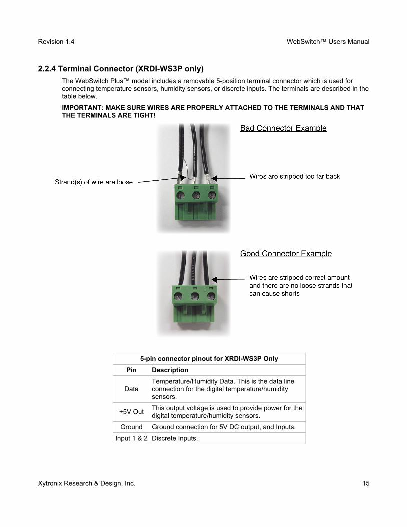
2.2.4 Terminal Connector (XRDI-WS3P only)
The WebSwitch Plus™ model includes a removable 5-position terminal connector which is used for connecting temperature sensors, humidity sensors, or discrete inputs. The terminals are described in thetable below.
IMPORTANT: MAKE SURE WIRES ARE PROPERLY ATTACHED TO THE TERMINALS AND THAT THE TERMINALS ARE TIGHT!
5-pin connector pinout for XRDI-WS3P Only
Pin Description
DataTemperature/Humidity Data. This is the data line connection for the digital temperature/humidity sensors.
+5V OutThis output voltage is used to provide power for thedigital temperature/humidity sensors.
Ground Ground connection for 5V DC output, and Inputs.
Input 1 & 2 Discrete Inputs.
Xytronix Research & Design, Inc. 15
Revision 1.4 WebSwitch™ Users Manual
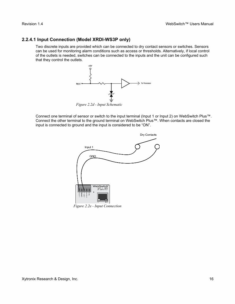
2.2.4.1 Input Connection (Model XRDI-WS3P only)
Two discrete inputs are provided which can be connected to dry contact sensors or switches. Sensors can be used for monitoring alarm conditions such as access or thresholds. Alternatively, if local control of the outlets is needed, switches can be connected to the inputs and the unit can be configured such that they control the outlets.
Connect one terminal of sensor or switch to the input terminal (Input 1 or Input 2) on WebSwitch Plus™. Connect the other terminal to the ground terminal on WebSwitch Plus™. When contacts are closed the input is connected to ground and the input is considered to be “ON”.
Xytronix Research & Design, Inc. 16
Figure 2.2d - Input Schematic
Figure 2.2e - Input Connection
Revision 1.4 WebSwitch™ Users Manual
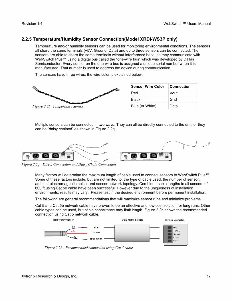
2.2.5 Temperature/Humidity Sensor Connection(Model XRDI-WS3P only)
Temperature and/or humidity sensors can be used for monitoring environmental conditions. The sensorsall share the same terminals (+5V, Ground, Data) and up to three sensors can be connected. The sensors are able to share the same terminals without interference because they communicate with WebSwitch Plus™ using a digital bus called the “one-wire bus” which was developed by Dallas Semiconductor. Every sensor on the one-wire bus is assigned a unique serial number when it is manufactured. That number is used to address the device during communication.
The sensors have three wires; the wire color is explained below.
Sensor Wire Color Connection
Red Vout
Black Gnd
Blue (or White) Data
Multiple sensors can be connected in two ways. They can all be directly connected to the unit, or they can be “daisy chained” as shown in Figure 2.2g.
Many factors will determine the maximum length of cable used to connect sensors to WebSwitch Plus™.Some of these factors include, but are not limited to, the type of cable used, the number of sensor, ambient electromagnetic noise, and sensor network topology. Combined cable lengths to all sensors of 600 ft using Cat 5e cable have been successful. However due to the uniqueness of installation environments, results may vary. Please test in the desired environment before permanent installation.
The following are general recommendations that will maximize sensor runs and minimize problems.
Cat 5 and Cat 5e network cable have proven to be an effective and low-cost solution for long runs. Othercable types can be used, but cable capacitance may limit length. Figure 2.2h shows the recommended connection using Cat 5 network cable.
Xytronix Research & Design, Inc. 17
Figure 2.2f - Temperature Sensor
Figure 2.2g - Direct Connection and Daisy Chain Connection
Figure 2.2h - Recommended connection using Cat 5 cable

Revision 1.4 WebSwitch™ Users Manual
A linear (daisy chain) topology will minimize signal reflections, providing a more reliable connection and longer cable lengths than a star topology.
Appropriate strain relief should be used at WebSwitch™ and other connections may be subjected to vibration, movement, or repeated handling.
Avoid sensor runs adjacent to industrial equipment power cables. These cables have high current spikesthat may induce noise on the sensor signals. Similarly, avoid running sensor cables near any radio transmission antennas or coaxial feedlines.
Protect any electrical connections with appropriate weather shielding.
Due to the broad range of applications and environments were the WebSwitch™ may be employed, installation success on long sensor runs may vary significantly.
Xytronix Research & Design, Inc. 18
Revision 1.4 WebSwitch™ Users Manual
2.3 Establishing Communications for SetupWebSwitch™ is set up using a web browser. The first task is to establish communications between a computer and WebSwitch™ so that the browser-based configuration can begin. To do this, the computerand the WebSwitch™ must be physically connected to the same network and both must have IP addresses on the same network. There are two ways to set up the computer and WebSwitch™ so that they are on the same network. The first (Option 1) is to change the IP address of WebSwitch™ to an address that is on the same network as the computer. The second (Option 2) is to change the IP address of the computer to an address that is on the same network that WebSwitch™ is set to by default.
2.3.1 Option 1: Assign a temporary IP address to WebSwitch™
This option is used to TEMPORARILY assign an IP address to WebSwitch™ without the need to changethe IP address of the configuration computer. Note that WebSwitch™ will only use this IP address as long as power is maintained. Once power is lost and restored, WebSwitch™ will use the IP address assigned in the setup page and not the temporary address assigned here. This means that once communications are established, the desired IP address should be entered into the Network setup tab using the browser.
To assign the temporary IP address...
1. Make sure WebSwitch™ and the configuration computer are connected to the same network.This will not work through routers or gateways.2. Assign the address as follows:
Windows:Open a Command Prompt (select START, then RUN, then type “cmd”).
Note: For Vista, the Command Prompt should be run as administrator (select Start, then type “cmd” and right click on “cmd” and select “Run as administrator”).
Type:arp -s {new IP address} {serial number of WebSwitch™ }
Note: IP address format is xxx.xxx.xxx.xxxSerial number format is ss-ss-ss-ss-ss-ss
For example, to set WebSwitch™ (with serial number 00-0C-C8-01-00-01 ) to 10.10.10.40 the following command would be used:
arp -s 10.10.10.40 00-0c-c8-01-00-01
Next, type:ping -l 102 {new IP address}For example, if the new IP address is 10.10.10.40, the following command would be used:
ping -l 102 10.10.10.40
Linux/Unix:Open a terminal, change to root user (su -, then enter root password).
Xytronix Research & Design, Inc. 19
Revision 1.4 WebSwitch™ Users Manual
Type:arp -s {new IP address} {serial number of WebSwitch™ }
Note: IP address format is xxx.xxx.xxx.xxxSerial number format is ss:ss:ss:ss:ss:ss
For example, to set WebSwitch™ (with serial number 00-0C-C8-01-00-01 ) to 10.10.10.40 the following command would be used:
arp -s 10.10.10.40 00:0c:c8:01:00:01
Next, type:ping -s 102 {new IP address}
For example, if the new IP address is 10.10.10.40, the following command would be used:
ping -s 102 10.10.10.40
Mac OS X:Open a terminal.Note: The terminal is in the “Utilities” directory, which is in the “Applications” directory.
Type:sudo arp -s {new IP address} {serial number of WebSwitch™ }
Note: Administrator password is required.IP address format is xxx.xxx.xxx.xxxSerial number format is ss:ss:ss:ss:ss:ss
For example, to set a WebSwitch™ (with serial number 00-0C-C8-01-00-01 ) to 10.10.10.40 the following command would be used:
sudo arp -s 10.10.10.40 00:0c:c8:01:00:01
Next, type:ping -s 102 {new IP address}For example, if the new IP address is 10.10.10.40, the following command would be used:
ping -s 102 10.10.10.40
2.3.2 Option 2: Assign a temporary IP address to configuration computer
If the first option above is not used, you can use this option to communicate with WebSwitch™. By default, WebSwitch™ comes from the factory with an IP address of 192.168.1.2. Communications with WebSwitch™ may be established by assigning an IP address to the configuration computer that is on the same network as WebSwitch™ (for example, the configuration computer could be assigned to 192.168.1.50)
The following example is for those running the Windows operating system:
Xytronix Research & Design, Inc. 20
Revision 1.4 WebSwitch™ Users Manual
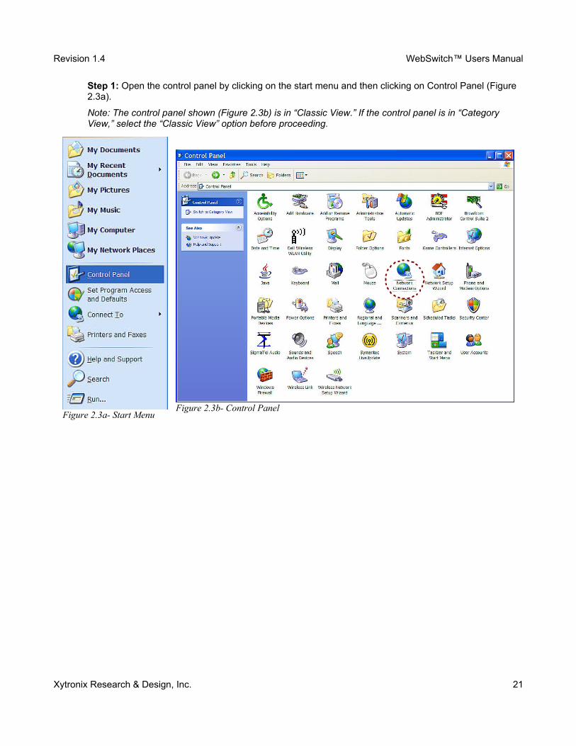
Step 1: Open the control panel by clicking on the start menu and then clicking on Control Panel (Figure 2.3a).
Note: The control panel shown (Figure 2.3b) is in “Classic View.” If the control panel is in “Category View,” select the “Classic View” option before proceeding.
Xytronix Research & Design, Inc. 21
Figure 2.3a- Start MenuFigure 2.3b- Control Panel
Revision 1.4 WebSwitch™ Users Manual
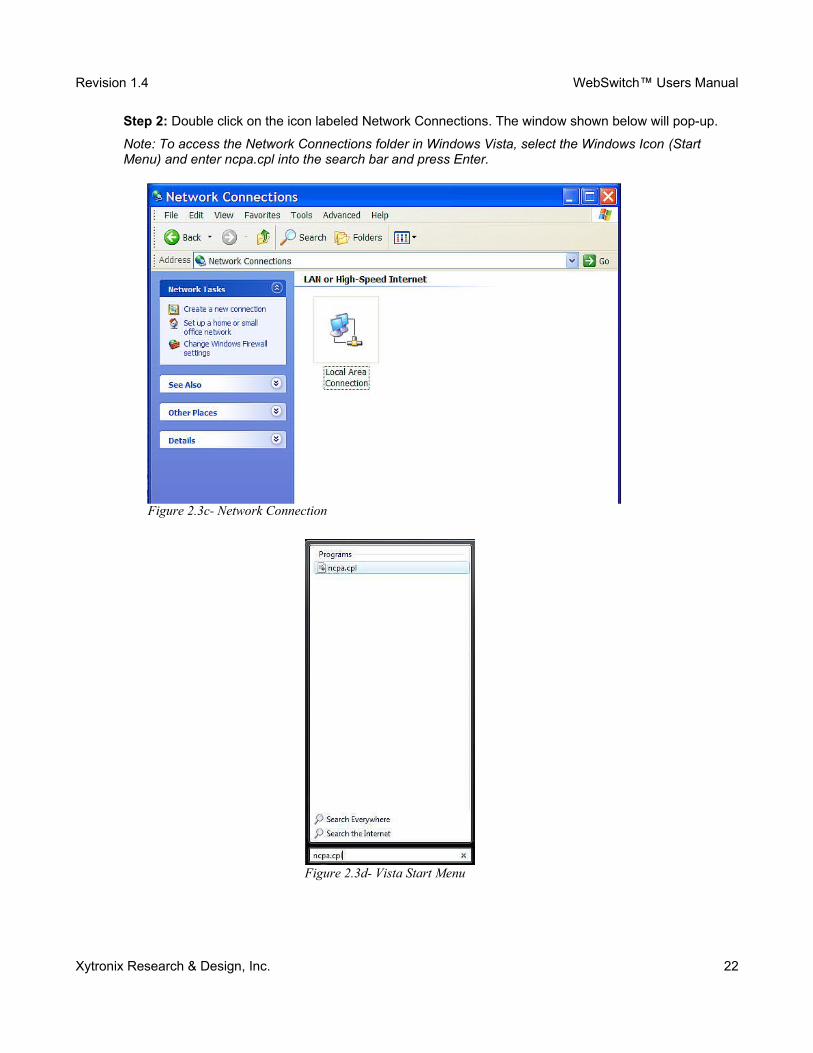
Step 2: Double click on the icon labeled Network Connections. The window shown below will pop-up.
Note: To access the Network Connections folder in Windows Vista, select the Windows Icon (Start Menu) and enter ncpa.cpl into the search bar and press Enter.
Xytronix Research & Design, Inc. 22
Figure 2.3c- Network Connection
Figure 2.3d- Vista Start Menu
Revision 1.4 WebSwitch™ Users Manual
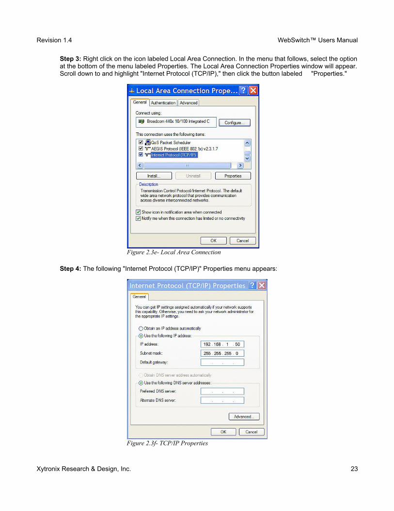
Step 3: Right click on the icon labeled Local Area Connection. In the menu that follows, select the optionat the bottom of the menu labeled Properties. The Local Area Connection Properties window will appear.Scroll down to and highlight "Internet Protocol (TCP/IP)," then click the button labeled "Properties."
Step 4: The following "Internet Protocol (TCP/IP)" Properties menu appears:
Xytronix Research & Design, Inc. 23
Figure 2.3e- Local Area Connection
Figure 2.3f- TCP/IP Properties
Revision 1.4 WebSwitch™ Users Manual
Step 5: Select the radio button labeled "Use the following IP address" and type in the IP address 192.168.1.50. Type in a subnet mask of 255.255.255.0. No need to change the default gateway field. Click OK to accept the new settings.
Note: If “Use the following IP address” is already selected, the values need to be recorded, then re-entered once the IP address of WebSwitch™ is successfully changed.
2.3.3 Open Configuration Web Page
Once the network is set up, open the setup page as described in section 2.4. If the setup pages are not accessible, verify that WebSwitch™ is powered on and that the LINK light is illuminated. Check all network connections and settings. Another way to check communications is to ping WebSwitch™ (from the command prompt by typing ping {WebSwitch IP address} ).
Xytronix Research & Design, Inc. 24
Revision 1.4 WebSwitch™ Users Manual
2.4 WebSwitch™ Setup Pages WebSwitch™ is configured using a web browser. To access the setup pages, enter the following URL in the address bar of a web browser:
http://ipaddress/setup.html
For example, using the default IP address, enter:
http://192.168.1.2/setup.html
After the page is requested, a password prompt will appear. Enter the username and password.
Note: The default username is admin and the default password is webswitch (password is case sensitive).
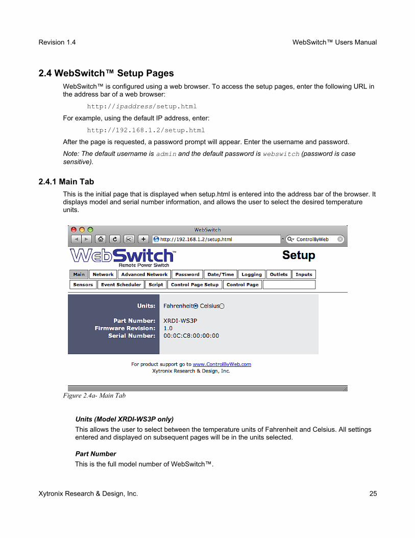
2.4.1 Main Tab
This is the initial page that is displayed when setup.html is entered into the address bar of the browser. Itdisplays model and serial number information, and allows the user to select the desired temperature units.
Units (Model XRDI-WS3P only)
This allows the user to select between the temperature units of Fahrenheit and Celsius. All settings entered and displayed on subsequent pages will be in the units selected.
Part Number
This is the full model number of WebSwitch™.
Xytronix Research & Design, Inc. 25
Figure 2.4a- Main Tab

Revision 1.4 WebSwitch™ Users Manual
Firmware Revision
This is the current product revision of the unit's firmware.
Serial Number
This is the serial number of this unit. The serial number is also the MAC address of the unit.
Xytronix Research & Design, Inc. 26
Revision 1.4 WebSwitch™ Users Manual
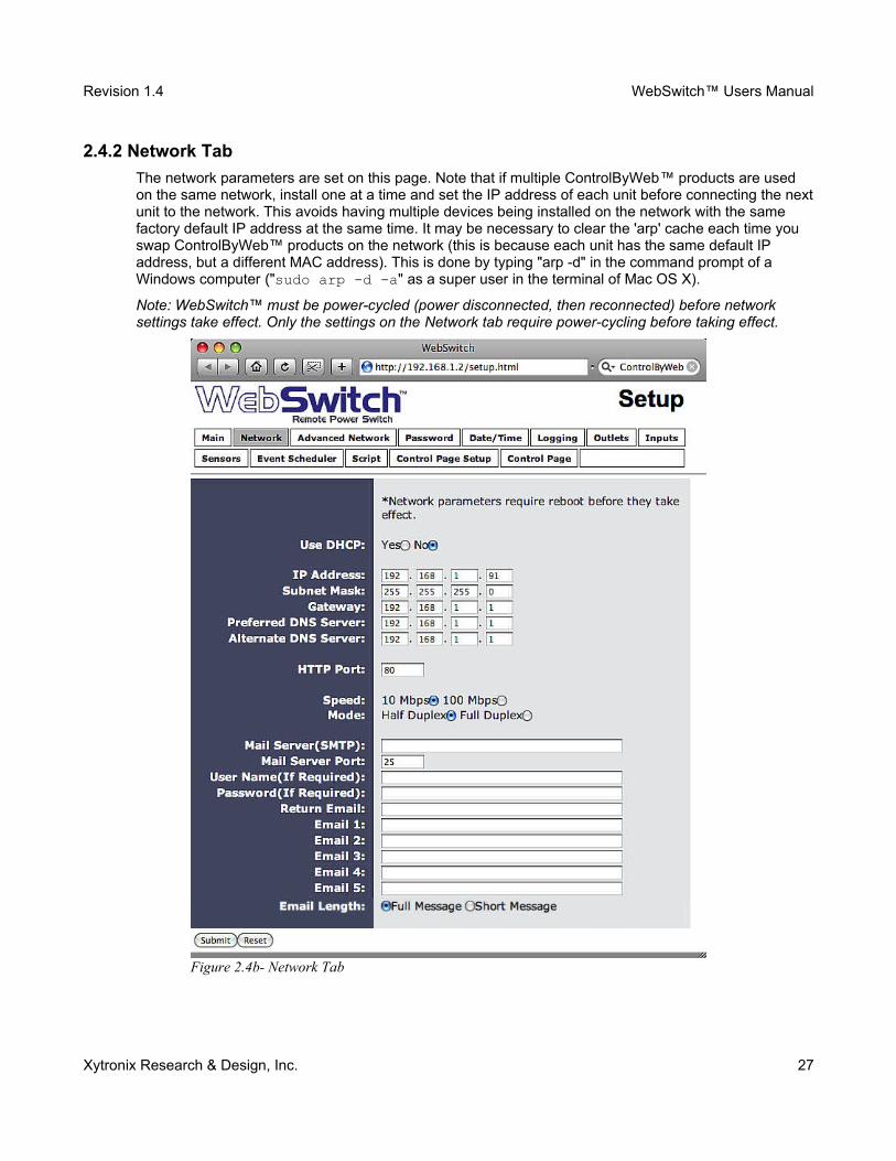
2.4.2 Network Tab
The network parameters are set on this page. Note that if multiple ControlByWeb™ products are used on the same network, install one at a time and set the IP address of each unit before connecting the nextunit to the network. This avoids having multiple devices being installed on the network with the same factory default IP address at the same time. It may be necessary to clear the 'arp' cache each time you swap ControlByWeb™ products on the network (this is because each unit has the same default IP address, but a different MAC address). This is done by typing "arp -d" in the command prompt of a Windows computer ("sudo arp -d -a" as a super user in the terminal of Mac OS X).
Note: WebSwitch™ must be power-cycled (power disconnected, then reconnected) before network settings take effect. Only the settings on the Network tab require power-cycling before taking effect.
Xytronix Research & Design, Inc. 27
Figure 2.4b- Network Tab
Revision 1.4 WebSwitch™ Users Manual
Use DHCP (model XRDI-WS3P only)
This option allows DHCP to be enabled or disabled. If this option is set to Yes, WebSwitch™ will wait for an IP address from a DHCP server each time it is powered. The default setting is No (this is recommended for most installations). If DHCP is set to Yes, the Network page must be submitted and WebSwitch™ must be rebooted before an IP address will be assigned. Once the WebSwitch™ is assigned an IP address by the DHCP, the new IP address can be found through the clients list kept by the DHCP server. For most instances, this is found on the local gateway or router.
MTU Setting
To change the MTU, manually enter the advSetup.html (case sensitive) page into the address bar. (http://192.168.1.2/advSetup.html). This new setup page will have a text box that will allow the MTU to be changed. The valid range is 256 to 1476 bytes. MTU is a network parameter that stands for Maximum Transmission Unit. This defines the max size, in bytes, of the TCP packets sent out from the device. This normally can be left alone, but there are some circumstances where it might be beneficial to change it. One of these circumstances is when the device is to be used over a VPN (virtual private network). VPN's add extra information to TCP packets, if the new packets are too big to physically travel across the network (greater than about 1500 bytes) then the packets will be split up. This causes problems for some firewalls and those firewalls will just discard the packets. To fix this, the MTU can be adjusted until the TCP packets do not get split up.
Brief notes about DHCP
All devices on an IP network require an IP address. This is a unique address that identifies each device on the network. DHCP (Dynamic Host Control Protocol) is a mechanism that automatically assigns an IP address to a computer (or other devices) when it is connected to a network. This eliminates the need to manually enter the IP address. When a computer is connected to the network, another device on the network called a DHCP server detects the presence of the computerand dynamically assigns the IP address to that computer. On many small networks, the DHCP server is built into the router.
DHCP works well for "client" devices such as computers, but is not ideal for servers. This is becauseservers usually don't initiate communications with other devices, but rather they wait for a request from "clients." To make this request, the client must know the IP address of the server. If a server gets its IP address dynamically, the IP address may not always be the same so client devices may not be able to find the server. For this reason, servers usually use an IP address that is fixed and does not change. The WebSwitch™ is a server and manual IP address assignment is usually recommended.
IP Address
Enter the IP address for WebSwitch™ in this field. The IP address is specific to the network where WebSwitch™ will be installed, and must be obtained from the network administrator. For more information on IP addresses and remotely accessing WebSwitch™ over the Internet, see Appendix C: Remote Access. The default setting for this field is 192.168.1.2.
Subnet Mask
The subnet mask defines the size of the local network. This must be obtained from the network administrator. For additional information about sub-netting and IP networking, many tutorials are available on the Internet. The default setting for this field is 255.255.255.0.
Gateway
This specifies the IP address of the gateway router. This must be obtained from the network administrator. The default setting for this field is 192.168.1.1.
Xytronix Research & Design, Inc. 28
Revision 1.4 WebSwitch™ Users Manual
Preferred DNS Server
The IP address of the Primary DNS server is specified here. When DNS services are required, this is the address that will be used. The default setting for this field is 192.168.1.1.
Note: This field is only required when the following options are used
━ Remote Services (when server is specified by name and not IP address).━ Sync time clock with remote NTP server (when server name is specified by name and not IP
address).━ Mail Server (when server name is specified by name and not IP address).
Alternate DNS Server
This field is used to specify the IP address of a Secondary DNS server. This is used when the WebSwitch™ requires DNS services and the preferred DNS server is not available. The default setting for this field is 192.168.1.1.
HTTP Port
The TCP port used for HTTP communications (web browser, xml, get commands) with WebSwitch™ is specified here. It is recommended that the port not be changed without an understanding of TCP/IP and ports. For more information on TCP ports and IP addressing see Appendix C: Remote Access. The default setting for this field is 80, which is the standard HTTP port.
Speed
This option sets the data rate (clock rate) of the Ethernet port. Either 10Mbps or 100Mbps can be selected. The 100Mbps option offers faster communications but the amount of data to and from WebSwitch™ is so small that users will not likely notice much (if any) difference. When WebSwitch™ is set to 10Mbps, it draws less power and runs a little cooler which translates into a longer product life. IT IS RECOMMENDED THAT THIS SETTING BE LEFT AT 10Mbps UNLESS THE USER HAS A SPECIFIC REASON TO USE 100Mbps. The default setting for this field is 10Mbps.
Mode
This option allows the Ethernet port to be set to Half Duplex or Full Duplex. Legacy Ethernet operates in Half Duplex mode which means that devices can either send data or receive data, but not both at the same time. Full Duplex means that devices can send and receive data at the same time. The default setting for this field is Half Duplex.
The remaining fields on the Network tab are required only if WebSwitch™ is configured to send email messages when alarm conditions occur (Model XRDI-WS3P only) .
Mail Server (SMTP)
The name of the SMTP (Simple Network Transport Protocol) mail server (for example mail.example.com) or the IP address of the mail server (for example 192.10.10.10) should be entered in this field. There is no default setting for this field
Note: if the server name is entered and not the IP address, the address of a DNS server will be required.
Mail Server Port
This field is used to specify the SMTP Mail Server Port. The default setting is 25, which is the standard SMTP port.
Xytronix Research & Design, Inc. 29
Revision 1.4 WebSwitch™ Users Manual
User Name (If Required)
If the SMTP mail server requires authentication, the user name must be entered here. There is no default setting for this field.
Password (If Required)
If the SMTP mail server requires authentication, the password must be entered here. There is no default setting for this field.
Return Email
WebSwitch™ will not receive email messages, but when WebSwitch™ sends email messages, it must include a return email address. This field is used to specify the return email address. Note that although WebSwitch™ will send email messages with any email address specified in this field, someemail filters (spam filters) will not allow messages through that include an invalid email address. There is no default setting for this field.
Email 1 to Email 5
Enter the email addresses of up to five recipients for alarm messages in these fields. There are no default settings for these fields.
Email Length
Choose either “full” or “short” email lengths. When “full” is selected, all visible fields in the control page will be included as a description of what triggered the email to be sent out; however if “short” isselected, the email content will only be a brief description of what triggered the email to be sent out.
Remote Reboot
To cause the device to reboot, the following command can be entered into the address bar of the browser: http://192.168.1.2/networkSetup.srv?rbt=1 The username and password will be requested before the reboot will occur, so that only administrators of the device can cause the reboot.
Xytronix Research & Design, Inc. 30
Revision 1.4 WebSwitch™ Users Manual
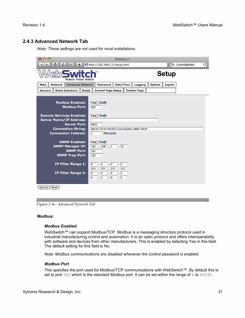
2.4.3 Advanced Network Tab
Note: These settings are not used for most installations.
Modbus:
Modbus Enabled
WebSwitch™ can support Modbus/TCP. Modbus is a messaging structure protocol used in industrial manufacturing control and automation. It is an open protocol and offers interoperability with software and devices from other manufacturers. This is enabled by selecting Yes in this field. The default setting for this field is No.
Note: Modbus communications are disabled whenever the control password is enabled.
Modbus Port
This specifies the port used for Modbus/TCP communications with WebSwitch™. By default this is set to port 502 which is the standard Modbus port. It can be set within the range of 0 to 65535.
Xytronix Research & Design, Inc. 31
Figure 2.4c- Advanced Network Tab
Revision 1.4 WebSwitch™ Users Manual
Remote Services
Remote Services initiates an outgoing connection to a server at a remote location. This can be used, for example, in an environment where a web server on the Internet provides a custom user interface and users access WebSwitch™ through the web server rather than communicating directly with WebSwitch™. This is sometimes referred to as “web services”. As mentioned elsewhere in this users manual, using an external web server allows users to access one or many WebSwitch™ units (or other ControlByWeb™ products) through a custom web page. This has the benefits of being able to combine multiple devices seamlessly into a single web page, and it allows programmers to create powerful, custom web pages using the web programming languages of their choice.
Using the Remote Services configuration so that WebSwitch™ units initiate the connection to the external web server (rather than having the web server initiate communications to WebSwitch™ units) has two main benefits. First, the web server does not need to know the IP address of WebSwitch™. Thismeans that WebSwitch™ can get its IP address dynamically from a DHCP server which simplifies the installation. Second, since the connection from WebSwitch™ is outgoing, rather than incoming, the local router on the network where WebSwitch™ resides doesn't need to be configured to forward sockets. This also has the benefit of simplifying the installation. In addition, since the router configuration is not modified, the risk of compromising security on the local network is eliminated. For more information about the Remote Services see Appendix D: External Server and Remote Services.
Remote Services Enabled
This option enables or disables Remote Services. If Yes is selected, Remote Services will be enabled as soon as the submit button is pressed and WebSwitch™ will immediately attempt to makea connection with the remote server (power cycle not required). Once a connection is established, the connection will remain until it is disconnected by the remote server. Proper connection with the remote server can be verified by viewing the system status log file (see Appendix E: Log Files). The default setting for this field is No. Most users should leave this setting at its default.
Server Name/IP Address
Specify the name or IP address of the Remote Services server here. If the IP address is specified, enter it in this format aaa.bbb.ccc.ddd. For numbers that are less than 100, preceding zeros should not be included (for example, enter 80 rather than 080). This field can be up to 40 characters long and has no default setting.
Server Port
Enter the TCP port used for the Remote Services server. This can be set within the range of 0-65535. The default setting for this field is 8000.
Connection String
This text is sent to the Remote Services server when the connection is established. This string should include any information required by the server at connection. For example, it may include an ID number, customer number, password, etc. The format is entirely dependent upon the server requirements. This field can be up to 80 characters long. Default text is provided only as an exampleplaceholder. The default text is [<serialAddress>]:ControlByWeb,XRDI-WS3(P).
Connection Interval
This field specifies the periodic interval in which WebSwitch™ attempts to connect to the remote server, or if WebSwitch™ is already connected, it is the interval in which WebSwitch™ sends the connection string. This field can be set within the range of 1 to 34452 minutes. The default setting for this field is 1 minute.
Xytronix Research & Design, Inc. 32
Revision 1.4 WebSwitch™ Users Manual
SNMP
Simple Network Management Protocol (SNMP) is used to manage and administer network devices. WebSwitch™ supports SNMP V1.0 and can be configured here. Using SNMP, the input and power outlet states of WebSwitch™ can be read as well as some basic information about the device. See Appendix F: SNMP Requests for information about how to request information from WebSwitch™ using an SNMP manager, as well as where to find MIB files for WebSwitch™.
Note: The read and write community strings used for SNMP are actually the control password found on the Password setup tab (see Section 2.4.4). If the control password is disabled, then WebSwitch™ does not check for the community string when issued a Get or Get Next request from the SNMP manager.
SNMP Enabled
When this option is set to Yes, WebSwitch™ will support SNMP. The default setting for this option isNo.
SNMP Manager IP
When SNMP is used, this field is used to specify the IP address of the SNMP manager. The default setting for this field is 192.168.1.25.
SNMP Port
When SNMP is used, this field is used to specify the SNMP port that WebSwitch™ listens on. The default setting for this field is 161.
SNMP Trap Port
When SNMP is used, this field is used to specify the SNMP Trap port of the SNMP manager. The default setting for this field is 162.
IP Filter Range 1 and IP Filter Range 2
For additional security, WebSwitch™ has a simple built-in firewall. If desired, WebSwitch™ can be configured to only allow access to client devices (computers, servers, other ControlByWeb™ devices, etc) with certain IP addresses. Two IP address ranges are provided and only client devices with addresses that fall within those two ranges will be allowed to communicate. Devices with IP addresses that fall outside of those ranges will not receive any response from WebSwitch™.
Example:
To allow access from any device (this is the default setting):
IP Filter Range 1: 0.0.0.0255.255.255.255
IP Filter Range 2: 0.0.0.00.0.0.0
To limit access to only one device (address 192.168.1.33):
IP Filter Range 1: 192.168.1.33192.168.1.33
IP Filter Range 2: 0.0.0.00.0.0.0
Xytronix Research & Design, Inc. 33

Revision 1.4 WebSwitch™ Users Manual
To limit access to only devices on the local network and one device on the internet (address 10.143.100.32):
IP Filter Range 1: 192.168.1.0192.168.1.255
IP Filter Range 2: 10.143.100.3210.143.100.32
Note: The address specified for the Remote Services server (if applicable) is automatically allowed through the firewall no matter how this is set.
Xytronix Research & Design, Inc. 34
Revision 1.4 WebSwitch™ Users Manual
2.4.4 Password Tab
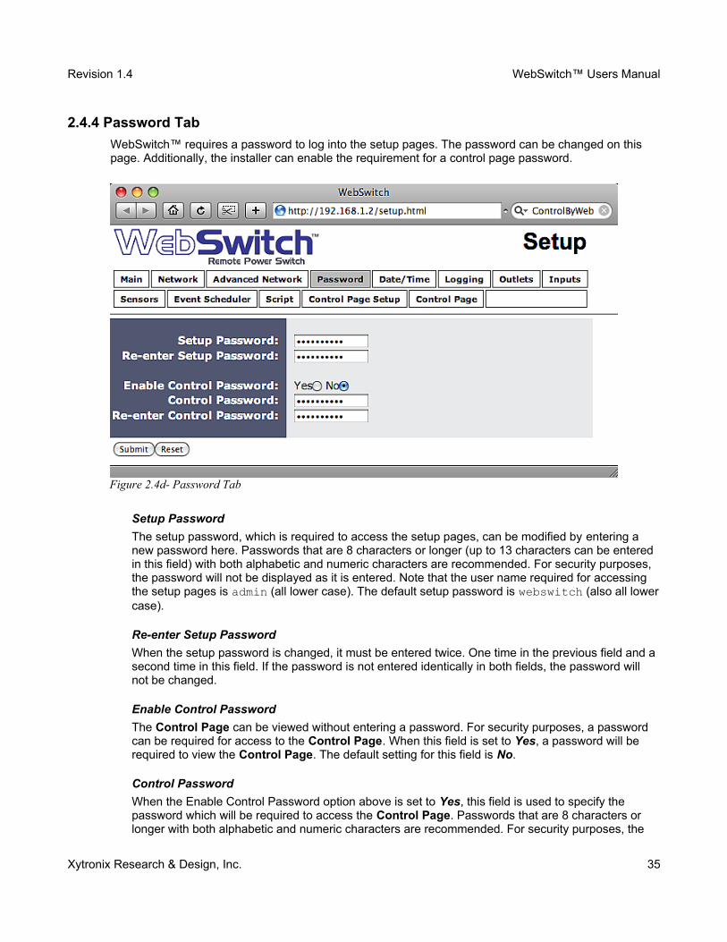
WebSwitch™ requires a password to log into the setup pages. The password can be changed on this page. Additionally, the installer can enable the requirement for a control page password.
Setup Password
The setup password, which is required to access the setup pages, can be modified by entering a new password here. Passwords that are 8 characters or longer (up to 13 characters can be entered in this field) with both alphabetic and numeric characters are recommended. For security purposes, the password will not be displayed as it is entered. Note that the user name required for accessing the setup pages is admin (all lower case). The default setup password is webswitch (also all lowercase).
Re-enter Setup Password
When the setup password is changed, it must be entered twice. One time in the previous field and a second time in this field. If the password is not entered identically in both fields, the password will not be changed.
Enable Control Password
The Control Page can be viewed without entering a password. For security purposes, a password can be required for access to the Control Page. When this field is set to Yes, a password will be required to view the Control Page. The default setting for this field is No.
Control Password
When the Enable Control Password option above is set to Yes, this field is used to specify the password which will be required to access the Control Page. Passwords that are 8 characters or longer with both alphabetic and numeric characters are recommended. For security purposes, the
Xytronix Research & Design, Inc. 35
Figure 2.4d- Password Tab

Revision 1.4 WebSwitch™ Users Manual
password will not be displayed as it is entered. Note that WebSwitch™ requires a password, but does not require a user name to access the Control Page. However, some browsers require that a user name be entered. In this instance enter none as the user name. The default control password is webswitch.
Re-enter Control Password
When the control password is changed, it must be entered twice. One time in the previous field, and a second time in this field. If the password is not entered identically in both fields, the password will not be changed.
Xytronix Research & Design, Inc. 36
Revision 1.4 WebSwitch™ Users Manual
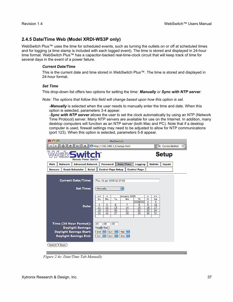
2.4.5 Date/Time Web (Model XRDI-WS3P only)
WebSwitch Plus™ uses the time for scheduled events, such as turning the outlets on or off at scheduled times and for logging (a time stamp is included with each logged event). The time is stored and displayed in 24-hour time format. WebSwitch Plus™ has a capacitor-backed real-time-clock circuit that will keep track of time for several days in the event of a power failure.
Current Date/Time
This is the current date and time stored in WebSwitch Plus™. The time is stored and displayed in 24-hour format.
Set Time
This drop-down list offers two options for setting the time: Manually or Sync with NTP server.
Note: The options that follow this field will change based upon how this option is set.
-Manually is selected when the user needs to manually enter the time and date. When this option is selected, parameters 3-4 appear.-Sync with NTP server allows the user to set the clock automatically by using an NTP (NetworkTime Protocol) server. Many NTP servers are available for use on the Internet. In addition, manydesktop computers will function as an NTP server (both Mac and PC). Note that if a desktop computer is used, firewall settings may need to be adjusted to allow for NTP communications (port 123). When this option is selected, parameters 5-8 appear.
Xytronix Research & Design, Inc. 37
Figure 2.4e- Date/Time Tab-Manually

Revision 1.4 WebSwitch™ Users Manual
The following parameters are available when the Set Time is set to Manually:
Date
This field is used to enter the current date. The date is entered by first selecting the correct month and year by using the left and right arrows at the top of the calender. The single arrows (< and >) change the month and the double arrows (<< and >>) change the year. Once the current month and year are displayed, the date should be entered by moving the mouse pointer over the correct day and clicking the (left) mouse button to highlight that date.
Time (24 Hour Format)
Enter the time as HH:MM:SS. (HH represents hours in 24-hour format [00-23], MM represents minutes [00-59], SS represents seconds [00-59].)
The following parameters (5-8) are available when Set Time is set to Sync with NTP server:
Server Name/IP Address
This field is used to specify the name or IP address of the NTP server. If a name is specified, a working DNS server address must be entered into the Network settings. If the IP address is specified, it should be entered in the following format aaa.bbb.ccc.ddd where each of the letters represents a number between 0 and 255. This field can be up to 40 characters. There is no default value for this field.
Xytronix Research & Design, Inc. 38
Figure 2.4f- Date/Time Tab-NTP Server Synchronization
Revision 1.4 WebSwitch™ Users Manual
Sync With Server
This option allows the user to specify how often the WebSwitch Plus™ time will be synchronized with the time server. When the submit button on this page is pressed, the WebSwitch Plus™ will immediately synchronize with the time server. If Daily, Weekly, or Monthly options are selected, WebSwitch Plus™ will thereafter re-synchronize with the time server at the period interval specified starting at 12:00 AM (00:00). The exact time the NTP Request occurs is 12:00 AM (00:00) plus the minute equivalent of the last two digits in the models Serial Number. For example, if the last two digits in the model's serial number were -09, the NTP Request will occur 9 minutes after 12:00 AM. The default value of this setting is Once (the unit will immediately sync with the NTP server, but will not automatically sync again).
Sync on Power Up
When this option is set to Yes, WebSwitch Plus™ will be synchronized with the time server each time it is powered. Note that if it is expected that WebSwitch Plus™ will lose power on a frequent basis, it may be beneficial to set this option to No; some time servers are configured to dis-allow access from client devices that excessively request their services. The default value of this setting isNo.
UTC Offset
Time servers return the current time in Universal Time (GMT). It is common for many servers and data loggers to use GMT as their official time, even when they are not located within the GMT time zone. The default value for this field is -7 (Mountain Standard Time). For convenience, the time can be converted to local standard time by entering the offset here. This manual cannot include the UTCOffset for all parts of the world, but the offset for GMT time and the four major US Time zones are listed here.
━ GMT Time: 0━ Eastern Standard Time: -5━ Central Standard Time: -6━ Mountain Standard Time: -7━ Pacific Standard Time: -8
Daylight Savings
In many parts of the United States and in some other countries, the time is shifted forward by one hour during the summer months. This is an effort to conserve energy by making the daylight last longer into the evening hours. If this option is set to Yes, the time on WebSwitch Plus™ will automatically be shifted forward by one hour between the hours of 12:00 AM – 5:00 PM on the Daylight Savings Start date set below, and it will shift back to standard time between the hours of 12:00 AM – 5:00 PM on the Daylight Savings End date set below. The time change is made at a random time within the previously mentioned, five-hour time frame, in order to prevent several different devices from simultaneously requesting a time and overwhelming the NTP server. The default setting is Yes.
Please note that by enabling the daylight savings time adjustment, scheduled events will be adjusted for the new time. Also note that logged data includes a time stamp based upon the current time in the device so it is possible to duplicate log times in the spring and miss log times in the fall. To avoid confusion, many servers and data loggers are set to remain on GMT time and do not shift for daylight savings.
Xytronix Research & Design, Inc. 39

Revision 1.4 WebSwitch™ Users Manual
Daylight Savings Start
This is the date that daylight savings will start. Note that on this date, between the hours of 12:00 AM – 5:00 PM, the current time will be shifted forward by one hour (i.e. the time will jump from 12:02AM [00:02] to 1:02 AM [01:02]). By default this is set to the 2nd Sunday in March which is the date used in the United States.
Daylight Savings End
This is the date that daylight savings will end. Note that on this date, between the hours of 12:00 AM– 5:00 PM, the current time will be shifted backward by one hour (i.e. the time will jump from 12:02 AM [00:02] to 11:02 PM [23:02] the day before). By default this is set to the 1st Sunday in Novemberwhich is the date used in the United States.
Xytronix Research & Design, Inc. 40
Revision 1.4 WebSwitch™ Users Manual
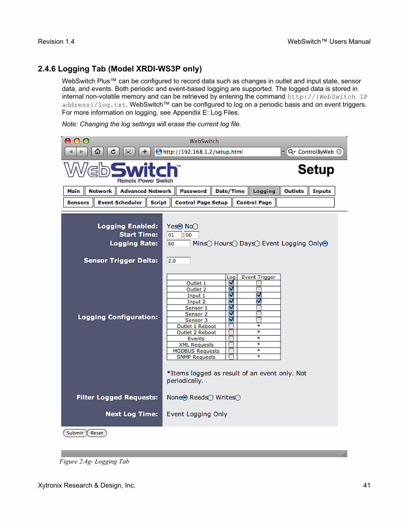
2.4.6 Logging Tab (Model XRDI-WS3P only)
WebSwitch Plus™ can be configured to record data such as changes in outlet and input state, sensor data, and events. Both periodic and event-based logging are supported. The logged data is stored in internal non-volatile memory and can be retrieved by entering the command http://{WebSwitch IPaddress}/log.txt. WebSwitch™ can be configured to log on a periodic basis and on event triggers. For more information on logging, see Appendix E: Log Files.
Note: Changing the log settings will erase the current log file.
Xytronix Research & Design, Inc. 41
Figure 2.4g- Logging Tab

Revision 1.4 WebSwitch™ Users Manual
Logging Enabled
When this option is set to Yes, WebSwitch Plus™ will record data as configured on this page.
Note: this option controls data logging but not system logging. System logging is always enabled. The default setting for this option is No.
Start Time
If a logging interval is specified (periodic logging rather than event logging), logging will occur relative to this start time. For example, if the start time is 01:00 and the logging rate is 6 hours, logging will occur at 01:00, 07:00, 13:00, and 19:00. Start time is specified in 24-hour time format. The default setting for this field is 01:00.
Logging Rate
This field is used to specify the time period of logging. A numerical value is entered into the text field, and the unit of time is selected using the adjacent radio buttons. The range of values in this field is 1-20864. Time units are Minutes, Hours, and Days. Periodic logging can be disabled by selecting the Event Logging Only radio button.
Sensor Trigger Delta
WebSwitch Plus™ can be configured to log data when the temperature/humidity measured by a sensor changes by the amount specified in this field. This can be set from 1.0 to 24.0 degrees in 0.1 increments. The default setting for this field is 2.0 degrees.
Logging Configuration
This table is used to select which outlets, inputs, and sensors get logged and which events trigger the logging. The first column in the table identifies the outlets, inputs, sensors, etc. that can be logged or cause logging events. The second column is used to specify what gets logged. The third column is used to specify which events can cause a log entry to be created.
When outlets are selected as an event trigger, logging will occur whenever the selected outlet is turned on or off. When inputs are selected as an event trigger, logging will occur whenever the input state changes. When sensors are selected as an event trigger, logging will occur whenever the temperature/humidity changes by a set amount. When outlet reboots are selected as an event trigger, logging will occur whenever the selected outlet automatically reboots.
The following Log/Event trigger options are available:
Outlet 1Outlet 2Input 1Input 2Sensor 1Sensor 2Sensor 3EventsOutlet 1 RebootOutlet 2 RebootXML RequestsModbus RequestsSNMP Requests
Xytronix Research & Design, Inc. 42
Revision 1.4 WebSwitch™ Users Manual
Filter Logged Requests
When logging is enabled for XML Requests, Modbus Requests, or SNMP Requests, the user can filter out Reads (such as reading the outlet or input state via an XML request) or Writes (such as changing the outlet state via an XML command).
On the Control Page Setup tab, the user can specify the refresh rate of the Control Page. Each time the page is refreshed, an XML request is sent and logged as a Read. Since the default refresh rate is 3 seconds, the log file can get cluttered by many XML request logs. By selecting Reads, those XML requests will not be shown in the log. Likewise, by selecting Writes, any log created by changing the state of the relay will not be shown in the log file. Default selection is None.
Note: When XML Requests are setup to be logged, the IP address from which the Read or Write is generated is logged, as well as if it was a Read request (R) or Write request (W). See Appendix E: Log Files for additional information.
Next Log Time
This field displays the next periodic log time. If logging is disabled, the next log time will indicate "Disabled." If logging is enabled, but periodic logging is disabled (by selecting Event Logging Only)the next log time will indicate "Event Logging Only."
Note: This information is updated only when the page is refreshed.
Xytronix Research & Design, Inc. 43
Revision 1.4 WebSwitch™ Users Manual
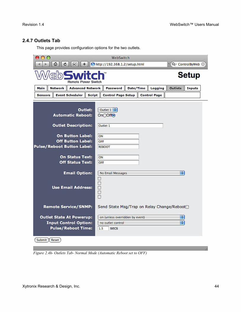
2.4.7 Outlets Tab
This page provides configuration options for the two outlets.
Xytronix Research & Design, Inc. 44
Figure 2.4h- Outlets Tab- Normal Mode (Automatic Reboot set to OFF)
Revision 1.4 WebSwitch™ Users Manual
Outlet
This drop down menu is used to select the outlet for which the options below will apply.
-Outlet 1 or Outlet 2: Selects the built-in outlets.
Automatic Reboot
When this option is set to On, WebSwitch™ will operate in Automatic Reboot mode. In Automatic Reboot mode, WebSwitch™ is configured to periodically confirm that another device (such as a server, computer, router, etc.) is working by sending ping requests to the device. WebSwitch™ expects a response after each ping. If a pre-set number of ping requests fail, it is assumed that the device is not functioning properly. WebSwitch™ will attempt to restore the device to normal operation by rebooting the device. In Automatic Reboot mode, users still have the ability to manually reboot the device from a remote location over the network. The default setting for this field is Off.
When automatic reboot is set to Off, WebSwitch™ will operate in Normal mode. In Normal mode, WebSwitch™ will only change the state of the outlets when commanded by a user.
Outlet Description
This text field is used to describe the function of the selected outlet. The text appears to the left of the corresponding outlet status on the Control Page, and in the email message when email alerts are enabled. Up to 24 characters may be entered in this field. The default text is Outlet #.
On Button Label
The text entered in this field appears in the 'On' button for the corresponding outlet on the Control Page. Up to 15 characters may be entered in this field. The default text is ON.
Off Button Label
The text entered in this field appears in the 'Off' button for the corresponding outlet on the Control Page. Up to 15 characters may be entered in this field. The default text is OFF.
Pulse/Reboot Button Label
The text entered in this field appears in the 'Pulse' button for the corresponding outlet on the Control Page. Up to 15 characters may be entered in this field. The default text is REBOOT.
On Status Text
The text in this field specifies the text that will be displayed in the status field in the Control Page andin email messages when the corresponding outlet is on. Up to 15 characters may be entered in this field. The default text is ON.
Off Status Text
The text in this field specifies the text that will be displayed in the status field in the Control Page andin email messages when the corresponding outlet is off. Up to 15 characters may be entered in this field. The default text is OFF.
Xytronix Research & Design, Inc. 45
Revision 1.4 WebSwitch™ Users Manual
Email Option (Model XRDI-WS3P only)
Simple email messages can be sent when outlets are turned on or off. This parameter is used to specify what conditions, if any, will cause email messages to be sent. Note that email notification willwork only if the email settings are correctly set up in the Network setup page. The following options are available:
-No Email Messages: No email notifications will be sent when outlet changes.-Send Email when outlet on: Email notifications will be sent when outlet state changes to on.-Send Email when outlet off: Email notifications will be sent when outlet state changes to off.-Send Email when outlet changes state: Email notifications will be sent when outlet changes state to on or off.-Send Email on pulse/reboot: Email notifications will be sent when the outlet is pulsed or automatically rebooted.
Note: The default setting for this field is No Email Messages.
Use Email Address (Model XRDI-WS3P only)
If email messages are to be sent out when outlets change state, these check boxes specify to whichemail addresses the message will be sent. Email addresses specified on the Network setup tab will be displayed next to each check box. By default, no boxes are checked.
Remote Service/SNMP
When this box (Send State Msg/Trap on Input Change) is checked, SNMP traps and/or State messages will be sent whenever the outlet state changes.
The following parameters are available only in Normal mode
Outlet State at Powerup
This drop down menu lets the user specify the state of each of the internal relays when the WebSwitch™ is powered up. The following options can be selected:
-on (unless overridden by event): the outlet will be on when power is applied to WebSwitch. This is the default setting.-off (unless overridden by event): the outlet will be off upon power up.-last state (unless overridden by event) (Model XRDI-WS3P): upon power up, the outlet will return to its last state when WebSwitch Plus™ was powered off.
Note: These settings affect the Pulse/Reboot command as follows:
Outlet State at Powerup Pulse/Reboot Command effect
On Outlet will Pulse Off when a pulse command is received.
Off Outlet will Pulse On when a pulse command is received.
Last State Outlet will Pulse On when a pulse command is received.
Note: Each setting will be overridden by an active event.
Xytronix Research & Design, Inc. 46

Revision 1.4 WebSwitch™ Users Manual
Input Control Option (Model XRDI-WS3P only)
The inputs can be configured to control the outlet. The options in this drop down menu are used to specify if and how the input affects the outlet, and are described below. Note that in all cases, input changes will only affect the outlet at the time the input is changed. Once the change has taken placethe state of the input has no effect on the state of the outlet. In other words, if the input causes the outlet to go on, a user may turn the outlet off from the web browser, even if the input is still on.
-no outlet control: The input has no effect on the outlet.-set outlet equal input 1: When the input is tied to ground, the outlet turns on. When the input is open, the outlet turns off.-set outlet opposite of input 1: When the input is tied to ground, the outlet turns off. When the input is open, the outlet turns on.-latch outlet when input 1 on (reset via web): When the input is tied to ground, the outlet turnson. Once the outlet is on, it will stay on (unaffected by input change) until it is turned off manually via the web (or command) by a user or WebSwitch Plus™ is powered off. This option is useful for alarming functions.-latch outlet when input 1 off (reset via web): When the input is open, the outlet turns on. Once the outlet is on, it will stay on (unaffected by input change) until it is turned off manually via the web (or command) by a user or WebSwitch Plus™ is powered off. This option is useful for alarming functions.-latch outlet when input 1 changes (reset via web): Each time the input is tied to ground or when the input is open, the outlet turns on. Once the outlet is on, it will stay on (unaffected by input change) until it is turned off via the web (or command) by a user or WebSwitch Plus™ is powered off. This option is useful for alarming functions.-toggle outlet when input 1 on: When the input is tied to ground, the outlet will change states. When the input is open, the outlet will remain in its current state.-toggle outlet when input 1 off: When the input is open, the outlet will change states. When the input is tied to ground, the outlet will remain in its current state.-toggle outlet when input 1 changes: Each time the input is tied to ground, or open, the outlet will change states.-pulse/reboot outlet when input 1 on: When the input is tied to ground, the outlet will pulse for the Pulse/Reboot Time specified. The input may stay tied to ground and the pulse time will not be affected. If the input is tied to ground, opened, and then tied to ground again, before the end of the pulse time, the Pulse Duration timer will be restarted (it will re-start each time the input is tied to ground) and the outlet will continue to remain on until the timer expires.-pulse/reboot outlet when input 1 off: When the input is open, the outlet will pulse for the Pulse/Reboot Time specified. The input can remain open and the pulse time will not be affected.If the input is tied to ground and re-opened before the end of the pulse time, the Pulse Duration timer will be re-started (it will re-start each time the input is open) and the outlet will continue to remain on until the timer expires.-pulse/reboot outlet when input 1 changes: Each time the input is tied to ground or opened, the outlet will pulse for the Pulse/Reboot Time specified. If the state of the input changes before the end of the pulse, the timer will be re-started (it will re-start each time the input changes) and the outlet will continue to remain on until the timer expires.
Pulse/Reboot Time
When WebSwitch™ receives a pulse command for the outlet (through the web page or the command interface), the outlet will pulse for the time specified in this field. Note that when a pulse command is sent through the command interface, the command can include a pulse time which will over-ride this value (for that pulse only). The time is specified in seconds and can range from 0.1 seconds to 86400 seconds in 0.1 second increments. Default time is 1.5 seconds.
Xytronix Research & Design, Inc. 47
Revision 1.4 WebSwitch™ Users Manual
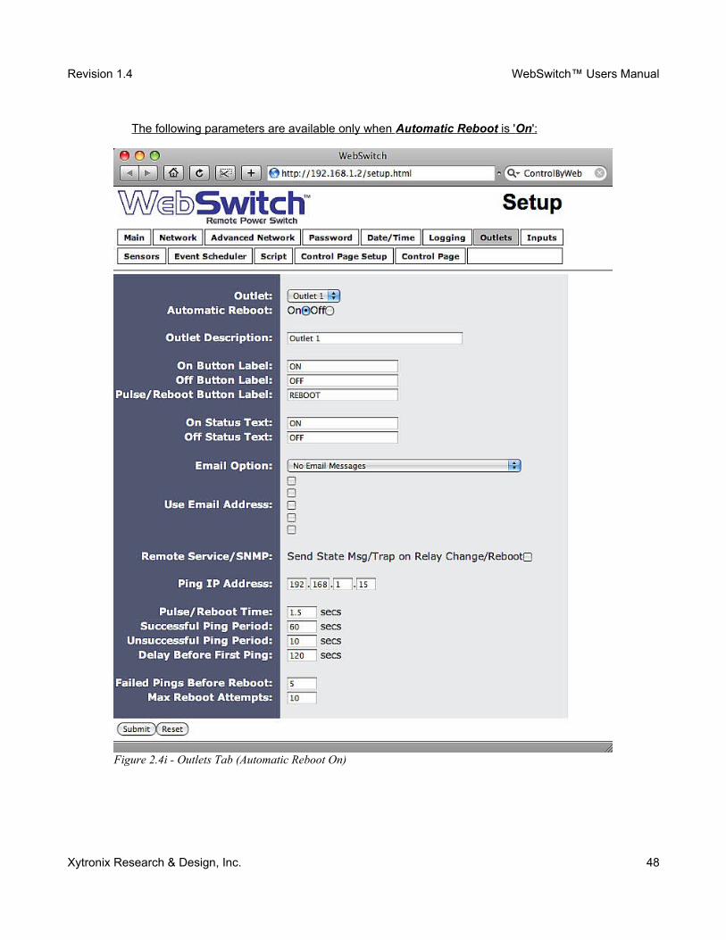
The following parameters are available only when Automatic Reboot is ' On ':
Xytronix Research & Design, Inc. 48
Figure 2.4i - Outlets Tab (Automatic Reboot On)
Revision 1.4 WebSwitch™ Users Manual
Ping IP Address
This is the IP address of the device that WebSwitch™ will ping. This is typically the IP address of thedevice that will be rebooted upon failure (such as a server, router, computer, etc.). It could, however,be the address of a device on the opposite side of a communications link when WebSwitch™ is used to reboot a communication device that does not have an IP address, such as a CSU/DSU, satellite modem, router, etc.
Pulse/Reboot Time
This is the time (in seconds) that WebSwitch™ pulses the outlet OFF and then back ON to reboot the device connected to the outlet. WebSwitch™ executes the reboot sequence when commanded by the user or when the automatic reboot controller determines that it is time to reboot. This time canbe set from 1 second to 60000 seconds (1000 minutes). The factory default for this setting is 10 seconds.
Successful Ping Period
This is the time interval (in seconds) between successful ping requests. This time can be set from 1 to 60000 seconds (1000 minutes or 16.6666 hours). The factory default for this setting is 60 seconds.
Unsuccessful Ping Period
When ping requests fail (no response from device), it may be desirable to begin pinging at a shorter time interval. This allows WebSwitch™ to determine in less time that the device is not functioning. After each unsuccessful ping, WebSwitch™ will wait this time interval (in seconds) before the next ping attempt. This time can be set from 1 to 60000 seconds (1000 minutes or 16.666 hours). The factory default for this setting is 10 seconds.
Delay Before First Ping
When WebSwitch™ is first powered, it will wait this time interval (in seconds) before beginning to ping the device. This time delay allows the device to boot before being pinged. This time can be set from 0 to 60000 seconds (1000 minutes or 16.666 hours). The factory default for this setting is 120 seconds.
Failed Pings Before Reboot
The device will be rebooted after this number of ping failures. This number can be set between 1 and 255. The factory default for this setting is 5.
Max Reboot Attempts
After the device has been rebooted this number of times without any successful pings, it is assumedthat there are problems with the device and WebSwitch™ will no longer attempt to reboot the device. At this point, WebSwitch™ will leave the device on and continue pinging the device, but will disable the auto-reboot feature. The auto-reboot feature will remain disabled until a user enables it through the Control Page, WebSwitch™ is powered down and powered up once again, or the device starts to respond to pings. This number can be set between 1 and 255. The factory default for this setting is 10.
Xytronix Research & Design, Inc. 49
Revision 1.4 WebSwitch™ Users Manual
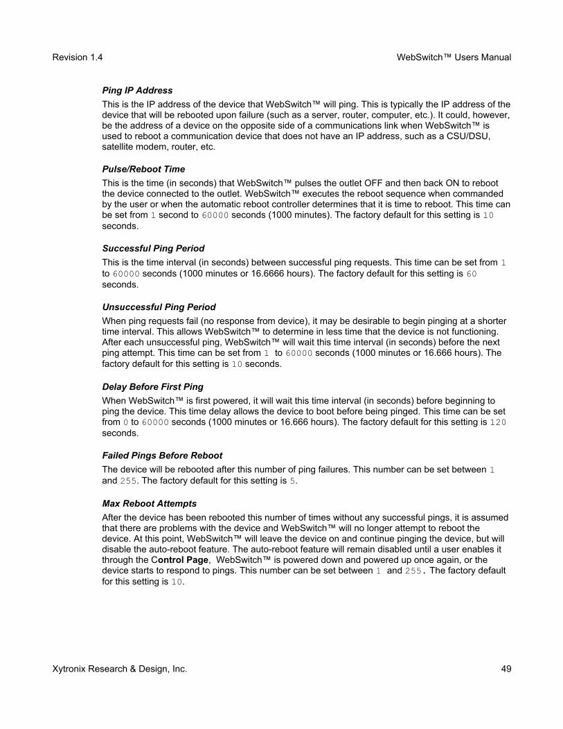
2.4.8 Inputs Tab (Model XRDI-WS3P only)
This page provides configuration options for the two control inputs built into WebSwitch Plus™.
Note: In this manual, the input is considered to be ON when the input is tied to ground.
Input
This drop down menu is used to select the control input to which the options below will apply.
-Input 1 or Input 2: Selects the control inputs.
Description
This text field is used to describe the function of the selected input. The text appears to the left of thecorresponding input status on the Control Page, and in email messages when email alerts are enabled. This field may be up to 24 characters long. The default text is Input #.
On Status Text
The text in this field specifies the text that will be displayed in the Control Page and in email messages when the input is ON (input tied to ground). Up to 15 characters may be entered in this field. The default text is ON.
Xytronix Research & Design, Inc. 50
Figure 2.4j- Inputs Tab

Revision 1.4 WebSwitch™ Users Manual
Off Status Text
The text in this field specifies the text that will be displayed in the control page and in email messages when the input is OFF (input is open). Up to 15 characters may be entered in this field. The default text is OFF.
Email Option
Simple email messages can be sent in response to input changes. This parameter is used to specifywhat input changes, if any, will cause email messages to be sent. Note that email notification will work only if the email settings are correctly set up in the Network setup page. The following options are available:
-No Email Messages: No email notifications will be sent due to input changes.-Send Email when input on: Email notifications will be sent when input state changes to on.-Send Email when input off: Email notifications will be sent when input state changes to off.-Send Email when input changes state: Email notifications will be sent when input changes state to on or off.
Note: The default setting for this field is No Email Messages.
Use Email Address
If email messages are to be sent out based on input changes, these check boxes specify to which email addresses the message will be sent. Email addresses specified on the Network setup tab will be displayed next to each check box. By default, no boxes are checked.
Remote Service/SNMP
When this box (Send State Msg/Trap on Input Change) is checked, SNMP traps and/or State messages will be sent whenever the input state changes.
Xytronix Research & Design, Inc. 51
Revision 1.4 WebSwitch™ Users Manual
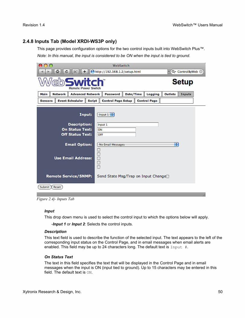
2.4.9 Sensors Tab (Model XRDI-WS3P only)
This tab is used to configure temperature/humidity sensors and associated alarms. WebSwitch Plus™ will automatically detect whether a temperature or humidity sensor is connected.
Sensor
Up to three sensors can be connected to WebSwitch Plus™. This drop-down list selects the sensor to be configured. The fields below are the same for each sensor.
Sensor Description
The text in this field appears to the left of the corresponding temperature/humidity reading on the Control Page. This text also appears in the email status message when email is enabled. This field can be up to 24 characters in length. The default text in this field is Sensor #.
Sensor Address
Each sensor connected to WebSwitch Plus™ should be associated (or assigned) to a sensor number. This identifies the name, location, and function of the sensor. Every temperature/humidity
Xytronix Research & Design, Inc. 52
Figure 2.4k- Sensors Tab
Revision 1.4 WebSwitch™ Users Manual
sensor comes from the factory with a unique, non-changeable address. When the sensors tab is selected (or the Refresh List button is pressed), WebSwitch Plus™ scans the bus for sensors. The addresses of the sensors that are found on the bus are listed in the drop-down list. For each sensor number (Sensor 1... Sensor 3), select the address of the appropriate sensor from the drop-down list.Selecting sensors is simplest when the sensors are connected to the bus one at a time. The procedure is to start with one sensor and associate it with the appropriate sensor number by selecting the sensor address within the appropriate drop-down list. Submit the page, connect a second sensor, and press the Refresh List button. Associate the second sensor to the appropriate sensor number. Continue this procedure until all sensors are set up.
Alarm 1
This setting is used to set the trigger point for an alarm condition. The number field specifies the temperature/humidity at which the alarm is triggered. The “High” and “Low” radio buttons indicate whether the alarm is triggered as a high or low alarm. A high alarm is triggered when the sensor reading exceeds the alarm value, and a low alarm is occurs when the sensor reading falls below the alarm value.
Alarm 2
This is a second alarm trigger that works similar to Alarm 1.
Deadband
This option sets the deadband used when evaluating alarm conditions. Deadband prevents alarms from triggering excessively when the sensor measurement vacillates quickly around the set point due to normal fluctuations. Deadband on high alarms requires the measurement to fall below the high alarm point minus the deadband before the high alarm can be triggered again. Likewise the deadband on the lower alarm requires the measurement to rise above the low alarm point plus the deadband before the low alarm can be triggered again For example, if the deadband is set to 1 degree, and a high alarm is to occur at 95 degrees, the dead band ensures that once the high alarm is triggered, it won't go off until the temperature return below 94 degrees (95 – 1). This reduces problems with small fluctuations in sensor readings triggering multiple alarms.
Xytronix Research & Design, Inc. 53
Figure 2.4l - Alarm Deadband
Revision 1.4 WebSwitch™ Users Manual
Email Option
Simple email messages can be sent in response to alarm conditions. This parameter is used to specify what alarm conditions, if any, will cause email messages to be sent. Note that email notification will work only if email is correctly setup in the Network setup page.
-No Email Messages: No email messages will be sent due to alarm conditions.-Send Email on Alarm 1: Email notifications will be sent due to Alarm 1 conditions.-Send Email on Alarm 2: Email notifications will be sent due to Alarm 2 conditions.-Send Email on Alarm 1 and Alarm 2: Email notifications will be sent due to Alarm 1 or Alarm 2 conditions.-Send Email on Alarm 1, Alarm 2, and Normal: Email notifications will be sent due to Alarm 1,Alarm 2, or when Normal conditions are regained.
Use Email Address
If email messages are to be sent out based on alarm conditions, these check boxes specify to whichemail addresses the message will be sent. Email address specified on the Network setup tab will beshown next to each check box.
Remote Services/SNMP
This field specifies the action with a remote server due to an alarm condition.
-No Action: No action is taken.-Send State Msg/Trap: An event string will be sent to the remote server.
For more information regarding the event string or other commands, see Appendix D: External Server and Remote Services.
The second drop down box specifies the conditions that will cause an alarm trigger. The following alarm conditions are available:
-Alarm 1: The specified action occurs due to Alarm 1.-Alarm 2: The specified action occurs due to Alarm 2.-Alarm 1 or Alarm 2: The specified action occurs due to Alarm 1 or Alarm 2.
Xytronix Research & Design, Inc. 54
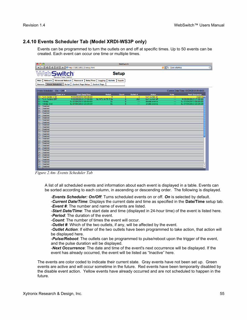
Revision 1.4 WebSwitch™ Users Manual
2.4.10 Events Scheduler Tab (Model XRDI-WS3P only)
Events can be programmed to turn the outlets on and off at specific times. Up to 50 events can be created. Each event can occur one time or multiple times.
A list of all scheduled events and information about each event is displayed in a table. Events can be sorted according to each column, in ascending or descending order. The following is displayed.
-Events Scheduler: On/Off: Turns scheduled events on or off. On is selected by default.-Current Date/Time: Displays the current date and time as specified in the Date/Time setup tab.-Event #: The number and name of events are listed.-Start Date/Time: The start date and time (displayed in 24-hour time) of the event is listed here.-Period: The duration of the event.-Count: The number of times the event will occur.-Outlet #: Which of the two outlets, if any, will be affected by the event.-Outlet Action: If either of the two outlets have been programmed to take action, that action will be displayed here.-Pulse/Reboot: The outlets can be programmed to pulse/reboot upon the trigger of the event, and the pulse duration will be displayed.-Next Occurrence: The date and time of the event's next occurrence will be displayed. If the event has already occurred, the event will be listed as “Inactive” here.
The events are color coded to indicate their current state. Gray events have not been set up. Green events are active and will occur sometime in the future. Red events have been temporarily disabled by the disable event action. Yellow events have already occurred and are not scheduled to happen in the future.
Xytronix Research & Design, Inc. 55
Figure 2.4m- Events Scheduler Tab
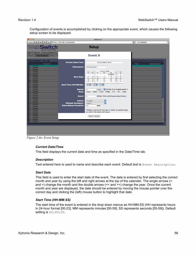
Revision 1.4 WebSwitch™ Users Manual
Configuration of events is accomplished by clicking on the appropriate event, which causes the followingsetup screen to be displayed:
Current Date/Time
This field displays the current date and time as specified in the Date/Time tab.
Description
Text entered here is used to name and describe each event. Default text is Event Description.
Start Date
This field is used to enter the start date of the event. The date is entered by first selecting the correctmonth and year by using the left and right arrows at the top of the calender. The single arrows (< and >) change the month and the double arrows (<< and >>) change the year. Once the current month and year are displayed, the date should be entered by moving the mouse pointer over the correct day and clicking the (left) mouse button to highlight that date.
Start Time (HH:MM:SS)
The start time of the event is entered in the drop down menus as HH:MM:SS (HH represents hours in 24-hour format [00-23], MM represents minutes [00-59], SS represents seconds [00-59]). Default setting is 00:00:00.
Xytronix Research & Design, Inc. 56
Figure 2.4n- Event Setup
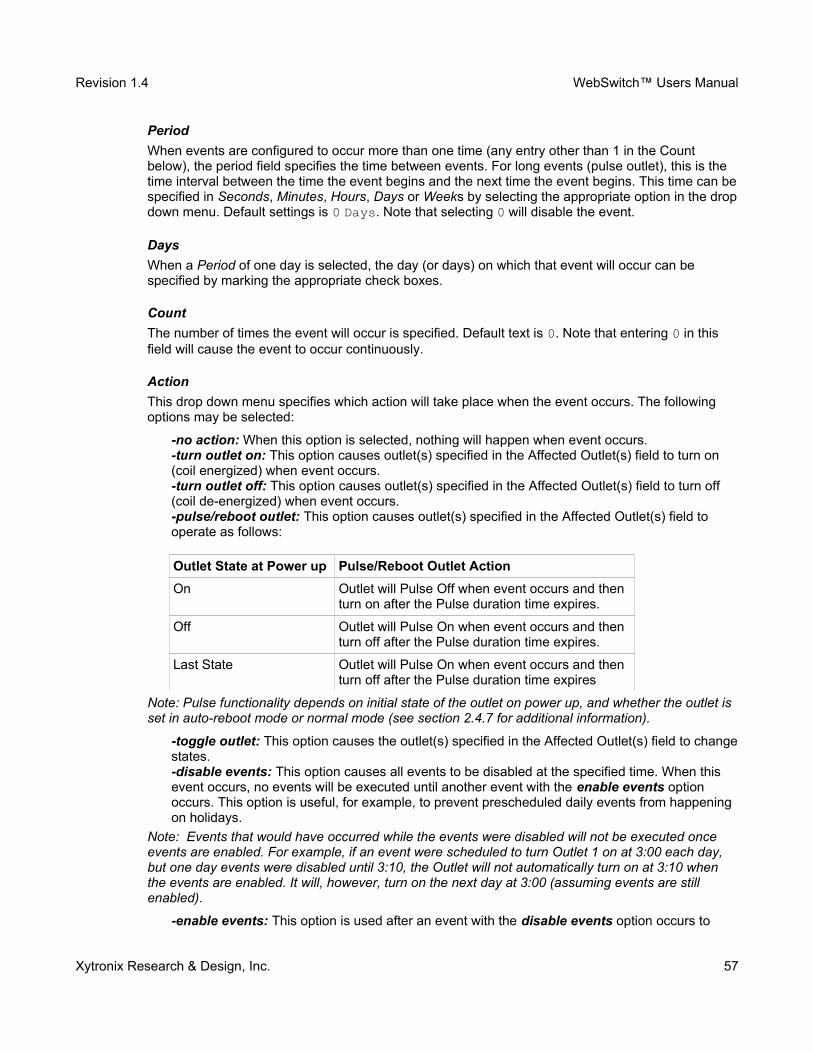
Revision 1.4 WebSwitch™ Users Manual
Period
When events are configured to occur more than one time (any entry other than 1 in the Count below), the period field specifies the time between events. For long events (pulse outlet), this is the time interval between the time the event begins and the next time the event begins. This time can bespecified in Seconds, Minutes, Hours, Days or Weeks by selecting the appropriate option in the dropdown menu. Default settings is 0 Days. Note that selecting 0 will disable the event.
Days
When a Period of one day is selected, the day (or days) on which that event will occur can be specified by marking the appropriate check boxes.
Count
The number of times the event will occur is specified. Default text is 0. Note that entering 0 in this field will cause the event to occur continuously.
Action
This drop down menu specifies which action will take place when the event occurs. The following options may be selected:
-no action: When this option is selected, nothing will happen when event occurs.-turn outlet on: This option causes outlet(s) specified in the Affected Outlet(s) field to turn on (coil energized) when event occurs.-turn outlet off: This option causes outlet(s) specified in the Affected Outlet(s) field to turn off (coil de-energized) when event occurs.-pulse/reboot outlet: This option causes outlet(s) specified in the Affected Outlet(s) field to operate as follows:
Outlet State at Power up Pulse/Reboot Outlet Action
On Outlet will Pulse Off when event occurs and then turn on after the Pulse duration time expires.
Off Outlet will Pulse On when event occurs and then turn off after the Pulse duration time expires.
Last State Outlet will Pulse On when event occurs and then turn off after the Pulse duration time expires
Note: Pulse functionality depends on initial state of the outlet on power up, and whether the outlet is set in auto-reboot mode or normal mode (see section 2.4.7 for additional information).
-toggle outlet: This option causes the outlet(s) specified in the Affected Outlet(s) field to changestates.-disable events: This option causes all events to be disabled at the specified time. When this event occurs, no events will be executed until another event with the enable events option occurs. This option is useful, for example, to prevent prescheduled daily events from happening on holidays.
Note: Events that would have occurred while the events were disabled will not be executed once events are enabled. For example, if an event were scheduled to turn Outlet 1 on at 3:00 each day, but one day events were disabled until 3:10, the Outlet will not automatically turn on at 3:10 when the events are enabled. It will, however, turn on the next day at 3:00 (assuming events are still enabled).
-enable events: This option is used after an event with the disable events option occurs to
Xytronix Research & Design, Inc. 57
Revision 1.4 WebSwitch™ Users Manual
allow events to resume.-set extVar0: External variables provide a way for scripts written in BASIC to interact with users,and for scripts to execute as a result of event occurrences. This option sets the variable extvar0 to 1 when the event occurs. If a running script uses this variable, it will function as defined in the script when the variable is set to 1.-clear extVar0: This option clears extvar0 (sets it to 0) when the event occurs. See description of set extVar0 for more information.
Affected Outlet(s)
This drop down menu is used to specify which of the outlets turn on upon occurrence of the event. One of the following options may be selected:
-outlet 1-outlet 2-both outlets
Pulse/Reboot Duration
If the Outlet Action has been set to pulse/reboot outlet, the Pulse/Reboot Duration is set in this field. The time is specified in seconds and can range from 0.1 seconds to 86400 seconds in 0.1 second increments. Default time is 1.5 seconds.
Xytronix Research & Design, Inc. 58
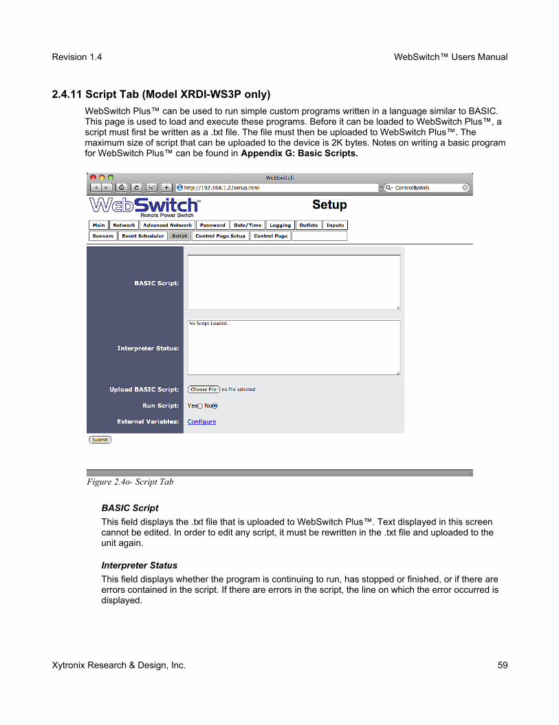
Revision 1.4 WebSwitch™ Users Manual
2.4.11 Script Tab (Model XRDI-WS3P only)
WebSwitch Plus™ can be used to run simple custom programs written in a language similar to BASIC. This page is used to load and execute these programs. Before it can be loaded to WebSwitch Plus™, a script must first be written as a .txt file. The file must then be uploaded to WebSwitch Plus™. The maximum size of script that can be uploaded to the device is 2K bytes. Notes on writing a basic programfor WebSwitch Plus™ can be found in Appendix G: Basic Scripts.
BASIC Script
This field displays the .txt file that is uploaded to WebSwitch Plus™. Text displayed in this screen cannot be edited. In order to edit any script, it must be rewritten in the .txt file and uploaded to the unit again.
Interpreter Status
This field displays whether the program is continuing to run, has stopped or finished, or if there are errors contained in the script. If there are errors in the script, the line on which the error occurred is displayed.
Xytronix Research & Design, Inc. 59
Figure 2.4o- Script Tab
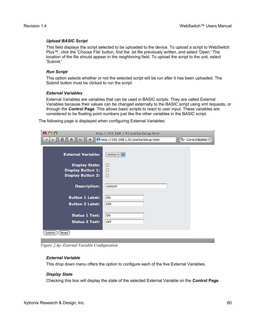
Revision 1.4 WebSwitch™ Users Manual
Upload BASIC Script
This field displays the script selected to be uploaded to the device. To upload a script to WebSwitch Plus™, click the 'Choose File' button, find the .txt file previously written, and select 'Open.' The location of the file should appear in the neighboring field. To upload the script to the unit, select 'Submit.'
Run Script
This option selects whether or not the selected script will be run after it has been uploaded. The Submit button must be clicked to run the script.
External Variables
External Variables are variables that can be used in BASIC scripts. They are called External Variables because their values can be changed externally to the BASIC script using xml requests, orthrough the Control Page. This allows basic scripts to react to user input. These variables are considered to be floating point numbers just like the other variables in the BASIC script.
The following page is displayed when configuring External Variables:
External Variable
This drop down menu offers the option to configure each of the five External Variables.
Display State
Checking this box will display the state of the selected External Variable on the Control Page.
Xytronix Research & Design, Inc. 60
Figure 2.4p- External Variable Configuration
Revision 1.4 WebSwitch™ Users Manual
Display Button 1
Checking this box will display a button on the Control Page. Clicking this button on the Control Page will set the extVar to value 1.
Display Button 2
Checking this box will display a button on the Control Page. Clicking this button will set the extVar to value 2.
Description
Text entered here will be displayed in the left column of the control page. Up to 24 characters may be entered here. The default text is extVar#.
Button 1 Label
This text field is used to describe the function of button 1 of the selected extVar. The text also appears to the right of the corresponding extVar status. Up to 15 characters may be entered here. By default, this text is ON for a value of 1.
Button 2 Label
This text field is used to describe the function of button 2 of the selected extVar. The text also appears to the right of the corresponding extVar status. Up to 15 characters may be entered here. By default, this text is OFF with a value of 0.
Status 1 Text
The text in this field specifies the text that will be displayed when the extVar is value 1, with a gray background. The text also appears in the status column on the Control Page. Up to 15 characters may be entered here. By default the text is ON.
Status 2 Text
The text in this field specifies the text that will be displayed when the extVar is value 0, with a gray background. The text also appears in the status column on the Control Page. Note that if the extVaris any other value than 1 or 0, the value will be displayed in the same column, with a gray background. Up to 15 characters may be entered here. By default the text is OFF.
Xytronix Research & Design, Inc. 61
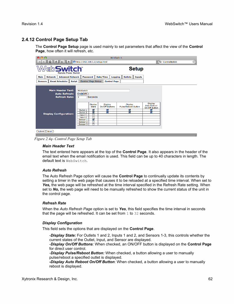
Revision 1.4 WebSwitch™ Users Manual
2.4.12 Control Page Setup Tab
The Control Page Setup page is used mainly to set parameters that affect the view of the Control Page, how often it will refresh, etc.
Main Header Text
The text entered here appears at the top of the Control Page. It also appears in the header of the email text when the email notification is used. This field can be up to 40 characters in length. The default text is WebSwitch.
Auto Refresh
The Auto Refresh Page option will cause the Control Page to continually update its contents by setting a timer in the web page that causes it to be reloaded at a specified time interval. When set toYes, the web page will be refreshed at the time interval specified in the Refresh Rate setting. When set to No, the web page will need to be manually refreshed to show the current status of the unit in the control page.
Refresh Rate
When the Auto Refresh Page option is set to Yes, this field specifies the time interval in seconds that the page will be refreshed. It can be set from 1 to 32 seconds.
Display Configuration
This field sets the options that are displayed on the Control Page.
-Display State: For Outlets 1 and 2, Inputs 1 and 2, and Sensors 1-3, this controls whether the current states of the Outlet, Input, and Sensor are displayed.-Display On/Off Buttons: When checked, an ON/OFF button is displayed on the Control Page for direct user control.-Display Pulse/Reboot Button: When checked, a button allowing a user to manually pulse/reboot a specified outlet is displayed.-Display Auto Reboot On/Off Button: When checked, a button allowing a user to manually reboot is displayed.
Xytronix Research & Design, Inc. 62
Figure 2.4q- Control Page Setup Tab
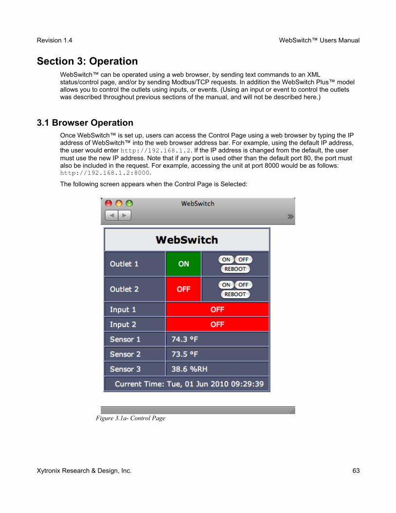
Revision 1.4 WebSwitch™ Users Manual
Section 3: OperationWebSwitch™ can be operated using a web browser, by sending text commands to an XML status/control page, and/or by sending Modbus/TCP requests. In addition the WebSwitch Plus™ model allows you to control the outlets using inputs, or events. (Using an input or event to control the outlets was described throughout previous sections of the manual, and will not be described here.)
3.1 Browser OperationOnce WebSwitch™ is set up, users can access the Control Page using a web browser by typing the IP address of WebSwitch™ into the web browser address bar. For example, using the default IP address, the user would enter http://192.168.1.2. If the IP address is changed from the default, the user must use the new IP address. Note that if any port is used other than the default port 80, the port must also be included in the request. For example, accessing the unit at port 8000 would be as follows: http://192.168.1.2:8000.
The following screen appears when the Control Page is Selected:
Xytronix Research & Design, Inc. 63
Figure 3.1a- Control Page
Revision 1.4 WebSwitch™ Users Manual
Header
Displays the text entered in the Main Header Text field on the Control Page Setup tab in the setup pages.
Outlet 1 and 2
These rows display the current state of the two outlets and allow the user to change the outlet state. Each of these rows can be displayed (as shown) or not displayed by checking or unchecking the appropriate boxes on the Control Page Setup tab in the setup pages. The text in the left column (by default reads Outlet 1 and Outlet 2) is specified in the Description field in the Outlets tab in the setup pages. The state of the outlet is shown to the right of the outlet description text. By default, thestatus text will read ON or OFF; however, the status text can be changed in the Outlets tab. To the right of the outlet status, buttons are provided to control the outlets. The buttons can be removed when needed (in the Control Page Setup tab) and the text within the buttons can be customized (in the Outlets tab).
Input 1 and 2 (Model XRDI-WS3P only)
These rows display the current state of the two inputs. Each row can be displayed (as shown) or not displayed by checking or unchecking the appropriate boxes in the Control Page Setup tab in the setup pages. The text in the left column (by default reads Input 1 and Input 2) is specified in theDescription field in the Inputs tab in the setup pages.
Sensor 1-3 (Model XRDI-WS3P only)
These rows display the current temperature or humidity measured by the associated sensors. Each row can be displayed (as shown) or not displayed by checking or unchecking the appropriate boxes under the Control Page Setup tab in the setup pages. The text in the left column (by default reads Sensor 1 through Sensor 3), is specified in the Sensor Description field under the Sensors tab in the setup pages.
Current Time (Model XRDI-WS3P only)
Displays the current time that is set using the Date/Time tab in the setup pages.
Note: If the sensors are not configured (sensor addresses selected for each sensor) or are unreadable, the display will read x.x rather than displaying a false numerical value.
Xytronix Research & Design, Inc. 64
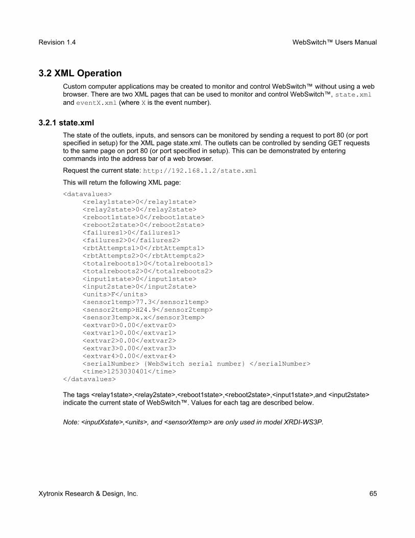
Revision 1.4 WebSwitch™ Users Manual
3.2 XML OperationCustom computer applications may be created to monitor and control WebSwitch™ without using a web browser. There are two XML pages that can be used to monitor and control WebSwitch™, state.xml and eventX.xml (where X is the event number).
3.2.1 state.xml
The state of the outlets, inputs, and sensors can be monitored by sending a request to port 80 (or port specified in setup) for the XML page state.xml. The outlets can be controlled by sending GET requests to the same page on port 80 (or port specified in setup). This can be demonstrated by entering commands into the address bar of a web browser.
Request the current state: http://192.168.1.2/state.xml
This will return the following XML page:
<datavalues><relay1state>0</relay1state><relay2state>0</relay2state><reboot1state>0</reboot1state><reboot2state>0</reboot2state><failures1>0</failures1><failures2>0</failures2><rbtAttempts1>0</rbtAttempts1><rbtAttempts2>0</rbtAttempts2><totalreboots1>0</totalreboots1><totalreboots2>0</totalreboots2><input1state>0</input1state><input2state>0</input2state><units>F</units><sensor1temp>77.3</sensor1temp><sensor2temp>H24.9</sensor2temp><sensor3temp>x.x</sensor3temp><extvar0>0.00</extvar0><extvar1>0.00</extvar1><extvar2>0.00</extvar2><extvar3>0.00</extvar3><extvar4>0.00</extvar4><serialNumber> {WebSwitch serial number} </serialNumber><time>1253030401</time>
</datavalues>
The tags <relay1state>,<relay2state>,<reboot1state>,<reboot2state>,<input1state>,and <input2state> indicate the current state of WebSwitch™. Values for each tag are described below.
Note: <inputXstate>,<units>, and <sensorXtemp> are only used in model XRDI-WS3P.
Xytronix Research & Design, Inc. 65
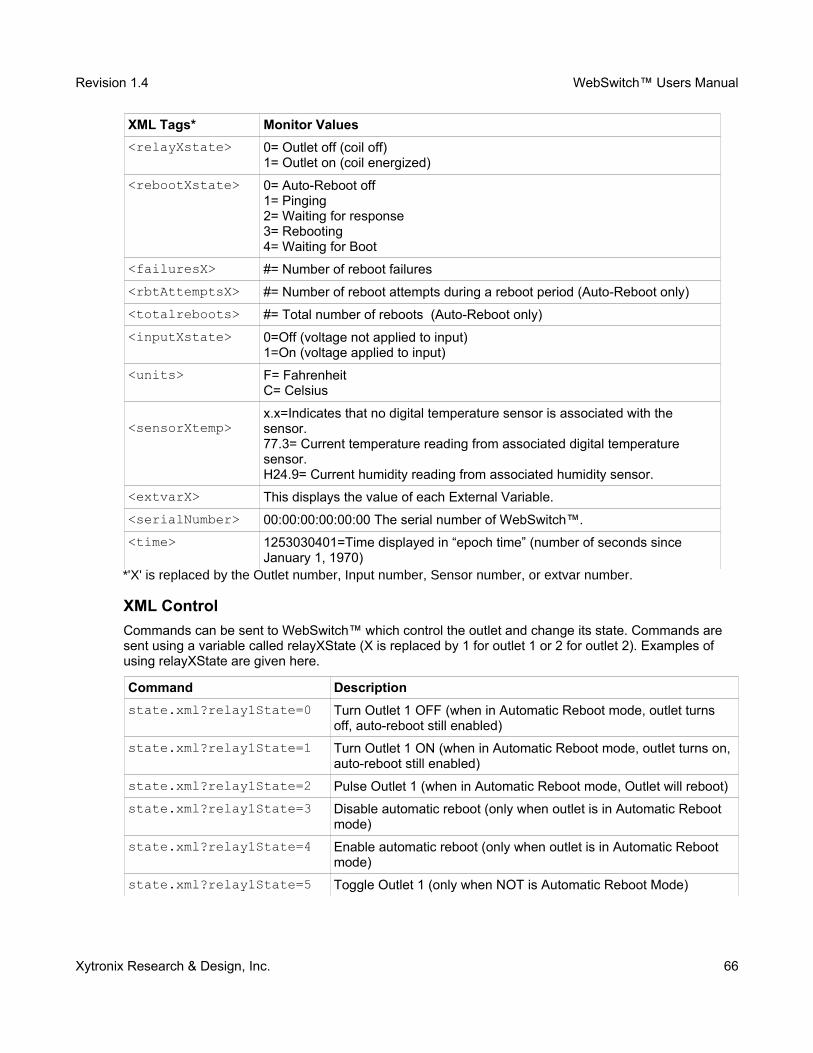
Revision 1.4 WebSwitch™ Users Manual
XML Tags* Monitor Values
<relayXstate> 0= Outlet off (coil off)1= Outlet on (coil energized)
<rebootXstate> 0= Auto-Reboot off1= Pinging2= Waiting for response3= Rebooting4= Waiting for Boot
<failuresX> #= Number of reboot failures
<rbtAttemptsX> #= Number of reboot attempts during a reboot period (Auto-Reboot only)
<totalreboots> #= Total number of reboots (Auto-Reboot only)
<inputXstate>
0=Off (voltage not applied to input) 1=On (voltage applied to input)
<units> F= FahrenheitC= Celsius
<sensorXtemp>x.x=Indicates that no digital temperature sensor is associated with the sensor.77.3= Current temperature reading from associated digital temperature sensor.H24.9= Current humidity reading from associated humidity sensor.
<extvarX> This displays the value of each External Variable.
<serialNumber> 00:00:00:00:00:00 The serial number of WebSwitch™.
<time> 1253030401=Time displayed in “epoch time” (number of seconds since January 1, 1970)
*'X' is replaced by the Outlet number, Input number, Sensor number, or extvar number.
XML Control
Commands can be sent to WebSwitch™ which control the outlet and change its state. Commands are sent using a variable called relayXState (X is replaced by 1 for outlet 1 or 2 for outlet 2). Examples of using relayXState are given here.
Command Description
state.xml?relay1State=0 Turn Outlet 1 OFF (when in Automatic Reboot mode, outlet turns off, auto-reboot still enabled)
state.xml?relay1State=1 Turn Outlet 1 ON (when in Automatic Reboot mode, outlet turns on, auto-reboot still enabled)
state.xml?relay1State=2 Pulse Outlet 1 (when in Automatic Reboot mode, Outlet will reboot)
state.xml?relay1State=3 Disable automatic reboot (only when outlet is in Automatic Reboot mode)
state.xml?relay1State=4 Enable automatic reboot (only when outlet is in Automatic Reboot mode)
state.xml?relay1State=5 Toggle Outlet 1 (only when NOT is Automatic Reboot Mode)
Xytronix Research & Design, Inc. 66
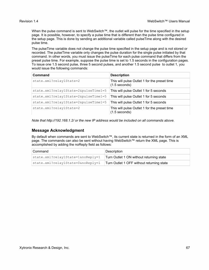
Revision 1.4 WebSwitch™ Users Manual
When the pulse command is sent to WebSwitch™, the outlet will pulse for the time specified in the setuppage. It is possible, however, to specify a pulse time that is different than the pulse time configured in the setup page. This is done by sending an additional variable called pulseTime along with the desired pulse time.
The pulseTime variable does not change the pulse time specified in the setup page and is not stored or recorded. The pulseTime variable only changes the pulse duration for the single pulse initiated by that command. In other words, you must issue the pulseTime for each pulse command that differs from the preset pulse time. For example, suppose the pulse time is set to 1.5 seconds in the configuration pages. To issue one 1.5 second pulse, three 5 second pulses, and another 1.5 second pulse to outlet 1, you would issue the following commands:
Command Description
state.xml?relay1State=2 This will pulse Outlet 1 for the preset time (1.5 seconds)
state.xml?relay1State=2&pulseTime1=5 This will pulse Outlet 1 for 5 seconds
state.xml?relay1State=2&pulseTime1=5 This will pulse Outlet 1 for 5 seconds
state.xml?relay1State=2&pulseTime1=5 This will pulse Outlet 1 for 5 seconds
state.xml?relay1State=2 This will pulse Outlet 1 for the preset time (1.5 seconds)
Note that http://192.168.1.2/ or the new IP address would be included on all commands above.
Message Acknowledgment
By default when commands are sent to WebSwitch™, its current state is returned in the form of an XML page. The commands can also be sent without having WebSwitch™ return the XML page. This is accomplished by adding the noReply field as follows:
Command Description
state.xml?relay1State=1&noReply=1 Turn Outlet 1 ON without returning state
state.xml?relay1State=0&noReply=1 Turn Outlet 1 OFF without returning state
Xytronix Research & Design, Inc. 67
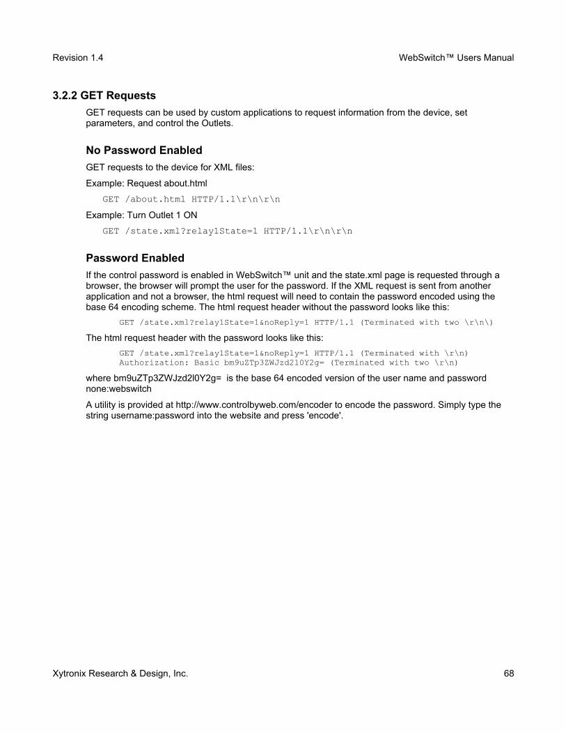
Revision 1.4 WebSwitch™ Users Manual
3.2.2 GET Requests
GET requests can be used by custom applications to request information from the device, set parameters, and control the Outlets.
No Password Enabled
GET requests to the device for XML files:
Example: Request about.html
GET /about.html HTTP/1.1\r\n\r\n
Example: Turn Outlet 1 ON
GET /state.xml?relay1State=1 HTTP/1.1\r\n\r\n
Password Enabled
If the control password is enabled in WebSwitch™ unit and the state.xml page is requested through a browser, the browser will prompt the user for the password. If the XML request is sent from another application and not a browser, the html request will need to contain the password encoded using the base 64 encoding scheme. The html request header without the password looks like this:
GET /state.xml?relay1State=1&noReply=1 HTTP/1.1 (Terminated with two \r\n\)
The html request header with the password looks like this:
GET /state.xml?relay1State=1&noReply=1 HTTP/1.1 (Terminated with \r\n)Authorization: Basic bm9uZTp3ZWJzd210Y2g= (Terminated with two \r\n)
where bm9uZTp3ZWJzd2l0Y2g= is the base 64 encoded version of the user name and password none:webswitch
A utility is provided at http://www.controlbyweb.com/encoder to encode the password. Simply type the string username:password into the website and press 'encode'.
Xytronix Research & Design, Inc. 68
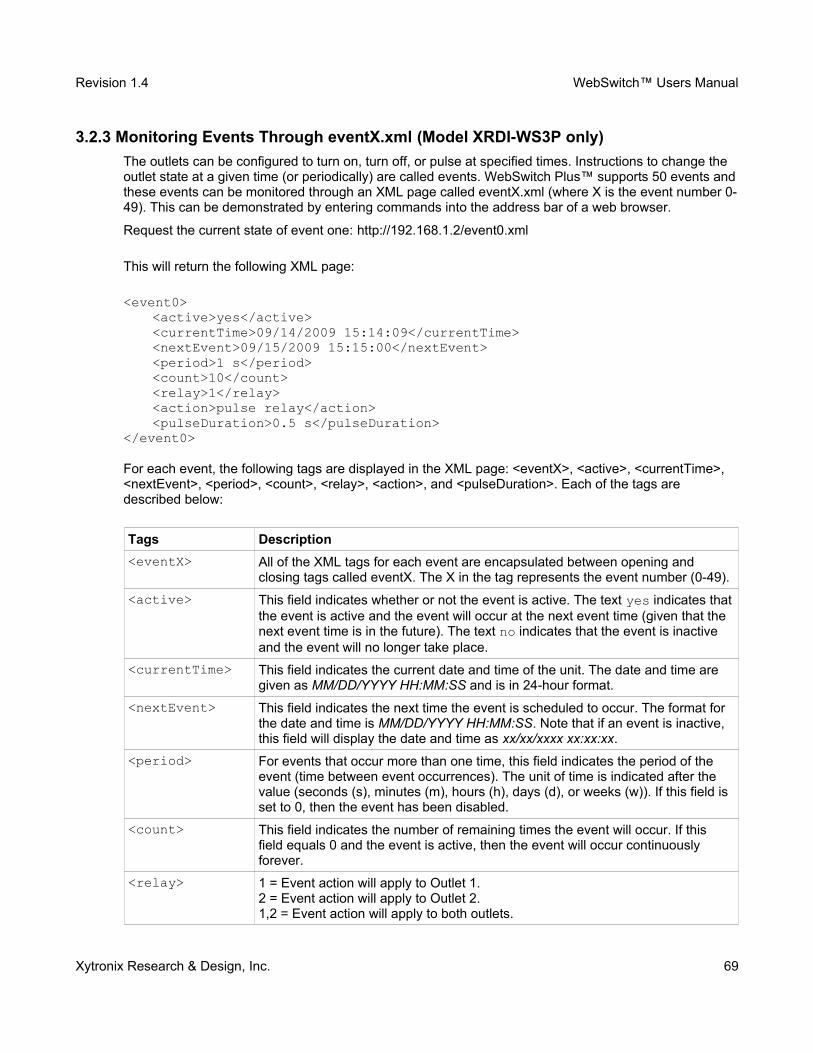
Revision 1.4 WebSwitch™ Users Manual
3.2.3 Monitoring Events Through eventX.xml (Model XRDI-WS3P only)
The outlets can be configured to turn on, turn off, or pulse at specified times. Instructions to change the outlet state at a given time (or periodically) are called events. WebSwitch Plus™ supports 50 events andthese events can be monitored through an XML page called eventX.xml (where X is the event number 0-49). This can be demonstrated by entering commands into the address bar of a web browser.
Request the current state of event one: http://192.168.1.2/event0.xml
This will return the following XML page:
<event0><active>yes</active><currentTime>09/14/2009 15:14:09</currentTime><nextEvent>09/15/2009 15:15:00</nextEvent><period>1 s</period><count>10</count><relay>1</relay><action>pulse relay</action><pulseDuration>0.5 s</pulseDuration>
</event0>
For each event, the following tags are displayed in the XML page: <eventX>, <active>, <currentTime>, <nextEvent>, <period>, <count>, <relay>, <action>, and <pulseDuration>. Each of the tags are described below:
Tags Description
<eventX> All of the XML tags for each event are encapsulated between opening and closing tags called eventX. The X in the tag represents the event number (0-49).
<active> This field indicates whether or not the event is active. The text yes indicates thatthe event is active and the event will occur at the next event time (given that the next event time is in the future). The text no indicates that the event is inactive and the event will no longer take place.
<currentTime> This field indicates the current date and time of the unit. The date and time are given as MM/DD/YYYY HH:MM:SS and is in 24-hour format.
<nextEvent> This field indicates the next time the event is scheduled to occur. The format for the date and time is MM/DD/YYYY HH:MM:SS. Note that if an event is inactive, this field will display the date and time as xx/xx/xxxx xx:xx:xx.
<period> For events that occur more than one time, this field indicates the period of the event (time between event occurrences). The unit of time is indicated after the value (seconds (s), minutes (m), hours (h), days (d), or weeks (w)). If this field is set to 0, then the event has been disabled.
<count> This field indicates the number of remaining times the event will occur. If this field equals 0 and the event is active, then the event will occur continuously forever.
<relay> 1 = Event action will apply to Outlet 1.2 = Event action will apply to Outlet 2.1,2 = Event action will apply to both outlets.
Xytronix Research & Design, Inc. 69

Revision 1.4 WebSwitch™ Users Manual
<action> ON (Outlet will turn on when event occurs.)OFF (Outlet will turn off when event occurs.)Pulse (Outlet will pulse when event occurs.)Toggle (Outlet will toggle state when event occurs.)
<pulseDuration> When the event causes the outlet to pulse, this field indicates the time (in seconds) that the outlet will pulse.
Xytronix Research & Design, Inc. 70
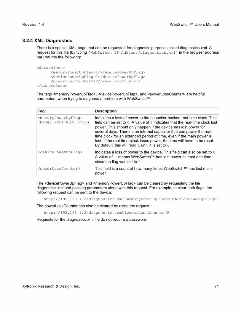
Revision 1.4 WebSwitch™ Users Manual
3.2.4 XML Diagnostics
There is a special XML page that can be requested for diagnostic purposes called diagnostics.xml. A request for this file (by typing {WebSwitch IP Address/diagnostics.xml} in the browser addressbar) returns the following:
<datavalues> <memoryPowerUpFlag>1</memoryPowerUpFlag> <devicePowerUpFlag>1</devicePowerUpFlag> <powerLossCounter>1</powerLossCounter></datavalues>
The tags <memoryPowerUpFlag>, <devicePowerUpFlap>, and <powerLossCounter> are helpful parameters when trying to diagnose a problem with WebSwitch™.
Tag Description
<memoryPowerUpFlag>(Model XRDI-WS3P only)
Indicates a loss of power to the capacitor-backed real-time clock. This field can be set to 0. A value of 1 indicates that the real-time clock lostpower. This should only happen if the device has lost power for several days. There is an internal capacitor that can power the real-time clock for an extended period of time, even if the main power is lost. If the real-time-clock loses power, the time will have to be reset. By default, this will read 1 until it is set to 0.
<devicePowerUpFlag> Indicates a loss of power to the device. This field can also be set to 0. A value of 1 means WebSwitch™ has lost power at least one time since the flag was set to 0.
<powerLossCounter> This field is a count of how many times WebSwitch™ has lost main power.
The <devicePowerUpFlag> and <memoryPowerUpFlag> can be cleared by requesting the file diagnostics.xml and passing parameters along with this request. For example, to clear both flags, the following request can be sent to the device:
http://192.168.1.2/diagnostics.xml?memoryPowerUpFlag=0&devicePowerUpFlag=0
The powerLossCounter can also be cleared by using the request:
http://192.168.1.2/diagnostics.xml?powerLossCounter=0
Requests for the diagnostics.xml file do not require a password.
Xytronix Research & Design, Inc. 71
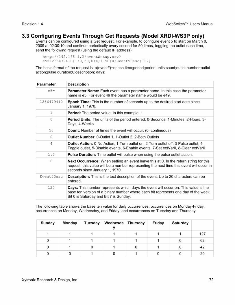
Revision 1.4 WebSwitch™ Users Manual
3.3 Configuring Events Through Get Requests (Model XRDI-WS3P only)Events can be configured using a Get request. For example, to configure event 5 to start on March 8, 2009 at 02:30:10 and continue periodically every second for 50 times, toggling the outlet each time, send the following request (using the default IP address):
http://192.168.1.2/eventSetup.srv?e5=1236479410;1;0;50;0;4;1.50;0;Event5Desc;127;
The basic format of the request is: e(event#)=epoch time;period;period units;count;outlet number;outlet action;pulse duration;0;description; days;
Parameter Description
e5= Parameter Name: Each event has a parameter name. In this case the parameter name is e5. For event 49 the parameter name would be e49.
1236479410 Epoch Time: This is the number of seconds up to the desired start date since January 1, 1970.
1 Period: The period value. In this example, 1
0 Period Units: The units of the period entered. 0-Seconds, 1-Minutes, 2-Hours, 3-Days, 4-Weeks
50 Count: Number of times the event will occur. (0=continuous)
0 Outlet Number: 0-Outlet 1, 1-Outlet 2, 2-Both Outlets
4 Outlet Action: 0-No Action, 1-Turn outlet on, 2-Turn outlet off, 3-Pulse outlet, 4-Toggle outlet, 5-Disable events, 6-Enable events, 7-Set extVar0, 8-Clear extVar0
1.5 Pulse Duration: Time outlet will pulse when using the pulse outlet action.
0 Next Occurrence: When setting an event leave this at 0. In the return string for this request, this value will be a number representing the next time this event will occur inseconds since January 1, 1970.
Event5Desc Description: This is the text description of the event. Up to 20 characters can be entered.
127 Days: This number represents which days the event will occur on. This value is the base ten version of a binary number where each bit represents one day of the week. Bit 0 is Saturday and Bit 7 is Sunday.
The following table shows the base ten value for daily occurrences, occurrences on Monday-Friday, occurrences on Monday, Wednesday, and Friday, and occurrences on Tuesday and Thursday:
Sunday Monday Tuesday Wednesday
Thursday Friday Saturday
1 1 1 1 1 1 1 127
0 1 1 1 1 1 0 62
0 1 0 1 0 1 0 42
0 0 1 0 1 0 0 20
Xytronix Research & Design, Inc. 72
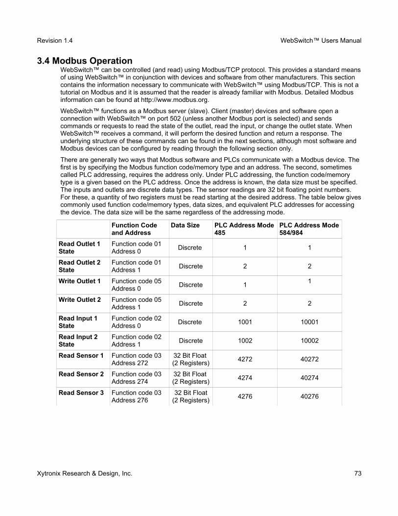
Revision 1.4 WebSwitch™ Users Manual
3.4 Modbus OperationWebSwitch™ can be controlled (and read) using Modbus/TCP protocol. This provides a standard meansof using WebSwitch™ in conjunction with devices and software from other manufacturers. This section contains the information necessary to communicate with WebSwitch™ using Modbus/TCP. This is not a tutorial on Modbus and it is assumed that the reader is already familiar with Modbus. Detailed Modbus information can be found at http://www.modbus.org.
WebSwitch™ functions as a Modbus server (slave). Client (master) devices and software open a connection with WebSwitch™ on port 502 (unless another Modbus port is selected) and sends commands or requests to read the state of the outlet, read the input, or change the outlet state. When WebSwitch™ receives a command, it will perform the desired function and return a response. The underlying structure of these commands can be found in the next sections, although most software and Modbus devices can be configured by reading through the following section only.
There are generally two ways that Modbus software and PLCs communicate with a Modbus device. The first is by specifying the Modbus function code/memory type and an address. The second, sometimes called PLC addressing, requires the address only. Under PLC addressing, the function code/memory type is a given based on the PLC address. Once the address is known, the data size must be specified. The inputs and outlets are discrete data types. The sensor readings are 32 bit floating point numbers. For these, a quantity of two registers must be read starting at the desired address. The table below givescommonly used function code/memory types, data sizes, and equivalent PLC addresses for accessing the device. The data size will be the same regardless of the addressing mode.
Function Code and Address
Data Size PLC Address Mode485
PLC Address Mode584/984
Read Outlet 1 State
Function code 01Address 0
Discrete 1 1
Read Outlet 2 State
Function code 01Address 1
Discrete 2 2
Write Outlet 1 Function code 05Address 0
Discrete 11
Write Outlet 2 Function code 05Address 1
Discrete 2 2
Read Input 1 State
Function code 02Address 0
Discrete 1001 10001
Read Input 2 State
Function code 02Address 1
Discrete 1002 10002
Read Sensor 1 Function code 03Address 272
32 Bit Float (2 Registers)
4272 40272
Read Sensor 2 Function code 03Address 274
32 Bit Float (2 Registers)
4274 40274
Read Sensor 3 Function code 03Address 276
32 Bit Float(2 Registers)
4276 40276
Xytronix Research & Design, Inc. 73
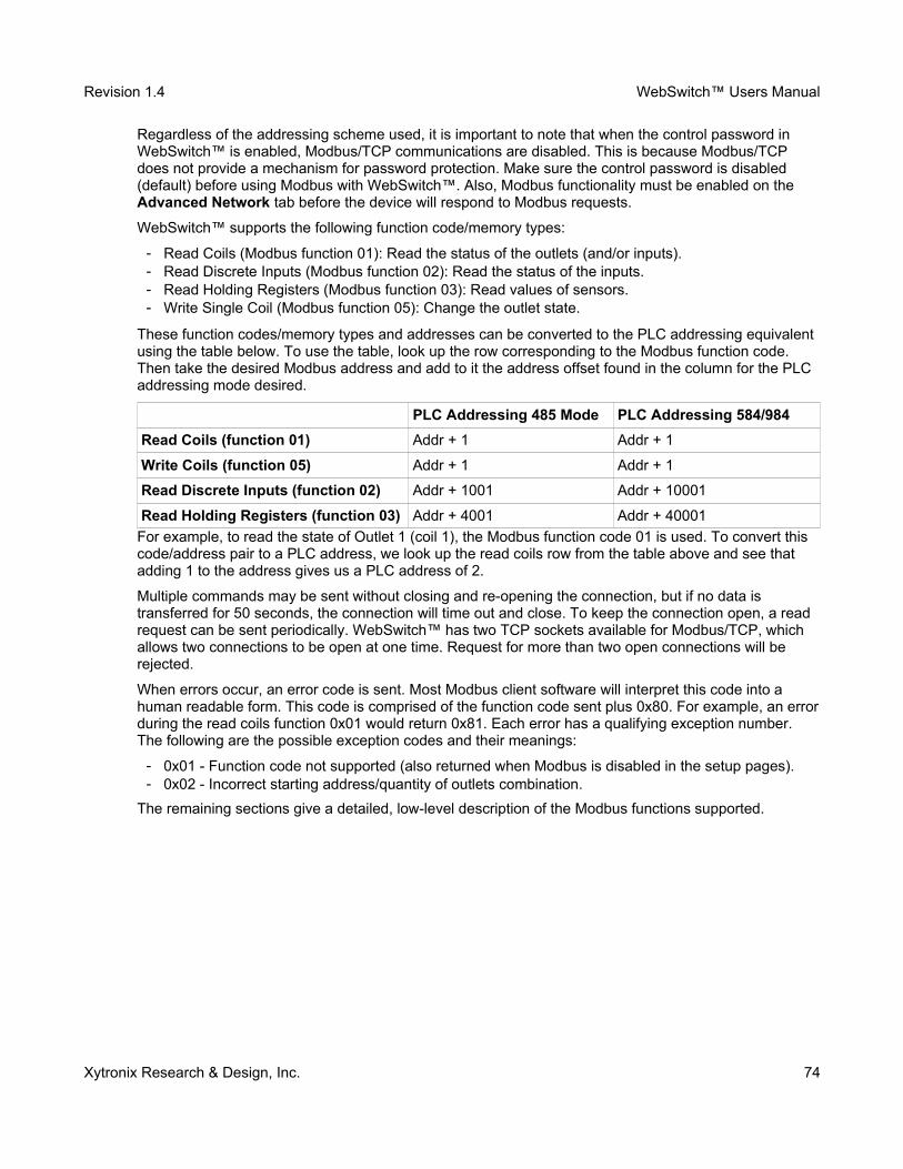
Revision 1.4 WebSwitch™ Users Manual
Regardless of the addressing scheme used, it is important to note that when the control password in WebSwitch™ is enabled, Modbus/TCP communications are disabled. This is because Modbus/TCP does not provide a mechanism for password protection. Make sure the control password is disabled (default) before using Modbus with WebSwitch™. Also, Modbus functionality must be enabled on the Advanced Network tab before the device will respond to Modbus requests.
WebSwitch™ supports the following function code/memory types:
━ Read Coils (Modbus function 01): Read the status of the outlets (and/or inputs). ━ Read Discrete Inputs (Modbus function 02): Read the status of the inputs. ━ Read Holding Registers (Modbus function 03): Read values of sensors.━ Write Single Coil (Modbus function 05): Change the outlet state.
These function codes/memory types and addresses can be converted to the PLC addressing equivalent using the table below. To use the table, look up the row corresponding to the Modbus function code. Then take the desired Modbus address and add to it the address offset found in the column for the PLC addressing mode desired.
PLC Addressing 485 Mode PLC Addressing 584/984
Read Coils (function 01) Addr + 1 Addr + 1
Write Coils (function 05) Addr + 1 Addr + 1
Read Discrete Inputs (function 02) Addr + 1001 Addr + 10001
Read Holding Registers (function 03) Addr + 4001 Addr + 40001
For example, to read the state of Outlet 1 (coil 1), the Modbus function code 01 is used. To convert this code/address pair to a PLC address, we look up the read coils row from the table above and see that adding 1 to the address gives us a PLC address of 2.
Multiple commands may be sent without closing and re-opening the connection, but if no data is transferred for 50 seconds, the connection will time out and close. To keep the connection open, a read request can be sent periodically. WebSwitch™ has two TCP sockets available for Modbus/TCP, which allows two connections to be open at one time. Request for more than two open connections will be rejected.
When errors occur, an error code is sent. Most Modbus client software will interpret this code into a human readable form. This code is comprised of the function code sent plus 0x80. For example, an errorduring the read coils function 0x01 would return 0x81. Each error has a qualifying exception number. The following are the possible exception codes and their meanings:
━ 0x01 - Function code not supported (also returned when Modbus is disabled in the setup pages).━ 0x02 - Incorrect starting address/quantity of outlets combination.
The remaining sections give a detailed, low-level description of the Modbus functions supported.
Xytronix Research & Design, Inc. 74
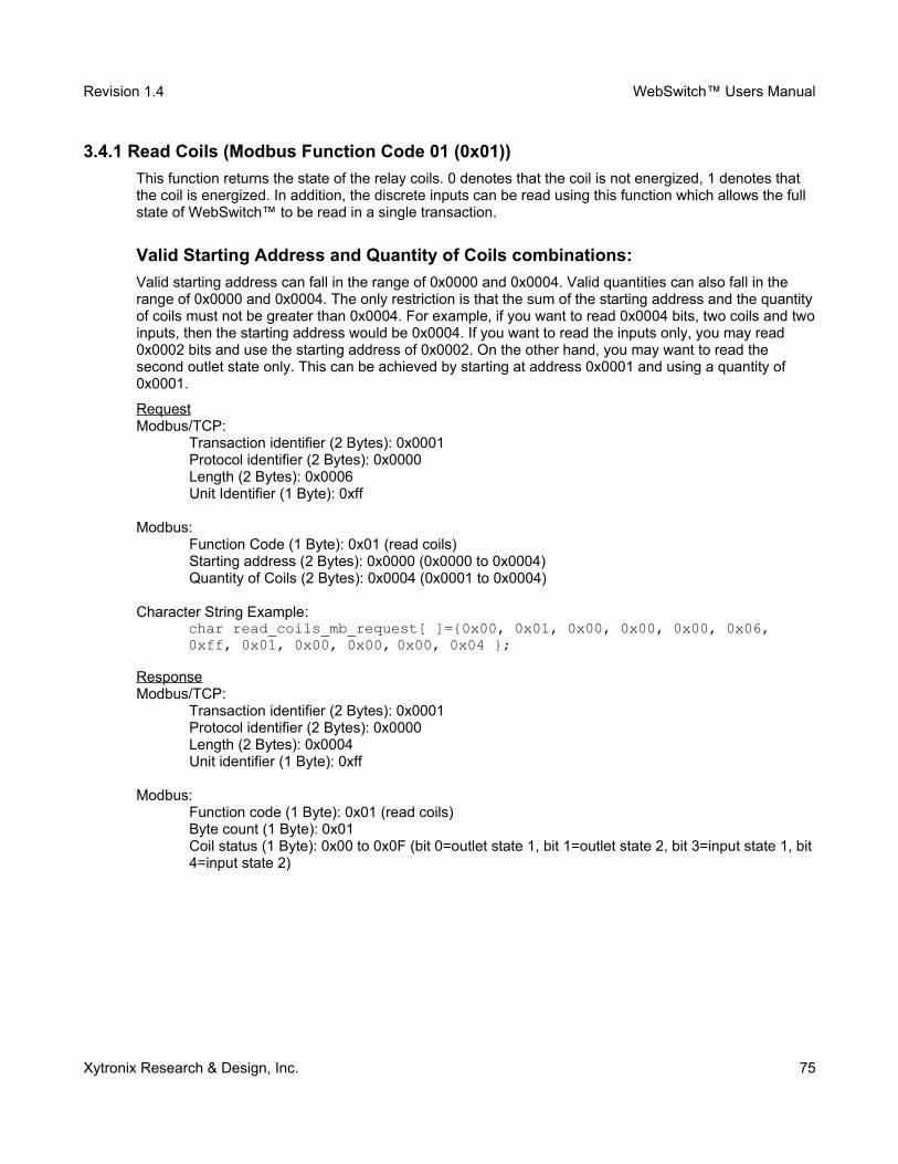
Revision 1.4 WebSwitch™ Users Manual
3.4.1 Read Coils (Modbus Function Code 01 (0x01))
This function returns the state of the relay coils. 0 denotes that the coil is not energized, 1 denotes that the coil is energized. In addition, the discrete inputs can be read using this function which allows the full state of WebSwitch™ to be read in a single transaction.
Valid Starting Address and Quantity of Coils combinations:
Valid starting address can fall in the range of 0x0000 and 0x0004. Valid quantities can also fall in the range of 0x0000 and 0x0004. The only restriction is that the sum of the starting address and the quantityof coils must not be greater than 0x0004. For example, if you want to read 0x0004 bits, two coils and twoinputs, then the starting address would be 0x0004. If you want to read the inputs only, you may read 0x0002 bits and use the starting address of 0x0002. On the other hand, you may want to read the second outlet state only. This can be achieved by starting at address 0x0001 and using a quantity of 0x0001.
RequestModbus/TCP:
Transaction identifier (2 Bytes): 0x0001Protocol identifier (2 Bytes): 0x0000Length (2 Bytes): 0x0006Unit Identifier (1 Byte): 0xff
Modbus:Function Code (1 Byte): 0x01 (read coils)Starting address (2 Bytes): 0x0000 (0x0000 to 0x0004)Quantity of Coils (2 Bytes): 0x0004 (0x0001 to 0x0004)
Character String Example:char read_coils_mb_request[ ]={0x00, 0x01, 0x00, 0x00, 0x00, 0x06, 0xff, 0x01, 0x00, 0x00, 0x00, 0x04 };
ResponseModbus/TCP:
Transaction identifier (2 Bytes): 0x0001Protocol identifier (2 Bytes): 0x0000Length (2 Bytes): 0x0004Unit identifier (1 Byte): 0xff
Modbus:Function code (1 Byte): 0x01 (read coils)Byte count (1 Byte): 0x01Coil status (1 Byte): 0x00 to 0x0F (bit 0=outlet state 1, bit 1=outlet state 2, bit 3=input state 1, bit4=input state 2)
Xytronix Research & Design, Inc. 75
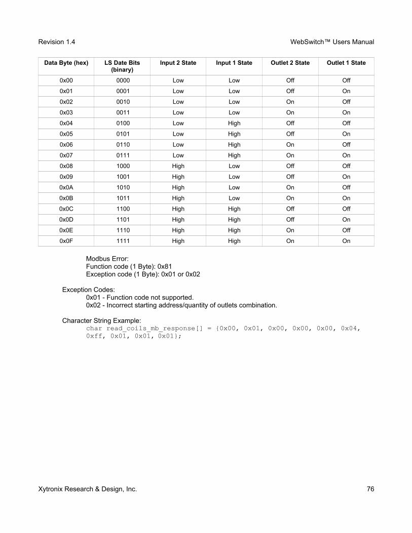
Revision 1.4 WebSwitch™ Users Manual
Data Byte (hex) LS Date Bits(binary)
Input 2 State Input 1 State Outlet 2 State Outlet 1 State
0x00 10000 Low Low Off Off
0x01 10001 Low Low Off On
0x02 10010 Low Low On Off
0x03 10011 Low Low On On
0x04 10100 Low High Off Off
0x05 10101 Low High Off On
0x06 10110 Low High On Off
0x07 10111 Low High On On
0x08 11000 High Low Off Off
0x09 11001 High Low Off On
0x0A 11010 High Low On Off
0x0B 11011 High Low On On
0x0C 11100 High High Off Off
0x0D 11101 High High Off On
0x0E 11110 High High On Off
0x0F 11111 High High On On
Modbus Error:Function code (1 Byte): 0x81Exception code (1 Byte): 0x01 or 0x02
Exception Codes:0x01 - Function code not supported.0x02 - Incorrect starting address/quantity of outlets combination.
Character String Example: char read_coils_mb_response[] = {0x00, 0x01, 0x00, 0x00, 0x00, 0x04, 0xff, 0x01, 0x01, 0x01};
Xytronix Research & Design, Inc. 76
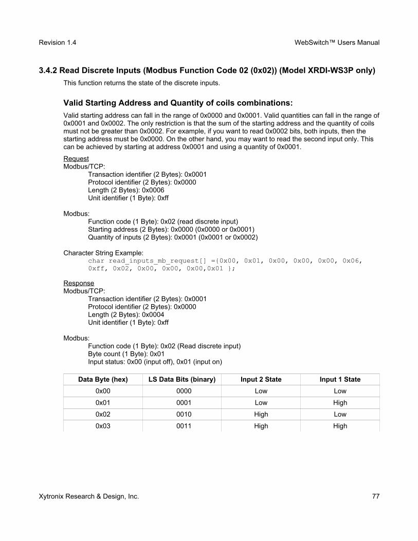
Revision 1.4 WebSwitch™ Users Manual
3.4.2 Read Discrete Inputs (Modbus Function Code 02 (0x02)) (Model XRDI-WS3P only)
This function returns the state of the discrete inputs.
Valid Starting Address and Quantity of coils combinations:
Valid starting address can fall in the range of 0x0000 and 0x0001. Valid quantities can fall in the range of0x0001 and 0x0002. The only restriction is that the sum of the starting address and the quantity of coils must not be greater than 0x0002. For example, if you want to read 0x0002 bits, both inputs, then the starting address must be 0x0000. On the other hand, you may want to read the second input only. This can be achieved by starting at address 0x0001 and using a quantity of 0x0001.
RequestModbus/TCP:
Transaction identifier (2 Bytes): 0x0001Protocol identifier (2 Bytes): 0x0000Length (2 Bytes): 0x0006Unit identifier (1 Byte): 0xff
Modbus:Function code (1 Byte): 0x02 (read discrete input)Starting address (2 Bytes): 0x0000 (0x0000 or 0x0001)Quantity of inputs (2 Bytes): 0x0001 (0x0001 or 0x0002)
Character String Example:char read_inputs_mb_request[] ={0x00, 0x01, 0x00, 0x00, 0x00, 0x06, 0xff, 0x02, 0x00, 0x00, 0x00,0x01 };
ResponseModbus/TCP:
Transaction identifier (2 Bytes): 0x0001Protocol identifier (2 Bytes): 0x0000Length (2 Bytes): 0x0004Unit identifier (1 Byte): 0xff
Modbus:Function code (1 Byte): 0x02 (Read discrete input)Byte count (1 Byte): 0x01Input status: 0x00 (input off), 0x01 (input on)
Data Byte (hex) LS Data Bits (binary) Input 2 State Input 1 State
0x00 10000 Low Low
0x01 10001 Low High
0x02 10010 High Low
0x03 10011 High High
Xytronix Research & Design, Inc. 77

Revision 1.4 WebSwitch™ Users Manual
Modbus Error:Function code (1 Byte): 0x82Exception code (1 Byte): 0x01 or 0x02
Exception Codes:0x01 - Function code not supported,0x02 - Incorrect starting address / quantity of outlets combination.
Character String Example: char read_inputs_mb_response[] = {0x00, 0x01, 0x00, 0x00, 0x00, 0x04, 0xff, 0x02, 0x01, 0x01 };
Xytronix Research & Design, Inc. 78
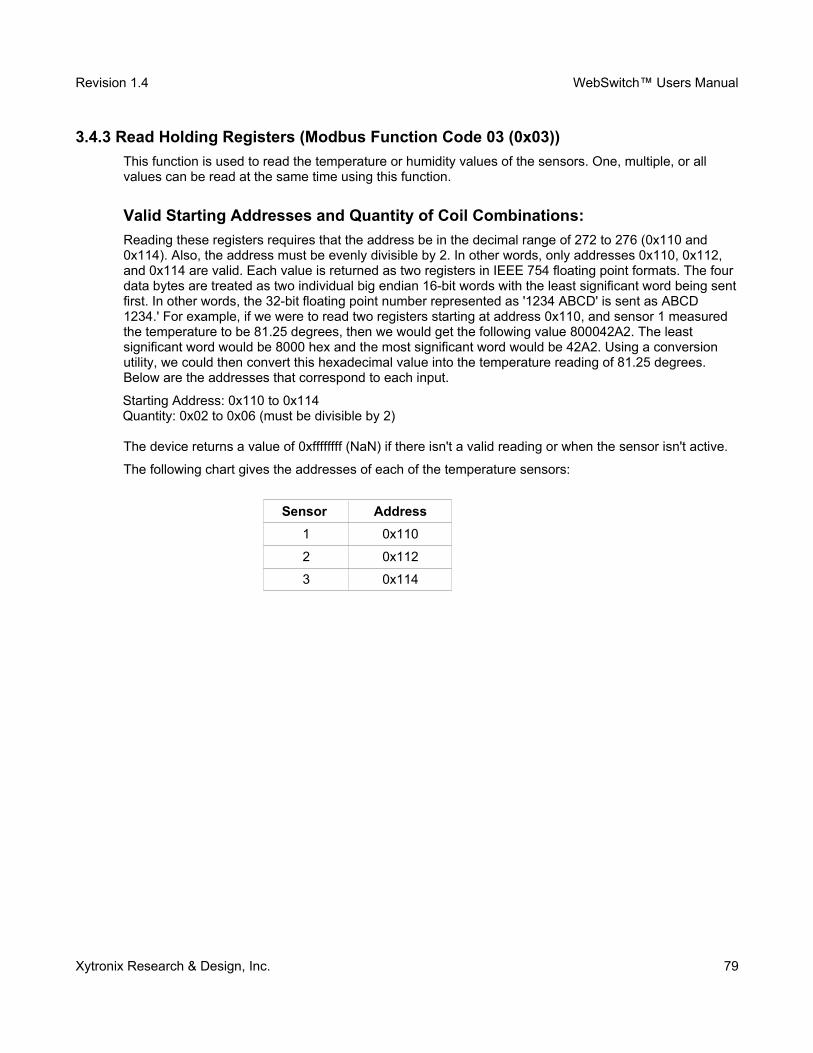
Revision 1.4 WebSwitch™ Users Manual
3.4.3 Read Holding Registers (Modbus Function Code 03 (0x03))
This function is used to read the temperature or humidity values of the sensors. One, multiple, or all values can be read at the same time using this function.
Valid Starting Addresses and Quantity of Coil Combinations:
Reading these registers requires that the address be in the decimal range of 272 to 276 (0x110 and 0x114). Also, the address must be evenly divisible by 2. In other words, only addresses 0x110, 0x112, and 0x114 are valid. Each value is returned as two registers in IEEE 754 floating point formats. The four data bytes are treated as two individual big endian 16-bit words with the least significant word being sentfirst. In other words, the 32-bit floating point number represented as '1234 ABCD' is sent as ABCD 1234.' For example, if we were to read two registers starting at address 0x110, and sensor 1 measured the temperature to be 81.25 degrees, then we would get the following value 800042A2. The least significant word would be 8000 hex and the most significant word would be 42A2. Using a conversion utility, we could then convert this hexadecimal value into the temperature reading of 81.25 degrees. Below are the addresses that correspond to each input.
Starting Address: 0x110 to 0x114Quantity: 0x02 to 0x06 (must be divisible by 2)
The device returns a value of 0xffffffff (NaN) if there isn't a valid reading or when the sensor isn't active.
The following chart gives the addresses of each of the temperature sensors:
Sensor Address
1 0x110
2 0x112
3 0x114
Xytronix Research & Design, Inc. 79
Revision 1.4 WebSwitch™ Users Manual
3.4.4 Write Single Coil (Modbus Function Code 05 (0x05))
This function allows you to turn Outlets 1 and 2 on and off, one at a time.
RequestModbus/TCP:
Transaction identifier (2 Bytes): 0x0001Protocol identifier (2 Bytes): 0x0000Length (2 Bytes): 0x0006Unit identifier (1 Byte): 0xff
Modbus:Function code (1 Byte): 0x05 (write coil)Outlet address (2 Bytes): 0x0000 or 0x0001 (outlet 1 = 0x0000, outlet 2 = 0x0001)Outlet value (1 Byte): 0xff - turn outlet on, 0x00 - turn outlet offPadding (1 Byte): 0x00
Character String Example:char write_coil_mb_request[] = {0x00, 0x01, 0x00, 0x00, 0x00, 0x06, 0xff, 0x05, 0x00, 0x00, 0xff, 0x00};
ResponseModbus/TCP:
Transaction identifier (2 Bytes): 0x0001Protocol identifier (2 Bytes): 0x0000Length(2 Bytes): 0x0006Unit identifier (1 Byte): 0xff
Modbus:Function code (1 Byte): 0x05 (write coil)Outlet address (2 Bytes): 0x0000Outlet value (1 Byte): 0xff - outlet on, 0x00 - outlet offPadding (1 Byte): 0x00
Modbus Error:Function code (1 Byte): 0x85Exception code (1 Byte): 0x01 or 0x02
Exception Codes:0x01 - Function code not supported.0x02 - Incorrect starting address / quantity of outlets combination.
Character String Example:char write_coils_mb_response[] = {0x00, 0x01, 0x00, 0x00, 0x00, 0x06, 0xff, 0x05, 0x00, 0x00, 0xff, 0x00 };
Xytronix Research & Design, Inc. 80
Revision 1.4 WebSwitch™ Users Manual
3.5 Email Notification (Model XRDI-WS3P only)
3.5.1 Email Notification Description
WebSwitch Plus™ can be configured to send an email message to up to five email addresses when certain events happen. Events that can trigger email messages include input state changes, outlet state changes, temperature/humidity changes, and commands sent from a BASIC script.
When an email message is sent, it looks similar to this:
WebSwitchTrigger: Outlet 1: ON
Outlet 1: ONOutlet 2: OFFInput 1: ONInput 2: OFFSensor 1: 73.5
Note: Text shown in bold is set by the user (installer). Note: Inputs and Sensors are available on model XRDI-WS3P only.
Subject Line
The top line (that reads WebSwitch), appears in the subject line of the email message. This is the same text that appears as the header on the Control Page. It is set in the Main Header Text field under the Control Page Setup tab.
Trigger
The first line displayed in the body of the message shows what triggered the message. The text “Trigger”will always appear and cannot be changed. The remaining text includes the Trigger, the current state of the outlet and input, and the current temperature/humidity of the sensor. The text that describes the trigger and its current state are configured in the setup pages as described below.
Current Status of Outlets, Inputs, and Sensors
The remainder of the email message will display the same information shown on the Control Page. Any information omitted from the Control Page will not be included in the email message. If inputs, outlets, or sensors are not displayed on the Control Page, the email message will not include anything except the Subject Line and the Trigger. The name for each input, outlet, and sensor is defined in the 'Description' fields for the inputs, outlets, and sensors. The text that describes the current status of the outlets, inputs, and sensors is defined in the 'On Status Text' and 'Off Status Text' within the setup tabs for the outlets, inputs, and sensors.
Xytronix Research & Design, Inc. 81
Revision 1.4 WebSwitch™ Users Manual
3.5.2 Email Notification Setup
Email notification requires the following fields are properly set. See Section 2 for a description of each field.
Network Tab:━ IP Address━ Subnet Mask━ Gateway━ Preferred DNS Server (this is required if Mail Server is entered by name and not by IP address) ━ Mail Server (SMTP)━ User Name (If Required)━ Password (If Required)━ Return Email━ Email 1 (additional Email addresses may be entered)
Once the settings under the Network tab are entered correctly, an email trigger(s) must be configured. An email trigger can be generated within a BASIC script (See Appendix G for information about BASIC scripts), or can be explicitly defined for each outlet, input, and sensor (under Outlets, Inputs, and Sensors tabs). For each outlet, input, and sensor trigger, the “Email Option' field should be set to the appropriate trigger. Finally, the appropriate email addresses should be selected for each outlet, input, and sensor trigger by checking the box next to the desired email address under the Outlets, Inputs, andSensors tabs.
Once the email settings are entered, the email functionality can be tested by entering the following command:
http://192.168.1.2/state.xml?testEmail=1
This will cause an email message to be sent immediately. If the message doesn't get through, the system log file may have some clues to assist in diagnosing the problem
http://192.168.1.2/syslog.txt
Xytronix Research & Design, Inc. 82
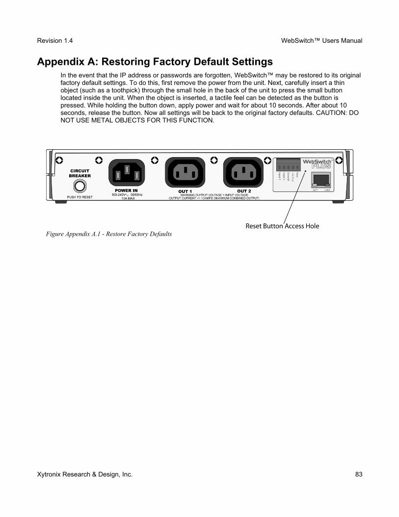
Revision 1.4 WebSwitch™ Users Manual
Appendix A: Restoring Factory Default SettingsIn the event that the IP address or passwords are forgotten, WebSwitch™ may be restored to its originalfactory default settings. To do this, first remove the power from the unit. Next, carefully insert a thin object (such as a toothpick) through the small hole in the back of the unit to press the small button located inside the unit. When the object is inserted, a tactile feel can be detected as the button is pressed. While holding the button down, apply power and wait for about 10 seconds. After about 10 seconds, release the button. Now all settings will be back to the original factory defaults. CAUTION: DO NOT USE METAL OBJECTS FOR THIS FUNCTION.
Xytronix Research & Design, Inc. 83
Figure Appendix A.1 - Restore Factory Defaults
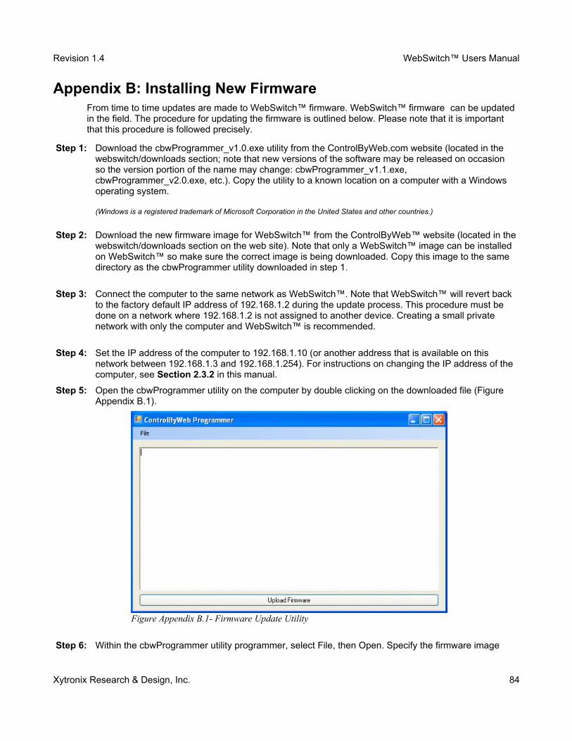
Revision 1.4 WebSwitch™ Users Manual
Appendix B: Installing New FirmwareFrom time to time updates are made to WebSwitch™ firmware. WebSwitch™ firmware can be updated in the field. The procedure for updating the firmware is outlined below. Please note that it is important that this procedure is followed precisely.
Step 1: Download the cbwProgrammer_v1.0.exe utility from the ControlByWeb.com website (located in the webswitch/downloads section; note that new versions of the software may be released on occasion so the version portion of the name may change: cbwProgrammer_v1.1.exe, cbwProgrammer_v2.0.exe, etc.). Copy the utility to a known location on a computer with a Windows operating system.
(Windows is a registered trademark of Microsoft Corporation in the United States and other countries.)
Step 2: Download the new firmware image for WebSwitch™ from the ControlByWeb™ website (located in thewebswitch/downloads section on the web site). Note that only a WebSwitch™ image can be installed on WebSwitch™ so make sure the correct image is being downloaded. Copy this image to the same directory as the cbwProgrammer utility downloaded in step 1.
Step 3: Connect the computer to the same network as WebSwitch™. Note that WebSwitch™ will revert back to the factory default IP address of 192.168.1.2 during the update process. This procedure must be done on a network where 192.168.1.2 is not assigned to another device. Creating a small private network with only the computer and WebSwitch™ is recommended.
Step 4: Set the IP address of the computer to 192.168.1.10 (or another address that is available on this network between 192.168.1.3 and 192.168.1.254). For instructions on changing the IP address of the computer, see Section 2.3.2 in this manual.
Step 5: Open the cbwProgrammer utility on the computer by double clicking on the downloaded file (Figure Appendix B.1).
Step 6: Within the cbwProgrammer utility programmer, select File, then Open. Specify the firmware image
Xytronix Research & Design, Inc. 84
Figure Appendix B.1- Firmware Update Utility

Revision 1.4 WebSwitch™ Users Manual
downloaded from the ControlByWeb™ web site.
Step 7: Carefully follow these steps:(a) Remove power to WebSwitch™.(b) Press and hold the reset button as described in Appendix A.(c) While holding the reset button, apply power to WebSwitch™. The Link and Act lights will flash. Continue to hold the reset button without releasing for the next step.(d) While holding the reset button, press the Upload Firmware button at the bottom of the ControlByWeb™ Programmer window.(e) After the programming process begins, the reset button can be released.
Step 8: Wait for Link LED to turn on such that it is continuously on. This may take up to 10-20 seconds. Programming should be complete. WebSwitch™ will be set to factory defaults with an IP address of 192.168.1.2. Verify the new version of firmware has been installed by viewing the default setup page with a web browser (http://192.168.1.2/setup.html).
Xytronix Research & Design, Inc. 85
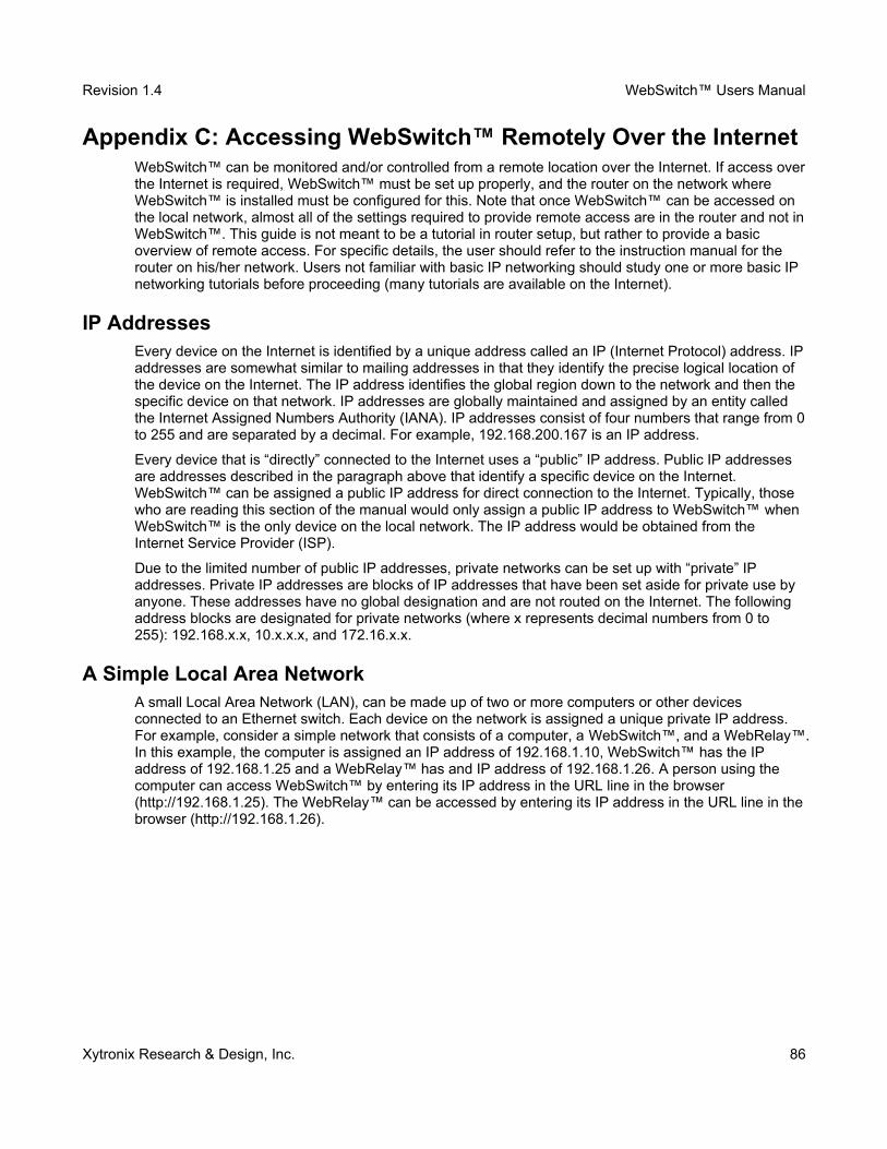
Revision 1.4 WebSwitch™ Users Manual
Appendix C: Accessing WebSwitch™ Remotely Over the Internet WebSwitch™ can be monitored and/or controlled from a remote location over the Internet. If access overthe Internet is required, WebSwitch™ must be set up properly, and the router on the network where WebSwitch™ is installed must be configured for this. Note that once WebSwitch™ can be accessed on the local network, almost all of the settings required to provide remote access are in the router and not inWebSwitch™. This guide is not meant to be a tutorial in router setup, but rather to provide a basic overview of remote access. For specific details, the user should refer to the instruction manual for the router on his/her network. Users not familiar with basic IP networking should study one or more basic IP networking tutorials before proceeding (many tutorials are available on the Internet).
IP AddressesEvery device on the Internet is identified by a unique address called an IP (Internet Protocol) address. IPaddresses are somewhat similar to mailing addresses in that they identify the precise logical location of the device on the Internet. The IP address identifies the global region down to the network and then the specific device on that network. IP addresses are globally maintained and assigned by an entity called the Internet Assigned Numbers Authority (IANA). IP addresses consist of four numbers that range from 0to 255 and are separated by a decimal. For example, 192.168.200.167 is an IP address.
Every device that is “directly” connected to the Internet uses a “public” IP address. Public IP addresses are addresses described in the paragraph above that identify a specific device on the Internet. WebSwitch™ can be assigned a public IP address for direct connection to the Internet. Typically, those who are reading this section of the manual would only assign a public IP address to WebSwitch™ when WebSwitch™ is the only device on the local network. The IP address would be obtained from the Internet Service Provider (ISP).
Due to the limited number of public IP addresses, private networks can be set up with “private” IP addresses. Private IP addresses are blocks of IP addresses that have been set aside for private use by anyone. These addresses have no global designation and are not routed on the Internet. The following address blocks are designated for private networks (where x represents decimal numbers from 0 to 255): 192.168.x.x, 10.x.x.x, and 172.16.x.x.
A Simple Local Area NetworkA small Local Area Network (LAN), can be made up of two or more computers or other devices connected to an Ethernet switch. Each device on the network is assigned a unique private IP address. For example, consider a simple network that consists of a computer, a WebSwitch™, and a WebRelay™.In this example, the computer is assigned an IP address of 192.168.1.10, WebSwitch™ has the IP address of 192.168.1.25 and a WebRelay™ has and IP address of 192.168.1.26. A person using the computer can access WebSwitch™ by entering its IP address in the URL line in the browser (http://192.168.1.25). The WebRelay™ can be accessed by entering its IP address in the URL line in thebrowser (http://192.168.1.26).
Xytronix Research & Design, Inc. 86
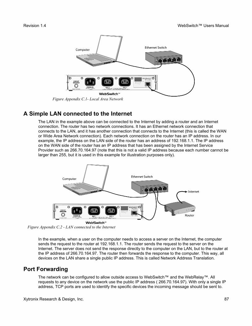
Revision 1.4 WebSwitch™ Users Manual
A Simple LAN connected to the InternetThe LAN in the example above can be connected to the Internet by adding a router and an Internet connection. The router has two network connections. It has an Ethernet network connection that connects to the LAN, and it has another connection that connects to the Internet (this is called the WAN or Wide Area Network connection). Each network connection on the router has an IP address. In our example, the IP address on the LAN side of the router has an address of 192.168.1.1. The IP address on the WAN side of the router has an IP address that has been assigned by the Internet Service Provider such as 266.70.164.97 (note that this is not a valid IP address because each number cannot belarger than 255, but it is used in this example for illustration purposes only).
In the example, when a user on the computer needs to access a server on the Internet, the computer sends the request to the router at 192.168.1.1. The router sends the request to the server on the Internet. The server does not send the response directly to the computer on the LAN, but to the router atthe IP address of 266.70.164.97. The router then forwards the response to the computer. This way, all devices on the LAN share a single public IP address. This is called Network Address Translation.
Port ForwardingThe network can be configured to allow outside access to WebSwitch™ and the WebRelay™. All requests to any device on the network use the public IP address ( 266.70.164.97). With only a single IP address, TCP ports are used to identify the specific devices the incoming message should be sent to.
Xytronix Research & Design, Inc. 87
Figure Appendix C.1- Local Area Network
Figure Appendix C.2 - LAN connected to the Internet
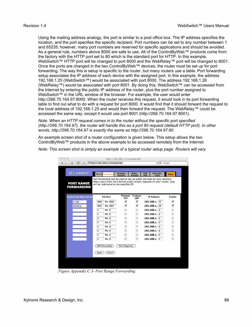
Revision 1.4 WebSwitch™ Users Manual
Using the mailing address analogy, the port is similar to a post office box. The IP address specifies the location, and the port specifies the specific recipient. Port numbers can be set to any number between 1 and 65235; however, many port numbers are reserved for specific applications and should be avoided. As a general rule, numbers above 8000 are safe to use. All of the ControlByWeb™ products come from the factory with the HTTP port set to 80 which is the standard port for HTTP. In this example, WebSwitch™ HTTP port will be changed to port 8000 and the WebRelay™ port will be changed to 8001.Once the ports are changed in the two ControlByWeb™ devices, the router must be set up for port forwarding. The way this is setup is specific to the router, but many routers use a table. Port forwarding setup associates the IP address of each device with the assigned port. In this example, the address 192.168.1.25 (WebSwitch™) would be associated with port 8000. The address 192.168.1.26 (WebRelay™) would be associated with port 8001. By doing this, WebSwitch™ can be accessed from the Internet by entering the public IP address of the router, plus the port number assigned to WebSwitch™ in the URL window of the browser. For example, the user would enter http://266.70.164.97:8000. When the router receives this request, it would look in its port forwarding table to find out what to do with a request for port 8000. It would find that it should forward the request tothe local address of 192.168.1.25 and would then forward the request. The WebRelay™ could be accessed the same way, except it would use port 8001 (http://266.70.164.97:8001).
Note: When an HTTP request comes in to the router without the specific port specified (http://266.70.164.97), the router will handle this as a port 80 request (default HTTP port). In other words, http://266.70.164.97 is exactly the same as http://266.70.164.97:80.
An example screen shot of a router configuration is given below. This setup allows the two ControlByWeb™ products in the above example to be accessed remotely from the Internet.
Note: This screen shot is simply an example of a typical router setup page. Routers will vary.
Xytronix Research & Design, Inc. 88
Figure Appendix C.3- Port Range Forwarding
Revision 1.4 WebSwitch™ Users Manual
Accessing Setup PagesAfter changing ports, the setup pages are accessed on a local network as described below:
http://(Local IP Address):(Port Number)/setup.html
For example, to access WebSwitch™ at the setup page above, the following command would be used:
http://192.168.1.25:8000/setup.html
To access the ControlByWeb™ units from the Internet, enter the public IP address of the router plus the port number of the desired device in the following format:
http://(Public IP Address of Router):(Port Number of Device)/setup.html
Using the example above, the following line would be used to access the setup page of WebSwitch™:
http://266.70.164.97:8000/setup.html
Xytronix Research & Design, Inc. 89
Revision 1.4 WebSwitch™ Users Manual
Appendix D: External Server and Remote ServicesNote: The following methods are supported by WebSwitch™; however, Xytronix Research & Design, Inc. does not provide or support custom third party applications, or external web servers.
Accessing WebSwitch™ with Custom Software or Third Party ApplicationsWebSwitch™ provides a programming interface that allows applications running on a computer to have full access to it. Custom applications can send commands to WebSwitch™ for monitoring and control. They can also be used to provide a custom user interface, provide access to multiple units in a single screen, and allow for automation, logging, etc.
Using an External Web ServerRather than accessing WebSwitch™ directly from a computer, an external web server can be used. The term “external” web server is used here to mean a separate web server (such as Apache or IIS) that is not the web server built into WebSwitch™. In this scenario, users access custom web pages that reside on the external web server and the external web server communicates with WebSwitch™. This means users would not communicate directly with WebSwitch™.
Using an external web server to provide a custom user interface is beneficial because multiple WebSwitch™ devices (or other ControlByWeb™ products) can be integrated into a single control page or set of pages so they appear as part of a larger system rather than individual devices. In other words, the user may not be aware that he/she is using multiple ControlByWeb™ devices, but rather the user sees a custom control page that shows the entire system. In addition, the use of an external web server allows programmers to create custom user interfaces that take advantage of the additional resources typically available on larger web servers, including more memory and various web programming languages.
There are two approaches that an external server can use to communicate with WebSwitch™ and other ControlByWeb™ devices, Direct Server Control and Remote Services.
Direct Server ControlThe first approach is for the external server to create a TCP connection whenever it needs to access WebSwitch™. In this case, the external server opens the connection, sends commands and/or reads thedevice, and closes the connection.
This method is ideal when the web server and all of WebSwitch™ devices are on the same network (without routers between them). In this case, the server can communicate with WebSwitch™ directly andsecurely since data never has to leave the local network.
When the server and WebSwitch™ are on different networks, routers must be configured to allow appropriate access. If a public network is used, such as the Internet, security precautions should be considered.
Remote ServicesThe second approach is for WebSwitch™ to initiate a connection using the “Remote Services.” The settings under the Advanced Network tab in the setup pages will enable the WebSwitch™ to open a TCP connection with an external server. Once the connection is open, the external server can send commands and/or read the device. The external server can leave the connection open (so that it never closes) or close the connection.
“Remote Services” is ideal for installations where the server and WebSwitch™ are installed on different networks. This is especially useful when each
Xytronix Research & Design, Inc. 90
Revision 1.4 WebSwitch™ Users Manual
WebSwitch™ is installed on a separate private network. For example, if the user doesn't control the network connections where WebSwitch™ is installed, “Remote Services” would initiate a TCP connection over the Internet with the control computer. Since WebSwitch™ initiates the connection, the control computer doesn't have to know the IP address of WebSwitch™. This means that WebSwitch™ can be installed using DHCP. In addition, no special router configuration is required. This makes the network installation of WebSwitch™ very simple, and since no incoming ports need to be opened in the router, security is not compromised. See the Advanced Network Tab for more information.
WebSwitch™ can be configured to establish a connection when triggered by an event, such as an Outletstate changing. This is done by setting the Remote Service/SNMP checkbox in the setup tabs.
When an event occurs and a connection is open, the state.xml file is sent.
If a connection is not open and Remote Services is enabled, a connection will be established by sendingthe connection string. Once the connection is established state.xml will be sent.
Connection StringWith Remote Services enabled, a connection attempt will be made periodically according to the Connection Interval setting in the Advanced Network setup tab. The Connection String is a user-defined character string configured in the Advanced Network tab.
The connection string is also sent at the same interval once the connection is open. The external server is responsible for closing the connection when it is done.
Xytronix Research & Design, Inc. 91

Revision 1.4 WebSwitch™ Users Manual
Appendix E: Log Files (Model XRDI-WS3P only)WebSwitch Plus™ logs information to two different log files; log.txt and syslog.txt. Both log files are text files and are stored in non-volatile memory; this data will not be lost due to power failure. The log files are stored in circular buffers which write from the beginning of the allocated memory space to the end, and then repeat from the beginning (over-writing the original data). The non-volatile memory is divided into 4K byte sectors. Each time data gets erased to make room for new data, a full sector (4K bytes) is erased at one time.
Data log file: log.txtThis log file is user-configurable and stores real-world data such as temperatures and events such as relay contact changes. It can be up to 512K bytes long and is stored using a comma separated value formating scheme.
Outlet 1 and Outlet 2, Input 1 and Input 2, Sensor 1, Sensor 2, and Sensor 3 will only be displayed if they are selected in the log setup tab. This file is read by requesting the log.txt file from WebSwitch™. For example, using the default IP address the following command would be used to request the log file:
http://192.168.1.2/log.txt
File format:
MM/DD/YYYY HH:MM:SS, Outlet 1, Outlet 2, Input 1, Input 2, Sensor 1, Sensor 2, Sensor 3, Source
Date and time of event:MM - Month (1-12)DD – Day (1-31)YYYY – Year (1970 - 2106)HH – Hour in 24 hour time (0 -23)MM – Minutes (0-59)SS – Seconds (0-59)
Example:
Date Time,O1,O2,I1,I2,S1,S2,S3,Source03/22/2010 12:19:09,1,0,0,0,079.0,xxx.x,xxx.x,Outlet01:(on)03/22/2010 12:30:00,1,1,0,0,078.5,xxx.x,xxx.x. XmlReq: (192.168.1.29 R)03/22/2010 12:30:00,1,0,0,0,078.5,xxx.x,xxx.x. XmlReq: (192.168.1.29 W)
The file can then be saved using the 'Save As...' option under the 'File' menu of the web browser. If the TCP port has been changed (not port 80), the port will be required to read the file. For example, using the default IP address, and port 8000, the log file would be read as follows:
http://192.168.1.2:8000/log.txt
To erase the file, use the following parameter in the address bar:
http://192.168.1.2/log.txt?erase=1
After erasing the file, it might be necessary to refresh the page.
Note: If the control password is enabled in the setup pages, the password (control password) will be required to access this file.
Xytronix Research & Design, Inc. 92
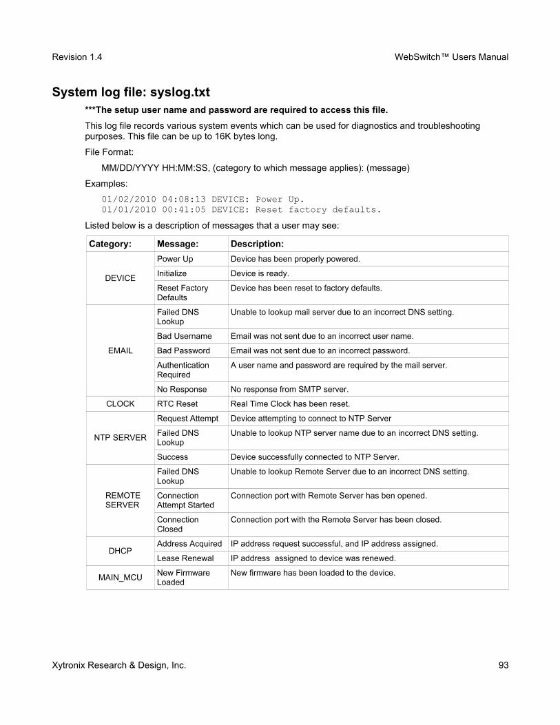
Revision 1.4 WebSwitch™ Users Manual
System log file: syslog.txt***The setup user name and password are required to access this file.
This log file records various system events which can be used for diagnostics and troubleshooting purposes. This file can be up to 16K bytes long.
File Format:
MM/DD/YYYY HH:MM:SS, (category to which message applies): (message)
Examples:
01/02/2010 04:08:13 DEVICE: Power Up.01/01/2010 00:41:05 DEVICE: Reset factory defaults.
Listed below is a description of messages that a user may see:
Category: Message: Description:
DEVICE
Power Up Device has been properly powered.
Initialize Device is ready.
Reset Factory Defaults
Device has been reset to factory defaults.
Failed DNS Lookup
Unable to lookup mail server due to an incorrect DNS setting.
Bad Username Email was not sent due to an incorrect user name.
Bad Password Email was not sent due to an incorrect password.
Authentication Required
A user name and password are required by the mail server.
No Response No response from SMTP server.
CLOCK RTC Reset Real Time Clock has been reset.
NTP SERVER
Request Attempt Device attempting to connect to NTP Server
Failed DNS Lookup
Unable to lookup NTP server name due to an incorrect DNS setting.
Success Device successfully connected to NTP Server.
REMOTE SERVER
Failed DNS Lookup
Unable to lookup Remote Server due to an incorrect DNS setting.
Connection Attempt Started
Connection port with Remote Server has ben opened.
Connection Closed
Connection port with the Remote Server has been closed.
DHCPAddress Acquired IP address request successful, and IP address assigned.
Lease Renewal IP address assigned to device was renewed.
MAIN_MCUNew Firmware Loaded
New firmware has been loaded to the device.
Xytronix Research & Design, Inc. 93

Revision 1.4 WebSwitch™ Users Manual
This file is read by requesting the syslog.txt file. For example, using the default IP address the following command would be used:
http://192.168.1.2/syslog.txt
If the TCP port has been changed (not port 80), the port will be required to read the file. For example, using the default IP address, and port 8000, the log file would be read as follows:
http://192.168.1.2:8000/syslog.txt
To erase the file, use:
http://192.168.1.2/syslog.txt?erase=1
Xytronix Research & Design, Inc. 94
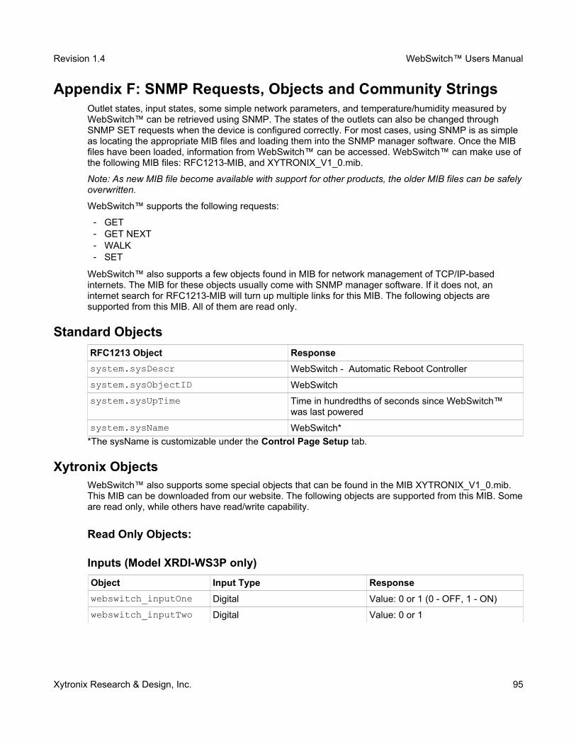
Revision 1.4 WebSwitch™ Users Manual
Appendix F: SNMP Requests, Objects and Community StringsOutlet states, input states, some simple network parameters, and temperature/humidity measured by WebSwitch™ can be retrieved using SNMP. The states of the outlets can also be changed through SNMP SET requests when the device is configured correctly. For most cases, using SNMP is as simple as locating the appropriate MIB files and loading them into the SNMP manager software. Once the MIB files have been loaded, information from WebSwitch™ can be accessed. WebSwitch™ can make use ofthe following MIB files: RFC1213-MIB, and XYTRONIX_V1_0.mib.
Note: As new MIB file become available with support for other products, the older MIB files can be safelyoverwritten.
WebSwitch™ supports the following requests:
━ GET ━ GET NEXT ━ WALK ━ SET
WebSwitch™ also supports a few objects found in MIB for network management of TCP/IP-based internets. The MIB for these objects usually come with SNMP manager software. If it does not, an internet search for RFC1213-MIB will turn up multiple links for this MIB. The following objects are supported from this MIB. All of them are read only.
Standard Objects
RFC1213 Object Response
system.sysDescr WebSwitch - Automatic Reboot Controller
system.sysObjectID WebSwitch
system.sysUpTime Time in hundredths of seconds since WebSwitch™ was last powered
system.sysName WebSwitch*
*The sysName is customizable under the Control Page Setup tab.
Xytronix ObjectsWebSwitch™ also supports some special objects that can be found in the MIB XYTRONIX_V1_0.mib. This MIB can be downloaded from our website. The following objects are supported from this MIB. Someare read only, while others have read/write capability.
Read Only Objects:
Inputs (Model XRDI-WS3P only)
Object Input Type Response
webswitch_inputOne Digital Value: 0 or 1 (0 - OFF, 1 - ON)
webswitch_inputTwo Digital Value: 0 or 1
Xytronix Research & Design, Inc. 95
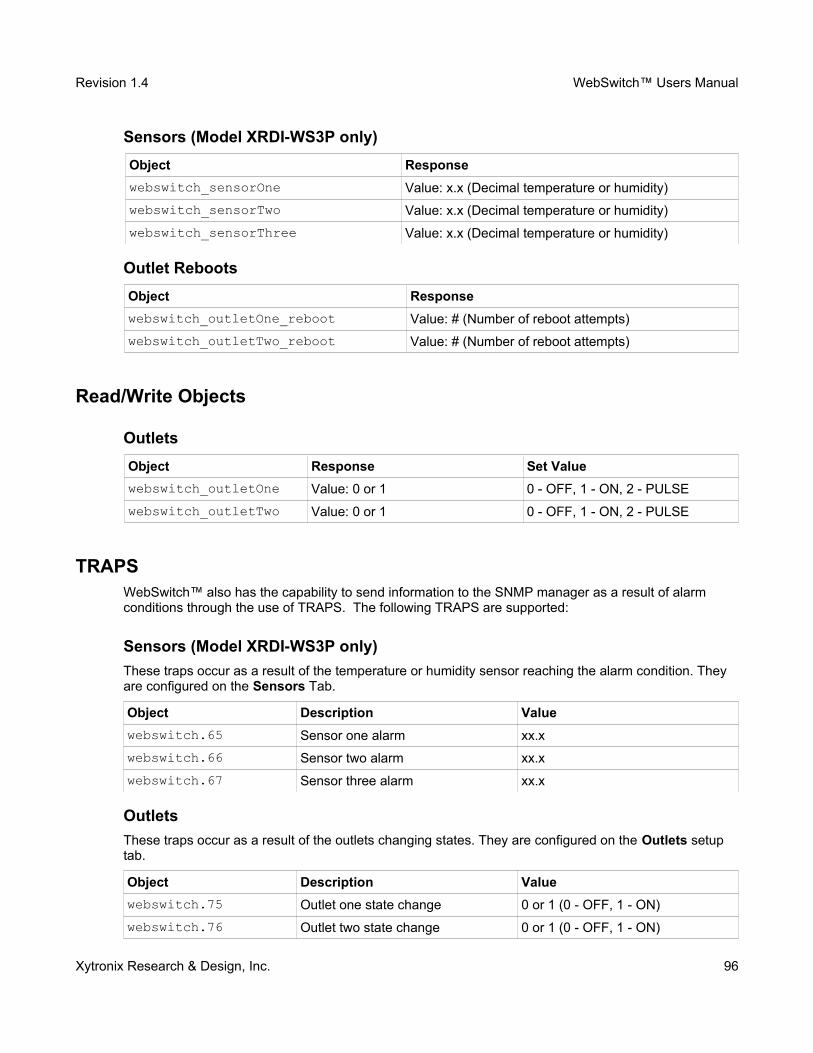
Revision 1.4 WebSwitch™ Users Manual
Sensors (Model XRDI-WS3P only)
Object Response
webswitch_sensorOne Value: x.x (Decimal temperature or humidity)
webswitch_sensorTwo Value: x.x (Decimal temperature or humidity)
webswitch_sensorThree Value: x.x (Decimal temperature or humidity)
Outlet Reboots
Object Response
webswitch_outletOne_reboot Value: # (Number of reboot attempts)
webswitch_outletTwo_reboot Value: # (Number of reboot attempts)
Read/Write Objects
Outlets
Object Response Set Value
webswitch_outletOne Value: 0 or 1 0 - OFF, 1 - ON, 2 - PULSE
webswitch_outletTwo Value: 0 or 1 0 - OFF, 1 - ON, 2 - PULSE
TRAPSWebSwitch™ also has the capability to send information to the SNMP manager as a result of alarm conditions through the use of TRAPS. The following TRAPS are supported:
Sensors (Model XRDI-WS3P only)
These traps occur as a result of the temperature or humidity sensor reaching the alarm condition. They are configured on the Sensors Tab.
Object Description Value
webswitch.65 Sensor one alarm xx.x
webswitch.66 Sensor two alarm xx.x
webswitch.67 Sensor three alarm xx.x
Outlets
These traps occur as a result of the outlets changing states. They are configured on the Outlets setup tab.
Object Description Value
webswitch.75 Outlet one state change 0 or 1 (0 - OFF, 1 - ON)
webswitch.76 Outlet two state change 0 or 1 (0 - OFF, 1 - ON)
Xytronix Research & Design, Inc. 96
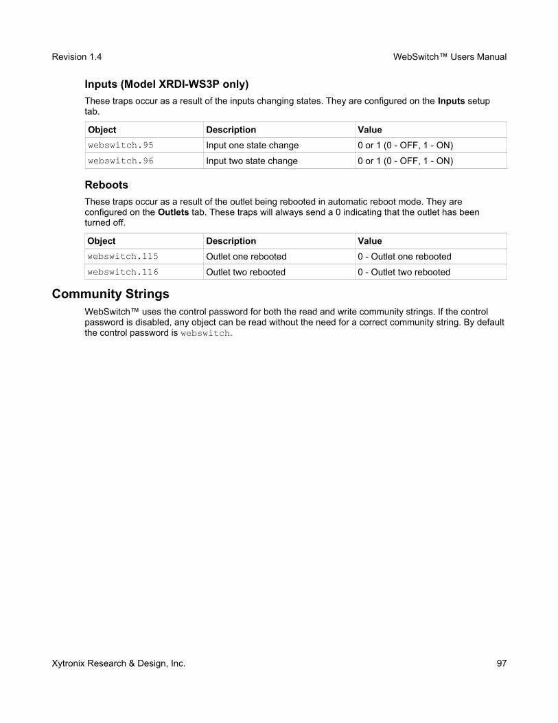
Revision 1.4 WebSwitch™ Users Manual
Inputs (Model XRDI-WS3P only)
These traps occur as a result of the inputs changing states. They are configured on the Inputs setup tab.
Object Description Value
webswitch.95 Input one state change 0 or 1 (0 - OFF, 1 - ON)
webswitch.96 Input two state change 0 or 1 (0 - OFF, 1 - ON)
Reboots
These traps occur as a result of the outlet being rebooted in automatic reboot mode. They are configured on the Outlets tab. These traps will always send a 0 indicating that the outlet has been turned off.
Object Description Value
webswitch.115 Outlet one rebooted 0 - Outlet one rebooted
webswitch.116 Outlet two rebooted 0 - Outlet two rebooted
Community StringsWebSwitch™ uses the control password for both the read and write community strings. If the control password is disabled, any object can be read without the need for a correct community string. By defaultthe control password is webswitch.
Xytronix Research & Design, Inc. 97
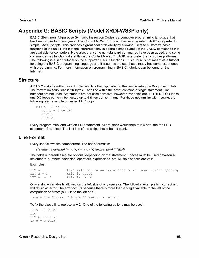
Revision 1.4 WebSwitch™ Users Manual
Appendix G: BASIC Scripts (Model XRDI-WS3P only)BASIC (Beginners All-purpose Symbolic Instruction Code) is a computer programming language that has been in use for many years. This ControlByWeb™ product has an integrated BASIC interpreter for simple BASIC scripts. This provides a great deal of flexibility by allowing users to customize basic functions of the unit. Note that the interpreter only supports a small subset of the BASIC commands that are available for computers. Note also, that some non-standard commands have been added, and somecommands may function differently on the ControlByWeb™ BASIC interpreter than on other platforms. The following is a short tutorial on the supported BASIC functions. This tutorial is not meant as a tutorial for using the BASIC programming language and it assumes the user has already had some experience with programming. For more information on programming in BASIC, tutorials can be found on the Internet.
StructureA BASIC script is written as a .txt file, which is then uploaded to the device using the Script setup tab. The maximum script size is 2K bytes. Each line within the script contains a single statement. Line numbers are not used. Statements are not case sensitive; however, variables are. IF THEN, FOR loops, and DO loops can only be nested up to 5 times per command. For those not familiar with nesting, the following is an example of nested FOR loops:
FOR a = 0 to 100 FOR b = 0 to 100NEXT bNEXT a
Every program must end with an END statement. Subroutines would then follow after the the END statement, if required. The last line of the script should be left blank.
Line FormatEvery line follows the same format. The basic format is:
statement (variable) (=, <, >, <=, >=, <>) (expression) (THEN)
The fields in parentheses are optional depending on the statement. Spaces must be used between all statements, numbers, variables, operators, expressions, etc. Multiple spaces are valid.
Examples:
LET a=1 'this will return an error because of insufficient spacingLET a = 1 'this is validLET a = 1 'this is valid
Only a single variable is allowed on the left side of any operator. The following example is incorrect and will return an error. The error occurs because there is more than a single variable to the left of the comparison operator (a + 2 is to the left of =).
IF a + 2 = 3 THEN 'this will return an error
To fix the above line, replace 'a + 2.' One of the following options may be used:
IF a = 1 THEN...or...LET b = a + 2IF b = 3 THEN
Xytronix Research & Design, Inc. 98
Revision 1.4 WebSwitch™ Users Manual
Supported StatementsThe following are the statements supported by the ControlByWeb™ BASIC interpreter, a short description of the statements, and their formats.
LET
The LET statement assigns a variable a value. The format is:
LET (variable) = (expression)
IF THEN, ELSE, END IF
The IF THEN statement tests the truth of a condition. The ELSE statement defines a second function if the condition is found false. In other words, if the condition is true, then a function is performed. If it is nottrue, a second function may be performed. The second function may or may not be necessary depending on the application. The IF THEN (ELSE) statement must always be followed with an END IF statement. The format is:
IF (variable) (=, <, >, <=, >=, <>) (expression) THEN(Function 1)
ELSE(Function 2)
END IFNote: In most BASIC interpreters, 'Function 1' (see above) may be placed after the THEN statement. This interpreter requires 'Function 1' to be put on the following line.
FOR TO, NEXT
The FOR TO statement loops a section of code a predefined number of times. The NEXT statement always follows the section of code to be looped. The format is:
FOR (variable) = (expression) TO (expression)(code to be looped)
NEXT (variable)
DO WHILE, LOOP
The DO WHILE statement loops a section of code while a condition is found true. The LOOP statement always follows the section of code to be looped. Note that if the condition is omitted, the code will be looped without end. The format is:
DO WHILE (variable) (=, <, >, <=, >=, <>) (expression)(code to be looped)
LOOP
Xytronix Research & Design, Inc. 99
Revision 1.4 WebSwitch™ Users Manual
LOG
The LOG statement causes the device to log data according to the settings specified under the Loggingsetup tab. Note that in order to log, logging must be enabled in the Logging setup tab. The format is:
LOG
The EMAIL statement causes the device to send an email. The format is:
EMAIL...or...EMAIL relayX...or...EMAIL inputX...or...EMAIL tempX
The first option (EMAIL) sends an email message to all email addresses listed under the Network tab.
The second option (EMAIL relayX, where relay represents the internal relay, and where X represents therelay number 1 or 2 ) sends an email message identical to the message that is sent when that relay changes state. The message indicates that the email was caused by the relay, and the message is only sent to the email addresses specified in the appropriate relay setup page under the Outlets tab.
EMAIL relay1
The third option (EMAIL inputX , where X represents the input number 1 or 2) sends an email message identical to the message that is sent when that input changes state. The message indicates that the email was caused by that input, and the message is only sent to the email addresses specified in the appropriate Input setup page under the Inputs tab.
EMAIL input1
The fourth option (EMAIL tempX, where X represents the sensor number 1-3) sends an email message identical to the message that is sent when that sensor's Alarm condition is reached. The message indicates that the email was caused by the temperature alarm being reached, and the message is only sent to the email addresses specified in the appropriate sensor setup page under the Sensors tab.
EMAIL temp1
END
The END statement ends the main body of code.
END
Xytronix Research & Design, Inc. 100
Revision 1.4 WebSwitch™ Users Manual
CALL
The CALL statement is found within the main body of code, but requires the interpreter to skip to a subroutine found at the end of the program. After the subroutine is finished, the interpreter returns to the line immediately following the CALL statement. The format is:
CALL (name of subroutine)
SUB, END SUB
The SUB statement defines the beginning and name of a subroutine. The END SUB statement defines the end of the respective subroutine. Subroutine names can be up to 20 characters long and are case sensitive. The SUB and END SUB statements always must follow the END statement. The format is:
ENDSUB (name of subroutine)
(contents of subroutine)END SUB
REM or '
The REM or ( ' ) statement designates remarks made by the programmer. The interpreter will disregard any characters following these statements.
The PRINT statement outlets a variable or message (if contained within quotation marks). Note that the PRINT statement is only available for the PC version of the BASIC interpreter. The device will not recognize the command. The format is:
PRINT (variable) 'outlet variable value to screenPRINT "(message)" 'outlet '(message)' to screen
VariablesTwo types of variables are available for use in the ControlByWeb™ BASIC interpreter - user-defined variables, and useful predefined variables.
User-Defined Variables
Up to 10 user-defined variables are allowed to be used in scripts. Variables are represented by single, lower-case characters ranging from the letter 'a' to the letter 'j' in the English alphabet. They are always global and stored internally as floating point numbers. Variables are defined using the LET statement.
Examples:Let b = 5 'variable b will be set to 5Let d = b + 2 'variable d will be set to 7
The following are useful predefined variables for the ControlByWeb™ BASIC interpreter. Note that somemodels may not contain digital inputs, analog inputs and/or relays and thus would not have digital input, analog input and/or relay variables.
Xytronix Research & Design, Inc. 101
Revision 1.4 WebSwitch™ Users Manual
Timer Variables
Six timers are available for use in BASIC scripts. They are designated as t0 through t5. Timers can be set to any positive integer (or 0) by using the LET statement. As soon as a value is assigned to a timer, itwill begin to count down immediately by decrementing one count every 100ms until it reaches zero.
Examples:Let t3 = 1500 'set timer 3 to 150 secondsLet t1 = 0 'disable time 1
Internal Relay Variables
The internal relays can be turned on, turned off, pulsed, toggled, or read in BASIC scripts. The LET statement is used to set the internal relay state. The state options available are 0 (turn outlet off), 1 (turn outlet on), 2 (pulse outlet), and 5 (toggle outlet). Note that the pulse time is specified in the Outlets setup tab. Internal relays are designated as relay1 and relay2, which correspond to Outlet1 and Outlet2.
Examples:Let relay1 = 1 'turn on relay 1Let relay2 = 0 'turn off relay 2Let relay1 = 2 'pulse relay 1Let relay2 = 5 'toggle relay 2Let a = relay2 'read the state of relay 2, state will be 0 or 1
Input Variables
The input states can be read in BASIC scripts. The inputs are designated as input1 and input2.
Example:Let a = input1 'sets 'a' equal to value of input 1
Temperature/Humidity Sensor Variables
Each temperature sensor can be read in BASIC scripts. The temperature sensors are designated as temp1, temp2, and temp3.
Example:If temp2 >= 80 Then 'If temperature sensor reads greater than 80
' degrees, thenLet relay2 = 1 'Turn on relay 2
End If
Xytronix Research & Design, Inc. 102
Revision 1.4 WebSwitch™ Users Manual
Event Variables
Actions can be configured to occur at specified days and times. Five events may be configured for the unit. This is done by setting the day and time of the event and then comparing it to the current date and time. Note that the current date and time must be set in the Date/Time setup tab. The event date variables are designated ed1 to ed5. They are set using the LET command and setting the desired eventdate variable equal to the date the event should occur in the format mm/dd/yyyy. The event time variables are designated et1 to et5. They are likewise set using the LET command and setting the corresponding event time variable equal to the event time in the format hh:mm:ss in 24-hour time. The event date variables store the number of days that have passed since January 1, 1970. The event time variables store the number of seconds from the beginning of the day. If the event time variable is incremented more than the number of seconds in a day (86400 seconds), the counter is reset to 0 and the event date variable is incremented by one. The variables 'time' and 'date' are predefined variables that store the current date and time and can only be read. They can then be used to compare the event date and times. The following example demonstrates defining the event variables and comparing it to the current date and time. Assume current time is April 10, 2009 at 1:30 AM and the event should occur in one hour and every hour thereafter.
Example:Let a = 1Let ed1 = 04/10/2009 'sets the event date to April 10,
'2009.Let et1 = 02:30:00 'sets the event time to 2:30Do While a <> 0If ed1 >= date Then 'Tests event date versus current date.
If et1 >= time Then 'Tests event time versus current time.Let et1 = et1 + 3600 'Increments the event time by one hour
'(in seconds).Print "Event" 'Event to occur
End IfEnd IfLoopEnd
External Variables
There are five external variables, extvar0 through extvar4. External variables are similar to general purpose variables and can be used in the same manner. The difference between general purpose variables and external variables is that external variables can be accessed by the user through a web browser and modified while the script is running. Scripts can use external variables as a method of retrieving user input. The following example demonstrates this by creating a script that will turn Outlet 1 on if extvar1 equals 1 and turn Outlet 1 off if extvar1 equals 0.
Example:
DoIf extvar1 = 1 Then
Let relay1 = 1Else
Let relay1 = 0End If
LoopEnd
Xytronix Research & Design, Inc. 103
Revision 1.4 WebSwitch™ Users Manual
Extvar1 can be set and cleared by entering the following requests into a web browser or by configuring on and off buttons to appear on the control page for extvar0:
http://192.168.1.2/state.xml?extvar1=1http://192.168.1.2/state.xml?extvar1=0
Testing and Debugging:
Note that a copy of the BASIC interpreter for Windows is also available on our website for the use of testing and debugging. The device will only acknowledge errors as it runs. This means that if a path of the script is not encountered, errors may still exist. The Windows version of the interpreter, however, will check for errors before the script is run. Note also that the PRINT function is available for use with the Windows version of the BASIC interpreter. The interpreter on the device, however, will not recognize thiscommand.
Note: The script will be restarted by submitting any of the setup pages or by power cycling the unit.
Xytronix Research & Design, Inc. 104
Revision 1.4 WebSwitch™ Users Manual
Appendix H: Specifications
Power Requirements:
━ Input Voltage: 100-240V AC━ Input Frequency: 47-63Hz━ Input Connector: IEC Appliance Connector (C14 Male)━ Max Input Current: 10A (DO NOT USE WEBSWITCH TO CONTROL MORE THAN 10 AMPS -
BOTH OUTLETS)
Outlets:
━ Number of Outlets: 2━ Outlet Connectors: IEC Appliance Connector (C13 Female)━ Outlet Control Options: On/Off or Pulse
Accessory Connector (Model XRDI-WS3P only):
━ 5-position, removable terminal strip, 3.81 mm terminal spacing
Inputs (Model XRDI-WS3P only):
━ Number of Inputs: 2 ━ Input Type: Discrete Inputs (connect to dry contacts)━ Maximum Input Voltage: 5 VDC━ Minimum Hold Time: 20ms
Temperature Sensors (Model XRDI-WS3P only):
━ “1-Wire” Digital Thermometer (Dallas Semiconductor part DS18B20)━ Temperature Range: -20°C to 40°C ( -4°F to 104°F)━ Accuracy: 0.5 from -10°C to +85°C━ Maximum number of sensors: 3 ━ Maximum Distance from WebSwitch™ to sensors: 120 feet with one sensor, 60 feet with three
sensors
Additional Sensors (Model XRDI-WS3P only):
━ Temperature/Humidity Sensor (X-DTHS-WM)━ Humidity Range: 0-100%━ Accuracy: ±1.8%
Network:
━ 10Base-T or 100Base-T Ethernet IPv4━ Setup: static IP address assignment or DHCP, HTTP port selectable━ Network Connector: 8-pin RJ-45 socket
LED Indicators:
━ Power On━ Outlet 1 On━ Outlet 2 On━ Network Linked━ Network Activity
Xytronix Research & Design, Inc. 105

Revision 1.4 WebSwitch™ Users Manual
Real-Time Clock (Model XRDI-WS3P only):
━ Manual or NTP (Network Time Protocol) setup━ NTP Sync Period: Once, Daily, Weekly, On Power-up━ Automatic Daylight Savings Adjustment━ Battery (capacitor) Power Backup
Capacitor Power Backup (Model XRDI-WS3P only):
━ Backup Functions: Retain Real-Time Clock, External Variables, Outlet State━ Backup Duration: 3 days minimum
Nonvolatile Memory:
━ Memory Type: Flash━ Function: All user settings are stored in nonvolatile memory. Settings will not be lost when power is
disconnected.
Physical:
━ Operating Temperature: -20° C to 40° C (-4° F to 104° F)━ Size: 10.65 Inches (27.11 cm) wide X 1.75 Inches (4.45 cm) tall X 3.29 Inches (8.36 cm) deep━ Tolerance: ±0.03 Inches━ Weight: 1 lb. 3 oz. (542 grams)━ Enclosure Material: Lexan 940 (UL94 V0 Flame Rated)
Monitor/Control:
━ Web Browser, XML, Modbus/TCP, SNMP
Logging (Model XRDI-WS3P only):
━ Storage: Nonvolatile Flash━ Buffer Architecture: Circular Buffer━ Log File Size: 512K (max 17272 logs)━ Unlimited data storage from Web Monitoring Service
Password Settings:
━ Password protection on setup page: Yes━ Password protection on control page: Optional━ Password Encoding: Base 64━ Max password length: 13 characters
Xytronix Research & Design, Inc. 106

Revision 1.4 WebSwitch™ Users Manual
Regulatory Compliance:
━ Electromagnetic Compliance:━ IEC CISPR 22, CISPR 24━ FCC 47CFR15━ EU EN55024, EN55022━ EN55022:2006: Class B━ EN61000-3-2━ EN61000-3-3━ EN55024:2006━ IEC 61000-4-2━ IEC 61000-4-3━ IEC 61000-4-4━ IEC 61000-4-5━ IEC 61000-4-6━ IEC 61000-4-8━ IEC 61000-4-11━ ITE-Class B
Product Safety:
IEC 60950-1 / EN 60950-1
Xytronix Research & Design, Inc. 107
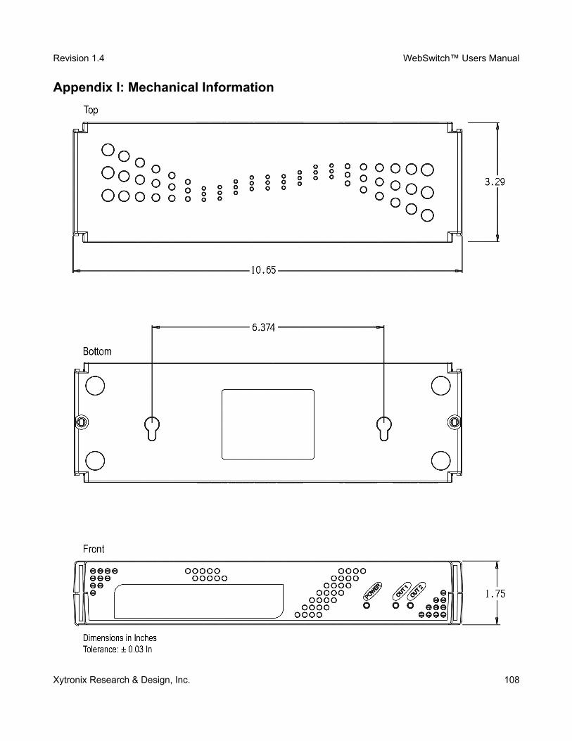
Revision 1.4 WebSwitch™ Users Manual
Appendix I: Mechanical Information
Xytronix Research & Design, Inc. 108