Embed Size (px)
Citation preview

WEB-BASED PROMISE ARRAY MANAGEMENT
(WEBPAM) USER MANUAL
Version 1.4

WebPAM User Manual
ii
Copyright © 2003 Promise Technology, Inc.
Copyright by Promise Technology, Inc. (Promise Technology). No part of this manual may be reproduced or transmitted in any form without the expressed, written permission of Promise Technology.
Trademarks Promise, and the Promise logo are registered in U.S. Patent and Trademark Office. All other product names mentioned herein may be trademarks or registered trademarks of their respective companies.
Important data protection information You should back up all data before installing any drive controller or storage peripheral. Promise Technology is not responsible for any loss of data resulting from the use, disuse or misuse of this or any other Promise Technology product.
Notice Although Promise Technology has attempted to ensure the accuracy of the content of this manual, it is possible that this document may contain technical inaccuracies, typographical, or other errors. Promise Technology assumes no liability for any error in this publication, and for damages, whether direct, indirect, incidental, consequential or otherwise, that may result from such error, including, but not limited to loss of data or profits.
Promise Technology provides this publication “as is” without warranty of any kind, either express or implied, including, but not limited to implied warranties of merchantability or fitness for a particular purpose.
The published information in the manual is subject to change without notice. Promise Technology reserves the right to make changes in the product design, layout, and driver revisions without notification to its users.
WebPAM User Manual
iii
Contents Chapter 1: Introduction ...................................................................................... 1
WebPAM Components ............................................................................... 1 How They Work Together........................................................................... 2 WebPAM Installation Options..................................................................... 3
Chapter 2: Installation ........................................................................................ 5 Installation Locations................................................................................... 5 Utility Server................................................................................................. 5 CIMOM Agent .............................................................................................. 6 Operating System Support ......................................................................... 7 Network Requirements ............................................................................... 7 Before you start… ....................................................................................... 7 Install WebPAM ........................................................................................... 8 WebPAM to UltraTrak Connections ......................................................... 16 Uninstalling WebPAM ............................................................................... 17
Chapter 3: Initial Setup .................................................................................... 19 Initial Log-in................................................................................................ 19
Regular Connection............................................................................ 20 Secure Connection ............................................................................. 20 Using a Hostname.............................................................................. 20
Create a New Host (RAID PC) ................................................................. 24 Create a New User.................................................................................... 25 Access a Host............................................................................................ 28 Create an Array ......................................................................................... 29 View Event Log.......................................................................................... 31 Logging Out ............................................................................................... 31
Chapter 4: WebPAM User Interface ............................................................... 33 Tree View................................................................................................... 34 Management Window ............................................................................... 34
Administration Tools........................................................................... 34 User Management .............................................................................. 35 Host Management .............................................................................. 35 Utility Configuration ............................................................................ 36 Host ..................................................................................................... 37 Controller............................................................................................. 37 Disk View............................................................................................. 38 Disk View Disks .................................................................................. 38 Array View........................................................................................... 38 Array .................................................................................................... 39 Array Disks.......................................................................................... 39
WebPAM User Manual
iv
Enclosure View ................................................................................... 39 Enclosure ............................................................................................ 40 Event Window..................................................................................... 40 Banner ................................................................................................. 41
Chapter 5: RAID Monitoring and Management with WebPAM..................... 45 Log-in/Log-out............................................................................................ 45
Regular Connection............................................................................ 45 Secure Connection ............................................................................. 46 Using a Hostname.............................................................................. 46 Log-out ................................................................................................ 49
Host Management ..................................................................................... 50 Create a New Host ............................................................................. 50 Host User Rights................................................................................. 51 Access a Host (RAID PC) .................................................................. 52 Host (RAID PC) Management Window............................................. 53 View Event Log................................................................................... 53 Delete a Host (RAID PC) ................................................................... 54
User Management..................................................................................... 55 Create a New User ............................................................................. 55 Delete a User ...................................................................................... 58 Manage User Rights........................................................................... 58 Setup Email Alert Notification ............................................................ 60
Array Management.................................................................................... 61 Create an Array .................................................................................. 61 Array Critical Status............................................................................ 63 Rebuild Array ...................................................................................... 64 Expand Array ...................................................................................... 65 Convert Array...................................................................................... 66 Synchronize Array .............................................................................. 68 Synchronization Schedule ................................................................. 68 Array Functions................................................................................... 70 Delete an Array................................................................................... 71
Controller Management ............................................................................ 72 Set / Release Lock ............................................................................. 75 Disk View............................................................................................. 76 Enclosure View ................................................................................... 77
Appendix A: RAID ............................................................................................ 79 RAID 0 - Striping........................................................................................ 79 RAID 1 - Mirroring ..................................................................................... 80 RAID 0+1 - Striping / Mirroring ................................................................. 80 RAID 3 - Block Striping with Parity Drive................................................. 81
WebPAM User Manual
v
RAID 5 - Block and Parity Striping ........................................................... 82 RAID 30 - Striping of Dedicated Parity Arrays ........................................ 83 RAID 50 - Striping of Distributed Parity Arrays ....................................... 83 JBOD - Single Drive .................................................................................. 84 Supported RAID Levels ............................................................................ 85 Number of Disk Drives .............................................................................. 85 RAID Level Conversion............................................................................. 86
Appendix B: Connection and Compatibility .................................................... 89 IP Address ................................................................................................. 89 DHCP Issues ............................................................................................. 90 Operating System Support ....................................................................... 90 Network Requirements ............................................................................. 90 Java Requirements ................................................................................... 91 Security Warnings ..................................................................................... 91 Selected Definitions .................................................................................. 92
Appendix C: Troubleshooting .......................................................................... 93 Why can’t I see my Machine/Host/RAID PC in WebPAM? .................... 93
First-time use of WebPAM................................................................. 93 WebPAM worked before but now it doesn’t...................................... 98

WebPAM User Manual
vi
1
Chapter 1: Introduction The Web-Based Promise Array Management Web (WebPAM) software is an application designed specifically for monitoring and managing Promise Technology RAID products. Promise includes RAID management utilities with many of its products, including:
• UltraTrak SX4000/SX8000
• UltraTrak RM4000/RM8000/RM15000
• SuperTrak 100/SX6000
Promise includes RAID management utilities with many of its products. But those utilities run on a personal computer with an internal RAID or one attached to it.
WebPAM, however, uses Web-Based Enterprise Management (WBEM) technology to run over a local area network or the internet to make possible secure RAID monitoring and management from any computer, using a standard Internet browser. This allows you to monitor your RAIDs from virtually any location and to take care of them over your network.
WebPAM Components There are three components to WebPAM:
Internet Browser – Netscape Navigator 6.0 or higher or Internet Explorer 5.0 or higher. The browser allows you to connect to the Utility Server through a network or Internet connection. The browser provides a Graphic User Interface (GUI) that reports on the condition of the RAID array.
The GUI receives and displays reports on RAID condition and operation through the Utility Server. From any location, including the Internet and your company intranet, you can perform RAID maintenance and corrective action. At your option, you may use Secure Sockets Layer (SSL) security over the Internet, within your intranet or both.
Utility Server – The Utility Server is the link connecting a Browser PC with the CIMOM Agent. Normally, the Utility Server runs on a network file server but it can also run on a networked PC. Its functions include maintaining the database and security. Only one Utility Server installation is required on your network.
WebPAM User Manual
2
CIMOM Agent – The CIMOM Agent runs on the PC that controls the RAID (RAID PC). It directly monitors the RAID and sends messages through the Utility Server to all connected browser PCs. CIMOM stands for Common Information Model (a protocol) Object Manager (server software that implements the protocol).
How They Work Together The Promise Array Management Web Utility (WebPAM) utility provides an easy way to set up, monitor and modify your RAID. Web PAM works with the Promise SuperTrak card and UltraTrak RAID subsystem.
WebPAM watches the RAID and when significant events happen, or it discovers a problem, the Agent sends a warning to the Utility Server. The Utility Server passes the warning along to all connected browser PCs.
Warnings appear on the PC in the form of email messages and popup alerts. You can select which events and problems PAM will report via email.
A major benefit of WebPAM is that it runs over the Internet. This enables remote monitoring and configuring of your RAIDs, across the room, across town or across the country.
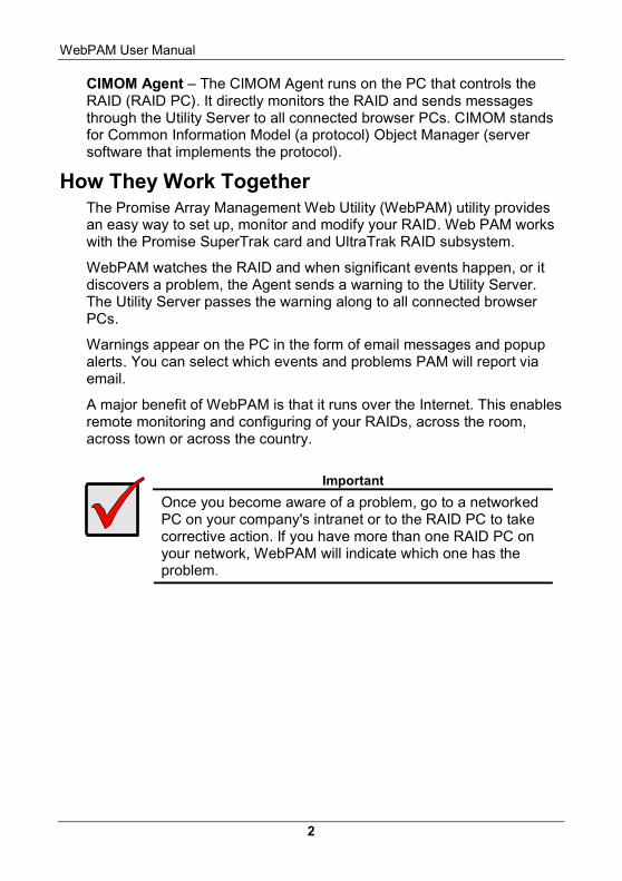
Important
Once you become aware of a problem, go to a networked PC on your company's intranet or to the RAID PC to take corrective action. If you have more than one RAID PC on your network, WebPAM will indicate which one has the problem.
Chapter 1: Introduction
3
WebPAM Installation Options Following are some examples of ways you can incorporate WebPAM into your network and RAID systems.
Router & Firewall
Laptop computer+
Internet browser
A networked PC+
Internet browser
Company LAN
Internet
Home-based PC+
Internet browser
Modem
Network File Server+
Utility Server
………………………………………………………………………………………………………………………………………………………………………………………………………………………………………………
PC with SuperTrak card& Internal RAID array
+CIMOM Agent
RAID PC withUltraTrak RAID Subsystem
+CIMOM Agent
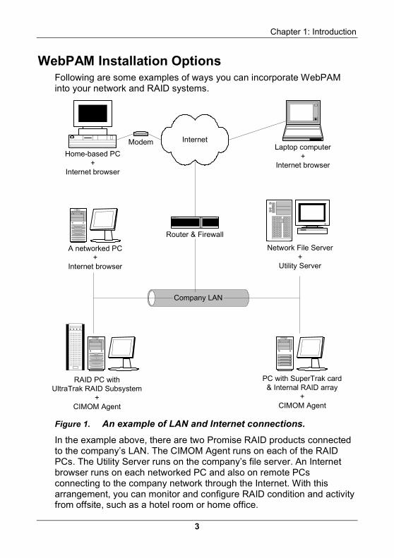
Figure 1. An example of LAN and Internet connections.
In the example above, there are two Promise RAID products connected to the company’s LAN. The CIMOM Agent runs on each of the RAID PCs. The Utility Server runs on the company’s file server. An Internet browser runs on each networked PC and also on remote PCs connecting to the company network through the Internet. With this arrangement, you can monitor and configure RAID condition and activity from offsite, such as a hotel room or home office.
WebPAM User Manual
4
A networked PC+
Internet browser
Company LAN
A networked PC+
Internet browser,Utility Server
………………………………………………………………………………………………………………………………………………………………………………………………………………………………………………
PC with SuperTrak card+
CIMOM Agent
RAID PC and UltraTrakRAID Subsystem
+CIMOM Agent
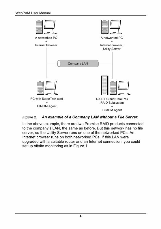
Figure 2. An example of a Company LAN without a File Server.
In the above example, there are two Promise RAID products connected to the company’s LAN, the same as before. But this network has no file server, so the Utility Server runs on one of the networked PCs. An Internet browser runs on both networked PCs. If this LAN were upgraded with a suitable router and an Internet connection, you could set up offsite monitoring as in Figure 1.
5
Chapter 2: Installation To install Web-Based Promise Array Management (WebPAM) software is an uncomplicated procedure, once you understand your systems and how you want to use WebPAM. The purpose of this Chapter is to help you plan and carry out your installation of WebPAM.
By way of review, WebPAM consists of two components:
• Utility Server
• CIMOM Agent
Although it does not come with the WebPAM software package, your Internet Browser provides the means for you to monitor and configure your Promise RAID products using WebPAM. You may use the most recent versions of either Internet Explorer or Netscape Navigator.
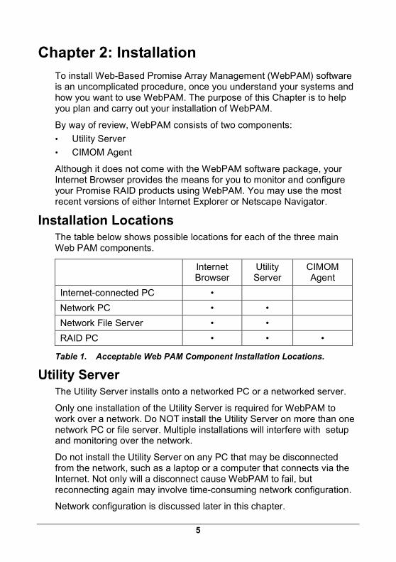
Installation Locations The table below shows possible locations for each of the three main Web PAM components.
Internet Browser
Utility Server
CIMOM Agent
Internet-connected PC •
Network PC • •
Network File Server • •
RAID PC • • •
Table 1. Acceptable Web PAM Component Installation Locations.
Utility Server The Utility Server installs onto a networked PC or a networked server.
Only one installation of the Utility Server is required for WebPAM to work over a network. Do NOT install the Utility Server on more than one network PC or file server. Multiple installations will interfere with setup and monitoring over the network.
Do not install the Utility Server on any PC that may be disconnected from the network, such as a laptop or a computer that connects via the Internet. Not only will a disconnect cause WebPAM to fail, but reconnecting again may involve time-consuming network configuration.
Network configuration is discussed later in this chapter.
WebPAM User Manual
6
Router & Firewall
Laptop computer+
Internet browser
A networked PC+
Internet browser
Company LAN
Internet
Home-based PC+
Internet browser
Modem
Network File Server+
Utility Server
………………………………………………………………………………………………………………………………………………………………………………………………………………………………………………
PC with SuperTrak card& Internal RAID array
+CIMOM Agent
RAID PC withUltraTrak RAID Subsystem
+CIMOM Agent
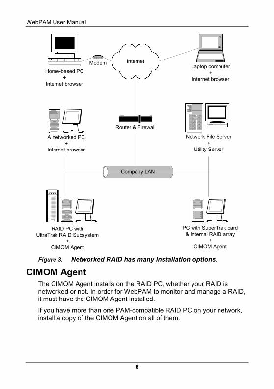
Figure 3. Networked RAID has many installation options.
CIMOM Agent The CIMOM Agent installs on the RAID PC, whether your RAID is networked or not. In order for WebPAM to monitor and manage a RAID, it must have the CIMOM Agent installed.
If you have more than one PAM-compatible RAID PC on your network, install a copy of the CIMOM Agent on all of them.
Chapter 2: Installation
7
Operating System Support WebPAM is a utility designed to run on top of previously installed SuperTrak and UltraTrak RAID products. Generally, if your PC runs the SuperTrak or UltraTrak properly, it will run WebPAM also. Note, however, that this version of WebPAM does not run on Linux.
Promise Technology recommends Windows NT 4.0, 2000 and XP Professional to take full advantage of all the features of WebPAM.
Network Requirements Since WebPAM is designed for network operation, be sure all the hosts and servers are connected and running. Each of the PCs, RAIDs and Servers must have a working network connection before you can configure WebPAM.
Before you start… If you are installing WebPAM to run over a network, obtain the IP addresses or Hostname of the PC where the Utility Server will be installed. See Appendix B for help in finding a PC’s IP Address and Hostname.
Important
If you currently have Promise Array Manager (Windows PAM) on your computer, completely remove it before installing WebPAM. Failure to do so will result in incompatibility problems.
WebPAM installs Java Runtime Environment (JRE) 1.4 on your system. If you currently have JRE or Java Development Kit (JDK) versions 1.2.2, 1.3.0 or 1.4, WebPAM will use the existing JRE rather than installing a second one.
If you are planning to use other applications that rely on JRE or JDK, always install JRE or JDK first before you install WebPAM. WebPAM will then detect the installed JRE or JDK.
For computers that will remotely monitor and manage the RAID, the Internet Browser is the only software required. Do not install other WebPAM components on these computers.
WebPAM User Manual
8
Install WebPAM With that information ready, follow these steps to install PAM on each computer or server:
1. Boot the PC/server and launch Windows.
If the computer is already running, exit all programs.
2. Insert WebPAM Install CD into your CD-ROM drive.
3. Double-click on the Install CD’s icon to open it.
4. Double-click on the Installer icon to launch it (right).
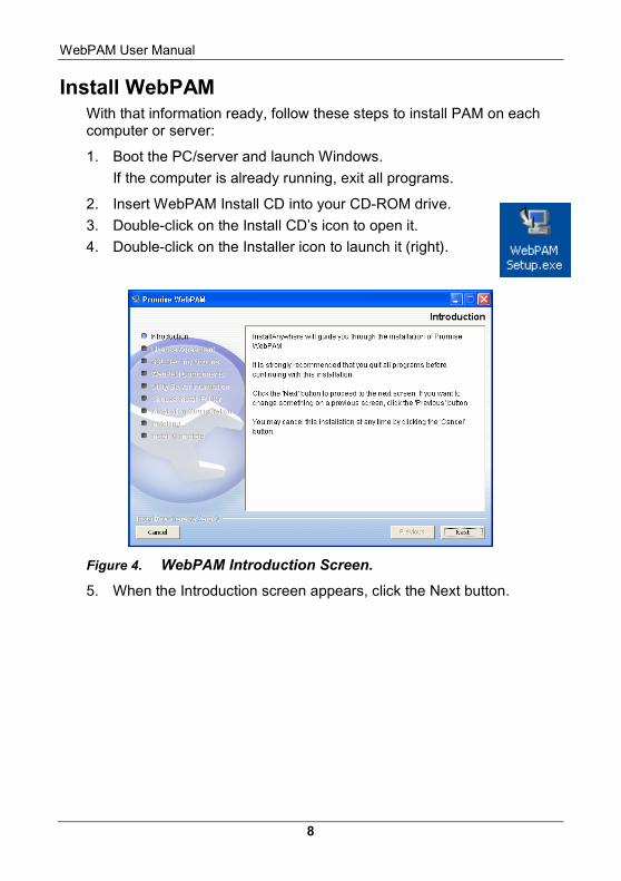
Figure 4. WebPAM Introduction Screen.
5. When the Introduction screen appears, click the Next button.
Chapter 2: Installation
9
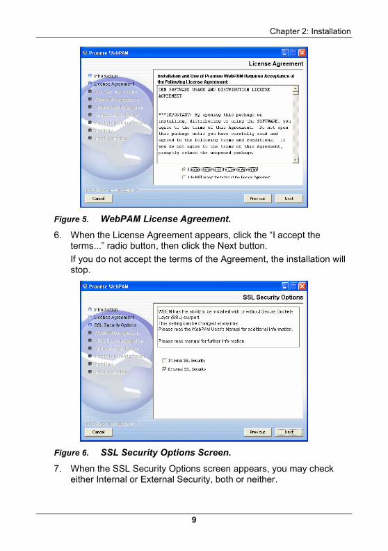
Figure 5. WebPAM License Agreement.
6. When the License Agreement appears, click the “I accept the terms...” radio button, then click the Next button.
If you do not accept the terms of the Agreement, the installation will stop.
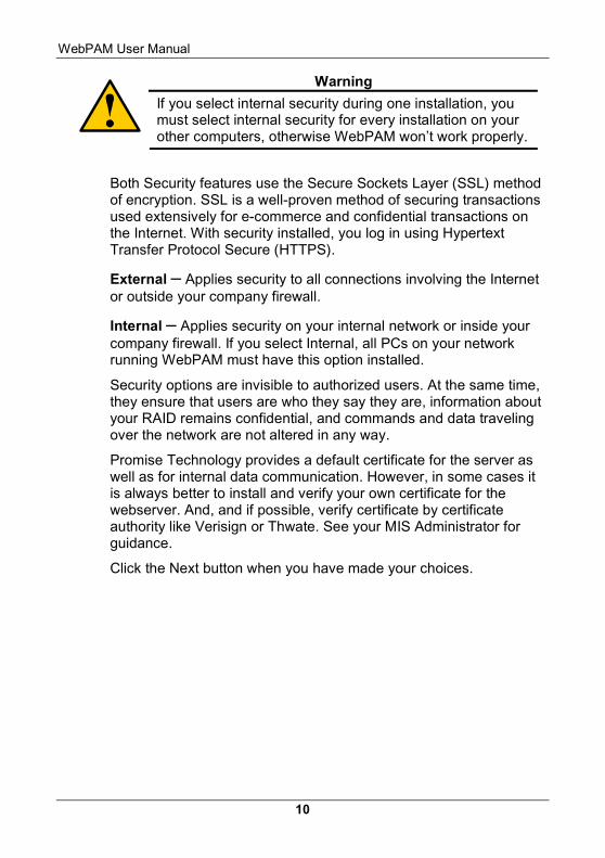
Figure 6. SSL Security Options Screen.
7. When the SSL Security Options screen appears, you may check either Internal or External Security, both or neither.
WebPAM User Manual
10
Warning
If you select internal security during one installation, you must select internal security for every installation on your other computers, otherwise WebPAM won’t work properly.
Both Security features use the Secure Sockets Layer (SSL) method of encryption. SSL is a well-proven method of securing transactions used extensively for e-commerce and confidential transactions on the Internet. With security installed, you log in using Hypertext Transfer Protocol Secure (HTTPS).
External – Applies security to all connections involving the Internet or outside your company firewall.
Internal – Applies security on your internal network or inside your company firewall. If you select Internal, all PCs on your network running WebPAM must have this option installed.
Security options are invisible to authorized users. At the same time, they ensure that users are who they say they are, information about your RAID remains confidential, and commands and data traveling over the network are not altered in any way.
Promise Technology provides a default certificate for the server as well as for internal data communication. However, in some cases it is always better to install and verify your own certificate for the webserver. And, and if possible, verify certificate by certificate authority like Verisign or Thwate. See your MIS Administrator for guidance.
Click the Next button when you have made your choices.
Chapter 2: Installation
11
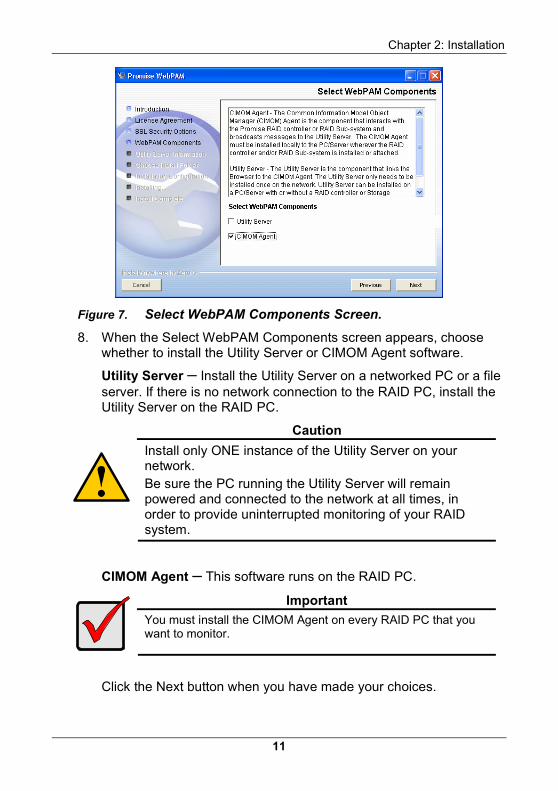
Figure 7. Select WebPAM Components Screen.
8. When the Select WebPAM Components screen appears, choose whether to install the Utility Server or CIMOM Agent software.
Utility Server – Install the Utility Server on a networked PC or a file server. If there is no network connection to the RAID PC, install the Utility Server on the RAID PC.
Caution
Install only ONE instance of the Utility Server on your network. Be sure the PC running the Utility Server will remain powered and connected to the network at all times, in order to provide uninterrupted monitoring of your RAID system.
CIMOM Agent – This software runs on the RAID PC.
Important
You must install the CIMOM Agent on every RAID PC that you want to monitor.
Click the Next button when you have made your choices.
WebPAM User Manual
12
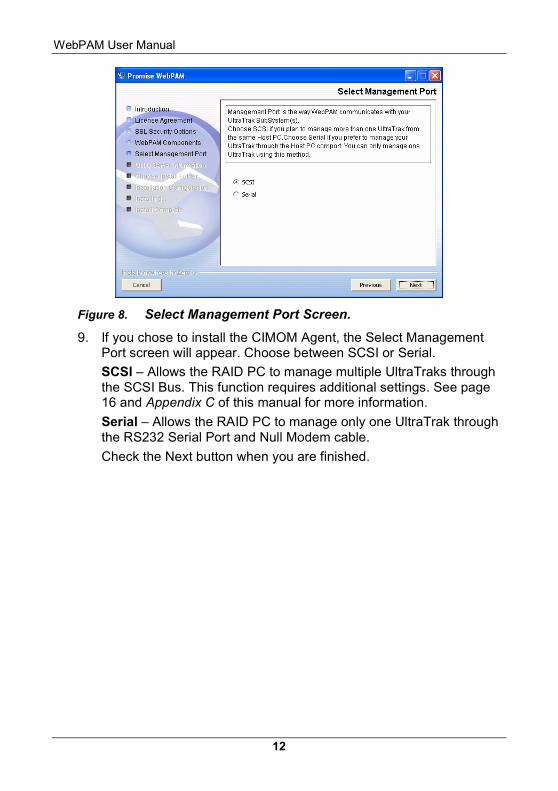
Figure 8. Select Management Port Screen.
9. If you chose to install the CIMOM Agent, the Select Management Port screen will appear. Choose between SCSI or Serial.
SCSI – Allows the RAID PC to manage multiple UltraTraks through the SCSI Bus. This function requires additional settings. See page 16 and Appendix C of this manual for more information.
Serial – Allows the RAID PC to manage only one UltraTrak through the RS232 Serial Port and Null Modem cable.
Check the Next button when you are finished.
Chapter 2: Installation
13
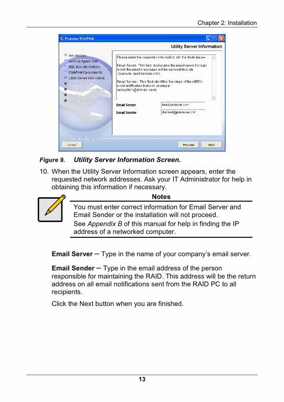
Figure 9. Utility Server Information Screen.
10. When the Utility Server Information screen appears, enter the requested network addresses. Ask your IT Administrator for help in obtaining this information if necessary.
Notes
You must enter correct information for Email Server and Email Sender or the installation will not proceed. See Appendix B of this manual for help in finding the IP address of a networked computer.
Email Server – Type in the name of your company’s email server.
Email Sender – Type in the email address of the person responsible for maintaining the RAID. This address will be the return address on all email notifications sent from the RAID PC to all recipients.
Click the Next button when you are finished.
WebPAM User Manual
14
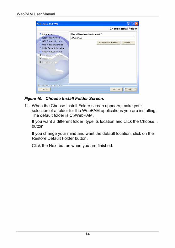
Figure 10. Choose Install Folder Screen.
11. When the Choose Install Folder screen appears, make your selection of a folder for the WebPAM applications you are installing. The default folder is C:\WebPAM.
If you want a different folder, type its location and click the Choose... button.
If you change your mind and want the default location, click on the Restore Default Folder button.
Click the Next button when you are finished.
Chapter 2: Installation
15
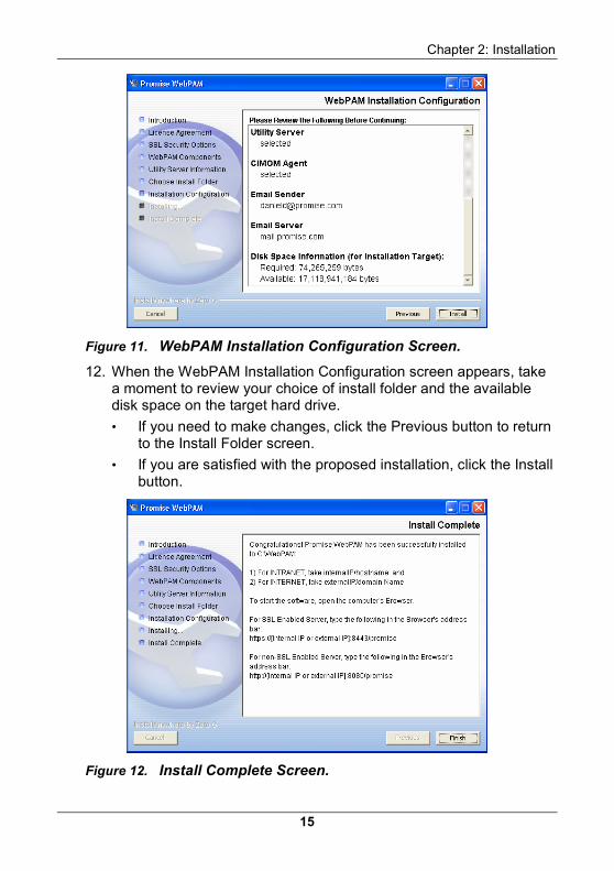
Figure 11. WebPAM Installation Configuration Screen.
12. When the WebPAM Installation Configuration screen appears, take a moment to review your choice of install folder and the available disk space on the target hard drive.
• If you need to make changes, click the Previous button to return to the Install Folder screen.
• If you are satisfied with the proposed installation, click the Install button.
Figure 12. Install Complete Screen.
WebPAM User Manual
16
When the Install Complete screen appears, the installation process is finished. Click the Finish button to go to the Promise Registration website.
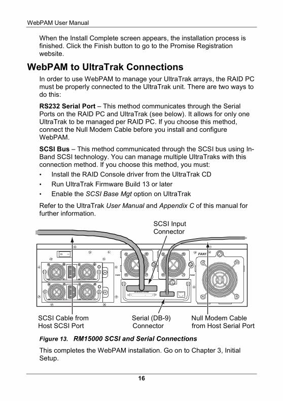
WebPAM to UltraTrak Connections In order to use WebPAM to manage your UltraTrak arrays, the RAID PC must be properly connected to the UltraTrak unit. There are two ways to do this:
RS232 Serial Port – This method communicates through the Serial Ports on the RAID PC and UltraTrak (see below). It allows for only one UltraTrak to be managed per RAID PC. If you choose this method, connect the Null Modem Cable before you install and configure WebPAM.
SCSI Bus – This method communicated through the SCSI bus using In-Band SCSI technology. You can manage multiple UltraTraks with this connection method. If you choose this method, you must:
• Install the RAID Console driver from the UltraTrak CD
• Run UltraTrak Firmware Build 13 or later
• Enable the SCSI Base Mgt option on UltraTrak
Refer to the UltraTrak User Manual and Appendix C of this manual for further information.
FAN1
FAN2FAN3
SCSI IOUT/TERM COM
SCSI IN
Figure 13. RM15000 SCSI and Serial Connections
This completes the WebPAM installation. Go on to Chapter 3, Initial Setup.
SCSI Cable from Serial (DB-9) Null Modem Cable Host SCSI Port Connector from Host Serial Port
SCSI Input Connector
Chapter 2: Installation
17
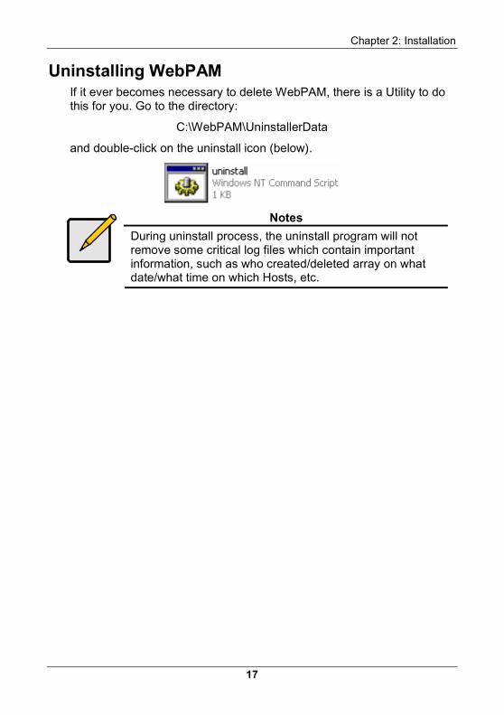
Uninstalling WebPAM If it ever becomes necessary to delete WebPAM, there is a Utility to do this for you. Go to the directory:
C:\WebPAM\UninstallerData
and double-click on the uninstall icon (below).
Notes
During uninstall process, the uninstall program will not remove some critical log files which contain important information, such as who created/deleted array on what date/what time on which Hosts, etc.

WebPAM User Manual
18
19
Chapter 3: Initial Setup After you have completed your WebPAM installation, you must setup Browser to work with your RAID.
Before you start, collect the IP addresses or Hostnames of the Utility Server PC and all of the RAID PCs.
Appendix B of this manual describes how to locate a PC’s hostname and IP address.
The first time you connect to the Utility Server, you must log in as the Administrator and type in the Administrator’s password. If this requirement presents a security concern, have the System Administrator perform the initial connections.
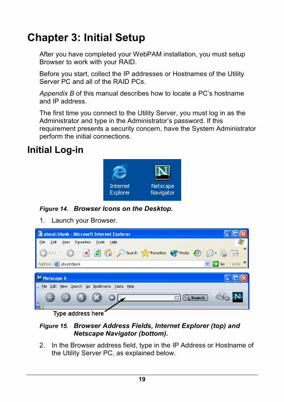
Initial Log-in
Figure 14. Browser Icons on the Desktop.
1. Launch your Browser.
Figure 15. Browser Address Fields, Internet Explorer (top) and Netscape Navigator (bottom).
2. In the Browser address field, type in the IP Address or Hostname of the Utility Server PC, as explained below.
WebPAM User Manual
20
Note: If your network has a DHCP server, Promise recommends that you specify the Hostname, rather than the IP Address, when creating a new Host (RAID PC). See Appendix B of this manual for more information.
Regular Connection • WebPAM uses an HTTP connection .......................http://
• Use either the IP Address .......................... 192.168.1.108
or Hostname ....................................................webserver1
• Indicate the Port number ........................................... :8080
• Add promise to launch WebPAM ......................../promise
Together, your entry looks like these:
http://192.168.1.108:8080/promise
http://webserver1:8080/promise
Note that when you are using an IP Address from an external connection, such as over the Internet, you will use a different IP Address than you would over the company’s LAN. See your MIS Administrator for help in establishing external access. This requirement applies to regular and secure connections.
Secure Connection If you installed a security option (see Chapter 2), use a secure login.
• WebPAM uses a secure HTTP connection ...........https://
• Use either the IP Address .......................... 192.168.1.108
or Hostname ....................................................webserver1
• Indicate the Port number ........................................... :8443
• Add promise to launch WebPAM ......................../promise
Together, your entry looks like these:
https://192.168.1.108:8443/promise
https://webserver1:8443/promise
Note that the IP Address and Hostname shown above are only examples. The IP Address and Hostname you type in will be different.
Using a Hostname In order to use a Hostname rather than an IP address, your network must have a Domain Name System (DNS) Server and the DNS Server
Chapter 3: Initial Setup
21
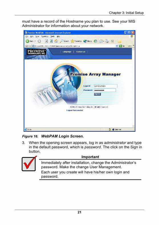
must have a record of the Hostname you plan to use. See your MIS Administrator for information about your network.
Figure 16. WebPAM Login Screen.
3. When the opening screen appears, log in as administrator and type in the default password, which is password. The click on the Sign in button.
Important
Immediately after installation, change the Administrator’s password. Make the change User Management. Each user you create will have his/her own login and password.
WebPAM User Manual
22
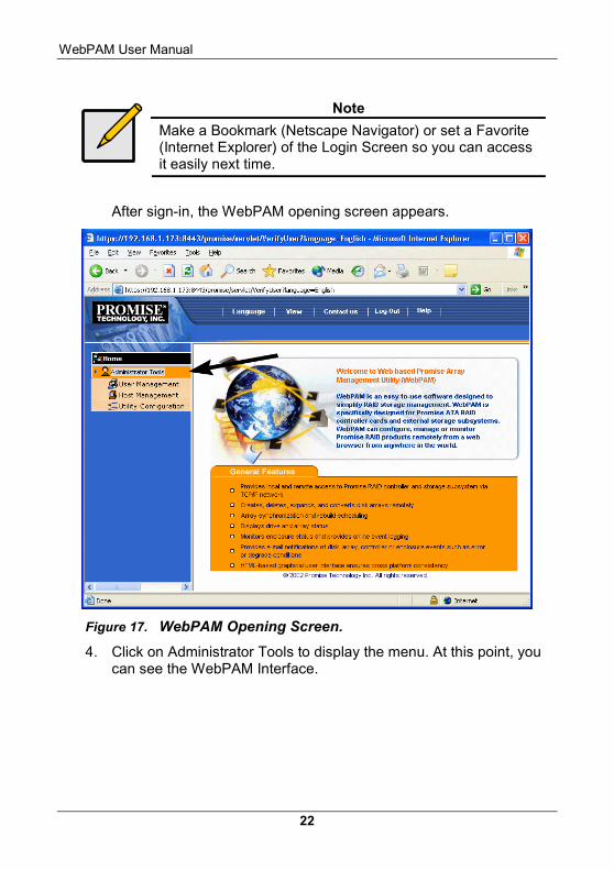
Note
Make a Bookmark (Netscape Navigator) or set a Favorite (Internet Explorer) of the Login Screen so you can access it easily next time.
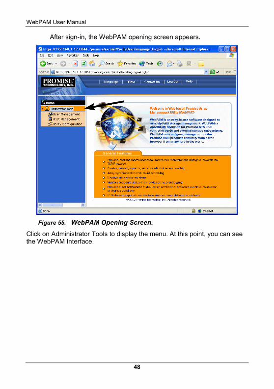
After sign-in, the WebPAM opening screen appears.
Figure 17. WebPAM Opening Screen.
4. Click on Administrator Tools to display the menu. At this point, you can see the WebPAM Interface.
Chapter 3: Initial Setup
23
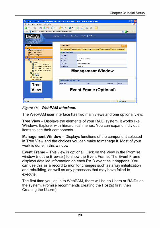
Figure 18. WebPAM Interface.
The WebPAM user interface has two main views and one optional view:
Tree View – Displays the elements of your RAID system. It works like Windows Explorer with hierarchical menus. You can expand individual items to see their components.
Management Window – Displays functions of the component selected in Tree View and the choices you can make to manage it. Most of your work is done in this window.
Event Frame – This view is optional. Click on the View in the Promise window (not the Browser) to show the Event Frame. The Event Frame displays detailed information on each RAID event as it happens. You can use this as a record to monitor changes such as array initialization and rebuilding, as well as any processes that may have failed to execute.
The first time you log in to WebPAM, there will be no Users or RAIDs on the system. Promise recommends creating the Host(s) first, then Creating the User(s).
WebPAM User Manual
24
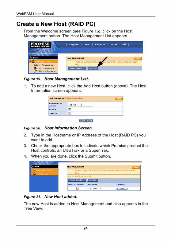
Create a New Host (RAID PC) From the Welcome screen (see Figure 16), click on the Host Management button. The Host Management List appears.
Figure 19. Host Management List.
1. To add a new Host, click the Add Host button (above). The Host Information screen appears.
Figure 20. Host Information Screen.
2. Type in the Hostname or IP Address of the Host (RAID PC) you want to add.
3. Check the appropriate box to indicate which Promise product the Host controls, an UltraTrak or a SuperTrak.
4. When you are done, click the Submit button.
Figure 21. New Host added.
The new Host is added to Host Management and also appears in the Tree View.
Chapter 3: Initial Setup
25
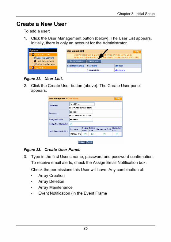
Create a New User To add a user:
1. Click the User Management button (below). The User List appears. Initially, there is only an account for the Administrator.
Figure 22. User List.
2. Click the Create User button (above). The Create User panel appears.
Figure 23. Create User Panel.
3. Type in the first User’s name, password and password confirmation.
To receive email alerts, check the Assign Email Notification box.
Check the permissions this User will have. Any combination of:
• Array Creation
• Array Deletion
• Array Maintenance
• Event Notification (in the Event Frame
WebPAM User Manual
26
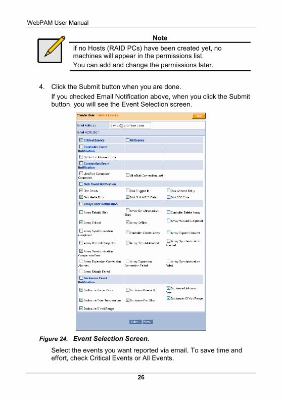
Note
If no Hosts (RAID PCs) have been created yet, no machines will appear in the permissions list. You can add and change the permissions later.
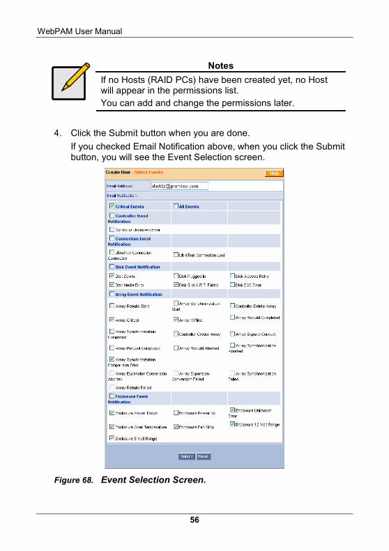
4. Click the Submit button when you are done.
If you checked Email Notification above, when you click the Submit button, you will see the Event Selection screen.
Figure 24. Event Selection Screen.
Select the events you want reported via email. To save time and effort, check Critical Events or All Events.
Chapter 3: Initial Setup
27
The Critical Events include:
• Disk Down • Disk Media Error • Disk SMART Failed • Array Critical • Array Synchronization
Compare Error • Array Offline
• Enclosure Power Down • Enclosure Over
Temperature • Enclosure 5 Volt Range • Enclosure Fan Stop • Enclosure Unknown Error • Enclosure 12 Volt Range
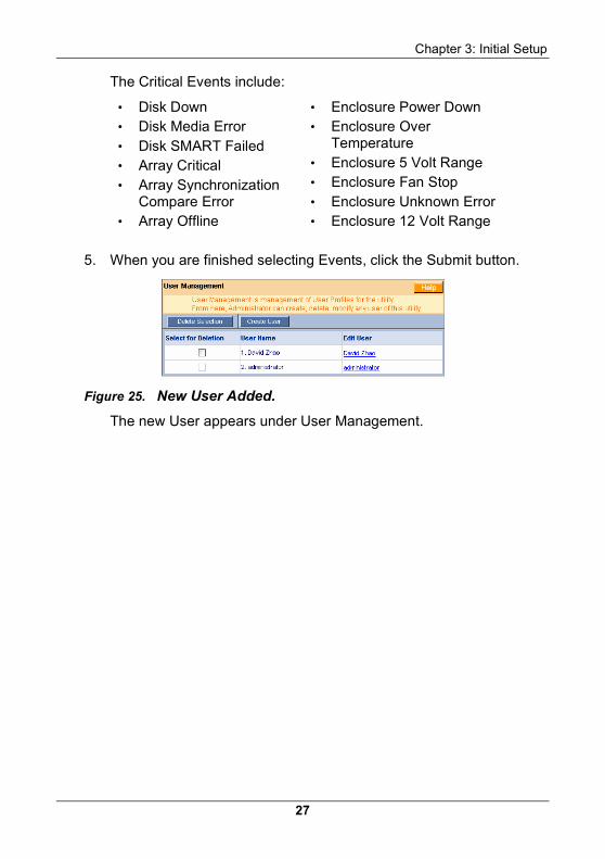
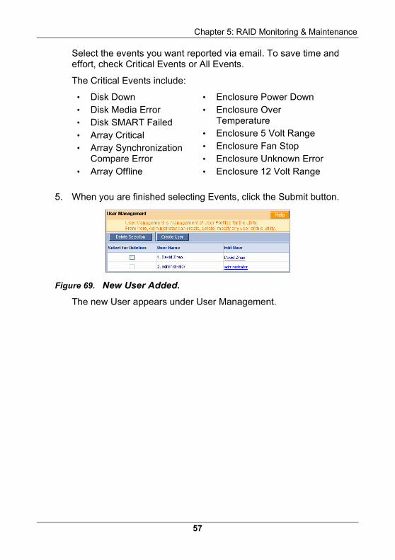
5. When you are finished selecting Events, click the Submit button.
Figure 25. New User Added.
The new User appears under User Management.
WebPAM User Manual
28
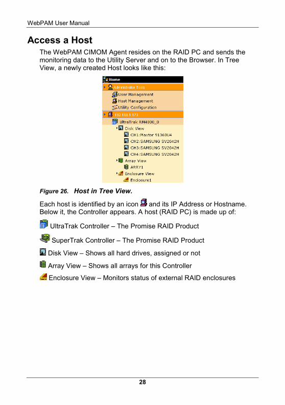
Access a Host The WebPAM CIMOM Agent resides on the RAID PC and sends the monitoring data to the Utility Server and on to the Browser. In Tree View, a newly created Host looks like this:
Figure 26. Host in Tree View.
Each host is identified by an icon and its IP Address or Hostname. Below it, the Controller appears. A host (RAID PC) is made up of:
UltraTrak Controller – The Promise RAID Product
SuperTrak Controller – The Promise RAID Product
Disk View – Shows all hard drives, assigned or not
Array View – Shows all arrays for this Controller
Enclosure View – Monitors status of external RAID enclosures
Chapter 3: Initial Setup
29
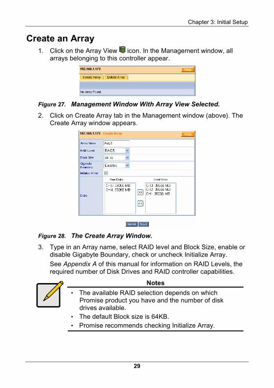
Create an Array 1. Click on the Array View icon. In the Management window, all
arrays belonging to this controller appear.
Figure 27. Management Window With Array View Selected.
2. Click on Create Array tab in the Management window (above). The Create Array window appears.
Figure 28. The Create Array Window.
3. Type in an Array name, select RAID level and Block Size, enable or disable Gigabyte Boundary, check or uncheck Initialize Array.
See Appendix A of this manual for information on RAID Levels, the required number of Disk Drives and RAID controller capabilities.
Notes
• The available RAID selection depends on which Promise product you have and the number of disk drives available.
• The default Block size is 64KB. • Promise recommends checking Initialize Array.
WebPAM User Manual
30
4. Select the Free Disks you want to use and click the >> button or double-click on the disks to move them to the Used Disks field.
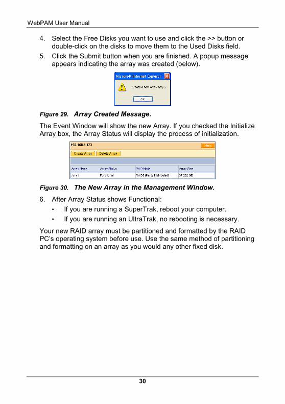
5. Click the Submit button when you are finished. A popup message appears indicating the array was created (below).
Figure 29. Array Created Message.
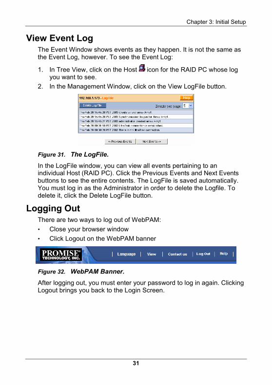
The Event Window will show the new Array. If you checked the Initialize Array box, the Array Status will display the process of initialization.
Figure 30. The New Array in the Management Window.
6. After Array Status shows Functional:
• If you are running a SuperTrak, reboot your computer.
• If you are running an UltraTrak, no rebooting is necessary.
Your new RAID array must be partitioned and formatted by the RAID PC’s operating system before use. Use the same method of partitioning and formatting on an array as you would any other fixed disk.
Chapter 3: Initial Setup
31
View Event Log The Event Window shows events as they happen. It is not the same as the Event Log, however. To see the Event Log:
1. In Tree View, click on the Host icon for the RAID PC whose log you want to see.
2. In the Management Window, click on the View LogFile button.
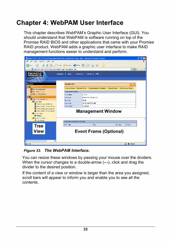
Figure 31. The LogFile.
In the LogFile window, you can view all events pertaining to an individual Host (RAID PC). Click the Previous Events and Next Events buttons to see the entire contents. The LogFile is saved automatically. You must log in as the Administrator in order to delete the Logfile. To delete it, click the Delete LogFile button.
Logging Out There are two ways to log out of WebPAM:
• Close your browser window
• Click Logout on the WebPAM banner
Figure 32. WebPAM Banner.
After logging out, you must enter your password to log in again. Clicking Logout brings you back to the Login Screen.

WebPAM User Manual
32
33
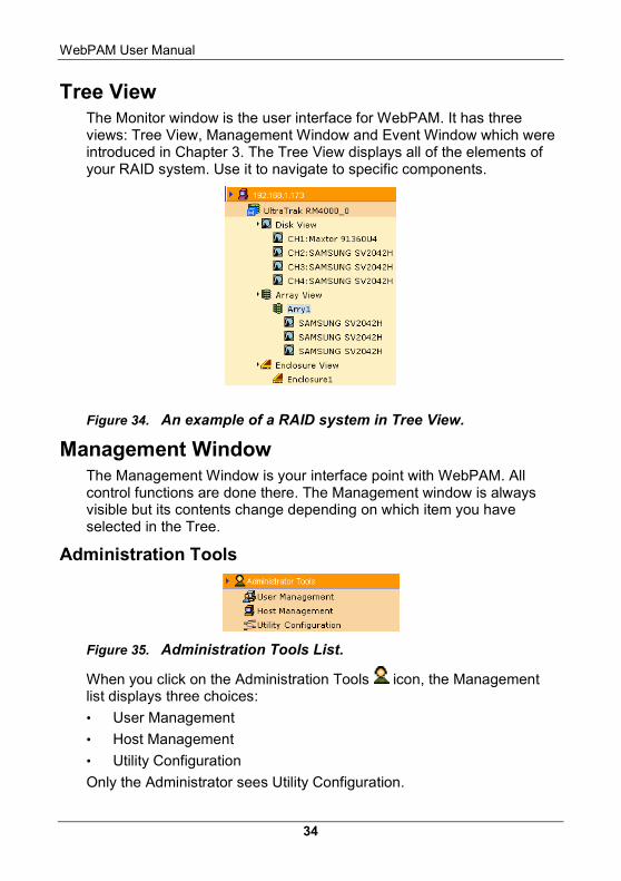
Chapter 4: WebPAM User Interface This chapter describes WebPAM’s Graphic User Interface (GUI). You should understand that WebPAM is software running on top of the Promise RAID BIOS and other applications that came with your Promise RAID product. WebPAM adds a graphic user interface to make RAID management functions easier to understand and perform.
Figure 33. The WebPAM Interface.
You can resize these windows by passing your mouse over the dividers. When the cursor changes to a double-arrow (↔), click and drag the divider to the desired position.
If the content of a view or window is larger than the area you assigned, scroll bars will appear to inform you and enable you to see all the contents.
WebPAM User Manual
34
Tree View The Monitor window is the user interface for WebPAM. It has three views: Tree View, Management Window and Event Window which were introduced in Chapter 3. The Tree View displays all of the elements of your RAID system. Use it to navigate to specific components.
Figure 34. An example of a RAID system in Tree View.
Management Window The Management Window is your interface point with WebPAM. All control functions are done there. The Management window is always visible but its contents change depending on which item you have selected in the Tree.
Administration Tools
Figure 35. Administration Tools List.
When you click on the Administration Tools icon, the Management list displays three choices:
• User Management
• Host Management
• Utility Configuration
Only the Administrator sees Utility Configuration.
Chapter 4: User Interface
35
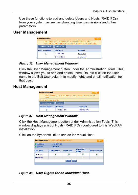
Use these functions to add and delete Users and Hosts (RAID PCs) from your system, as well as changing User permissions and other parameters.
User Management
Figure 36. User Management Window.
Click the User Management button under the Administration Tools. This window allows you to add and delete users. Double-click on the user name in the Edit User column to modify rights and email notification for that user.
Host Management
Figure 37. Host Management Window.
Click the Host Management button under Administration Tools. This window displays a list of Hosts (RAID PCs) configured to this WebPAM installation.
Click on the hypertext link to see an individual Host.
Figure 38. User Rights for an individual Host.
WebPAM User Manual
36
This window provides access information on an individual Host (RAID PC) and editing user permissions.
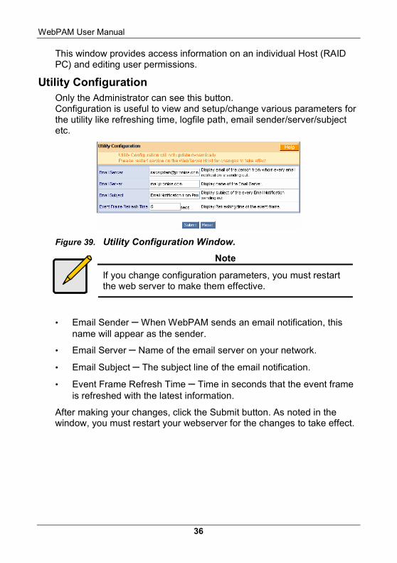
Utility Configuration Only the Administrator can see this button. Configuration is useful to view and setup/change various parameters for the utility like refreshing time, logfile path, email sender/server/subject etc.
Figure 39. Utility Configuration Window.
Note
If you change configuration parameters, you must restart the web server to make them effective.
• Email Sender – When WebPAM sends an email notification, this name will appear as the sender.
• Email Server – Name of the email server on your network.
• Email Subject – The subject line of the email notification.
• Event Frame Refresh Time – Time in seconds that the event frame is refreshed with the latest information.
After making your changes, click the Submit button. As noted in the window, you must restart your webserver for the changes to take effect.
Chapter 4: User Interface
37
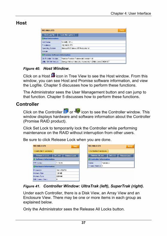
Host
Figure 40. Host Window.
Click on a Host icon in Tree View to see the Host window. From this window, you can see Host and Promise software information, and view the Logfile. Chapter 5 discusses how to perform these functions.
The Administrator sees the User Management button and can jump to that function. Chapter 5 discusses how to perform these functions.
Controller Click on the Controller or icon to see the Controller window. This window displays hardware and software information about the Controller (Promise RAID product).
Click Set Lock to temporarily lock the Controller while performing maintenance on the RAID without interruption from other users.
Be sure to click Release Lock when you are done.
Figure 41. Controller Window: UltraTrak (left), SuperTrak (right).
Under each Controller, there is a Disk View, an Array View and an Enclosure View. There may be one or more items in each group as explained below.
Only the Administrator sees the Release All Locks button.
WebPAM User Manual
38
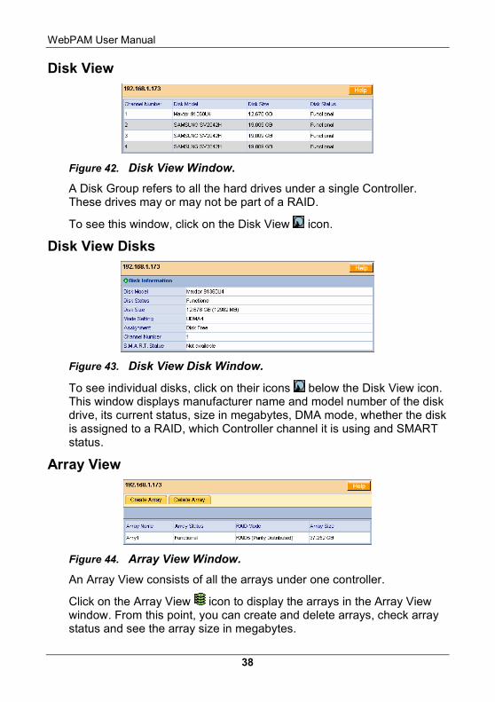
Disk View
Figure 42. Disk View Window.
A Disk Group refers to all the hard drives under a single Controller. These drives may or may not be part of a RAID.
To see this window, click on the Disk View icon.
Disk View Disks
Figure 43. Disk View Disk Window.
To see individual disks, click on their icons below the Disk View icon. This window displays manufacturer name and model number of the disk drive, its current status, size in megabytes, DMA mode, whether the disk is assigned to a RAID, which Controller channel it is using and SMART status.
Array View
Figure 44. Array View Window.
An Array View consists of all the arrays under one controller.
Click on the Array View icon to display the arrays in the Array View window. From this point, you can create and delete arrays, check array status and see the array size in megabytes.
Chapter 4: User Interface
39
Array
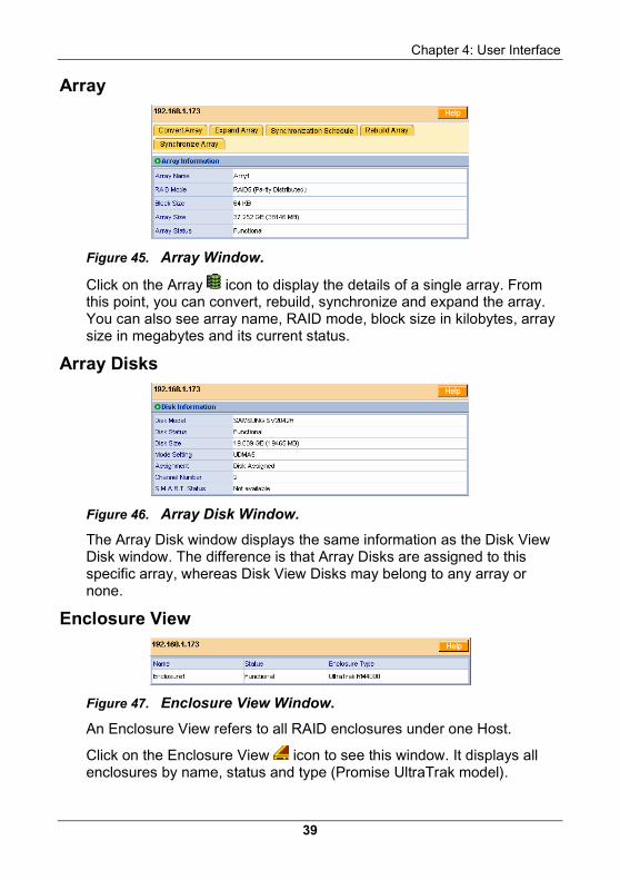
Figure 45. Array Window.
Click on the Array icon to display the details of a single array. From this point, you can convert, rebuild, synchronize and expand the array. You can also see array name, RAID mode, block size in kilobytes, array size in megabytes and its current status.
Array Disks
Figure 46. Array Disk Window.
The Array Disk window displays the same information as the Disk View Disk window. The difference is that Array Disks are assigned to this specific array, whereas Disk View Disks may belong to any array or none.
Enclosure View
Figure 47. Enclosure View Window.
An Enclosure View refers to all RAID enclosures under one Host.
Click on the Enclosure View icon to see this window. It displays all enclosures by name, status and type (Promise UltraTrak model).
WebPAM User Manual
40
Enclosure
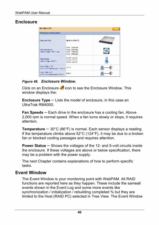
Figure 48. Enclosure Window.
Click on an Enclosure icon to see the Enclosure Window. This window displays the:
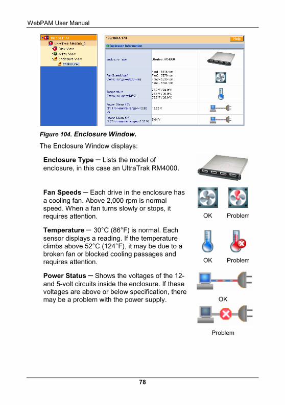
Enclosure Type – Lists the model of enclosure, in this case an UltraTrak RM4000.
Fan Speeds – Each drive in the enclosure has a cooling fan. Above 2,000 rpm is normal speed. When a fan turns slowly or stops, it requires attention.
Temperature – 30°C (86°F) is normal. Each sensor displays a reading. If the temperature climbs above 52°C (124°F), it may be due to a broken fan or blocked cooling passages and requires attention.
Power Status – Shows the voltages of the 12- and 5-volt circuits inside the enclosure. If these voltages are above or below specification, there may be a problem with the power supply.
The next Chapter contains explanations of how to perform specific tasks.
Event Window The Event Window is your monitoring point with WebPAM. All RAID functions are reported here as they happen. These include the sameall events shown in the Event Log and some more events like synchronization / initialization / rebuilding completed % but they are limited to the Host (RAID PC) selected in Tree View. The Event Window
Chapter 4: User Interface
41
is especially helpful in verifying that your commands are accepted and watching the progress of each operation.
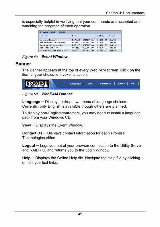
Figure 49. Event Window.
Banner The Banner appears at the top of every WebPAM screen. Click on the item of your choice to invoke its action.
Figure 50. WebPAM Banner.
Language – Displays a dropdown menu of language choices. Currently, only English is available though others are planned.
To display non-English characters, you may need to install a language pack from your Windows CD.
View – Displays the Event Window.
Contact Us – Displays contact information for each Promise Technologies office.
Logout – Logs you out of your browser connection to the Utility Server and RAID PC, and returns you to the Login Window.
Help – Displays the Online Help file. Navigate the Help file by clicking on its hypertext links.
WebPAM User Manual
42
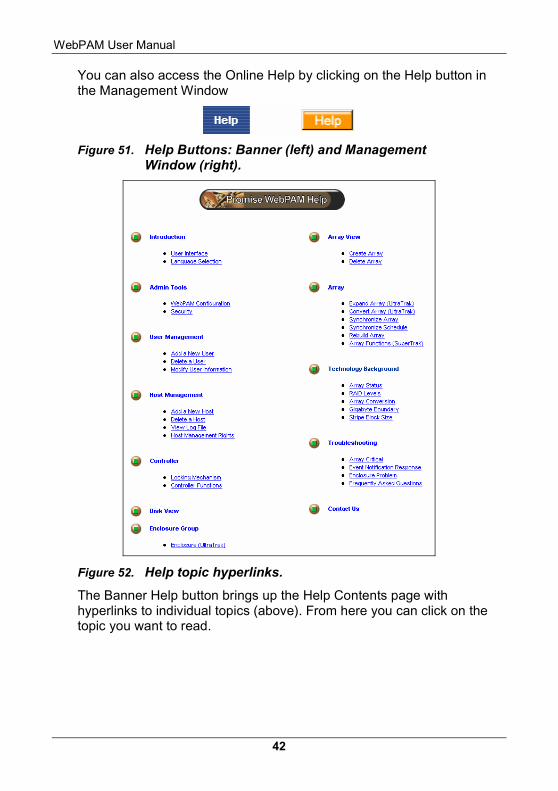
You can also access the Online Help by clicking on the Help button in the Management Window
Figure 51. Help Buttons: Banner (left) and Management Window (right).
Figure 52. Help topic hyperlinks.
The Banner Help button brings up the Help Contents page with hyperlinks to individual topics (above). From here you can click on the topic you want to read.
Chapter 4: User Interface
43
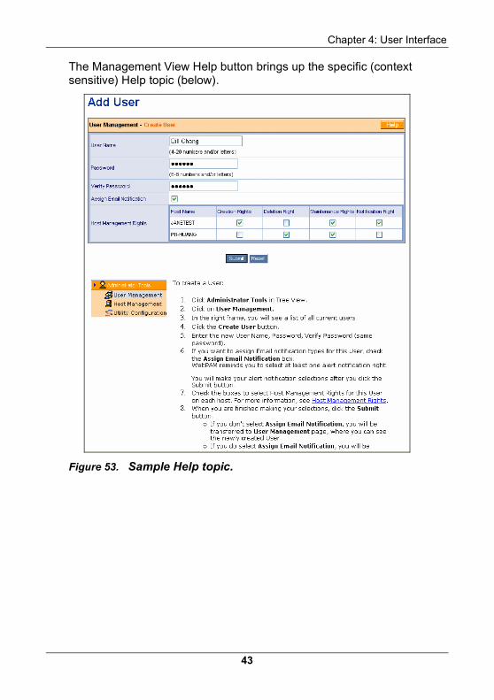
The Management View Help button brings up the specific (context sensitive) Help topic (below).
Figure 53. Sample Help topic.

WebPAM User Manual
44
45
Chapter 5: RAID Monitoring and Management with WebPAM
This chapter describes using WebPAM to monitor and manage your RAID system. The chapter is divided into sections for major WebPAM components:
• Log-in/Log-out
• Host (RAID PC) Management
• User Management
• Array Management
• Controller Management
• Disk Management
• Enclosure Management
Log-in/Log-out Log-in Over Network or Internet
1. Launch your Browser.
2. In the Browser address field, type in the IP Address or Hostname of the Utility Server PC, as explained below.
Note
If your network has a DHCP server, Promise recommends that you specify the Hostname, rather than the IP Address, when creating a new Host (RAID PC). See Appendix B for more information on DHCP servers.
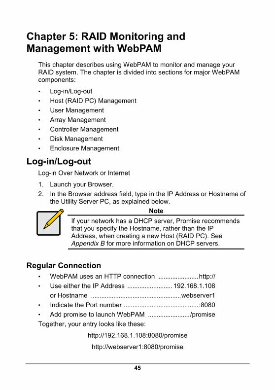
Regular Connection • WebPAM uses an HTTP connection .......................http://
• Use either the IP Address .......................... 192.168.1.108
or Hostname ....................................................webserver1
• Indicate the Port number ........................................... :8080
• Add promise to launch WebPAM ......................../promise
Together, your entry looks like these:
http://192.168.1.108:8080/promise
http://webserver1:8080/promise
WebPAM User Manual
46
Note that when you are using an IP Address from an external connection, such as over the Internet, you will use a different IP Address than you would over the company’s LAN. See your MIS Administrator for help in establishing external access. This requirement applies to regular and secure connections.
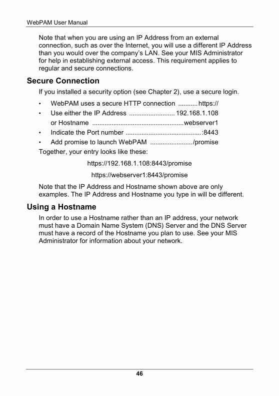
Secure Connection If you installed a security option (see Chapter 2), use a secure login.
• WebPAM uses a secure HTTP connection ...........https://
• Use either the IP Address .......................... 192.168.1.108
or Hostname ....................................................webserver1
• Indicate the Port number ........................................... :8443
• Add promise to launch WebPAM ......................../promise
Together, your entry looks like these:
https://192.168.1.108:8443/promise
https://webserver1:8443/promise
Note that the IP Address and Hostname shown above are only examples. The IP Address and Hostname you type in will be different.
Using a Hostname In order to use a Hostname rather than an IP address, your network must have a Domain Name System (DNS) Server and the DNS Server must have a record of the Hostname you plan to use. See your MIS Administrator for information about your network.
Chapter 5: RAID Monitoring & Maintenance
47
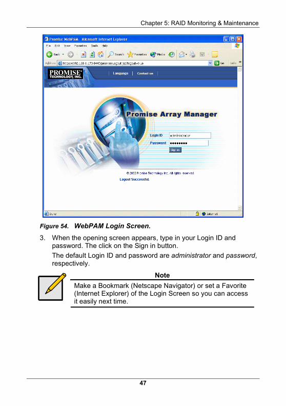
Figure 54. WebPAM Login Screen.
3. When the opening screen appears, type in your Login ID and password. The click on the Sign in button.
The default Login ID and password are administrator and password, respectively.
Note
Make a Bookmark (Netscape Navigator) or set a Favorite (Internet Explorer) of the Login Screen so you can access it easily next time.
WebPAM User Manual
48
After sign-in, the WebPAM opening screen appears.
Figure 55. WebPAM Opening Screen.
Click on Administrator Tools to display the menu. At this point, you can see the WebPAM Interface.
Chapter 5: RAID Monitoring & Maintenance
49
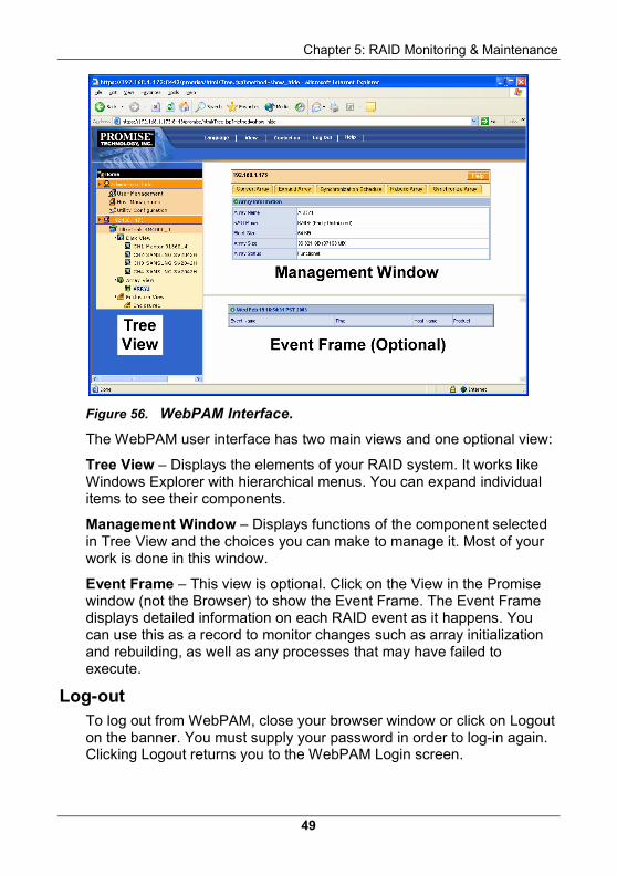
Figure 56. WebPAM Interface.
The WebPAM user interface has two main views and one optional view:
Tree View – Displays the elements of your RAID system. It works like Windows Explorer with hierarchical menus. You can expand individual items to see their components.
Management Window – Displays functions of the component selected in Tree View and the choices you can make to manage it. Most of your work is done in this window.
Event Frame – This view is optional. Click on the View in the Promise window (not the Browser) to show the Event Frame. The Event Frame displays detailed information on each RAID event as it happens. You can use this as a record to monitor changes such as array initialization and rebuilding, as well as any processes that may have failed to execute.
Log-out To log out from WebPAM, close your browser window or click on Logout on the banner. You must supply your password in order to log-in again. Clicking Logout returns you to the WebPAM Login screen.
WebPAM User Manual
50
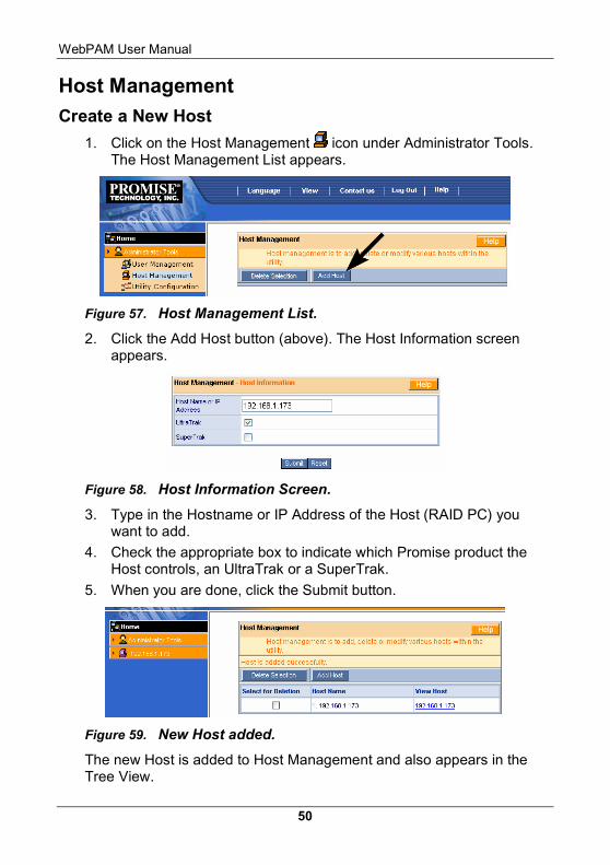
Host Management Create a New Host
1. Click on the Host Management icon under Administrator Tools. The Host Management List appears.
Figure 57. Host Management List.
2. Click the Add Host button (above). The Host Information screen appears.
Figure 58. Host Information Screen.
3. Type in the Hostname or IP Address of the Host (RAID PC) you want to add.
4. Check the appropriate box to indicate which Promise product the Host controls, an UltraTrak or a SuperTrak.
5. When you are done, click the Submit button.
Figure 59. New Host added.
The new Host is added to Host Management and also appears in the Tree View.
Chapter 5: RAID Monitoring & Maintenance
51
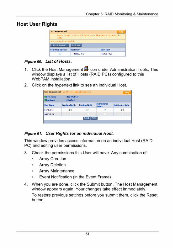
Host User Rights
Figure 60. List of Hosts.
1. Click the Host Management icon under Administration Tools. This window displays a list of Hosts (RAID PCs) configured to this WebPAM installation.
2. Click on the hypertext link to see an individual Host.
Figure 61. User Rights for an individual Host.
This window provides access information on an individual Host (RAID PC) and editing user permissions.
3. Check the permissions this User will have. Any combination of:
• Array Creation
• Array Deletion
• Array Maintenance
• Event Notification (in the Event Frame)
4. When you are done, click the Submit button. The Host Management window appears again. Your changes take effect immediately.
To restore previous settings before you submit them, click the Reset button.
WebPAM User Manual
52
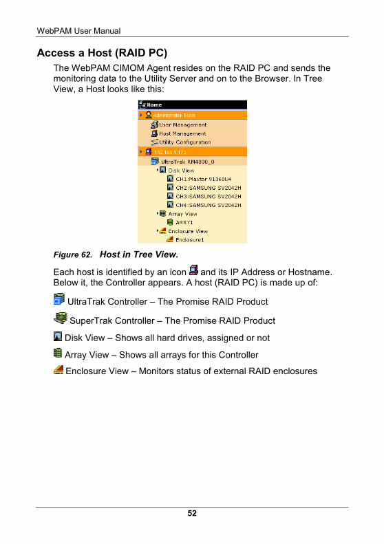
Access a Host (RAID PC) The WebPAM CIMOM Agent resides on the RAID PC and sends the monitoring data to the Utility Server and on to the Browser. In Tree View, a Host looks like this:
Figure 62. Host in Tree View.
Each host is identified by an icon and its IP Address or Hostname. Below it, the Controller appears. A host (RAID PC) is made up of:
UltraTrak Controller – The Promise RAID Product
SuperTrak Controller – The Promise RAID Product
Disk View – Shows all hard drives, assigned or not
Array View – Shows all arrays for this Controller
Enclosure View – Monitors status of external RAID enclosures
Chapter 5: RAID Monitoring & Maintenance
53
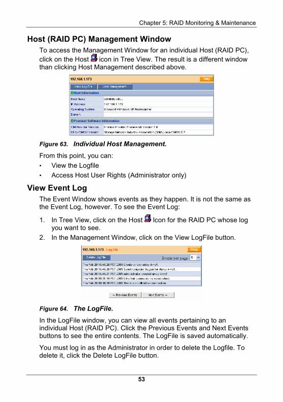
Host (RAID PC) Management Window To access the Management Window for an individual Host (RAID PC), click on the Host icon in Tree View. The result is a different window than clicking Host Management described above.
Figure 63. Individual Host Management.
From this point, you can:
• View the Logfile
• Access Host User Rights (Administrator only)
View Event Log The Event Window shows events as they happen. It is not the same as the Event Log, however. To see the Event Log:
1. In Tree View, click on the Host Icon for the RAID PC whose log you want to see.
2. In the Management Window, click on the View LogFile button.
Figure 64. The LogFile.
In the LogFile window, you can view all events pertaining to an individual Host (RAID PC). Click the Previous Events and Next Events buttons to see the entire contents. The LogFile is saved automatically.
You must log in as the Administrator in order to delete the Logfile. To delete it, click the Delete LogFile button.
WebPAM User Manual
54
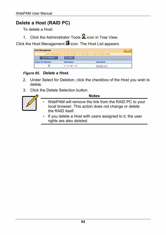
Delete a Host (RAID PC) To delete a Host:
1. Click the Administrator Tools icon in Tree View.
Click the Host Management icon. The Host List appears.
Figure 65. Delete a Host.
2. Under Select for Deletion, click the checkbox of the Host you wish to delete.
3. Click the Delete Selection button.
Notes
• WebPAM will remove the link from the RAID PC to your local browser. This action does not change or delete the RAID itself.
• If you delete a Host with users assigned to it, the user rights are also deleted.
Chapter 5: RAID Monitoring & Maintenance
55
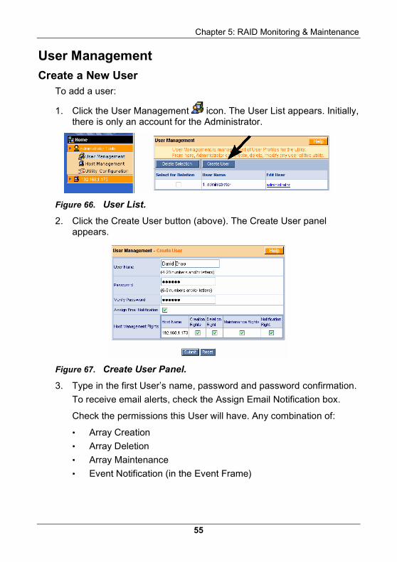
User Management Create a New User
To add a user:
1. Click the User Management icon. The User List appears. Initially, there is only an account for the Administrator.
Figure 66. User List.
2. Click the Create User button (above). The Create User panel appears.
Figure 67. Create User Panel.
3. Type in the first User’s name, password and password confirmation.
To receive email alerts, check the Assign Email Notification box.
Check the permissions this User will have. Any combination of:
• Array Creation
• Array Deletion
• Array Maintenance
• Event Notification (in the Event Frame)
WebPAM User Manual
56
Notes
If no Hosts (RAID PCs) have been created yet, no Host will appear in the permissions list. You can add and change the permissions later.
4. Click the Submit button when you are done.
If you checked Email Notification above, when you click the Submit button, you will see the Event Selection screen.
Figure 68. Event Selection Screen.
Chapter 5: RAID Monitoring & Maintenance
57
Select the events you want reported via email. To save time and effort, check Critical Events or All Events.
The Critical Events include:
• Disk Down • Disk Media Error • Disk SMART Failed • Array Critical • Array Synchronization
Compare Error • Array Offline
• Enclosure Power Down • Enclosure Over
Temperature • Enclosure 5 Volt Range • Enclosure Fan Stop • Enclosure Unknown Error • Enclosure 12 Volt Range
5. When you are finished selecting Events, click the Submit button.
Figure 69. New User Added.
The new User appears under User Management.
WebPAM User Manual
58
Delete a User To delete a User:
1. Click the Administrator Tools icon in Tree View.
2. Click the User Management icon. The User List appears.
Figure 70. Delete a User.
3. Click the checkbox of the User you wish to delete.
4. Click the Delete Selection button.
Notes
WebPAM will maintain at least one user with full access, typically the Administrator. This action prevents you from being locked out of the application and having to reload it.
Manage User Rights You setup User Rights for each Host (RAID PC) and each User individually. A Machine must be created before you can setup User Rights for it.
1. Click the Administrator Tools icon in Tree View.
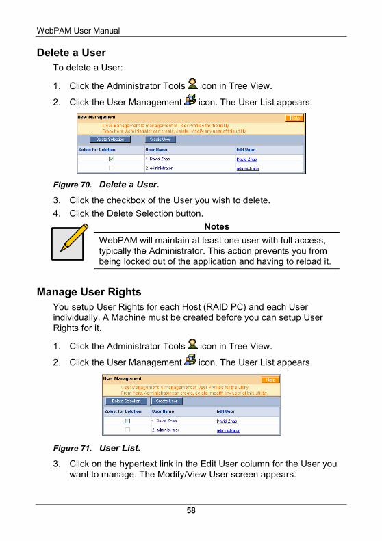
2. Click the User Management icon. The User List appears.
Figure 71. User List.
3. Click on the hypertext link in the Edit User column for the User you want to manage. The Modify/View User screen appears.
Chapter 5: RAID Monitoring & Maintenance
59
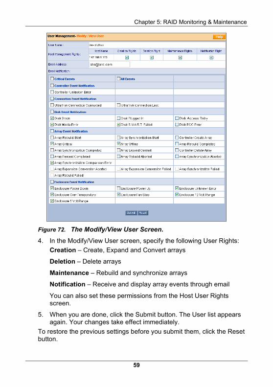
Figure 72. The Modify/View User Screen.
4. In the Modify/View User screen, specify the following User Rights:
Creation – Create, Expand and Convert arrays
Deletion – Delete arrays
Maintenance – Rebuild and synchronize arrays
Notification – Receive and display array events through email
You can also set these permissions from the Host User Rights screen.
5. When you are done, click the Submit button. The User list appears again. Your changes take effect immediately.
To restore the previous settings before you submit them, click the Reset button.
WebPAM User Manual
60
Setup Email Alert Notification WebPAM can alert you to the problems and processes happening to your RAID through email messages. You setup Email Notification for each Machine (RAID PC) and each User individually. A Machine must be created before you can setup Email Notification for it.
Note: You can also setup email alert notification during creation of user alsowhen you create a new User.
These steps describe how to setup the email function.
1. Click the Administrator Tools icon in Tree View.
2. Click the User Management icon. The User List appears (see Figure 69, above).
3. Click on the link in the Edit User column for the User you want to manage. The User Management screen appears (see Figure 70, above).
4. Enter the email address if this user will receive email notifications.
5. Select the notification items this user should receive via email. To select all the items in a category, click the checkbox in the category header.
6. When you are done, click the Submit button. The User list appears again. Your changes take effect immediately.
To restore the previous settings before you submit them, click the Reset button.
Chapter 5: RAID Monitoring & Maintenance
61
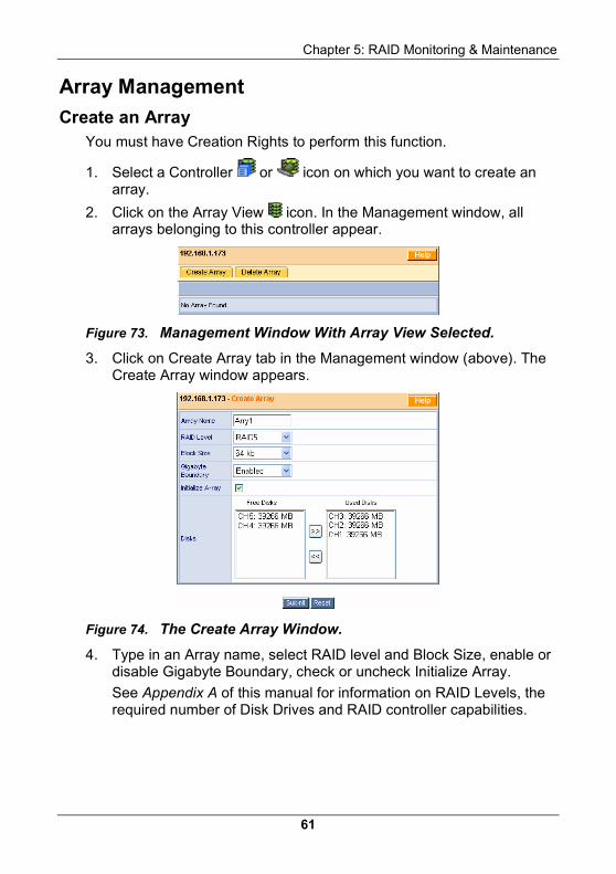
Array Management Create an Array
You must have Creation Rights to perform this function.
1. Select a Controller or icon on which you want to create an array.
2. Click on the Array View icon. In the Management window, all arrays belonging to this controller appear.
Figure 73. Management Window With Array View Selected.
3. Click on Create Array tab in the Management window (above). The Create Array window appears.
Figure 74. The Create Array Window.
4. Type in an Array name, select RAID level and Block Size, enable or disable Gigabyte Boundary, check or uncheck Initialize Array.
See Appendix A of this manual for information on RAID Levels, the required number of Disk Drives and RAID controller capabilities.
WebPAM User Manual
62
Notes
• The available RAID selection depends on which Promise product you have and the number of disk drives available.
• The default Block size is 64KB. • Promise recommends checking Initialize Array.
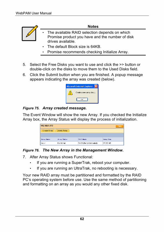
5. Select the Free Disks you want to use and click the >> button or double-click on the disks to move them to the Used Disks field.
6. Click the Submit button when you are finished. A popup message appears indicating the array was created (below).
Figure 75. Array created message.
The Event Window will show the new Array. If you checked the Initialize Array box, the Array Status will display the process of initialization.
Figure 76. The New Array in the Management Window.
7. After Array Status shows Functional:
• If you are running a SuperTrak, reboot your computer.
• If you are running an UltraTrak, no rebooting is necessary.
Your new RAID array must be partitioned and formatted by the RAID PC’s operating system before use. Use the same method of partitioning and formatting on an array as you would any other fixed disk.
Chapter 5: RAID Monitoring & Maintenance
63
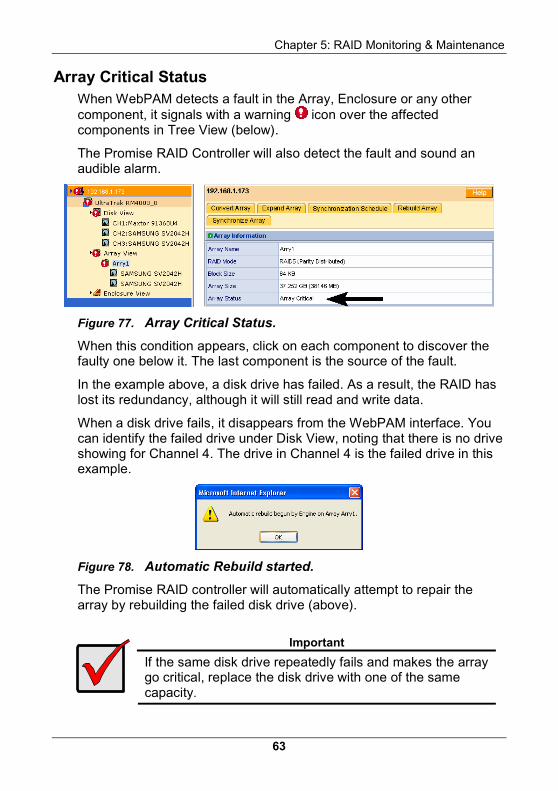
Array Critical Status When WebPAM detects a fault in the Array, Enclosure or any other component, it signals with a warning icon over the affected components in Tree View (below).
The Promise RAID Controller will also detect the fault and sound an audible alarm.
Figure 77. Array Critical Status.
When this condition appears, click on each component to discover the faulty one below it. The last component is the source of the fault.
In the example above, a disk drive has failed. As a result, the RAID has lost its redundancy, although it will still read and write data.
When a disk drive fails, it disappears from the WebPAM interface. You can identify the failed drive under Disk View, noting that there is no drive showing for Channel 4. The drive in Channel 4 is the failed drive in this example.
Figure 78. Automatic Rebuild started.
The Promise RAID controller will automatically attempt to repair the array by rebuilding the failed disk drive (above).
Important
If the same disk drive repeatedly fails and makes the array go critical, replace the disk drive with one of the same capacity.
WebPAM User Manual
64
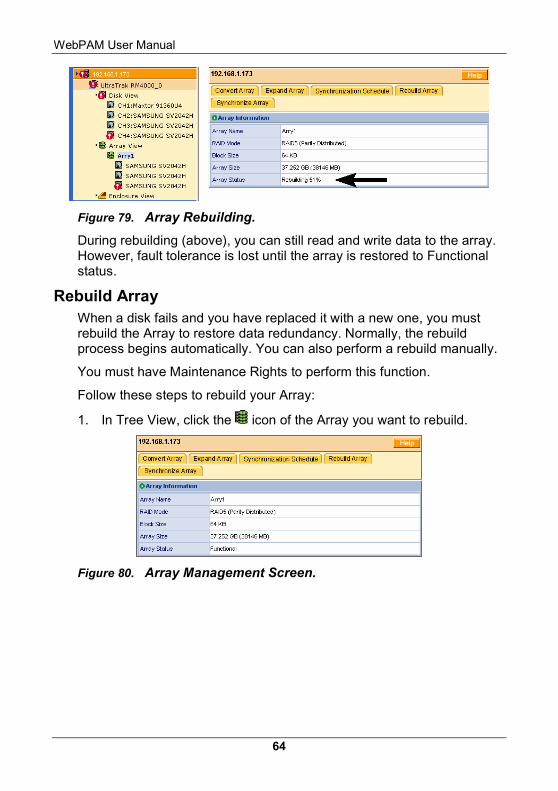
Figure 79. Array Rebuilding.
During rebuilding (above), you can still read and write data to the array. However, fault tolerance is lost until the array is restored to Functional status.
Rebuild Array When a disk fails and you have replaced it with a new one, you must rebuild the Array to restore data redundancy. Normally, the rebuild process begins automatically. You can also perform a rebuild manually.
You must have Maintenance Rights to perform this function.
Follow these steps to rebuild your Array:
1. In Tree View, click the icon of the Array you want to rebuild.
Figure 80. Array Management Screen.
Chapter 5: RAID Monitoring & Maintenance
65
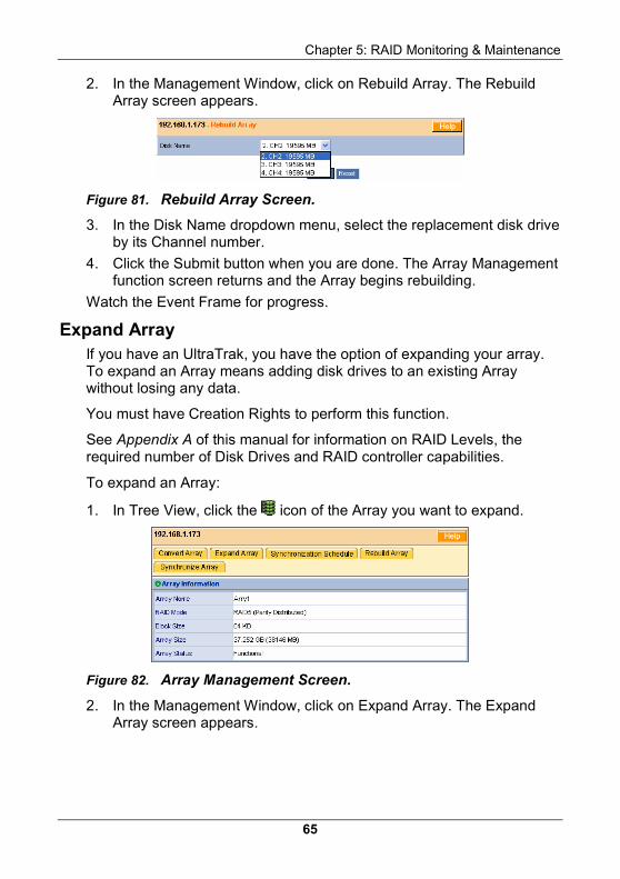
2. In the Management Window, click on Rebuild Array. The Rebuild Array screen appears.
Figure 81. Rebuild Array Screen.
3. In the Disk Name dropdown menu, select the replacement disk drive by its Channel number.
4. Click the Submit button when you are done. The Array Management function screen returns and the Array begins rebuilding.
Watch the Event Frame for progress.
Expand Array If you have an UltraTrak, you have the option of expanding your array. To expand an Array means adding disk drives to an existing Array without losing any data.
You must have Creation Rights to perform this function.
See Appendix A of this manual for information on RAID Levels, the required number of Disk Drives and RAID controller capabilities.
To expand an Array:
1. In Tree View, click the icon of the Array you want to expand.
Figure 82. Array Management Screen.
2. In the Management Window, click on Expand Array. The Expand Array screen appears.
WebPAM User Manual
66
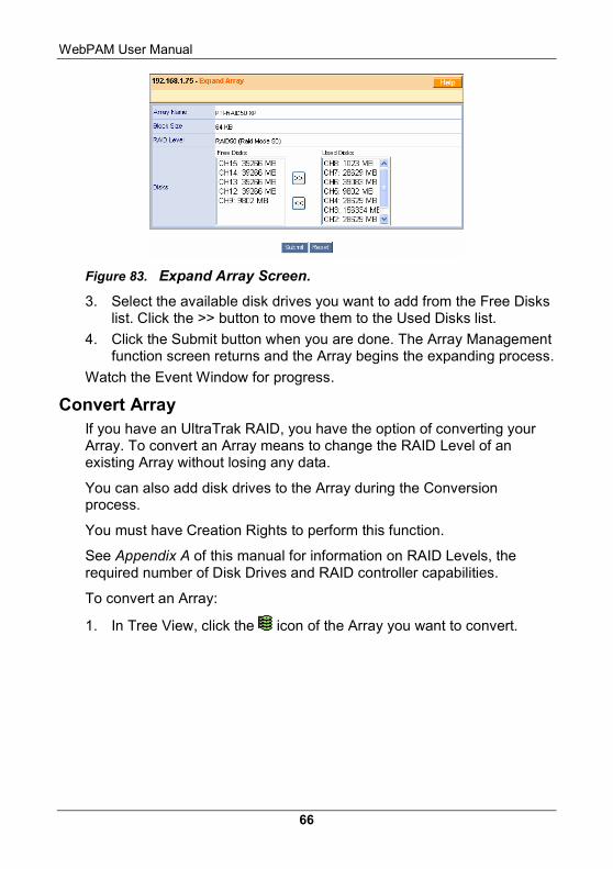
Figure 83. Expand Array Screen.
3. Select the available disk drives you want to add from the Free Disks list. Click the >> button to move them to the Used Disks list.
4. Click the Submit button when you are done. The Array Management function screen returns and the Array begins the expanding process.
Watch the Event Window for progress.
Convert Array If you have an UltraTrak RAID, you have the option of converting your Array. To convert an Array means to change the RAID Level of an existing Array without losing any data.
You can also add disk drives to the Array during the Conversion process.
You must have Creation Rights to perform this function.
See Appendix A of this manual for information on RAID Levels, the required number of Disk Drives and RAID controller capabilities.
To convert an Array:
1. In Tree View, click the icon of the Array you want to convert.
Chapter 5: RAID Monitoring & Maintenance
67
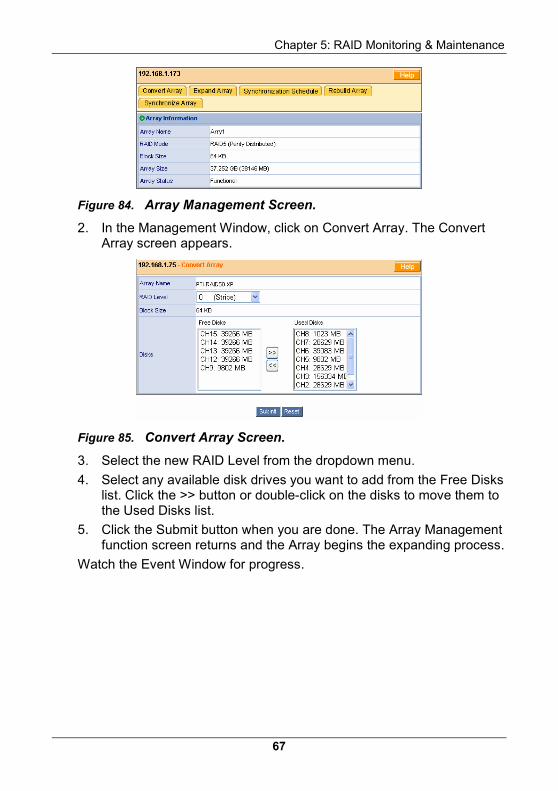
Figure 84. Array Management Screen.
2. In the Management Window, click on Convert Array. The Convert Array screen appears.
Figure 85. Convert Array Screen.
3. Select the new RAID Level from the dropdown menu.
4. Select any available disk drives you want to add from the Free Disks list. Click the >> button or double-click on the disks to move them to the Used Disks list.
5. Click the Submit button when you are done. The Array Management function screen returns and the Array begins the expanding process.
Watch the Event Window for progress.
WebPAM User Manual
68
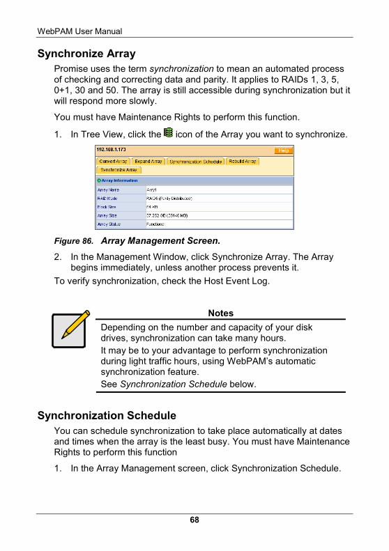
Synchronize Array Promise uses the term synchronization to mean an automated process of checking and correcting data and parity. It applies to RAIDs 1, 3, 5, 0+1, 30 and 50. The array is still accessible during synchronization but it will respond more slowly.
You must have Maintenance Rights to perform this function.
1. In Tree View, click the icon of the Array you want to synchronize.
Figure 86. Array Management Screen.
2. In the Management Window, click Synchronize Array. The Array begins immediately, unless another process prevents it.
To verify synchronization, check the Host Event Log.
Notes
Depending on the number and capacity of your disk drives, synchronization can take many hours. It may be to your advantage to perform synchronization during light traffic hours, using WebPAM’s automatic synchronization feature. See Synchronization Schedule below.
Synchronization Schedule You can schedule synchronization to take place automatically at dates and times when the array is the least busy. You must have Maintenance Rights to perform this function
1. In the Array Management screen, click Synchronization Schedule.
Chapter 5: RAID Monitoring & Maintenance
69
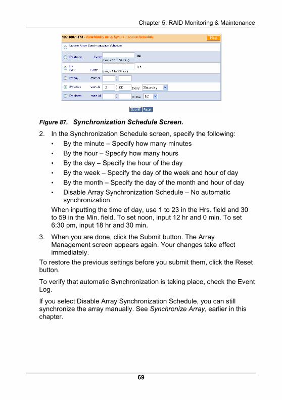
Figure 87. Synchronization Schedule Screen.
2. In the Synchronization Schedule screen, specify the following:
• By the minute – Specify how many minutes
• By the hour – Specify how many hours
• By the day – Specify the hour of the day
• By the week – Specify the day of the week and hour of day
• By the month – Specify the day of the month and hour of day
• Disable Array Synchronization Schedule – No automatic synchronization
When inputting the time of day, use 1 to 23 in the Hrs. field and 30 to 59 in the Min. field. To set noon, input 12 hr and 0 min. To set 6:30 pm, input 18 hr and 30 min.
3. When you are done, click the Submit button. The Array Management screen appears again. Your changes take effect immediately.
To restore the previous settings before you submit them, click the Reset button.
To verify that automatic Synchronization is taking place, check the Event Log.
If you select Disable Array Synchronization Schedule, you can still synchronize the array manually. See Synchronize Array, earlier in this chapter.
WebPAM User Manual
70
Array Functions This feature pertains to SuperTrak only.
1. In Tree View, click on the icon of the Array you want to rebuild.
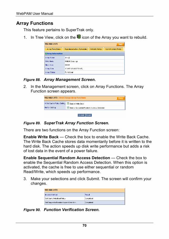
Figure 88. Array Management Screen.
2. In the Management screen, click on Array Functions. The Array Function screen appears.
Figure 89. SuperTrak Array Function Screen.
There are two functions on the Array Function screen:
Enable Write Back — Check the box to enable the Write Back Cache. The Write Back Cache stores data momentarily before it is written to the hard disk. The action speeds up disk write performance but adds a risk of lost data in the event of a power failure.
Enable Sequential Random Access Detection — Check the box to enable the Sequential Random Access Detection. When this option is activated, the cache is free to use either sequential or random Read/Write, which speeds up performance.
3. Make your selections and click Submit. The screen will confirm your changes.
Figure 90. Function Verification Screen.
Chapter 5: RAID Monitoring & Maintenance
71
If you changed the Enable Write Back function, you must restart the Host (RAID PC).
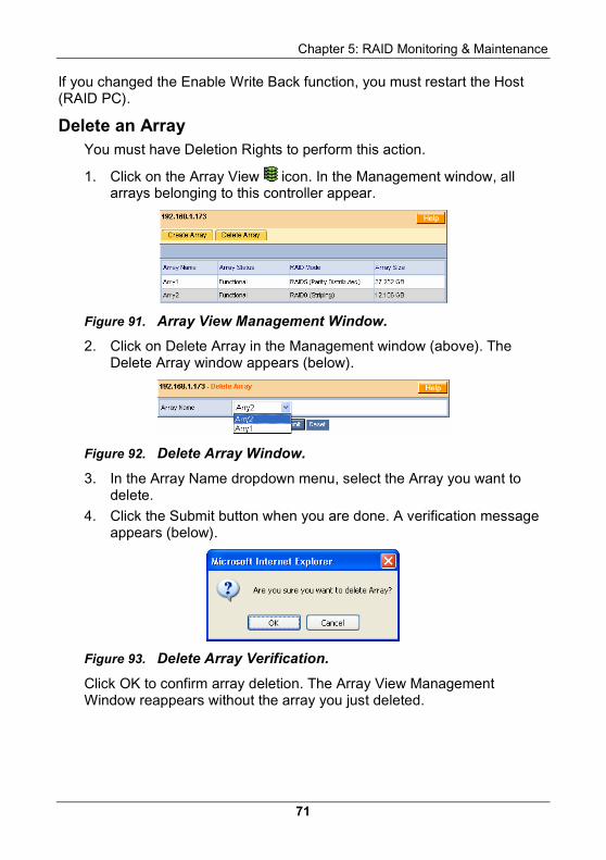
Delete an Array You must have Deletion Rights to perform this action.
1. Click on the Array View icon. In the Management window, all arrays belonging to this controller appear.
Figure 91. Array View Management Window.
2. Click on Delete Array in the Management window (above). The Delete Array window appears (below).
Figure 92. Delete Array Window.
3. In the Array Name dropdown menu, select the Array you want to delete.
4. Click the Submit button when you are done. A verification message appears (below).
Figure 93. Delete Array Verification.
Click OK to confirm array deletion. The Array View Management Window reappears without the array you just deleted.
WebPAM User Manual
72
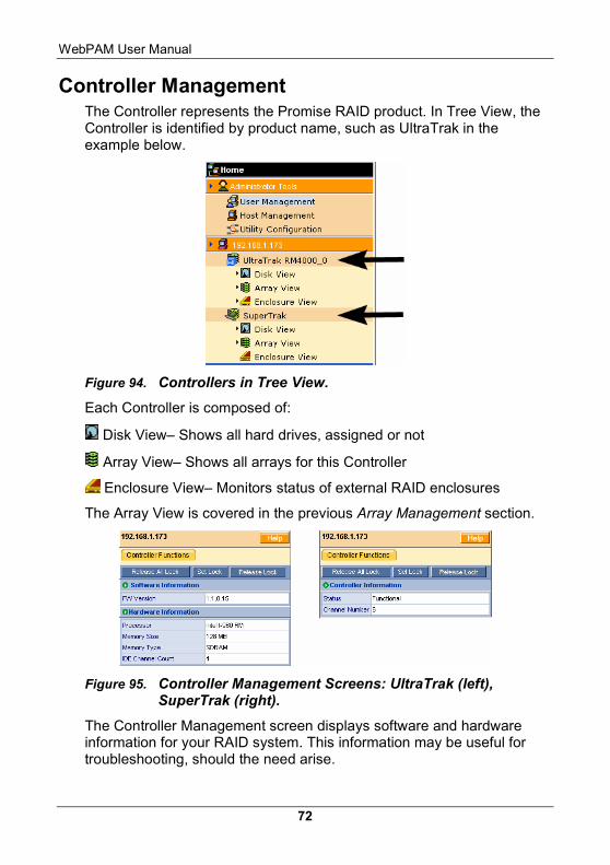
Controller Management The Controller represents the Promise RAID product. In Tree View, the Controller is identified by product name, such as UltraTrak in the example below.
Figure 94. Controllers in Tree View.
Each Controller is composed of:
Disk View– Shows all hard drives, assigned or not
Array View– Shows all arrays for this Controller
Enclosure View– Monitors status of external RAID enclosures
The Array View is covered in the previous Array Management section.
Figure 95. Controller Management Screens: UltraTrak (left), SuperTrak (right).
The Controller Management screen displays software and hardware information for your RAID system. This information may be useful for troubleshooting, should the need arise.
Chapter 5: RAID Monitoring & Maintenance
73
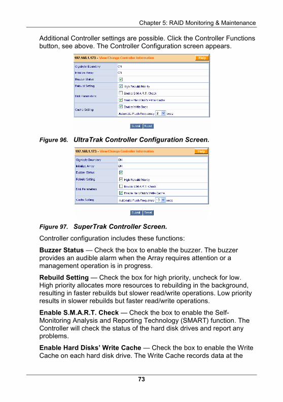
Additional Controller settings are possible. Click the Controller Functions button, see above. The Controller Configuration screen appears.
Figure 96. UltraTrak Controller Configuration Screen.
Figure 97. SuperTrak Controller Screen.
Controller configuration includes these functions:
Buzzer Status — Check the box to enable the buzzer. The buzzer provides an audible alarm when the Array requires attention or a management operation is in progress.
Rebuild Setting — Check the box for high priority, uncheck for low. High priority allocates more resources to rebuilding in the background, resulting in faster rebuilds but slower read/write operations. Low priority results in slower rebuilds but faster read/write operations.
Enable S.M.A.R.T. Check — Check the box to enable the Self-Monitoring Analysis and Reporting Technology (SMART) function. The Controller will check the status of the hard disk drives and report any problems.
Enable Hard Disks’ Write Cache — Check the box to enable the Write Cache on each hard disk drive. The Write Cache records data at the
WebPAM User Manual
74
same time as the hard disk. If the same data is needed right away, it is sent from the cache, speeding up read performance.
Enable Write Back — Check the box to enable the Write Back Cache. The Write Back Cache stores data momentarily before it is written to the hard disk. The action speeds up disk write performance but adds a risk of lost data in the event of a power failure. Applies to UltraTrak only.
Automatic Flush Frequency — Specify the frequency of Cache flushes from 0 to 59 seconds.
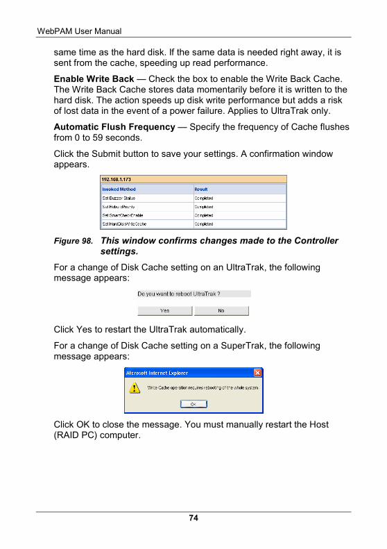
Click the Submit button to save your settings. A confirmation window appears.
Figure 98. This window confirms changes made to the Controller settings.
For a change of Disk Cache setting on an UltraTrak, the following message appears:
Click Yes to restart the UltraTrak automatically.
For a change of Disk Cache setting on a SuperTrak, the following message appears:
Click OK to close the message. You must manually restart the Host (RAID PC) computer.
Chapter 5: RAID Monitoring & Maintenance
75
Set / Release Lock Accessing an array to read or write data during maintenance or conversion causes the operation to take longer and yields decreased read/write performance until the operation is finished.
For array installations with multiple users on a network, you may experience unintended interference by other users. To prevent the interference, the Controller has a locking mechanism you can engage for operations such as rebuilding, conversion, expansion, manual synchronization and changing a disk drive.
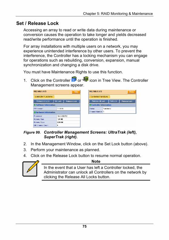
You must have Maintenance Rights to use this function.
1. Click on the Controller or icon in Tree View. The Controller Management screens appear.
Figure 99. Controller Management Screens: UltraTrak (left), SuperTrak (right).
2. In the Management Window, click on the Set Lock button (above).
3. Perform your maintenance as planned.
4. Click on the Release Lock button to resume normal operation.
Note
In the event that a User has left a Controller locked, the Administrator can unlock all Controllers on the network by clicking the Release All Locks button.
WebPAM User Manual
76
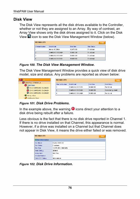
Disk View The Disk View represents all the disk drives available to the Controller, whether or not they are assigned to an Array. By way of contrast, an Array View shows only the disk drives assigned to it. Click on the Disk View icon to see the Disk View Management Window (below).
Figure 100. The Disk View Management Window.
The Disk View Management Window provides a quick view of disk drive model, size and status. Any problems are reported as shown below:
Figure 101. Disk Drive Problems.
In the example above, the warning icons direct your attention to a disk drive being rebuilt after a failure.
Less obvious is the fact that there is no disk drive reported in Channel 1. If there is no drive installed on that Channel, this appearance is normal. However, if a drive was installed on a Channel but that Channel does not appear in Disk View, it means the drive either failed or was removed.
Figure 102. Disk Drive Information.
Chapter 5: RAID Monitoring & Maintenance
77
Click on a Disk icon to see information about an individual Disk Drive. The information includes:
• Disk Model — Manufacturer and model of the Disk Drive
• Disk Status — Functional or Rebuilding
• Disk size — Disk capacity in GB and MB
• Mode setting — UDMA level on which the drive is operating
• Assignment — Assigned to an array or unassigned
• Channel number — Controller channel on which the drive is operating
• SMART status — Indicates whether the drive’s SMART feature is available and/or working
This information can be helpful in troubleshooting and ensuring your RAID is functioning at its optimum level.
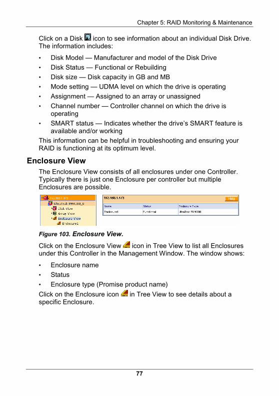
Enclosure View The Enclosure View consists of all enclosures under one Controller. Typically there is just one Enclosure per controller but multiple Enclosures are possible.
Figure 103. Enclosure View.
Click on the Enclosure View icon in Tree View to list all Enclosures under this Controller in the Management Window. The window shows:
• Enclosure name
• Status
• Enclosure type (Promise product name)
Click on the Enclosure icon in Tree View to see details about a specific Enclosure.
WebPAM User Manual
78
Figure 104. Enclosure Window.
The Enclosure Window displays:
Enclosure Type – Lists the model of enclosure, in this case an UltraTrak RM4000.
Fan Speeds – Each drive in the enclosure has a cooling fan. Above 2,000 rpm is normal speed. When a fan turns slowly or stops, it requires attention.
OK
Problem
Temperature – 30°C (86°F) is normal. Each sensor displays a reading. If the temperature climbs above 52°C (124°F), it may be due to a broken fan or blocked cooling passages and requires attention.
OK
Problem
OK
Power Status – Shows the voltages of the 12- and 5-volt circuits inside the enclosure. If these voltages are above or below specification, there may be a problem with the power supply.
Problem
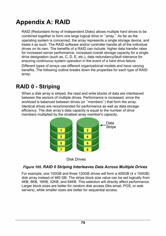
79
Appendix A: RAID RAID (Redundant Array of Independent Disks) allows multiple hard drives to be combined together to form one large logical drive or “array.” As far as the operating system is concerned, the array represents a single storage device, and treats it as such. The RAID software and/or controller handle all of the individual drives on its own. The benefits of a RAID can include: higher data transfer rates for increased server performance, increased overall storage capacity for a single drive designation (such as, C, D, E, etc.), data redundancy/fault tolerance for ensuring continuous system operation in the event of a hard drive failure. Different types of arrays use different organizational models and have varying benefits. The following outline breaks down the properties for each type of RAID array:
RAID 0 - Striping When a disk array is striped, the read and write blocks of data are interleaved between the sectors of multiple drives. Performance is increased, since the workload is balanced between drives (or “members”) that form the array. Identical drives are recommended for performance as well as data storage efficiency. The disk array’s data capacity is equal to the number of drive members multiplied by the smallest array member's capacity.
1
3
5
7
2
4
6
8
Disk Drives
DataStripe
Figure 105. RAID 0 Striping Interleaves Data Across Multiple Drives For example, one 100GB and three 120GB drives will form a 400GB (4 x 100GB) disk array instead of 460 GB. The stripe block size value can be set logically from 4KB, 8KB, 16KB, 32KB, and 64KB. This selection will directly affect performance. Larger block sizes are better for random disk access (like email, POS, or web servers), while smaller sizes are better for sequential access.
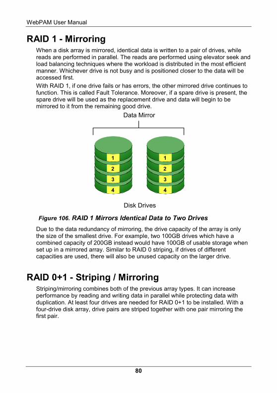
WebPAM User Manual
80
RAID 1 - Mirroring When a disk array is mirrored, identical data is written to a pair of drives, while reads are performed in parallel. The reads are performed using elevator seek and load balancing techniques where the workload is distributed in the most efficient manner. Whichever drive is not busy and is positioned closer to the data will be accessed first. With RAID 1, if one drive fails or has errors, the other mirrored drive continues to function. This is called Fault Tolerance. Moreover, if a spare drive is present, the spare drive will be used as the replacement drive and data will begin to be mirrored to it from the remaining good drive.
1
2
3
4
1
2
3
4
Disk Drives
Data Mirror
Figure 106. RAID 1 Mirrors Identical Data to Two Drives Due to the data redundancy of mirroring, the drive capacity of the array is only the size of the smallest drive. For example, two 100GB drives which have a combined capacity of 200GB instead would have 100GB of usable storage when set up in a mirrored array. Similar to RAID 0 striping, if drives of different capacities are used, there will also be unused capacity on the larger drive.
RAID 0+1 - Striping / Mirroring Striping/mirroring combines both of the previous array types. It can increase performance by reading and writing data in parallel while protecting data with duplication. At least four drives are needed for RAID 0+1 to be installed. With a four-drive disk array, drive pairs are striped together with one pair mirroring the first pair.
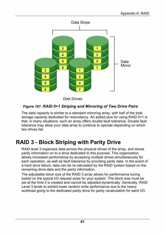
Appendix A: RAID
81
2
4
6
8
1
3
5
72
4
6
8
1
3
5
7
Disk Drives
DataMirror
Data Stripe
Figure 107. RAID 0+1 Striping and Mirroring of Two Drive Pairs The data capacity is similar to a standard mirroring array, with half of the total storage capacity dedicated for redundancy. An added plus for using RAID 0+1 is that, in many situations, such an array offers double fault tolerance. Double fault tolerance may allow your data array to continue to operate depending on which two drives fail.
RAID 3 - Block Striping with Parity Drive RAID level 3 organizes data across the physical drives of the array, and stores parity information on to a drive dedicated to this purpose. This organization allows increased performance by accessing multiple drives simultaneously for each operation, as well as fault tolerance by providing parity data. In the event of a hard drive failure, data can be re-calculated by the RAID system based on the remaining drive data and the parity information. The adjustable block size of the RAID 3 array allows for performance tuning based on the typical I/O request sizes for your system. The block size must be set at the time it is created and cannot be adjusted dynamically. Generally, RAID Level 3 tends to exhibit lower random write performance due to the heavy workload going to the dedicated parity drive for parity recalculation for each I/O.
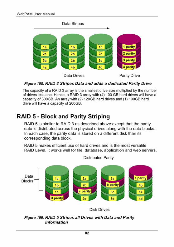
WebPAM User Manual
82
Data Drives Parity Drive
1 parity
2 parity
3 parity
4 parity
1c
2c
3c
4c
1b
2b
3b
4b
1a
2a
3a
4a
Data Stripes
Figure 108. RAID 3 Stripes Data and adds a dedicated Parity Drive The capacity of a RAID 3 array is the smallest drive size multiplied by the number of drives less one. Hence, a RAID 3 array with (4) 100 GB hard drives will have a capacity of 300GB. An array with (2) 120GB hard drives and (1) 100GB hard drive will have a capacity of 200GB.
RAID 5 - Block and Parity Striping RAID 5 is similar to RAID 3 as described above except that the parity data is distributed across the physical drives along with the data blocks. In each case, the parity data is stored on a different disk than its corresponding data block.
RAID 5 makes efficient use of hard drives and is the most versatile RAID Level. It works well for file, database, application and web servers.
4b
4c
4d
a parity3a
3c
3d
b parity
2a
2b
2d
c parity
1a
1b
1c
d parity
Disk Drives
Distributed Parity
DataBlocks
Figure 109. RAID 5 Stripes all Drives with Data and Parity Information
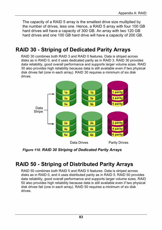
Appendix A: RAID
83
The capacity of a RAID 5 array is the smallest drive size multiplied by the number of drives, less one. Hence, a RAID 5 array with four 100 GB hard drives will have a capacity of 300 GB. An array with two 120 GB hard drives and one 100 GB hard drive will have a capacity of 200 GB.
RAID 30 - Striping of Dedicated Parity Arrays RAID 30 combines both RAID 3 and RAID 0 features. Data is striped across disks as in RAID 0, and it uses dedicated parity as in RAID 3. RAID 30 provides data reliability, good overall performance and supports larger volume sizes. RAID 30 also provides high reliability because data is still available even if two physical disk drives fail (one in each array). RAID 30 requires a minimum of six disk drives.
Data Drives Parity Drives
1 parity
3 parity
5 parity
1b
3b
5b
1a
3a
5a
2 parity
4 parity
6 parity
2b
4b
6b
2a
4a
6a
DataStripe
Figure 110. RAID 30 Striping of Dedicated Parity Arrays
RAID 50 - Striping of Distributed Parity Arrays RAID 50 combines both RAID 5 and RAID 0 features. Data is striped across disks as in RAID 0, and it uses distributed parity as in RAID 5. RAID 50 provides data reliability, good overall performance and supports larger volume sizes. RAID 50 also provides high reliability because data is still available even if two physical disk drives fail (one in each array). RAID 50 requires a minimum of six disk drives.
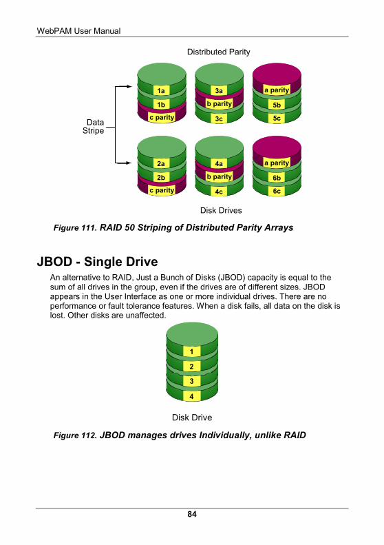
WebPAM User Manual
84
5b
5c
a parity3a
3c
b parity
1a
1b
c parity
6b
6c
a parity4a
4c
b parity
2a
2b
c parity
Disk Drives
Distributed Parity
DataStripe
Figure 111. RAID 50 Striping of Distributed Parity Arrays
JBOD - Single Drive An alternative to RAID, Just a Bunch of Disks (JBOD) capacity is equal to the sum of all drives in the group, even if the drives are of different sizes. JBOD appears in the User Interface as one or more individual drives. There are no performance or fault tolerance features. When a disk fails, all data on the disk is lost. Other disks are unaffected.
Disk Drive
1
2
3
4
Figure 112. JBOD manages drives Individually, unlike RAID
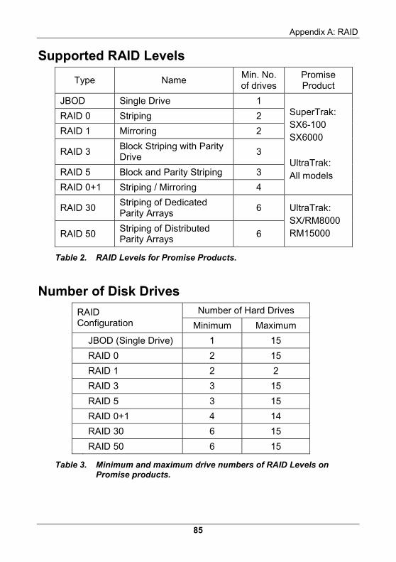
Appendix A: RAID
85
Supported RAID Levels
Type Name Min. No. of drives
Promise Product
JBOD Single Drive 1
RAID 0 Striping 2
RAID 1 Mirroring 2
RAID 3 Block Striping with Parity Drive
3
RAID 5 Block and Parity Striping 3
RAID 0+1 Striping / Mirroring 4
SuperTrak: SX6-100 SX6000 UltraTrak: All models
RAID 30 Striping of Dedicated Parity Arrays
6
RAID 50 Striping of Distributed Parity Arrays
6
UltraTrak: SX/RM8000 RM15000
Table 2. RAID Levels for Promise Products.
Number of Disk Drives Number of Hard Drives RAID
Configuration Minimum Maximum
JBOD (Single Drive) 1 15
RAID 0 2 15
RAID 1 2 2
RAID 3 3 15
RAID 5 3 15
RAID 0+1 4 14
RAID 30 6 15
RAID 50 6 15
Table 3. Minimum and maximum drive numbers of RAID Levels on Promise products.
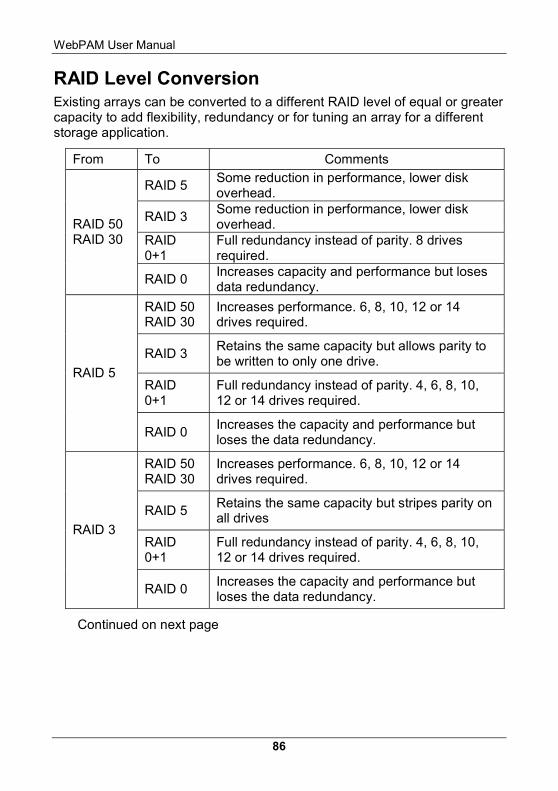
WebPAM User Manual
86
RAID Level Conversion Existing arrays can be converted to a different RAID level of equal or greater capacity to add flexibility, redundancy or for tuning an array for a different storage application.
From To Comments
RAID 5 Some reduction in performance, lower disk overhead.
RAID 3 Some reduction in performance, lower disk overhead.
RAID 0+1
Full redundancy instead of parity. 8 drives required.
RAID 50 RAID 30
RAID 0 Increases capacity and performance but loses data redundancy.
RAID 50 RAID 30
Increases performance. 6, 8, 10, 12 or 14 drives required.
RAID 3 Retains the same capacity but allows parity to be written to only one drive.
RAID 0+1
Full redundancy instead of parity. 4, 6, 8, 10, 12 or 14 drives required.
RAID 5
RAID 0 Increases the capacity and performance but loses the data redundancy.
RAID 50 RAID 30
Increases performance. 6, 8, 10, 12 or 14 drives required.
RAID 5 Retains the same capacity but stripes parity on all drives
RAID 0+1
Full redundancy instead of parity. 4, 6, 8, 10, 12 or 14 drives required.
RAID 3
RAID 0 Increases the capacity and performance but loses the data redundancy.
Continued on next page
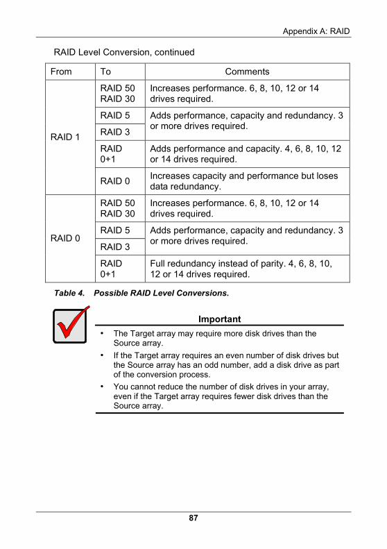
Appendix A: RAID
87
RAID Level Conversion, continued
From To Comments
RAID 50 RAID 30
Increases performance. 6, 8, 10, 12 or 14 drives required.
RAID 5
RAID 3
Adds performance, capacity and redundancy. 3 or more drives required.
RAID 0+1
Adds performance and capacity. 4, 6, 8, 10, 12 or 14 drives required.
RAID 1
RAID 0 Increases capacity and performance but loses data redundancy.
RAID 50 RAID 30
Increases performance. 6, 8, 10, 12 or 14 drives required.
RAID 5
RAID 3
Adds performance, capacity and redundancy. 3 or more drives required. RAID 0
RAID 0+1
Full redundancy instead of parity. 4, 6, 8, 10, 12 or 14 drives required.
Table 4. Possible RAID Level Conversions.
Important
• The Target array may require more disk drives than the
Source array.
• If the Target array requires an even number of disk drives but the Source array has an odd number, add a disk drive as part of the conversion process.
• You cannot reduce the number of disk drives in your array, even if the Target array requires fewer disk drives than the Source array.

WebPAM User Manual
88
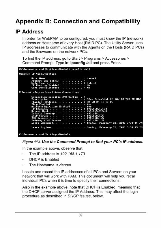
89
Appendix B: Connection and Compatibility IP Address
In order for WebPAM to be configured, you must know the IP (network) address or Hostname of every Host (RAID PC). The Utility Server uses IP addresses to communicate with the Agents on the Hosts (RAID PCs) and the Browsers on the network PCs.
To find the IP address, go to Start > Programs > Accessories > Command Prompt. Type in: ipconfig /all and press Enter.
Figure 113. Use the Command Prompt to find your PC’s IP address.
In the example above, observe that:
• The IP address is 192.168.1.173
• DHCP is Enabled
• The Hostname is dannel
Locate and record the IP addresses of all PCs and Servers on your network that will work with PAM. This document will help you recall individual PCs when it is time to specify their connections.
Also in the example above, note that DHCP is Enabled, meaning that the DHCP server assigned the IP Address. This may affect the login procedure as described in DHCP Issues, below.
WebPAM User Manual
90
DHCP Issues DHCP stands for Dynamic Host Configuration Protocol and refers to software that allows a file server to assign IP addresses to computers on the network. DHCP is very helpful in reducing the number of IP address a company or organization requires.
The DHCP server assigns an IP address to a computer as it logs onto the network. The IP address will remain the same until the computer logs off or disconnects for any reason, such as a power failure. When the computer logs on again, it will receive a different IP address. However, the computer’s Hostname remains the same.
Because IP addresses are subject to change when a DHCP server is involved, use either of these alternatives:
• Maintain the Host’s (RAID PC’s) network connection at all times.
• Use the Hostname when creating a Machine in WebPAM.
If you used the IP Address for a Host (RAID PC) and a disconnection happens for any reason, you must find the new IP address and enter create a new Host (RAID PC) in your WebPAM browser. Instructions for doing this appear under Host Management in Chapter 5.
Operating System Support WebPAM is a utility designed to run on top of previously installed Promise controller card or RAID products. Generally, if your Windows PC runs the Promise card or RAID properly, it will run WebPAM also. This release of WebPAM does not run on Linux.
Promise Technology recommends Windows NT 4.0, 2000 and XP Professional to take full advantage of all the features of WebPAM.
Network Requirements Since WebPAM is designed for network operation, be sure all the hosts and servers are connected and running. Each of the PCs, RAIDs and Servers must have a working network connection before you can configure WebPAM.
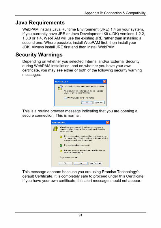
Appendix B: Connection & Compatibility
91
Java Requirements WebPAM installs Java Runtime Environment (JRE) 1.4 on your system. If you currently have JRE or Java Development Kit (JDK) versions 1.2.2, 1.3.0 or 1.4, WebPAM will use the existing JRE rather than installing a second one. Where possible, install WebPAM first, then install your JDK. Always install JRE first and then install WebPAM.
Security Warnings Depending on whether you selected Internal and/or External Security during WebPAM installation, and on whether you have your own certificate, you may see either or both of the following security warning messages:
This is a routine browser message indicating that you are opening a secure connection. This is normal.
This message appears because you are using Promise Technology's default Certificate. It is completely safe to proceed under this Certificate. If you have your own certificate, this alert message should not appear.
WebPAM User Manual
92
Selected Definitions While Promise WebPAM uses proven technologies, a few key terms may be new to some users. Following are brief definitions of key terms used in this manual.
CIMOM – CIMOM (Pronounced “SEE mom”) stands for Common Information Model Object Management. Common Information Model (CIM) is a protocol used to manage Internet-based storage. Object Manager (OM) is server software that implements the CIM protocol.
Host – In network language, an end-user’s computer, when connected to a network, is referred to as a Host. A Hostname consists of a PC’s individual name and the domain to which it belongs.
In WebPAM, a Host is also called a “RAID PC”, because the Host is the PC that manages the RAID.
WBEM – WBEM stands for Web-Based Enterprise Management. It is a collection of Internet technologies used to manage systems and networks throughout the enterprise. WBEM uses the CIM protocol as the database for information about computer systems and network devices.
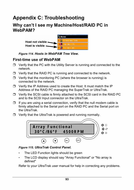
93
Appendix C: Troubleshooting Why can’t I see my Machine/Host/RAID PC in WebPAM?
Figure 114. Hosts in WebPAM Tree View.
First-time use of WebPAM Verify that the PC with the Utility Server is running and connected to the
network.
Verify that the RAID PC is running and connected to the network.
Verify that the monitoring PC (where the browser is running) is connected to the network.
Verify the IP Address used to create the Host. It must match the IP Address of the RAID PC managing the SuperTrak or UltraTrak.
Verify the SCSI cable is firmly attached to the SCSI card in the RAID PC and to the SCSI Input connector on the UltraTrak.
If you are using a serial connection, verify that the null modem cable is firmly attached to the Serial port on the RAID PC and the Serial port on the UltraTrak.
Verify that the UltraTrak is powered and running normally.
SEL EXIT
A r r a y F u n c t i o n a l 3 0 ° C / 8 6 ° F 4 5 0 0 R P M
Figure 115. UltraTrak Control Panel.
• The LED Function lights should be green
• The LCD display should say "Array Functional" or "No array is defined"
Refer to your UltraTrak user manual for help in correcting any problems.
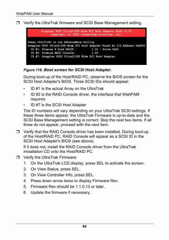
WebPAM User Manual
94
Verify the UltraTrak firmware and SCSI Base Management setting.
Figure 116. Boot screen for SCSI Host Adapter.
During boot-up of the Host/RAID PC, observe the BIOS screen for the SCSI Host Adapter's BIOS. Three SCSI IDs should appear:
• ID #1 is the actual Array on the UltraTrak
• ID #2 is the RAID Console driver, the interface that WebPAM requires
• ID #7 is the SCSI Host Adapter
The ID numbers will vary depending on your UltraTrak SCSI settings. If these three items appear, the UltraTrak Firmware is up-to-date and the SCSI Base Management setting is correct. Skip the next two items. If all three do not appear, proceed with the next item.
Verify that the RAID Console driver has been installed. During boot-up of the Host/RAID PC, RAID Console will appear as a SCSI ID in the SCSI Host Adapter's BIOS (see above).
If it does not, install the RAID Console driver from the UltraTrak Installation CD onto the Host/RAID PC.
Verify the UltraTrak Firmware:
1. On the UltraTrak LCD display, press SEL to activate the screen.
2. On View Status, press SEL.
3. On View Controller Info, press SEL.
4. Press down arrow twice to display Firmware Rev.
5. Firmware Rev should be 1.1.0.13 or later.
6. Update the firmware if necessary.
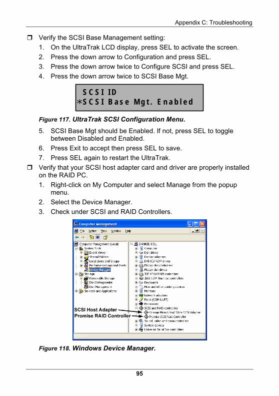
Appendix C: Troubleshooting
95
Verify the SCSI Base Management setting:
1. On the UltraTrak LCD display, press SEL to activate the screen.
2. Press the down arrow to Configuration and press SEL.
3. Press the down arrow twice to Configure SCSI and press SEL.
4. Press the down arrow twice to SCSI Base Mgt.
S C S I I DS C S I B a s e M g t . E n a b l e d
Figure 117. UltraTrak SCSI Configuration Menu.
5. SCSI Base Mgt should be Enabled. If not, press SEL to toggle between Disabled and Enabled.
6. Press Exit to accept then press SEL to save.
7. Press SEL again to restart the UltraTrak.
Verify that your SCSI host adapter card and driver are properly installed on the RAID PC.
1. Right-click on My Computer and select Manage from the popup menu.
2. Select the Device Manager.
3. Check under SCSI and RAID Controllers.
Figure 118. Windows Device Manager.
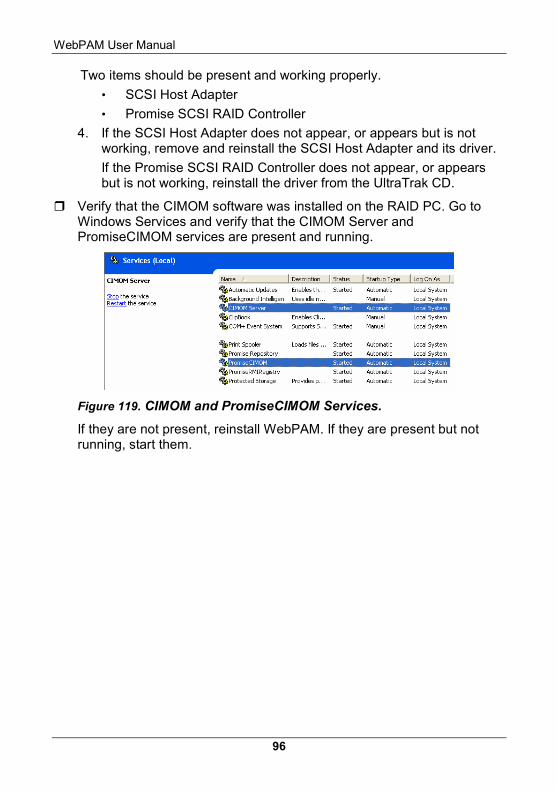
WebPAM User Manual
96
Two items should be present and working properly.
• SCSI Host Adapter
• Promise SCSI RAID Controller
4. If the SCSI Host Adapter does not appear, or appears but is not working, remove and reinstall the SCSI Host Adapter and its driver.
If the Promise SCSI RAID Controller does not appear, or appears but is not working, reinstall the driver from the UltraTrak CD.
Verify that the CIMOM software was installed on the RAID PC. Go to Windows Services and verify that the CIMOM Server and PromiseCIMOM services are present and running.
Figure 119. CIMOM and PromiseCIMOM Services.
If they are not present, reinstall WebPAM. If they are present but not running, start them.

Appendix C: Troubleshooting
97
Verify that the Utility Server was installed on a network PC or Server. On the same PC or Server, go to Windows Services and verify that the Tomcat service is present and running.
Figure 120. Tomcat Service.
If the Tomcat service is not present, reinstall the WebPAM Utility Server.
If the Tomcat service is present but not running, start it.
If the Tomcat service is present and running but connection still does not work, there may be a port conflict.
1. Go to the WebPAM/Tomcat/conf folder and open the server.xml file.
2. Change the default port 8080 (no security) or 8443 (security), whichever you are using, to a different number.
3. Use the new number when you type the Host IP address into your browser.
Verify that there is only one instance of the Utility Server installed on the network.
If there is more than one Utility Server installed on the network. Uninstall all instances of the Utility Server except for one.
WebPAM User Manual
98
WebPAM worked before but now it doesn’t Verify that the PC with the Utility Server is running and connected to the
network.
Verify that the RAID PC is running and connected to the network.
Verify that the monitoring PC (where the browser is running) is connected to the network.
If the UltraTrak reboots, it will temporally disconnect. It will automatically reconnect a few moments after booting is completed.
Verify the IP Address used to create the Host. It must match the IP Address of the RAID PC managing the SuperTrak or UltraTrak. The IP Address may have changed if the RAID PC was shut down.
Verify the SCSI cable is firmly attached to the SCSI card in the RAID PC and to the SCSI Input connector on the UltraTrak.
If you are using a serial connection, verify that the null modem cable is firmly attached to the Serial port on the RAID PC and the Serial port on the UltraTrak.
Verify that the UltraTrak is powered and running normally.
• The LED Function lights should be green
• The LCD display should say "Array Functional" or "No array is defined"
Refer to your UltraTrak user manual for help in correcting any problems.
On the RAID PC, go to Windows Services and verify that the CIMOM Server and PromiseCIMOM services are present and running.
If they are not running, start them.
On the network PC or Server where the Utility Server was installed, go to Windows Services and verify that the Tomcat service is present and running.
If it is not running, start it.
Determine whether any WebPAM installations have taken place elsewhere on the network and verify that there is only one Utility Server on the network.