Embed Size (px)
Citation preview

Webb Institute, Glen Cove, New York
The principal objective of this research was to determine the merit of transom lift devices on high-performance sailing craft. Transom lift devices modify running trim and also produce several other less-obvious hydrodynamic effects, all of which alter total resistance, thereby affecting the maximum speed achievable under sail. Transom lift devices, in the form of trim tabs, planing wedges, and interceptors, have been used with considerable and quantifiable success for many years on powered craft in both the planing and displacement regimes. This undergraduate thesis extends that research to a round-bilged sailing yacht, the Open 60 Imagine an older Open 60 hull-form by Kaufmann Designs. The effect of transom lift devices was tested on the one-tenth scale model of Imagine in the Robinson Model Basin at Webb Institute. Heel angles of 0, 5, and 10 degrees were investigated at a range of speeds from 1.087 to 13.89 feet per second, model-scale, corresponding to full-scale speeds from 2 to 26 knots. A simplified testing matrix was chosen that did not investigate model yaw, side force, or leeway.
Resistance, trim, and sinkage were measured. The study found that transom lift devices, particularly interceptors, greatly affect the trim of the yacht. The devices decrease resistance in the hump region, although on Imagine these decreases were small in magnitude. Importantly, it was shown that the benefits of transom lift devices seem likely to continue even when the yacht is heeled. Outside the hump-region, at both high and low speeds, resistance increased considerably in all configurations. This is thought to be due to increased bow-wetted surface and loss of lift due to excessively decreased trim at the higher speeds. However, it is believed that this study shows that there is considerable merit to the further investigation of transom lift devices on sailing yachts such as Open 60s,particularly more recent hull forms.
This paper summarizes work completed for an undergraduate thesis at Webb Institute. Elements of the paper have been designed to meet the original thesis project requirements. Full copies of the original thesis can be obtained from the author or accessed through Webb Institute.
ANNAPOLIS, MARYLAND, MARCH 2011
139
APM Added Pitching Moment b Beam Cb Block Coefficient Cf Frictional Drag Coefficient Cm Midship Coefficient Cp Prismatic Coefficient Cv Speed Coefficient Cx General Resistance Coefficient D Total Horizontal Drag Force (Interceptor) Disp Displacement Df Drag due to viscous effects Fn Froude Number g Acceleration Due to Gravity ip Interceptor Depth L Vessel Length LCB Longitudinal Center of Buoyancy LCG Longitudinal Center of Gravity LOA Length Over All LWL Length of Water Line Lw Wetted length Rn Reynolds Number Rx General Resistance Component WSA Surface Area V Vessel velocity V1 Velocity over planing surface VCB Vertical Center of Buoyancy
Deadrise Angle Total Displacement (Weight) Density of water Trim Angle Kinematic Viscosity
In the realm of powered vessels, it has long been known that trim altering devices such as trim tabs and transom wedges can reduce resistance or alter the sea keeping performance of a vessel. Webb Institute has produced several studies of the effects of trim tabs and wedges on various vessel types from prismatic planing hulls to displacement catamaran hulls. What is less well known ishow these devices might affect the performance of a vessel under sail. This thesis aims to determine the effects of two trim altering devices on the resistance of a high performance sailing yacht.
The model tested is an Open 60 class monohull. These yachts are designed principally for off-shore racing such as trans-ocean and around-the-world courses. The Open 60 is a development classdesigners significant freedom, so long as the end product meets certain basic parameters. This freedom allows designers to look at innovative solutions to make the yachts
travel faster. Trim altering devices are one such solution that has been employed on several Open 60s.
Two different types of trim altering devices have been used to date on Open 60s. Both provide variable control of trim and, therefore, affect the resistance of the vessel. The devices may also offer benefits to resistance beyond those realized through trim control. There have been many studies of transom submergence in vessel design (Cain, 2007), (Bryn, 2006), and essentially this is what trim tabs and interceptors affect. At low speeds, non-submerged transoms are helpful in the reduction of eddy resistance and are preferable. At higher speeds, where separation occurs, submerged transoms may increase the effective waterline length of the vessel, thereby decreasing resistance. However, there is a trade-off with form drag as the submerged transom induces a reduced pressure aft, which adds to resistance. The key is finding the balance point that minimizes total resistance. Varying transom submergence with trim-altering devices allows a vessel to have multiple
each. The first trim-altering device examined is the traditional
power-craft style trim tab. A trim tab is essentially a large, hinged surface that, when retracted, is a fair continuation of the hull surface. When lowered, the tab deflects flow, producing a bow-down moment on the yacht. Tabs have recently been employed on the Farr-designed Open 60 yachts Paprec-Virbac 2 and Gitana 80.
The second device investigated is an interceptor. Interceptors are a far newer concept than tabs. An interceptor consists of a flat, vertical plate affixed to or just forward of the transom. The plate spans the beam of the yacht, but is at most only several centimeters deep. The pressure distribution formed at the interceptor produces a bow-down moment, as with a trim tab. Interceptors are known to be in use on the Owen Clarke designed Open 60s Aviva and Ecover and on the Rogers-designed Artemis II.
The objective of this thesis is to determine the relative
performance. Of special interest is the performance of the trim tab and interceptor while a yacht is heeled. Additionally, it is hoped that this thesis can serve to expandthe knowledge base with regard to the effect of tabs and particularly interceptors on all vessels.
The testing platform being utilized in this thesis is the six-foot Open 60 yacht model Imagine. The full-sized yacht, Imagine, was the focus of a paper for the 12th CSYS, entitled Imagine an Open Class 60 BOC Racer Design and Program Management Lessons Learned. The model, built to Imagine's lines, was constructed by the thesis team of Falls, Hutchings, and Ward for their 1995 thesis The Application of Model Test Analysis and Ocean Race Simulation to the Performance Prediction and Design Optimization of Open Unlimited 60 Class Yachts. Testing was performed in the Robinson Model Basin using the
140

Open 60 model which has been modified with a trim-tab and interceptor for various tests. The model was run at varied heel angles, speeds, and tab or interceptor depths. Limitations of the dynamometer preclude the measurement of dynamic heeling forces and leeway also was not included in testing. This does not compromise the utility of the results because these measurements are important for upwind sailing, whereas the transom lift devices we are examining would be principally used down wind. When sailing down wind, the foils are not required to generate significant lift, and the hull does not experience considerable leeway, so this can be ignored.
Two regimes must be taken into consideration in this research. Because of the extreme variability of the driving force applied to the Open 60 via its sail plan as a result of varying wind strengths, the vessel will operate over a large range of speeds. Consequently, the yacht will spend time in both displacement and planing modes. The displacement and planing modes must each be considered when evaluating the performance effects of tabs, interceptors, or other transom lift devices. There has been considerable research regarding the use of transom lift devices in both planing and displacement modes, particularly for naval vessels from patrol boats to destroyers. This research has shown that transom lift devices can result in decreased resistance in both modes. However, the decrease in resistance is achieved differently in displacement and planing vessels. Planing craft have historically been defined as those
the speed at which a vessel creates a wave equal to its own length, which effectively is the limiting speed for a displacement craft. This limit occurs at a Froude number of 0.399. The Froude number is a non-dimensional measure of vessel speed and is defined as
where V is the vessel speed, g is gravitational acceleration, and L is the vessel length. Any units can be used, provided they are consistent between terms. From a Froude number of 0.399 to approximately 0.892, there is a transition from displacement to full planing that is often called the semi-planing region. At Froude numbers below about 0.266, frictional resistance dominates. Above Fn = 0.266 and for displacement craft, wave-making resistance increases dramatically as Froude number approaches 0.399,consistent with the concept of hull speed. An illustration of a displacement/semi-displacement vessel traveling through a speed range appears in Figure 1. It can be seen that the vessel is literally sinking into the water; as the vessel
attempts to go faster and faster, it settles into the trough of the wave created by its bow, unable to overcome the face of the bow wave. Although the yacht is technically beyond the displacement regime, its higher power allows for higher speeds, thereby blurring the line between displacement and planing modes, thus necessitating the semi-displacement designation. This sinkage is characteristic of all displacement craft as speed increases. For semi-planing and planing craft that can surpass hull speed by overcoming the bow wave, the wave making resistance begins to level off after Fn = 0.399 and the frictional resistance again becomes important. The wave-making resistance remains roughly constant for Froude Numbers greater than 0.528 and the frictional resistance again dominates, with a magnitude of roughly twice the wave-making component (Savitsky, 1964). The components of resistance will be discussed further in the section on procedure.
The 80-foot Steam Yacht Ellide Accelerating from 16.6 to 34.8 knots, Fn from 0.33 to 0.69
Source: Professional Boatbuilder, June/July 2008
The planing phenomenon is made possible by the lift created by the vessel. This lift has two components; hydrodynamic and hydrostatic (i.e., buoyancy). In creating lift, a drag component necessarily is created as well. The ratio of drag to lift is primarily a function of trim angle (Savitsky, 1964).
There is an optimal, non-zero trim angle for planing vessels. This is clear in that at zero trim there can be zero hydrodynamic lift as the force normal to the hull is zero, while at 90 degrees of trim, the force normal to the hull is solely in the longitudinal direction and provides no lift
,
141
vertically. According to Savitsky (1964), the optimal trim angle is approximately four degrees for a flat surface (zero deadrise). Below this angle, the frictional drag on the hull bottom dominates, while above this angle, as a general rule, the wave making resistance dominates. The optimal trim angle increases with higher dead-rise angles than zero, where dead-rise angle is defined below. (Savitsky, 1964)
Dead-rise is defined as the angle of a hull section from the centerline to an outboard point (often a chine in a true planing shape). Increasing the dead-rise angle of the hull increases the drag-lift ratio.
Unlike trim, for which there is a non-zero optimum angle, the ideal dead-rise angle for a planing hull is zero in flat water. However, dead-rise is essential to proper sea-keeping, so the variable dead-rise hulls seen in contemporary boat and ship design are employed to achieve the best balance between resistance and sea-keeping.
Transom lift devices typically are utilized to achieve the optimal trim angle as speed varies. The transom device effectively lifts the stern of the vessel, producing a bow-down trim. This effect occurs because of an increase in pressure just forward of the device that generates a force and subsequent moment about the LCG. This moment is a product of the pressure increase from the device, the area over which it acts, and longitudinal distance relative to the LCG. For small planing craft operating at high speeds, transom lift devices can easily provide up to four or five degrees of trim alteration (Karafiath, 2001), making it clear that these devices can affect the resistance of a planing craft significantly.
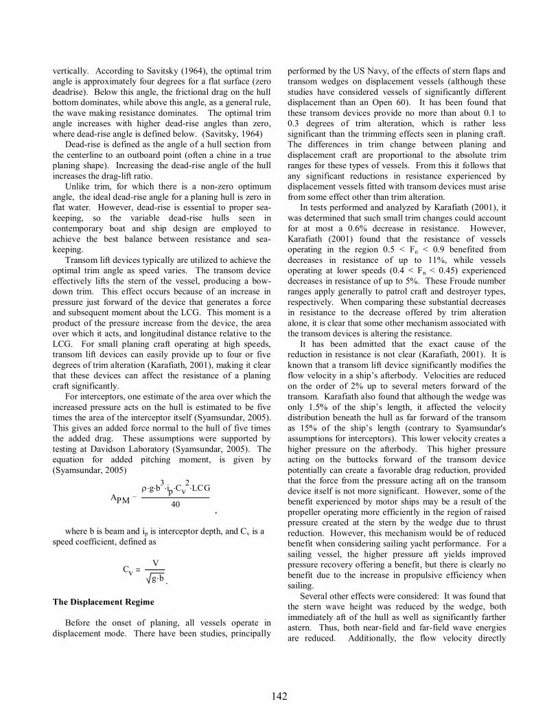
For interceptors, one estimate of the area over which the increased pressure acts on the hull is estimated to be five times the area of the interceptor itself (Syamsundar, 2005).This gives an added force normal to the hull of five times the added drag. These assumptions were supported by testing at Davidson Laboratory (Syamsundar, 2005). The equation for added pitching moment, is given by (Syamsundar, 2005)
APMg b3 ip Cv
2 LCG
40 ,
where b is beam and ip is interceptor depth, and Cv is a speed coefficient, defined as
Before the onset of planing, all vessels operate in displacement mode. There have been studies, principally
performed by the US Navy, of the effects of stern flaps and transom wedges on displacement vessels (although these studies have considered vessels of significantly different displacement than an Open 60). It has been found that these transom devices provide no more than about 0.1 to 0.3 degrees of trim alteration, which is rather less significant than the trimming effects seen in planing craft. The differences in trim change between planing and displacement craft are proportional to the absolute trim ranges for these types of vessels. From this it follows that any significant reductions in resistance experienced by displacement vessels fitted with transom devices must arise from some effect other than trim alteration.
In tests performed and analyzed by Karafiath (2001), it was determined that such small trim changes could account for at most a 0.6% decrease in resistance. However, Karafiath (2001) found that the resistance of vessels operating in the region 0.5 < Fn < 0.9 benefited from decreases in resistance of up to 11%, while vessels operating at lower speeds (0.4 < Fn < 0.45) experienced decreases in resistance of up to 5%. These Froude number ranges apply generally to patrol craft and destroyer types, respectively. When comparing these substantial decreases in resistance to the decrease offered by trim alteration alone, it is clear that some other mechanism associated with the transom devices is altering the resistance.
It has been admitted that the exact cause of the reduction in resistance is not clear (Karafiath, 2001). It is known that a transom lift device significantly modifies the flow velocity in a ship afterbody. Velocities are reduced on the order of 2% up to several meters forward of the transom. Karafiath also found that although the wedge was
h, it affected the velocity distribution beneath the hull as far forward of the transom
(contrary to Syamsundar's assumptions for interceptors). This lower velocity creates a higher pressure on the afterbody. This higher pressure acting on the buttocks forward of the transom device potentially can create a favorable drag reduction, provided that the force from the pressure acting aft on the transom device itself is not more significant. However, some of the benefit experienced by motor ships may be a result of the propeller operating more efficiently in the region of raised pressure created at the stern by the wedge due to thrust reduction. However, this mechanism would be of reduced benefit when considering sailing yacht performance. For a sailing vessel, the higher pressure aft yields improved pressure recovery offering a benefit, but there is clearly no benefit due to the increase in propulsive efficiency when sailing.
Several other effects were considered: It was found that the stern wave height was reduced by the wedge, bothimmediately aft of the hull as well as significantly farther astern. Thus, both near-field and far-field wave energies are reduced. Additionally, the flow velocity directly
CvV
g b .
142

increased. This increased flow velocity improves the separation of flow at the transom, thus allowing separation to occur at a lower speed than without the device. Finally,
lengthening of the ship the waterline is effectively increased 0.5% to 2.5% which further reduces wave
(Karafiath, 2001).
This section describes the equipment and methods used in analyzing the various configurations of the trim tab and interceptors on the model of the Open 60 Imagine.
This study utilized a one-tenth scale model of the Open 60 Imagine. The model originally was constructed for the 1995 thesis of Falls, Hutchings, and Ward. The body plan of Imagine appears in Appendix A. A discussion of the original construction of the model can be found in the 1995 thesis. The principal characteristics of Imagine can be seen in Table 1.
Imagine Principal Characteristics
60 ft 72 in
58.1 ft 69.72 in
22.21 ft 26.65 in
0.569 0.5690.357 0.3570.627 0.62728.44 ft aft FP 34.13 in aft FP
33 ft aft FP 39.6 in aft FP
29750 lbs (SW) 29.0 lbs (FW)
644.5 ft2 928.1 in^2
-1.22 ft Not to Scale0.47 ft 0.56 in
-0.203 ft -0.24 in
Over its 15-year life, the model had incurred considerable wear and tear, and a general refurbishing was necessary. Figure 2 shows the condition of the model at the beginning of this refurbishment. The first step was removal of the appendages that had been part of the
these tests. The model was then stripped of its original
transom, requiring repairs using a thickened epoxy fillet. The model was faired with an epoxy-based fairing filler. The aft buttocks and waterlines were also filled slightly where excessive sanding had produced a region of convexity. This convexity was the direct opposite of the effect developed by trim tabs or interceptors, so it was important to correct this and match ImagineSeveral iterations were made in fairing the hull, alternating between sanding and filling, in order to achieve the designed shape.
Open 60 Model Imagine Before Refurbishment
The model originally had been fitted with a structurethat allowed the model to be mounted to the yacht dynamometer that had been in use at that time. This testing utilized a different system, so modification of the model was required. Difficulties in the removal of the old structure resulted in damage to the hull planking. This damage was due to inherently weak edge bonds between the cedar-strip planking in addition to the accidental bonding of pieces of the structure to the planking. This damage evoked concern for the ability of the model to withstand the stresses of testing, especially with the new mounting system which, as designed, would transmit the towing force through the hull planking. The decision was made to repair the hull damage and then to reinforce the damaged areas and all other areas considered to be weak points.
The damage consisted of longitudinal cracks in the planking on the centerline. These cracks were repaired with thickened epoxy fairing compound on the exterior, which was then faired in the same manner as the hull. On the inner hull surface, thickened structural epoxy was used to fill the cracks. While the epoxy was still uncured, a three-inch-wide strip of fiberglass cloth was applied along the centerline in way of the damage and extending longitudinally along the three center compartments to
143
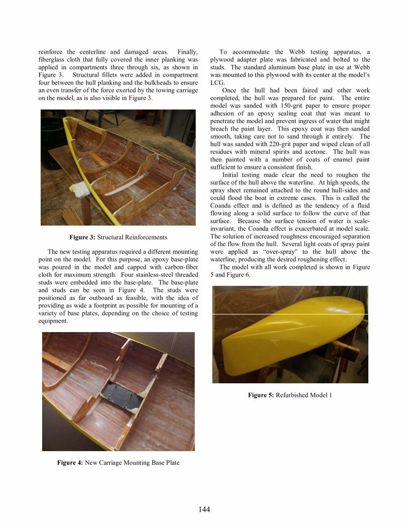
reinforce the centerline and damaged areas. Finally, fiberglass cloth that fully covered the inner planking was applied in compartments three through six, as shown in Figure 3. Structural fillets were added in compartment four between the hull planking and the bulkheads to ensure an even transfer of the force exerted by the towing carriage on the model, as is also visible in Figure 3.
Structural Reinforcements
The new testing apparatus required a different mounting point on the model. For this purpose, an epoxy base-plate was poured in the model and capped with carbon-fiber cloth for maximum strength. Four stainless-steel threaded studs were embedded into the base-plate. The base-plate and studs can be seen in Figure 4. The studs were positioned as far outboard as feasible, with the idea of providing as wide a footprint as possible for mounting of a variety of base plates, depending on the choice of testing equipment.
New Carriage Mounting Base Plate
To accommodate the Webb testing apparatus, a plywood adapter plate was fabricated and bolted to the studs. The standard aluminum base plate in use at Webb
LCG. Once the hull had been faired and other work
completed, the hull was prepared for paint. The entire model was sanded with 150-grit paper to ensure proper adhesion of an epoxy sealing coat that was meant to penetrate the model and prevent ingress of water that might breach the paint layer. This epoxy coat was then sanded smooth, taking care not to sand through it entirely. The hull was sanded with 220-grit paper and wiped clean of all residues with mineral spirits and acetone. The hull was then painted with a number of coats of enamel paint sufficient to ensure a consistent finish.
Initial testing made clear the need to roughen the surface of the hull above the waterline. At high speeds, the spray sheet remained attached to the round hull-sides and could flood the boat in extreme cases. This is called the Coanda effect and is defined as the tendency of a fluid flowing along a solid surface to follow the curve of that surface. Because the surface tension of water is scale-invariant, the Coanda effect is exacerbated at model scale. The solution of increased roughness encouraged separation of the flow from the hull. Several light coats of spray paint
-waterline, producing the desired roughening effect.
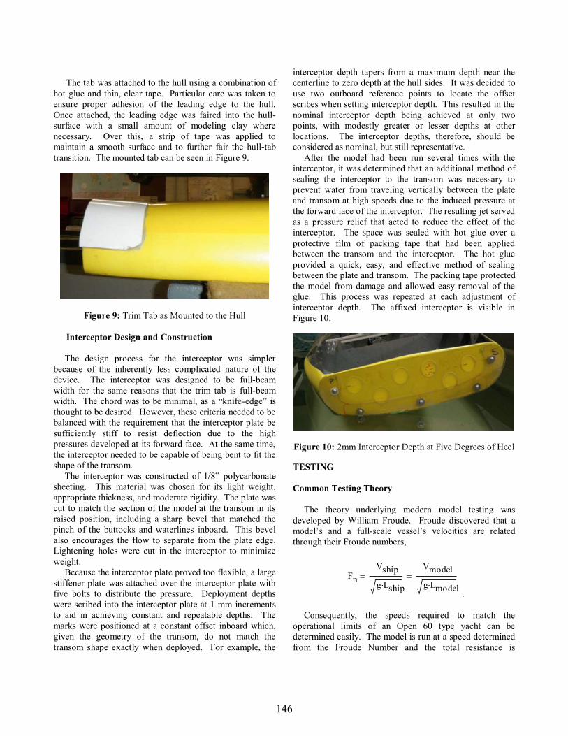
The model with all work completed is shown in Figure 5 and Figure 6.
Refurbished Model 1
144

Refurbished Model 2
A solid wedge was used in place of an adjustable tab. This decision was made because a wedge will behave just as would a trim tab, and also because the limited testing matrix made it more efficient simply to construct a single wedge rather than a more complex adjustable tab mechanism.
width is established by the beam of the vessel. This is a reasonable decision when considering the current use of transom wedges on larger powerboat designs which often feature full-beam-width wedges. Small planing craft often utilize two flaps of only 10-15% of the beam at the transom. However, the additional requirement of operating at multiple heel angles, and previous employment of tabs on Open 60s gave further support to the decision to construct the tab at full-inches at model scale and matches the approximate one-meter chord of trim tabs employed on the Farr designed Open 60s.
The angle of the tab was set at five degrees using information gleaned from Open 60 skippers. These skippers have cited an operational range of up to seven degrees and, therefore, five degrees was decided as a reasonable testing point.
The tab was constructed using the female mold shown in
Figure that afterbody, which was used as the male mold. This process ensured that the surface geometry of the trim tab would be a perfect match to the afterbody of the hull. The idea here is that at full scale the tabs should be shaped so that they would sit flush with the hull when retracted. This construction method produced the shape required to simulate this.
Trim Tab Lay-up
Continuing with construction, the depth and angle of the tab were established by two five-degree wooden wedges that were affixed to the tab at locations just inboard of the turn of the bilge, both port and starboard. The angle of five degrees at those locations gave a maximum depth at the
then placed on top of the model, and the void between the two was filled with a combination of foam and epoxy fairing compound. This gave a shape that matched the hull surface and a structure that would not deflect under the pressure developed by the tab. The leading edge of the tab was sanded to a sharp edge so that it would mount cleanly to the model with a minimal lip and preserve the desired flow effect.
To account for the buoyancy added by the tab, weights were added such that the tab would be neutrally buoyant. As such, no correction of model LCG was required. The hull-side surface of the tab can be seen in Figure 8, where the sharpened edge, weights, and wooden wedges that set the angle are all visible.
Hull-side Surface of Trim Tab
145
The tab was attached to the hull using a combination of hot glue and thin, clear tape. Particular care was taken to ensure proper adhesion of the leading edge to the hull. Once attached, the leading edge was faired into the hull-surface with a small amount of modeling clay where necessary. Over this, a strip of tape was applied to maintain a smooth surface and to further fair the hull-tab transition. The mounted tab can be seen in Figure 9.
Trim Tab as Mounted to the Hull
The design process for the interceptor was simpler because of the inherently less complicated nature of thedevice. The interceptor was designed to be full-beam width for the same reasons that the trim tab is full-beam
-thought to be desired. However, these criteria needed to be balanced with the requirement that the interceptor plate be sufficiently stiff to resist deflection due to the high pressures developed at its forward face. At the same time, the interceptor needed to be capable of being bent to fit the shape of the transom. The interceptor washeeting. This material was chosen for its light weight, appropriate thickness, and moderate rigidity. The plate was cut to match the section of the model at the transom in its raised position, including a sharp bevel that matched the pinch of the buttocks and waterlines inboard. This bevel also encourages the flow to separate from the plate edge. Lightening holes were cut in the interceptor to minimize weight. Because the interceptor plate proved too flexible, a large stiffener plate was attached over the interceptor plate with five bolts to distribute the pressure. Deployment depths were scribed into the interceptor plate at 1 mm increments to aid in achieving constant and repeatable depths. The marks were positioned at a constant offset inboard which,given the geometry of the transom, do not match the transom shape exactly when deployed. For example, the
interceptor depth tapers from a maximum depth near the centerline to zero depth at the hull sides. It was decided to use two outboard reference points to locate the offset scribes when setting interceptor depth. This resulted in the nominal interceptor depth being achieved at only two points, with modestly greater or lesser depths at other locations. The interceptor depths, therefore, should be considered as nominal, but still representative. After the model had been run several times with the interceptor, it was determined that an additional method of sealing the interceptor to the transom was necessary to prevent water from traveling vertically between the plate and transom at high speeds due to the induced pressure at the forward face of the interceptor. The resulting jet served as a pressure relief that acted to reduce the effect of the interceptor. The space was sealed with hot glue over a protective film of packing tape that had been applied between the transom and the interceptor. The hot glue provided a quick, easy, and effective method of sealing between the plate and transom. The packing tape protected the model from damage and allowed easy removal of the glue. This process was repeated at each adjustment of interceptor depth. The affixed interceptor is visible in Figure 10.
2mm Interceptor Depth at Five Degrees of Heel
The theory underlying modern model testing was developed by William Froude. Froude discovered that a model and a full-scale vessel are related through their Froude numbers,
.
Consequently, the speeds required to match the operational limits of an Open 60 type yacht can be determined easily. The model is run at a speed determined from the Froude Number and the total resistance is
146
measured by the testing apparatus. The measured resistance, RT, is the total resistance of the model. An arbitrary resistance coefficient, Cx, can be defined through the relationship:
,
where RxVVessel resistance can be divided into two major components frictional resistance and residuary resistance allowing a similar division of the total resistance coefficient as
CT CR CF .
The residuary resistance coefficient CR is the same at both full and model scales. The residuary resistance is dominated by wavemaking resistance, follows Froude scaling, and can be found by solving the resistance-coefficient equation above for Rx, where an R, for residuary, would take the place of the arbitrary x-subscripts. Unlike the residuary resistance, the frictional resistance coefficient of the model differs from that of the ship. Consequently, the frictional resistance must be backed out of the total measured resistance of the model. Frictional resistance, or viscous drag, is driven by the Reynolds number . The frictional resistance coefficient is calculated easily using the International Towing Tank Conference
is given by
,
where Rn is the Reynolds number. The Reynolds number is determined from
RnV L
,
where V is the vessel speed, L is its waterline length, and the kinematic viscosity of the fluid (water). Once the
F have been determined, the frictional component of CT can be subtracted to leave the residuary component CR, from which RR can be determined. The total resistance at full scale, RT, is determined by adding the frictional resistance of the full scale vessel to the residuary resistance RR, where the frictional resistance is calculated in the same manner as
that of the model, as described previously.
The effect of trim-altering devices on a vessel when heeled is of considerable interest because sailing yachts are always heeled to some degree while underway. A priority of this research was testing of the model with heel, and measurements were made at heel angles of zero, five, and ten degrees. These heel angles cover the range often experienced by Open 60s when operating down-wind, where transom-lift devices are supposed most effective. In their research, Falls, et al. (1995) witnessed the beginning of planing at approximately 8 ft/s which corresponds to a boat speed of 15 knots. It was desired to conduct several tests within both the displacement and planing regimes. Modern Open 60s can reach speeds approaching 40 knots and often operate near 30 knots. An ideal test matrix would have an upper limit at about 30 knots of boat speed, but the maximum carriage speed in Robinson Model Basin of about 15 ft/s corresponds to a full-scale speed of about 28 knots. This allowed several tests to be made in the planing regime, where the greatest benefit of trim tabs and interceptors is to be expected. After initial tests, the maximum speed was reduced to 13.9 ft/s for the bare-hull and zero-heel studies. The speed was reduced further for several heeled conditions because the model took on water at higher speeds or when heeled, especially with transom devices employed. The model was tested in three basic configurations. These included the bare hull, with interceptor added, and with trim tab added. With the interceptor affixed, three plate deployment depths were tested. Merf Owen of Owen Clarke Design stated that one to three centimeters of interceptor deployment is typical (Boyd, 2009). These values correspond 0.0394 to 0.118 inches at model scale, or more simply 1 3 mm. The depths will be referenced in millimeters for simplicity henceforth. Previous model tests for trim tabs on planing craft have investigated tab angles as large as 15 degrees. However, the tabs on Open 60s have considerably higher chords than do lower range of tab operation and five degrees is within the typical operational range, according to successful Open 60 sailor Loick Peyron (Boyd, 2008). During model testing measurements of resistance, trim, and sinkage were taken. This does not constitute a traditional sailing yacht test, but the proper equipment for this type of testing was unavailable. Additionally, a full sailing yacht test would have increased the size of the test matrix significantly, making it an extensive task to acquire the required data. Because the condition for deployment of transom lift devices is off the wind, a full sailing yacht test is not necessary. The model was free to sink and trim but was restricted in yaw and heel. All runs were performed at zero yaw. In reality, yaw allows some cross flow over the
147

transom and reduces the effect of a transom device slightly, but it was not expected that the testing would suffer significant negative effects from the omission of yaw and leeway. The model was towed from the longitudinal center of gravity with the tow point mounted as low in the hull as feasible. In order to simplify testing, weights were not moved to account for varying trimming moments due to the rig and sails. This decision was made because of the comparative nature of the testing. When analyzing the results absolutely, one must consider that the bow-down trim induced by the transom devices would be in addition to the rig-trimming moment-induced trim.
was a Hydronautics magnetic inductance force block with a twenty pound nominal capacity. Trim was measured with a Shaevitz R30A rotary variable differential transformer (RVDT), which produces an output voltage from a rotary motion input. This voltage was calibrated to return an angular displacement. A TRD SH2500VD linear encoder attached to a rack was used to measure sinkage. Heel angle was set by a variable-angle fixture. The mount had nominal heel increments including zero, five, and ten degrees. The heave staff, force block, trim RVDT, and sinkage linear encoder are visible in Figure 11.
Heave Staff with Measurement Devices
Testing was performed at the configurations listed in
Table 2. The speeds tested varied from 1.068 ft/s to 13.89 ft/s, in increments of 1.068 ft/s, with slower maximum speeds for deep interceptor deployments, the trim tab, and higher heel angles. These speeds correspond to full-scale boat-speeds of 2 to 26 knots.
Testing Matrix
Bare 0, 5, 10 1.07-13.891mm Interceptor 0, 5, 10 1.07-11.752mm Interceptor 0, 5, 10 1.07-10.683mm Interceptor 0, 5, 10 1.07-10.685deg Trim Tab 0, 5, 10 1.07-10.68
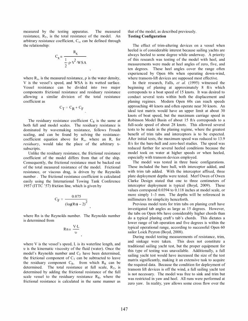
Results for zero, five, and ten degrees of heel are illustrated in Figure 12, Figure 13, and Figure 14. Thesefigures show values for resistance, sinkage, and trim as functions of the Froude number for each model configuration. The graphs become difficult to read in small half-page-width and grey-scale, but displaying all data together was an objective in order to highlight their relationships. Figure 15 shows the results for the bare-hull configuration at zero heel, together with data from Falls, Hutchings, and Ward (1995). In all Figures, interceptor depths of one, two, and three millimeters are denoted as 1mm, 2mm, and 3mm, respectively. The five-degree trim tab configuration is denoted as 5deg. The complete set of results is tabulated in Appendix B. For the error analysis performed, please refer to the original thesis paper.
148

Data for Resistance, Trim, and Sinkage of all Configurations at Zero Heel
As is evident from Figure 15, resistance values for the bare hull at zero heel match the trends observed by Falls, Hutchings, and Ward (1995). The large disparity between their results and the ones presented here is likely a result of the large appendages that were present in their tests. Those appendages, which include a keel fin, bulb, and twin rudders, may be expected to have contributed to a large portion of the greater resistance measured by Falls, et al.The foils were quite large, in both plan form and thickness, when compared to the appendages used on Open 60s today.
Data for Resistance, Trim, and Sinkage of All Configurations at Five Degrees of Heel
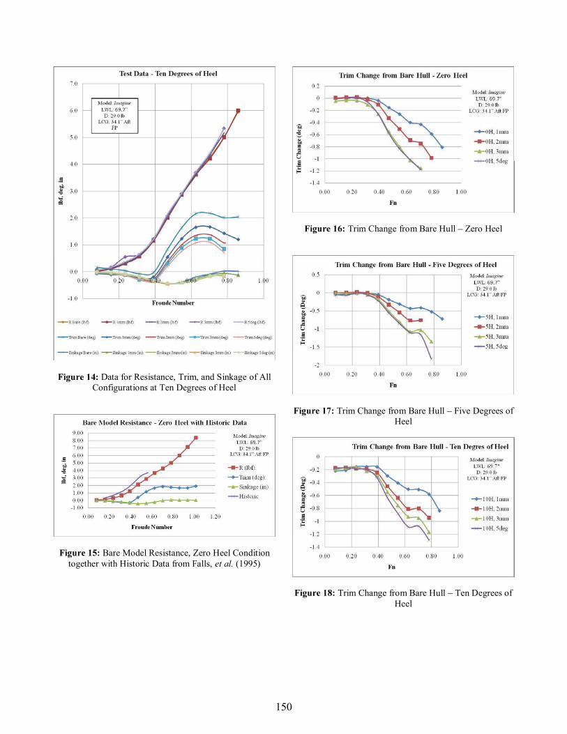
It is clear that interceptors markedly alter the trim of the vessel. At Fn = 0.70, where trim is nearly at its maximum for all cases, the 3 mm interceptor results in a trim reduction of approximately 60% relative to the bare hull. The trim tab also significantly reduces trim, but it must be considered that the depth at the transom of the trim tab is nearly four times that of the deepest interceptor, the 3 mm deployment, and the tab nearly matched the trim effects of that interceptor deployment. In fact, the trim of the model with the tab is nearly identical to that of the 3mm interceptor at zero and five degrees of heel. At ten degrees of heel, the tab trims the model more than the 3mm interceptor, making it clear that considerably less interceptor depth is needed in order to develop lift equal to that of a trim tab. Figure 16, Figure 17, and Figure 18display the trim effects for heel angles of zero, five, and ten degrees, respectively. It can be seen that the deepest interceptor deployment of 3 mm results in the greatest change in trim for interceptors, and that the five degree wedge induces the greatest change to trim of all variants. See Appendix C for all trim delta/difference calculations.
149
Data for Resistance, Trim, and Sinkage of All Configurations at Ten Degrees of Heel
Bare Model Resistance, Zero Heel Condition together with Historic Data from Falls, et al. (1995)
Trim Change from Bare Hull Zero Heel
Trim Change from Bare Hull Five Degrees of Heel
Trim Change from Bare Hull Ten Degrees of Heel
150
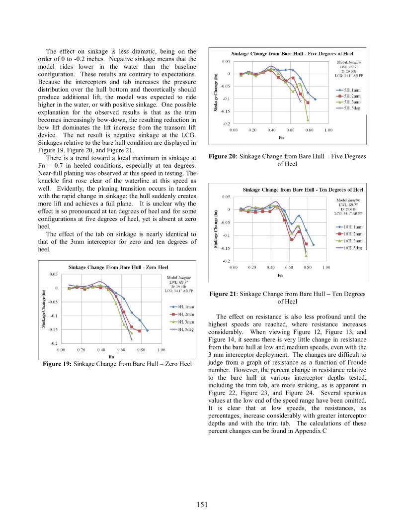
The effect on sinkage is less dramatic, being on the order of 0 to -0.2 inches. Negative sinkage means that the model rides lower in the water than the baseline configuration. These results are contrary to expectations. Because the interceptors and tab increases the pressure distribution over the hull bottom and theoretically should produce additional lift, the model was expected to ride higher in the water, or with positive sinkage. One possible explanation for the observed results is that as the trim becomes increasingly bow-down, the resulting reduction in bow lift dominates the lift increase from the transom lift device. The net result is negative sinkage at the LCG. Sinkages relative to the bare hull condition are displayed in Figure 19, Figure 20, and Figure 21. There is a trend toward a local maximum in sinkage at Fn = 0.7 in heeled conditions, especially at ten degrees. Near-full planing was observed at this speed in testing. The knuckle first rose clear of the waterline at this speed as well. Evidently, the planing transition occurs in tandem with the rapid change in sinkage: the hull suddenly creates more lift and achieves a full plane. It is unclear why the effect is so pronounced at ten degrees of heel and for some configurations at five degrees of heel, yet is absent at zero heel. The effect of the tab on sinkage is nearly identical to that of the 3mm interceptor for zero and ten degrees of heel.
Sinkage Change from Bare Hull Zero Heel
Sinkage Change from Bare Hull Five Degrees of Heel
: Sinkage Change from Bare Hull Ten Degrees of Heel
The effect on resistance is also less profound until the highest speeds are reached, where resistance increases considerably. When viewing Figure 12, Figure 13, and Figure 14, it seems there is very little change in resistance from the bare hull at low and medium speeds, even with the 3 mm interceptor deployment. The changes are difficult to judge from a graph of resistance as a function of Froude number. However, the percent change in resistance relative to the bare hull at various interceptor depths tested, including the trim tab, are more striking, as is apparent in Figure 22, Figure 23, and Figure 24. Several spurious values at the low end of the speed range have been omitted. It is clear that at low speeds, the resistances, as percentages, increase considerably with greater interceptor depths and with the trim tab. The calculations of these percent changes can be found in Appendix C
151
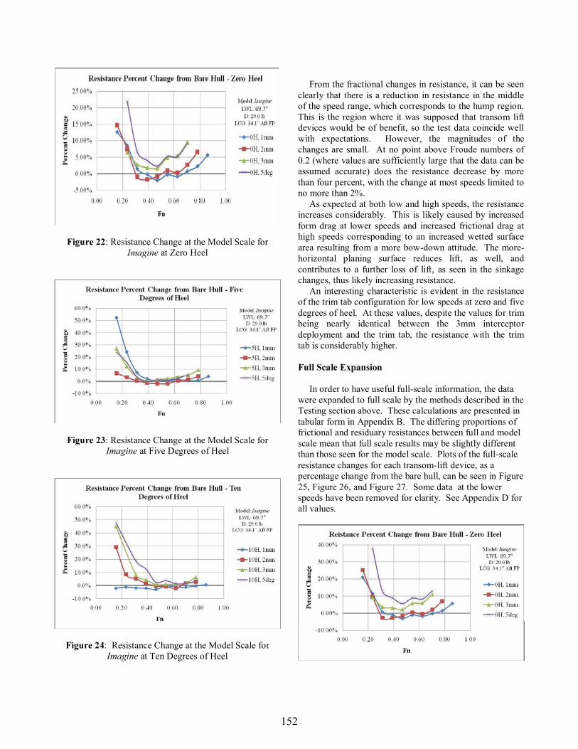
: Resistance Change at the Model Scale for Imagine at Zero Heel
: Resistance Change at the Model Scale for Imagine at Five Degrees of Heel
: Resistance Change at the Model Scale for Imagine at Ten Degrees of Heel
From the fractional changes in resistance, it can be seen clearly that there is a reduction in resistance in the middle of the speed range, which corresponds to the hump region. This is the region where it was supposed that transom lift devices would be of benefit, so the test data coincide well with expectations. However, the magnitudes of the changes are small. At no point above Froude numbers of 0.2 (where values are sufficiently large that the data can be assumed accurate) does the resistance decrease by more than four percent, with the change at most speeds limited to no more than 2%. As expected at both low and high speeds, the resistance increases considerably. This is likely caused by increased form drag at lower speeds and increased frictional drag at high speeds corresponding to an increased wetted surface area resulting from a more bow-down attitude. The more-horizontal planing surface reduces lift, as well, andcontributes to a further loss of lift, as seen in the sinkage changes, thus likely increasing resistance. An interesting characteristic is evident in the resistance of the trim tab configuration for low speeds at zero and five degrees of heel. At these values, despite the values for trim being nearly identical between the 3mm interceptor deployment and the trim tab, the resistance with the trim tab is considerably higher.
In order to have useful full-scale information, the data were expanded to full scale by the methods described in the Testing section above. These calculations are presented in tabular form in Appendix B. The differing proportions of frictional and residuary resistances between full and model scale mean that full scale results may be slightly different than those seen for the model scale. Plots of the full-scale resistance changes for each transom-lift device, as a percentage change from the bare hull, can be seen in Figure 25, Figure 26, and Figure 27. Some data at the lower speeds have been removed for clarity. See Appendix D for all values.
152
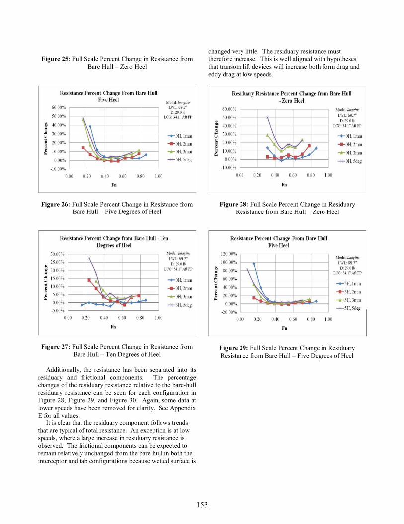
: Full Scale Percent Change in Resistance from Bare Hull Zero Heel
Full Scale Percent Change in Resistance from Bare Hull Five Degrees of Heel
Full Scale Percent Change in Resistance from Bare Hull Ten Degrees of Heel
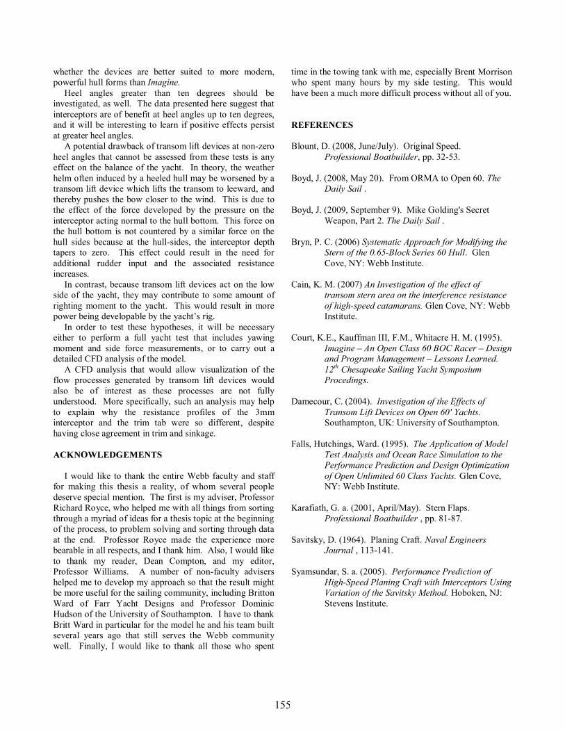
Additionally, the resistance has been separated into its residuary and frictional components. The percentage changes of the residuary resistance relative to the bare-hull residuary resistance can be seen for each configuration in Figure 28, Figure 29, and Figure 30. Again, some data at lower speeds have been removed for clarity. See Appendix E for all values. It is clear that the residuary component follows trends that are typical of total resistance. An exception is at low speeds, where a large increase in residuary resistance is observed. The frictional components can be expected to remain relatively unchanged from the bare hull in both the interceptor and tab configurations because wetted surface is
changed very little. The residuary resistance must therefore increase. This is well aligned with hypotheses that transom lift devices will increase both form drag and eddy drag at low speeds.
Full Scale Percent Change in Residuary Resistance from Bare Hull Zero Heel
Full Scale Percent Change in Residuary Resistance from Bare Hull Five Degrees of Heel
153

Full Scale Percent Change in Residuary Resistance from Bare Hull Ten Degrees of Heel
The consistent trends observed in these experiments suggest that the data are valid and repeatable. At low speeds, some uncertainty arises from the size of the measured values relative to the noise associated with the various electronics and mechanics of the model carriage and other equipment. Additionally, the random error of the instruments comes into play. These values can be found in Appendix B for comparison to total resistance.
Based on the results presented in this thesis, neither interceptors nor this particular trim tab design are recommended for use on the Open 60 Imagine. There was a decrease in resistance and it is known that even a small benefit can be of massive importance in high-tech racing yachts. However, the magnitude of the benefits versus the uncertainty of the testing, especially when considering scaling effects on transom lift devices, make it difficult to justify the alteration of a yacht like Imagine. However, this surely does not necessarily preclude the devices from having merit. The data show sufficient promise that, when designed in concert with an appropriate hull form, interceptors may be of significant value. Similarly, trim tabs offer a means of obtaining considerable correction to trim which could be highly beneficial. Several observations suggest that Imagine, in particular, is not a good candidate for transom lift devices. Even at high speeds in the bare-hull configuration, bow and knuckle barely clear the waterline. This suggests that little or no trim correction is required for the hull, as a further lowering of the bow will result only in an increased wetted surface area and decreased hydrodynamic lift
relative to the already nearly horizontal planing surface.
detrimental. This is evidenced in that, in both speed ranges above and below the hump region, resistance increases markedly. The aforementioned effect of increased wetted surface area and reduced lift at the bow is thought to be responsible for these increases. Imagine would likely need to have higher volume forward in order to truly benefit from transom lift devices. Transom lift devices typically are installed on traditional planing-craft shapes and clearly have beneficial effects for these hull forms. Current designs of Open 60s are trending increasingly towards these planing hull shapes. The aft chines seen on most new Open 60s and their flatter hulls are examples of this trend. It is worth considering that Imagine,form, might differ too much from a planing hull shape to benefit drastically from a transom lift device. One particularly interesting effect is related to heel angle. It can be seen from Figure 23 and Figure 24 that the resistance curves flatten noticeably at five and ten degrees of heel. This flattening suggests a greater operational range over which interceptors may be of benefit, although the magnitude of the benefit is decreased slightly relative to the zero-heel condition. This suggests that interceptors may retain their appeal even when the yacht is subject to heel. It is clear that transom lift devices have a significant effect on the running trim of a vessel with only a minimal cost in resistance across the majority of speed range. Given the large induced bow-down attitude, it is surprising that deeper interceptor deployment depths did not lead to greater resistance than they did. This suggests that some unknown benefit may arise from the interceptors having altered the flow under the hull, beyond changes in resistance from trim changes alone. It is possible that these benefits offset the negative impact of the yacht being run at too low a trim angle, which could explain the surprising lack of change in resistance despite substantial changes in running trim. Similarly, it is unclear why the trim tab configuration, which gave nearly identical values for trim and sinkage at many speeds, had so much greater resistance than the 3 millimeter interceptor. Understanding whether this trend continues with smaller tabs and shallower interceptors requires further testing. If the trend does continue, it appears that tabs are generally less effective than interceptors because tabs cause higher resistance at all speeds under all operational conditions and, tabs are inherently more complicated and heavier with regard to installation at full scale.
Transom lift devices certainly merit further investigation. Studies should be conducted to determine
154
whether the devices are better suited to more modern,powerful hull forms than Imagine. Heel angles greater than ten degrees should be investigated, as well. The data presented here suggest that interceptors are of benefit at heel angles up to ten degrees, and it will be interesting to learn if positive effects persist at greater heel angles.
A potential drawback of transom lift devices at non-zero heel angles that cannot be assessed from these tests is any effect on the balance of the yacht. In theory, the weather helm often induced by a heeled hull may be worsened by a transom lift device which lifts the transom to leeward, and thereby pushes the bow closer to the wind. This is due to the effect of the force developed by the pressure on the interceptor acting normal to the hull bottom. This force on the hull bottom is not countered by a similar force on the hull sides because at the hull-sides, the interceptor depth tapers to zero. This effect could result in the need for additional rudder input and the associated resistance increases. In contrast, because transom lift devices act on the low side of the yacht, they may contribute to some amount of righting moment to the yacht. This would result in more pow In order to test these hypotheses, it will be necessary either to perform a full yacht test that includes yawing moment and side force measurements, or to carry out a detailed CFD analysis of the model. A CFD analysis that would allow visualization of the flow processes generated by transom lift devices would also be of interest as these processes are not fully understood. More specifically, such an analysis may help to explain why the resistance profiles of the 3mm interceptor and the trim tab were so different, despite having close agreement in trim and sinkage.
I would like to thank the entire Webb faculty and staff for making this thesis a reality, of whom several people deserve special mention. The first is my adviser, Professor Richard Royce, who helped me with all things from sorting through a myriad of ideas for a thesis topic at the beginning of the process, to problem solving and sorting through data at the end. Professor Royce made the experience more bearable in all respects, and I thank him. Also, I would like to thank my reader, Dean Compton, and my editor, Professor Williams. A number of non-faculty advisers helped me to develop my approach so that the result might be more useful for the sailing community, including Britton Ward of Farr Yacht Designs and Professor Dominic Hudson of the University of Southampton. I have to thank Britt Ward in particular for the model he and his team built several years ago that still serves the Webb community well. Finally, I would like to thank all those who spent
time in the towing tank with me, especially Brent Morrison who spent many hours by my side testing. This would have been a much more difficult process without all of you.
Blount, D. (2008, June/July). Original Speed. Professional Boatbuilder, pp. 32-53.
Boyd, J. (2008, May 20). From ORMA to Open 60. The Daily Sail .
Boyd, J. (2009, September 9). Mike Golding's Secret Weapon, Part 2. The Daily Sail .
Bryn, P. C. (2006) Systematic Approach for Modifying the Stern of the 0.65-Block Series 60 Hull. Glen Cove, NY: Webb Institute.
Cain, K. M. (2007) An Investigation of the effect of transom stern area on the interference resistance of high-speed catamarans. Glen Cove, NY: Webb Institute.
Court, K.E., Kauffman III, F.M., Whitacre H. M. (1995). Imagine An Open Class 60 BOC Racer Design
and Program Management Lessons Learned. 12th Chesapeake Sailing Yacht Symposium Procedings.
Damecour, C. (2004). Investigation of the Effects of Transom Lift Devices on Open 60' Yachts.Southampton, UK: University of Southampton.
Falls, Hutchings, Ward. (1995). The Application of Model Test Analysis and Ocean Race Simulation to the Performance Prediction and Design Optimization of Open Unlimited 60 Class Yachts. Glen Cove, NY: Webb Institute.
Karafiath, G. a. (2001, April/May). Stern Flaps. Professional Boatbuilder , pp. 81-87.
Savitsky, D. (1964). Planing Craft. Naval Engineers Journal , 113-141.
Syamsundar, S. a. (2005). Performance Prediction of High-Speed Planing Craft with Interceptors Using Variation of the Savitsky Method. Hoboken, NJ: Stevens Institute.
155

Body Plan of the Open 60 Imagine Model Data Calibration and Correction Wetted Surface Areas and Expansion to Full Scale
Model Resistance, Trim, and Sinkage Deltas and Percent Differences from Bare Hull
Full Scale Total Resistance Deltas and Percent Differences from Bare Hull
Full Scale Residuary Resistance Deltas and Percent Differences from Bare Hull
156