Embed Size (px)
Citation preview
AUTOMATIC CAR WASH
Machine Operation Manual
JETAGE GARAGE EQUIPMENTSHead Office: B-74, IInd Floor, Phase – II Naraina Industrial Area, New Delhi – 110028 (INDIA) Telephone:
+91-11-25897389, 25897528 Fax: +91-11-25897485 Mobile: +91-9810292921, 9212743900 Email:
[email protected] Service Email:[email protected] Website: www.jetageworld.com Service Helpline No: +91-1125844166, 9212743920, 9212743903
GENERAL OPERATIONAL MANUAL
1. Be sure the operator fully understand how to operate. 2. Be sure there are no any passenger and obstacle before start.3. Be sure there are no any stumbling block around the machine or any pipe or cable. 4. Operator should stand by the control panel if there are any emergency, please stop the machine
immediately.5. The machine based on 220v, 3 phase electric power, please do not touch the control panel and
element with wet hand, never spray water to the control panel.6. Turn off the power before machine maintenance or repair. 7. Turn off the power when out of business hour or thunder.8. Do not use any combustibility sprayer around the machine because these sprayer can easy to
cause fire. 9. Do not use iron or copper wire to instead of fuse, it should be repaired with suitable fuse,
otherwise it will easy to cause fire. 10.Do not leave anything on or in the control panel box. 11.Do not touch or change anything in the control panel.12.The control panel door and button door should be closed during operation. 13.Do not open the control panel door in raining day.14.Be sure the car body situation and tire pressure before start. 15.Be sure the driver knows the attend items before start. 16.Daily maintenance before machine running.
1) Clean all of the photoelectric sensor surface. 2) Lubricate the chain for smooth running. 3) Check the detergent volume. 4) Check the 3 points combination.5) Check the water supply.6) Check the air compressor.
P.S : Our company will not take responsibility if there are not any reason that the operator do not follow the above instruction and caused any damage.

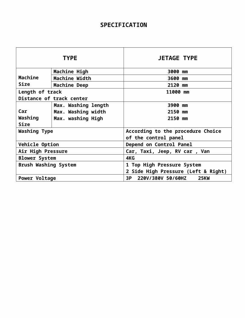
SPECIFICATION
TYPE JETAGE TYPE
Machine Size
Machine High 3000 mmMachine Width 3600 mmMachine Deep 2120 mm
Length of track Distance of track center
11000 mm
Car Washing Size
Max. Washing lengthMax. Washing width Max. washing High
3900 mm 2150 mm2150 mm
Washing Type According to the procedure Choice of the control panel
Vehicle Option Depend on Control Panel Air High Pressure Car, Taxi, Jeep, RV car , VanBlower System 4KGBrush Washing System 1 Top High Pressure System
2 Side High Pressure (Left & Right)Power Voltage 3P 220V/380V 50/60HZ 25KW
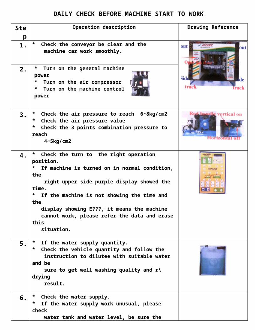
DAILY CHECK BEFORE MACHINE START TO WORK
Step Operation description Drawing Reference
1. * Check the conveyor be clear and the machine car work smoothly.
2. * Turn on the general machine power * Turn on the air compressor * Turn on the machine control power
3. * Check the air pressure to reach 6~8kg/cm2* Check the air pressure value * Check the 3 points combination pressure to reach 4~5kg/cm2
4. * Check the turn to the right operation position. * If machine is turned on in normal condition, the right upper side purple display showed the time.* If the machine is not showing the time and the display showing E???, it means the machine cannot work, please refer the data and erase this situation.
5. * If the water supply quantity.* Check the vehicle quantity and follow the instruction to dilutee with suitable water and be sure to get well washing quality and r\drying result.
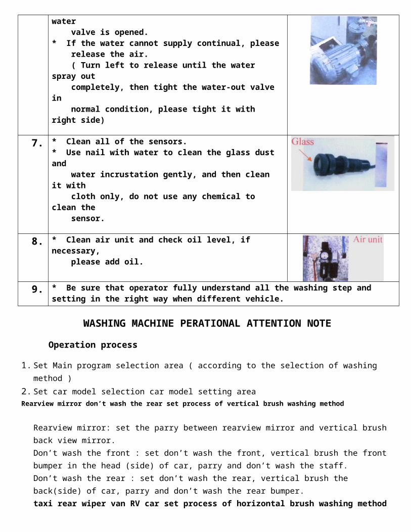
6. * Check the water supply. * If the water supply work unusual, please check water tank and water level, be sure the water valve is opened. * If the water cannot supply continual, please release the air. ( Turn left to release until the water spray out completely, then tight the water-out valve in normal condition, please tight it with right side)
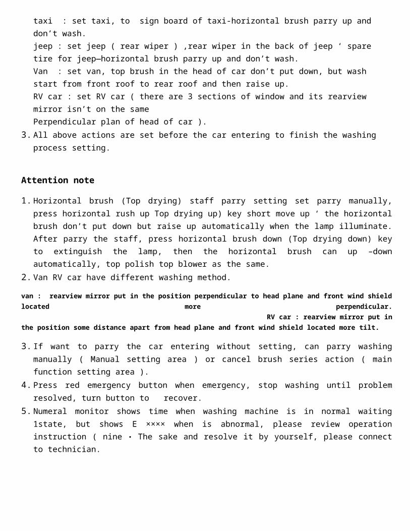
7. * Clean all of the sensors. * Use nail with water to clean the glass dust and water incrustation gently, and then clean it with cloth only, do not use any chemical to clean the sensor.
8. * Clean air unit and check oil level, if necessary, please add oil.

9. * Be sure that operator fully understand all the washing step and setting in the right way when different vehicle.
WASHING MACHINE PERATIONAL ATTENTION NOTE
Operation process
1. Set Main program selection area ( according to the selection of washing method )
2. Set car model selection car model setting area Rearview mirror don’t wash the rear set process of vertical brush washing method
Rearview mirror: set the parry between rearview mirror and vertical brush back view mirror. Don’t wash the front : set don’t wash the front, vertical brush the front bumper in the head (side) of car, parry and don’t wash the staff. Don’t wash the rear : set don’t wash the rear, vertical brush the back(side) of car, parry and don’t wash the rear bumper. taxi rear wiper van RV car set process of horizontal brush washing method taxi : set taxi, to sign board of taxi-horizontal brush parry up and don’t wash.jeep : set jeep ( rear wiper ) ,rear wiper in the back of jeep ‘ spare tire for jeep—horizontal brush parry up and don’t wash. Van : set van, top brush in the head of car don’t put down, but wash start from front roof to rear roof and then raise up. RV car : set RV car ( there are 3 sections of window and its rearview mirror isn’t on the same Perpendicular plan of head of car ).
3. All above actions are set before the car entering to finish the washing process setting.
Attention note
1. Horizontal brush (Top drying) staff parry setting set parry manually, press horizontal rush up Top drying up) key short move up ‘ the horizontal brush don’t put down but raise up automatically when the lamp illuminate. After parry the staff, press horizontal brush down (Top drying down) key to extinguish the lamp, then the horizontal brush can up –down automatically, top polish top blower as the same.
2. Van RV car have different washing method.
van : rearview mirror put in the position perpendicular to head plane and front wind shield located more perpendicular. RV car : rearview mirror put in the position some distance apart from head plane and front wind shield located more tilt.
3. If want to parry the car entering without setting, can parry washing manually ( Manual setting area ) or cancel brush series action ( main function setting area ).
4. Press red emergency button when emergency, stop washing until problem resolved, turn button to recover.
5. Numeral monitor shows time when washing machine is in normal waiting 1state, but shows E ×××× when is abnormal, please review operation instruction ( nine • The sake and resolve it by yourself, please connect to technician.
JETAGE WASH CONTROL PANEL INSTRUCTION
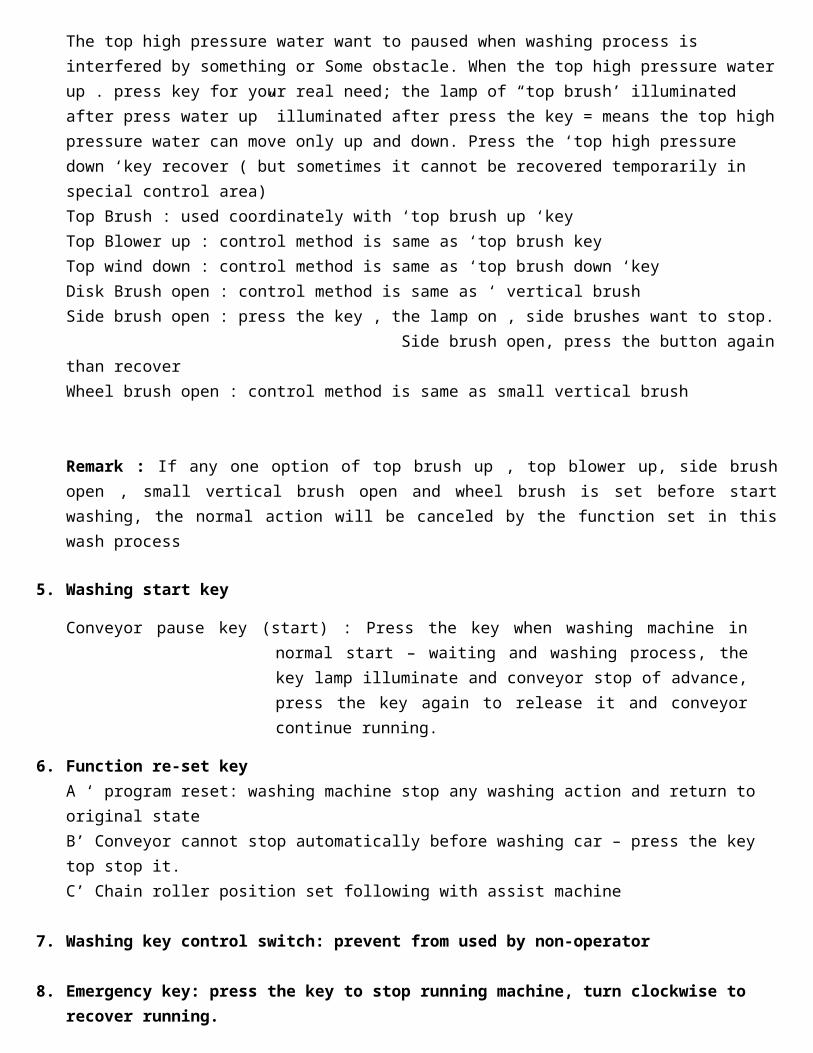
1. Main Function Option
Program 1 : Brush washing ; Blow (Rinse)Program 2 : High pressure water ; Brush washing ; Wax +BlowProgram 3 Brush washing ; Blow Program 4 Blow Rollover when dry
2. Main Function Series Washing
Top brush cancle : Cancle Normal Top high pressure function Side brush cancle : Cancle Normal up-side high pressure function Small brush cancle : Cancle Normal down-side high pressure function Top Blower cancle : cancle Top blower function Disk Brush cancle : Cancle Normal disk brush function
3. Car Model Function
Car : Top Brush wash all Taxi : Top Brush no wash roof Jeep : Top Brush no wash rear Van : Top Brush no wash rear and front Front no wash : Side brush front no wash Rear no wash : Side brush rear no wash
4. Manual Setting Area :
Top brush up The top high pressure water want to paused when washing process is interfered by something or Some obstacle. When the top high pressure water up . press key for your real need; the lamp of “top brush’ illuminated after press water up” illuminated after press the key = means the top high pressure water can move only up and down. Press the ‘top high pressure down ‘key recover ( but sometimes it cannot be recovered temporarily in special control area) Top Brush : used coordinately with ‘top brush up ‘key Top Blower up : control method is same as ‘top brush keyTop wind down : control method is same as ‘top brush down ‘key Disk Brush open : control method is same as ‘ vertical brush Side brush open : press the key , the lamp on , side brushes want to stop. Side brush open, press the button again than recover Wheel brush open : control method is same as small vertical brush
Remark : If any one option of top brush up , top blower up, side brush open , small vertical brush open and wheel brush is set before start washing, the normal action will be canceled by the function set in this wash process
5. Washing start key
Conveyor pause key (start) : Press the key when washing machine in normal start – waiting and washing process, the key lamp illuminate and conveyor stop of advance, press the key again to release it and conveyor continue running.
6. Function re-set keyA ‘ program reset: washing machine stop any washing action and return to original stateB’ Conveyor cannot stop automatically before washing car – press the key top stop it.C’ Chain roller position set following with assist machine
7. Washing key control switch: prevent from used by non-operator
8. Emergency key: press the key to stop running machine, turn clockwise to recover running.
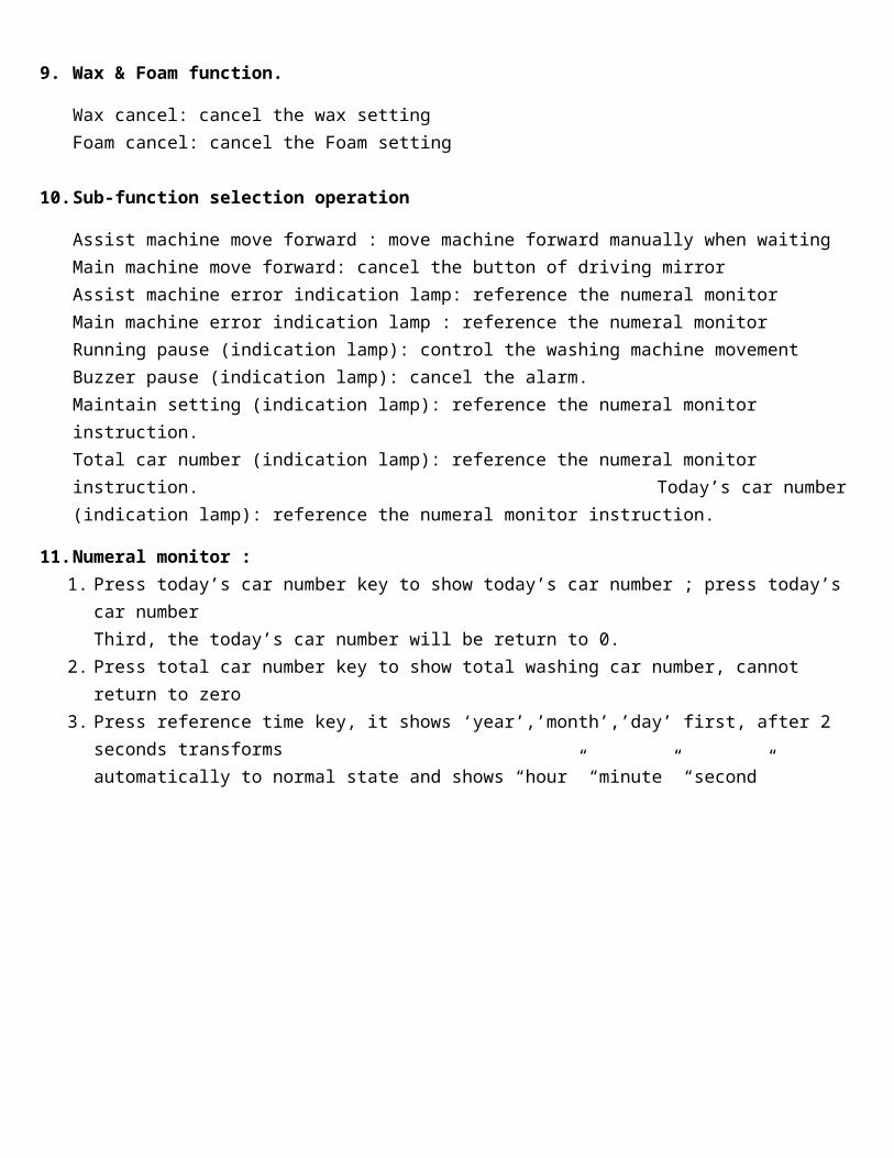
9. Wax & Foam function.
Wax cancel: cancel the wax settingFoam cancel: cancel the Foam setting
10. Sub-function selection operation
Assist machine move forward : move machine forward manually when waitingMain machine move forward: cancel the button of driving mirror Assist machine error indication lamp: reference the numeral monitor Main machine error indication lamp : reference the numeral monitorRunning pause (indication lamp): control the washing machine movementBuzzer pause (indication lamp): cancel the alarm. Maintain setting (indication lamp): reference the numeral monitor instruction.Total car number (indication lamp): reference the numeral monitor instruction. Today’s car number (indication lamp): reference the numeral monitor instruction.
11. Numeral monitor : 1. Press today’s car number key to show today’s car number ; press today’s car number
Third, the today’s car number will be return to 0.2. Press total car number key to show total washing car number, cannot return to zero 3. Press reference time key, it shows ‘year’,’month’,’day’ first, after 2 seconds transforms
automatically to normal state and shows “hour” “minute” “second”
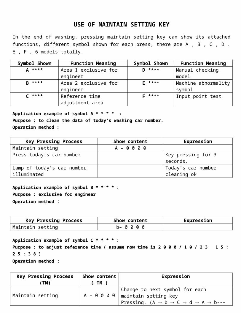
USE OF MAINTAIN SETTING KEY
In the end of washing, pressing maintain setting key can show its attached functions, different symbol shown for each press, there are A , B , C , D . E , F , 6 models totally.
Symbol Shown Function Meaning Symbol Shown Function MeaningA **** Area 1 exclusive for engineer D **** Manual checking model B **** Area 2 exclusive for engineer E **** Machine abnormality
symbol C **** Reference time adjustment area F **** Input point test
Application example of symbol A * * * * : Purpose : to clean the data of today’s washing car number. Operation method :
Key Pressing Process Show content Expression Maintain setting A – 0 0 0 0 Press today’s car number Key pressing for 3 seconds. Lamp of today’s car number illuminated Today’s car number cleaning ok
Application example of symbol B * * * * :Purpose : exclusive for engineerOperation method :
Key Pressing Process Show content Expression Maintain setting b– 0 0 0 0
Application example of symbol C * * * * :Purpose : to adjust reference time ( assume now time is 2 0 0 0 / 1 0 / 2 3 1 5 : 2 5 : 3 8 )Operation method :
Key Pressing Process (TM) Show content( TM )
Expression
Maintain setting A – 0 0 0 0 Change to next symbol for each maintain setting key Pressing. (A b C d A b---cycle )
Maintain setting b 0 0 0 0Maintain setting C 0 0 0 0 Enter to time setting after 1 second.
Blink state 0 01 0 2 3Left 2 orders represent year, middle 2 orders represent month, right 2 orders represent day
Blink state 0 01 0 2 3 Press arrow to transfer blink state to modification position.
+key 0 01 0 2 3 Plus - °-key 0 00 9 2 3 Minus - °Dual host shift 1 5 2 5 3 8 Shift to hour, minute, second modification. Arrow move, +-key Modification method is same as year, month and day.
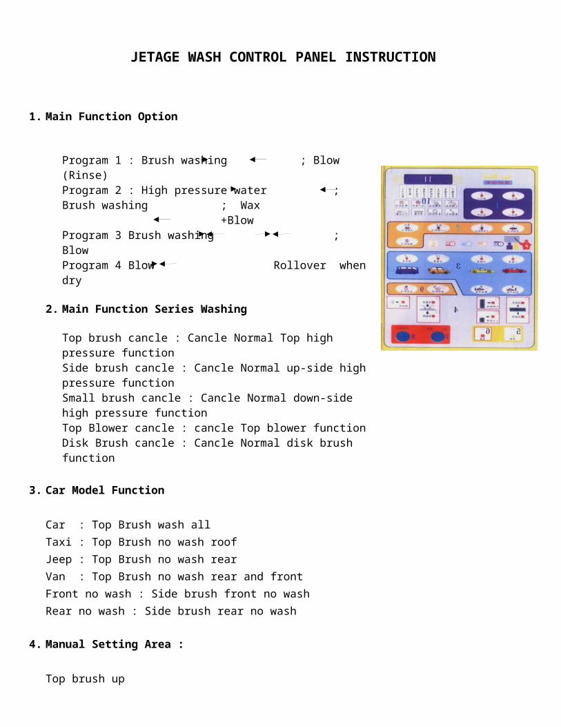
Table of manual model symbol “ d * * * * :Purpose : enter to single element manual checking model. Operation method : Code –d- * * * * Overhaul the way (Restrict the engineer or maintain personnel to use)
1. Top brushes system structure top brush up ( press the button till up , ?
top brush down ( ?
side brush open / close
small vertical brush open / close top brush rotating ( press the button than cancel the Rotating )
Side brush forward rotating ( press the button than cancel )
small vertical brush rotating ( press the button than cancel )
wheel brush forward rotating ( press the button than cancel )
Wheel brush open / close
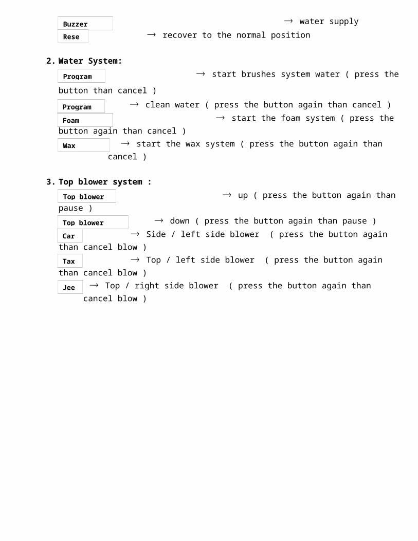
water supply
recover to the normal position
2. Water System:
start brushes system water ( press the button than cancel ) clean water ( press the button again than cancel )
start the foam system ( press the button again than cancel )
start the wax system ( press the button again than cancel )
3. Top blower system :
up ( press the button again than pause )
down ( press the button again than pause )
Side / left side blower ( press the button again than cancel blow )
Top / left side blower ( press the button again than cancel blow )
Top / right side blower ( press the button again than cancel blow )
Top brush up Top brush down
Small vertical brush open
Side brush open
Top brush cancel
Side brush cancel
Small vertical brush cancel
Wheel brush cancel
Wheel brush open
Buzzer cancel
Reset
Program 3
Program 4
Foam cancel
Wax cancel
Top blower up
Top blower down
Car
Taxi
Jeep
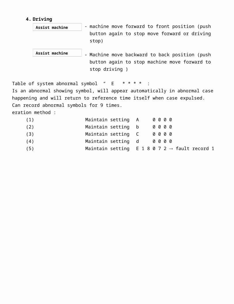
4. Driving - machine move forward to front position (push button again to stop
move forward or driving stop)
- Machine move backward to back position (push button again to stop machine move forward to stop driving )
Table of system abnormal symbol “ E * * * * :Is an abnormal showing symbol, will appear automatically in abnormal case happening and will return to reference time itself when case expulsed. Can record abnormal symbols for 9 times. eration method :
(1) Maintain setting A 0 0 0 0(2) Maintain setting b 0 0 0 0(3) Maintain setting C 0 0 0 0(4) Maintain setting d 0 0 0 0(5) Maintain setting E 1 8 0 7 2 fault record 1
Assist machine forward
Assist machine forward
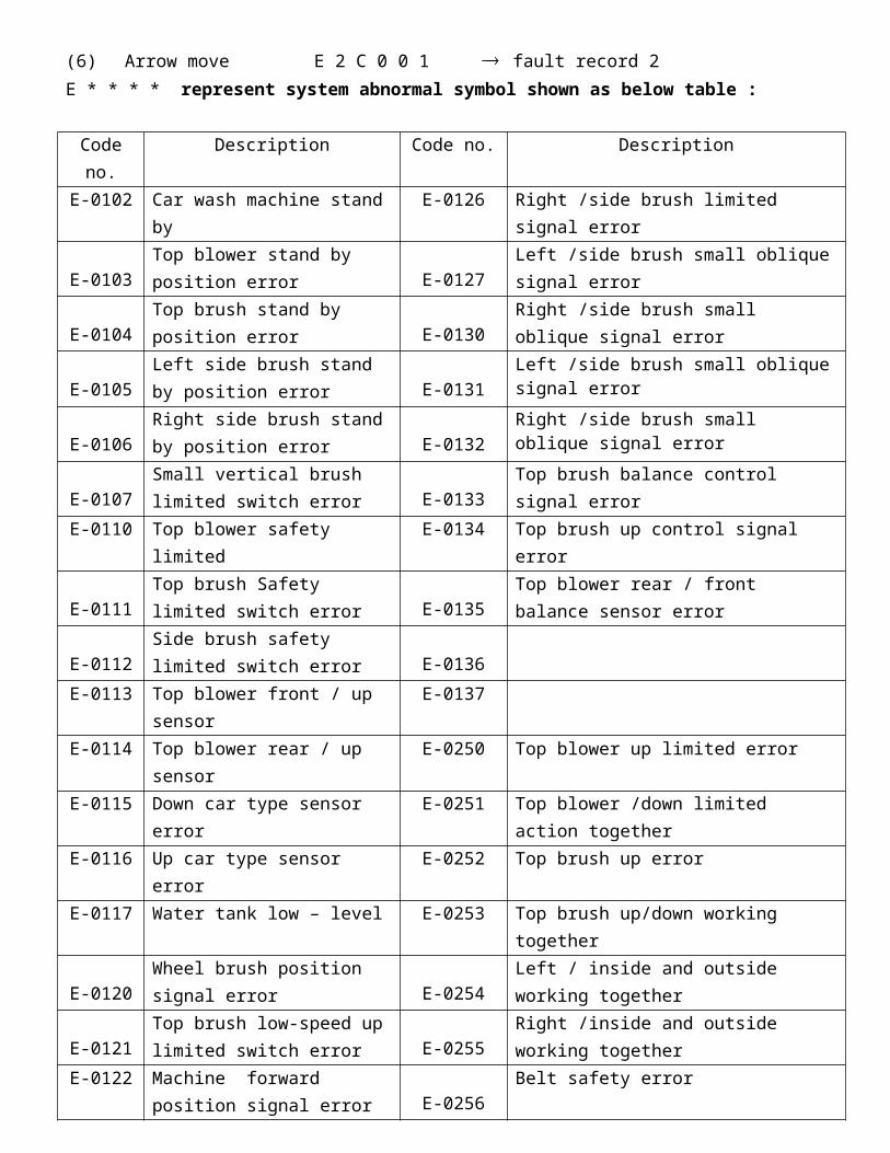
(6) Arrow move E 2 C 0 0 1 fault record 2 E * * * * represent system abnormal symbol shown as below table :
Code no. Description Code no. Description E-0102 Car wash machine stand by E-0126 Right /side brush limited signal error
E-0103Top blower stand by position error
E-0127Left /side brush small oblique signal error
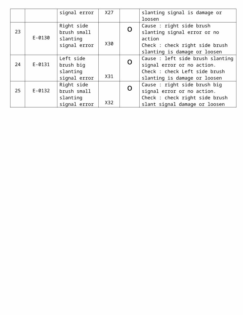
E-0104Top brush stand by position error E-0130
Right /side brush small oblique signal error
E-0105Left side brush stand by position error E-0131
Left /side brush small oblique signal error
E-0106Right side brush stand by position error E-0132
Right /side brush small oblique signal error
E-0107Small vertical brush limited switch error E-0133
Top brush balance control signal error
E-0110 Top blower safety limited E-0134 Top brush up control signal error
E-0111Top brush Safety limited switch error E-0135
Top blower rear / front balance sensor error
E-0112Side brush safety limited switch error E-0136
E-0113 Top blower front / up sensor E-0137E-0114 Top blower rear / up sensor E-0250 Top blower up limited error E-0115 Down car type sensor error E-0251 Top blower /down limited action togetherE-0116 Up car type sensor error E-0252 Top brush up error E-0117 Water tank low – level E-0253 Top brush up/down working together
E-0120Wheel brush position signal error
E-0254Left / inside and outside working together
E-0121Top brush low-speed up limited switch error E-0255
Right /inside and outside working together
E-0122 Machine forward position signal error
E-0256Belt safety error
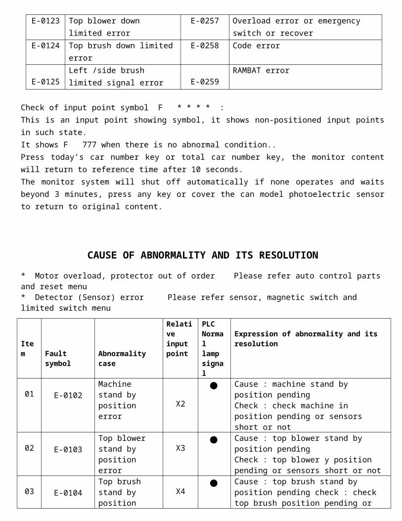
E-0123 Top blower down limited error E-0257 Overload error or emergency switch or recover
E-0124 Top brush down limited error E-0258 Code error
E-0125Left /side brush limited signal error
E-0259 RAMBAT error
Check of input point symbol F * * * * : This is an input point showing symbol, it shows non-positioned input points in such state.It shows F 777 when there is no abnormal condition.. Press today’s car number key or total car number key, the monitor content will return to reference time after 10 seconds. The monitor system will shut off automatically if none operates and waits beyond 3 minutes, press any key or cover the can model photoelectric sensor to return to original content.
CAUSE OF ABNORMALITY AND ITS RESOLUTION
* Motor overload, protector out of order Please refer auto control parts and reset menu* Detector (Sensor) error Please refer sensor, magnetic switch and limited switch menu
Item Fault symbol Abnormality case
Relative input point
PLC Normal lamp signal
Expression of abnormality and its resolution
01 E-0102Machine stand by position error X2 Cause : machine stand by position pending
Check : check machine in position pending or sensors short or not
02 E-0103Top blower stand by position error X3 Cause : top blower stand by position pending
Check : top blower y position pending or sensors short or not
03 E-0104Top brush stand by position error
X4 Cause : top brush stand by position pending check : check top brush position pending or sensor short not
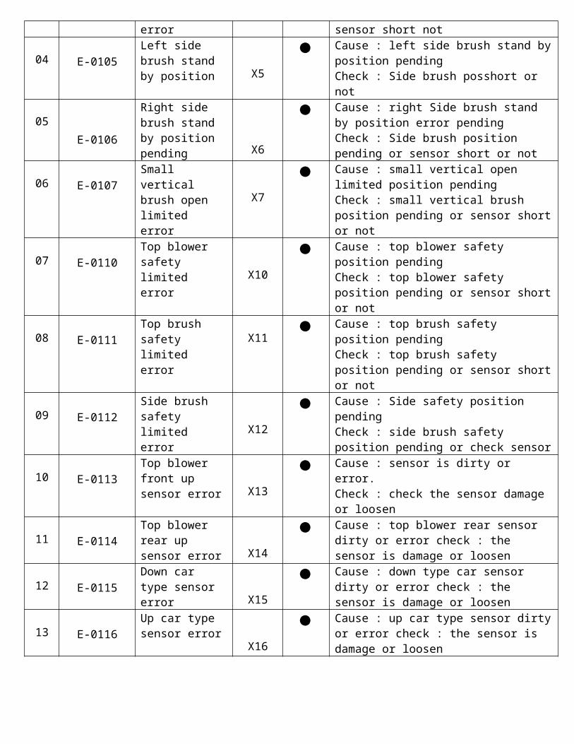
04 E-0105Left side brush stand by position X5 Cause : left side brush stand by position
pending Check : Side brush posshort or not
05 E-0106
Right side brush stand by position pending X6
Cause : right Side brush stand by position error pending Check : Side brush position pending or sensor short or not
06 E-0107Small vertical brush open limited error
X7 Cause : small vertical open limited position pending Check : small vertical brush position pending or sensor short or not
07 E-0110Top blower safety limited error X10 Cause : top blower safety position pending
Check : top blower safety position pending or sensor short or not
08 E-0111Top brush safety limited error X11 Cause : top brush safety position pending
Check : top brush safety position pending or sensor short or not
09 E-0112Side brush safety limited error X12 Cause : Side safety position pending
Check : side brush safety position pending or check sensor
10 E-0113Top blower front up sensor error X13 Cause : sensor is dirty or error.
Check : check the sensor damage or loosen
11 E-0114Top blower rear up sensor error X14 Cause : top blower rear sensor dirty or error
check : the sensor is damage or loosen
12 E-0115Down car type sensor error X15 Cause : down type car sensor dirty or error
check : the sensor is damage or loosen
13 E-0116Up car type sensor error X16 Cause : up car type sensor dirty or error
check : the sensor is damage or loosen

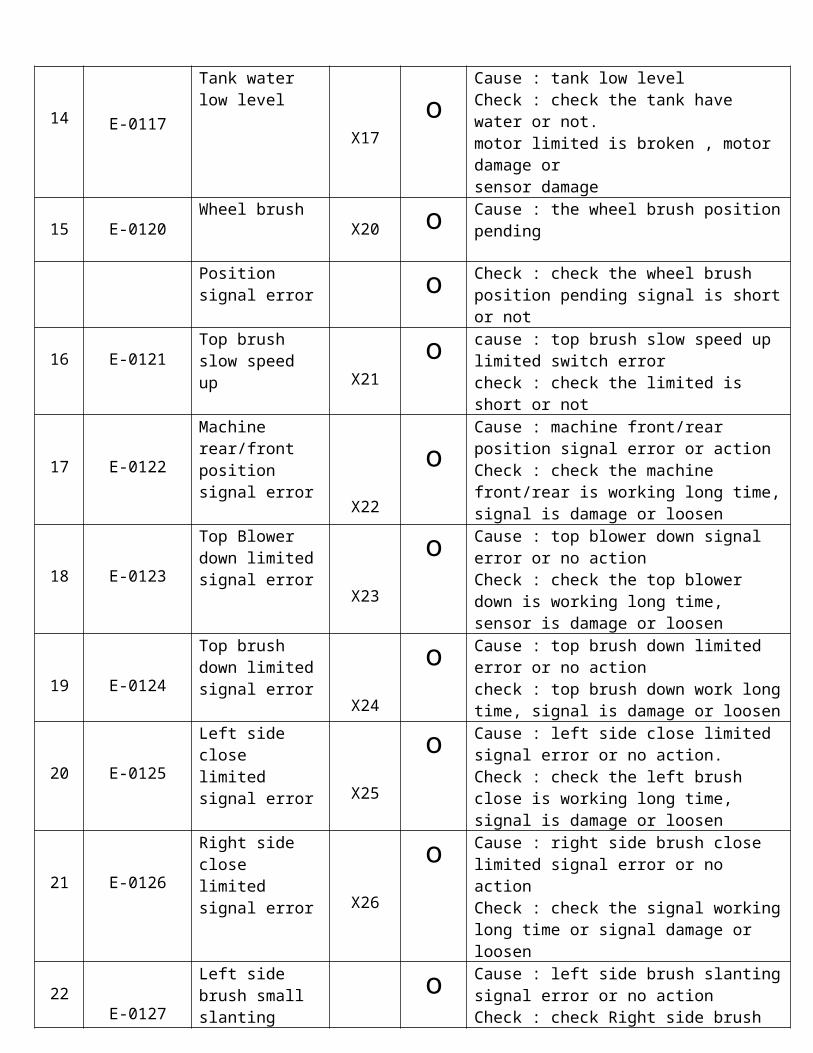
14 E-0117
Tank water low level
X17 οCause : tank low level Check : check the tank have water or not. motor limited is broken , motor damage or sensor damage
15 E-0120Wheel brush
X20 ο Cause : the wheel brush position pending
Position signal error ο Check : check the wheel brush position
pending signal is short or not
16 E-0121Top brush slow speed up X21 ο cause : top brush slow speed up limited
switch error check : check the limited is short or not
17 E-0122
Machine rear/front position signal error
X22ο
Cause : machine front/rear position signal error or action Check : check the machine front/rear is working long time, signal is damage or loosen
18 E-0123
Top Blower down limited signal error
X23ο Cause : top blower down signal error or no
action Check : check the top blower down is working long time, sensor is damage or loosen
19 E-0124
Top brush down limited signal error X24
ο Cause : top brush down limited error or no action check : top brush down work long time, signal is damage or loosen
20 E-0125
Left side close limited signal error X25
ο Cause : left side close limited signal error or no action. Check : check the left brush close is working long time, signal is damage or loosen
21 E-0126
Right side close limited signal error X26
ο Cause : right side brush close limited signal error or no action Check : check the signal working long time or signal damage or loosen
22 E-0127
Left side brush small slanting signal error X27
ο Cause : left side brush slanting signal error or no action Check : check Right side brush slanting signal is damage or loosen
23 E-0130Right side brush small slanting signal error X30
ο Cause : right side brush slanting signal error or no action Check : check right side brush slanting is damage or loosen
24 E-0131Left side brush big slanting signal error X31
ο Cause : left side brush slanting signal error or no action. Check : check Left side brush slanting is damage or loosen
25 E-0132
Right side brush small slanting signal error X32
ο Cause : right side brush big signal error or no action. Check : check right side brush slant signal damage or loosen
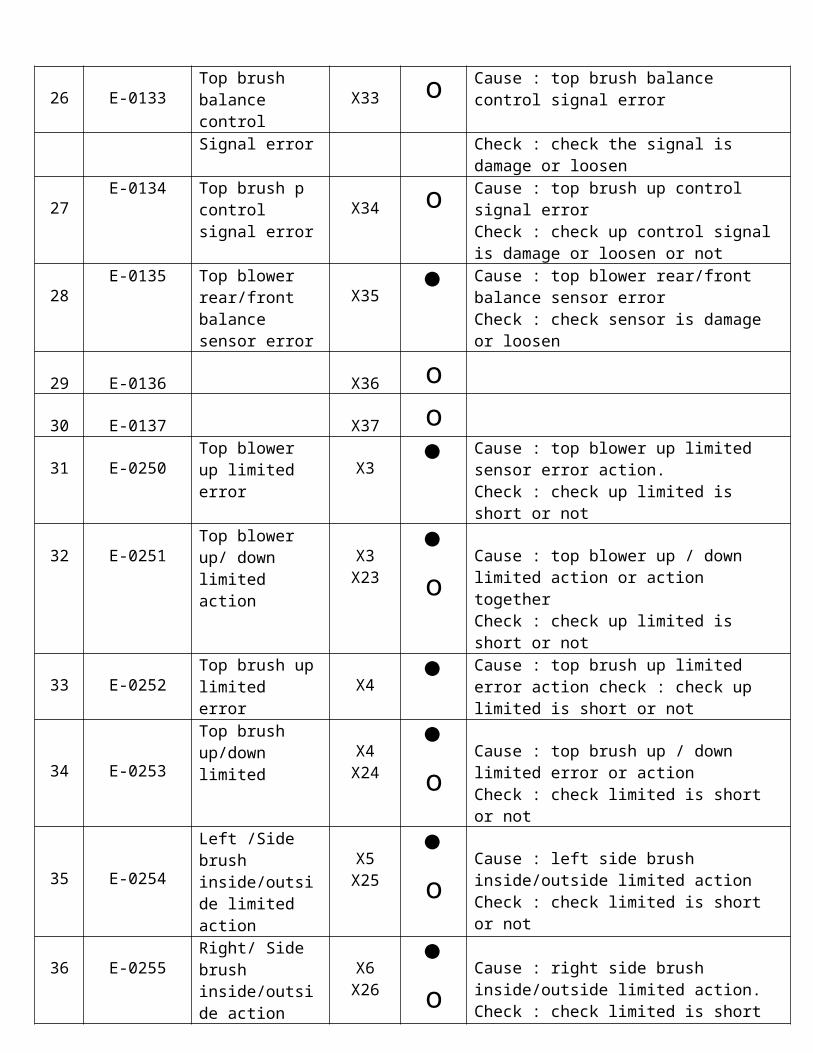
26 E-0133Top brush balance control
X33 ο Cause : top brush balance control signal error
Signal error Check : check the signal is damage or loosen
27E-0134 Top brush p
control signal error
X34 ο Cause : top brush up control signal error Check : check up control signal is damage or loosen or not
28E-0135 Top blower
rear/front balance sensor error
X35 Cause : top blower rear/front balance sensor error Check : check sensor is damage or loosen
29 E-0136X36 ο
30 E-0137X37 ο
31 E-0250Top blower up limited error
X3 Cause : top blower up limited sensor error action. Check : check up limited is short or not
32 E-0251Top blower up/ down limited action
X3X23
ο
Cause : top blower up / down limited action or action together Check : check up limited is short or not
33 E-0252Top brush up limited error
X4 Cause : top brush up limited error action check : check up limited is short or not
34 E-0253
Top brush up/down limited
X4 X24
ο
Cause : top brush up / down limited error or action Check : check limited is short or not
35 E-0254
Left /Side brush inside/outside limited action
X5X25
ο
Cause : left side brush inside/outside limited action Check : check limited is short or not
36 E-0255Right/ Side brush inside/outside action
X6X26
ο
Cause : right side brush inside/outside limited action.Check : check limited is short or not
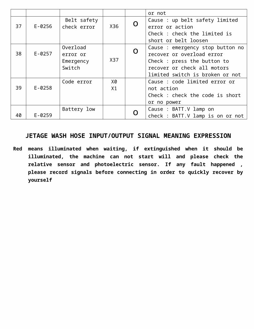
37 E-0256 Belt safety check error
X36 ο Cause : up belt safety limited error or action Check : check the limited is short or belt loosen
38 E-0257Overload error or Emergency Switch
X37 ο Cause : emergency stop button no recover or overload error Check : press the button to recover or check all motors limited switch is broken or not
39 E-0258Code error X0
X1Cause : code limited error or not action Check : check the code is short or no power
40 E-0259Battery low ο Cause : BATT.V lamp on
check : BATT.V lamp is on or not
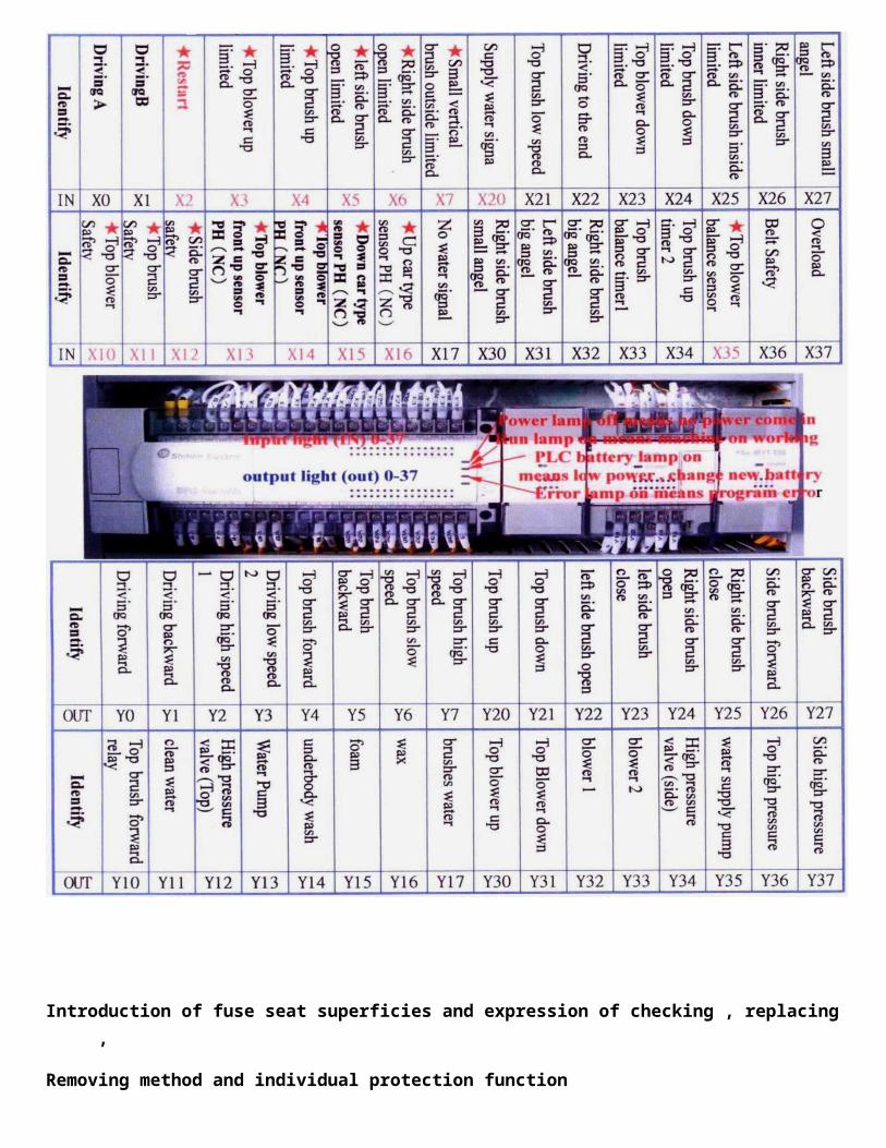
JETAGE WASH HOSE INPUT/OUTPUT SIGNAL MEANING EXPRESSION
Red means illuminated when waiting, if extinguished when it should be illuminated, the machine can not start will and please check the relative sensor and photoelectric sensor. If any fault happened , please record signals before connecting in order to quickly recover by yourself
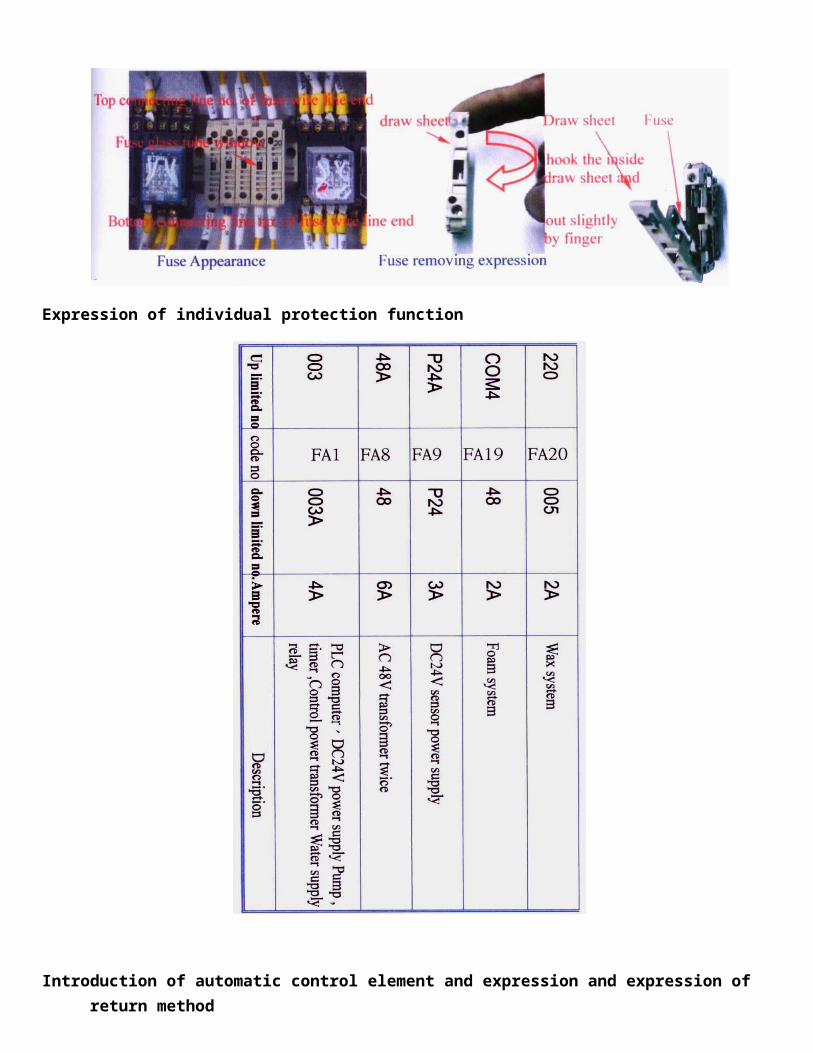
Introduction of fuse seat superficies and expression of checking , replacing ,
Removing method and individual protection function
Expression of individual protection function
Introduction of automatic control element and expression and expression of return method
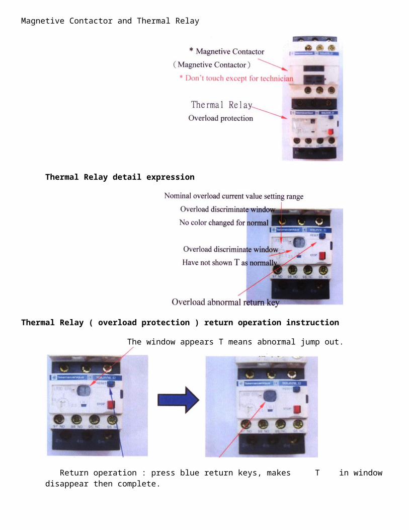
Magnetive Contactor and Thermal Relay
Thermal Relay detail expression
Thermal Relay ( overload protection ) return operation instruction
The window appears T means abnormal jump out.
Return operation : press blue return keys, makes T in window disappear then complete.
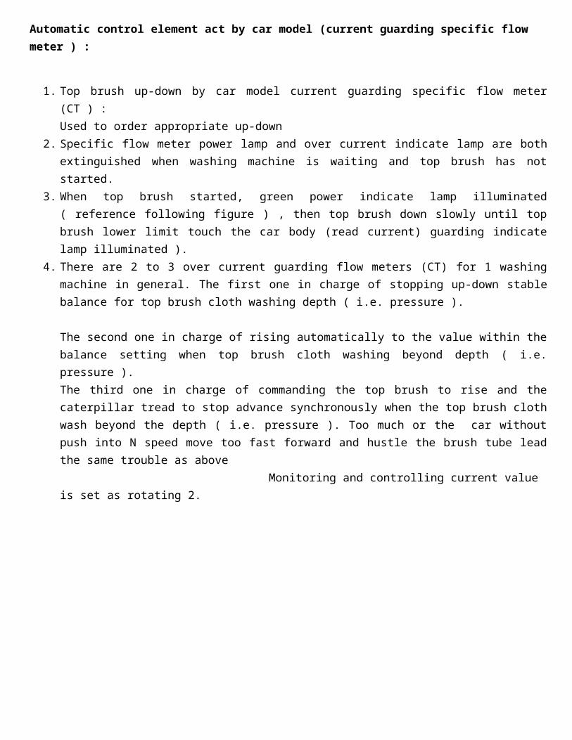
Automatic control element act by car model (current guarding specific flow meter ) :
1. Top brush up-down by car model current guarding specific flow meter (CT ) : Used to order appropriate up-down
2. Specific flow meter power lamp and over current indicate lamp are both extinguished when washing machine is waiting and top brush has not started.
3. When top brush started, green power indicate lamp illuminated ( reference following figure ) , then top brush down slowly until top brush lower limit touch the car body (read current) guarding indicate lamp illuminated ).
4. There are 2 to 3 over current guarding flow meters (CT) for 1 washing machine in general. The first one in charge of stopping up-down stable balance for top brush cloth washing depth ( i.e. pressure ).
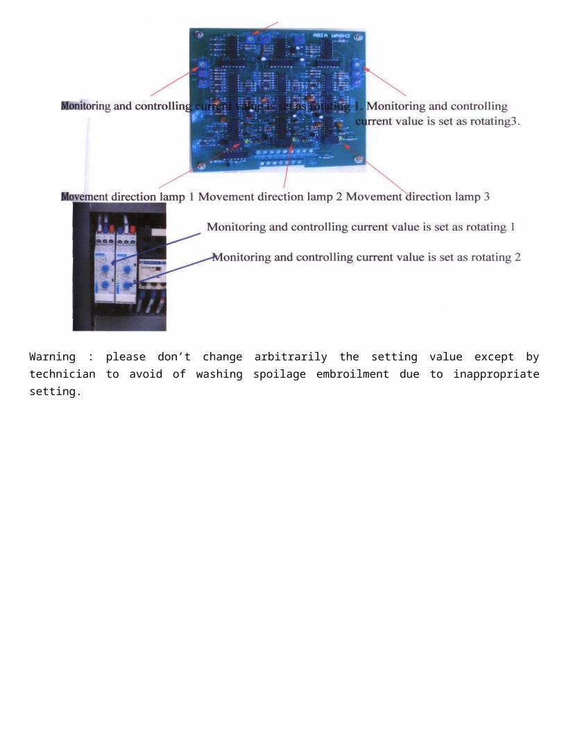
The second one in charge of rising automatically to the value within the balance setting when top brush cloth washing beyond depth ( i.e. pressure ).The third one in charge of commanding the top brush to rise and the caterpillar tread to stop advance synchronously when the top brush cloth wash beyond the depth ( i.e. pressure ). Too much or the car without push into N speed move too fast forward and hustle the brush tube lead the same trouble as above Monitoring and controlling current value is set as rotating 2.
Warning : please don’t change arbitrarily the setting value except by technician to avoid of washing spoilage embroilment due to inappropriate setting.
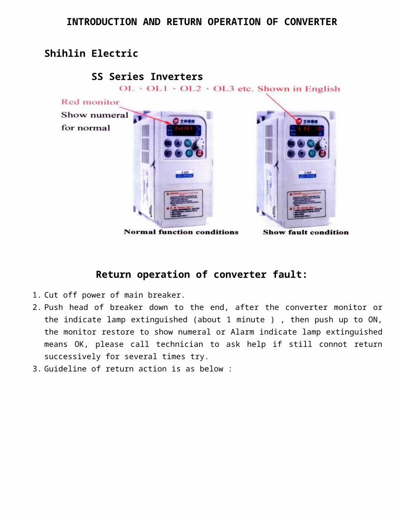
INTRODUCTION AND RETURN OPERATION OF CONVERTER
Shihlin Electric SS Series Inverters
Return operation of converter fault:
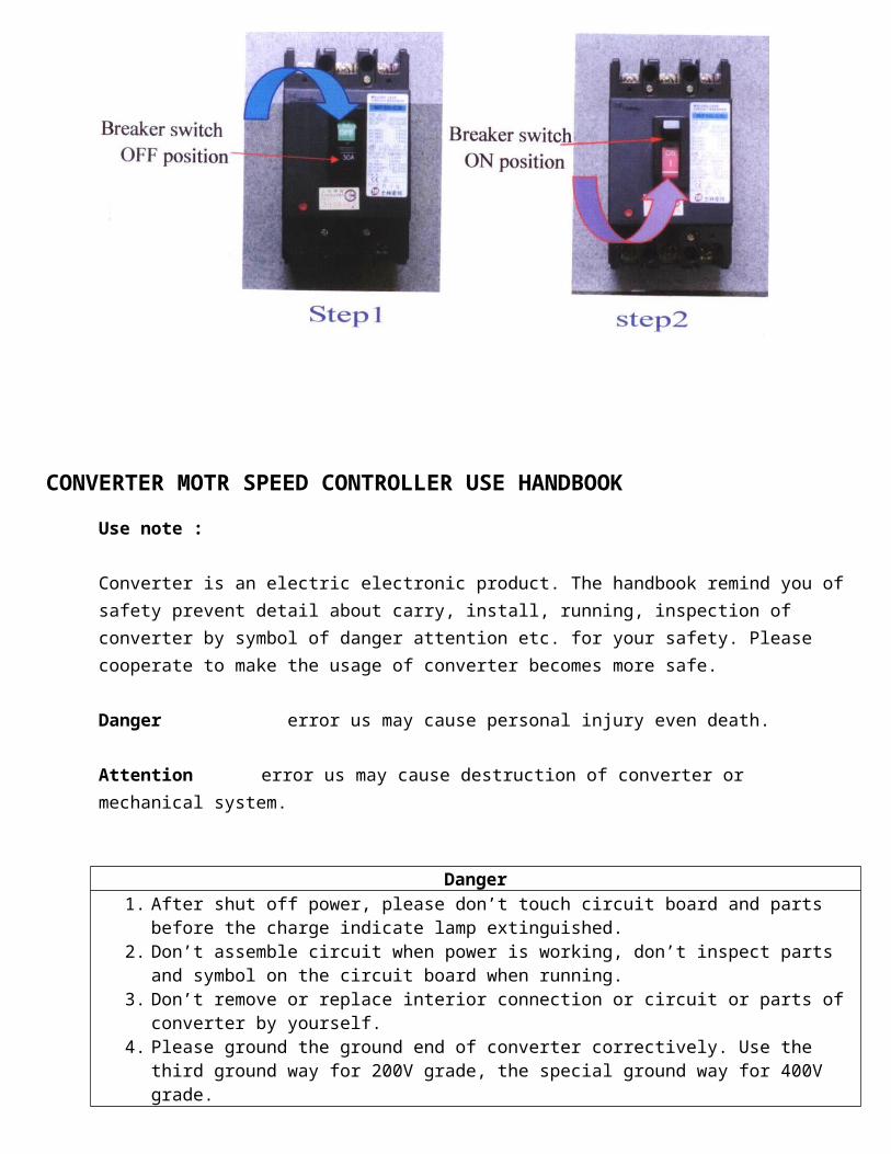
1. Cut off power of main breaker. 2. Push head of breaker down to the end, after the converter monitor or the indicate lamp extinguished
(about 1 minute ) , then push up to ON, the monitor restore to show numeral or Alarm indicate lamp extinguished means OK, please call technician to ask help if still connot return successively for several times try.
3. Guideline of return action is as below :
CONVERTER MOTR SPEED CONTROLLER USE HANDBOOK
Use note :
Converter is an electric electronic product. The handbook remind you of safety prevent detail about carry, install, running, inspection of converter by symbol of danger attention etc. for your safety. Please cooperate to make the usage of converter becomes more safe.
Danger error us may cause personal injury even death.
Attention error us may cause destruction of converter or mechanical system.
Danger 1. After shut off power, please don’t touch circuit board and parts before the charge indicate
lamp extinguished. 2. Don’t assemble circuit when power is working, don’t inspect parts and symbol on the circuit
board when running. 3. Don’t remove or replace interior connection or circuit or parts of converter by yourself. 4. Please ground the ground end of converter correctively. Use the third ground way for 200V
grade, the special ground way for 400V grade.
Attention1. Please don’t proceed pressure endurance test to the interior parts of converter, these semi-
conductor parts are easy to destroy by high pressure. 2. Don’ absolutely connect the output end T1(U) , T2(V) , T3(W) of converter to AC power. 3. The main circuit boards CMOS IC of converter is easy to be influenced and destroyed by static
electricity please don’t touch main circuit board.
Safety note detail :
Note details when use :
1. Before power working :
Attention
(1) The power voltage used must be the same as input voltage specification of converter. (2) There is a connector inside the converter of machine models above 15HP to provide power
selection for interior converter, please chose the same voltage as the power voltage before use. (3) Please don’t raise the front cover when carry converter, it’s better to hold the radiator of
converter to avoid of person injury and converter damage come from converter falling out. (4) Please install the converter on incombustible material like metal. Please don’t install on or near
combustible material to avoid of fire. (5) If there are many converters put in a control panel, please add a radiator fan to drop temperature
in box down below 40°C to avoid of overheated or fired. (6) Please shut off power before remove or install operating tool, and fix the tool in according to the
figure to avoid of inappropriate touching makes the tool fault or loss to show.
1. Danger
When distribute the main circuit end line, identify correctly that L1 , L2 , L3 is the power input end, but no T1 , T2 , T3 , or it will make converter destroyed when power work.
2. Power working Danger Don’t insert or draw out the connector of converter when power working to prevent the control board damaged by impulse flushing.
3. Before running :
Danger Please identify the used power voltage is same as the capacity of used machine model is same as the capacity set by converter Fn00.
Attention Please identify the used power voltage is same as it set by Fn30, or the converter will make error action. ( note ) The power voltage value set by Fn30 will twinkle on converter for 5 seconds when power working, if it is different from present voltage value, modify Fn30 immediately until it is same as the present voltage value.
4. Running :
Danger (1) Don’t engage in or cut off the motor series running, or it will makes converter over current jump out or
its main circuit burned out. (2) Please don’t take front cover of converter out when power working, prevent prevent person from
electric shock injury. (3) The motor will restart automatically after stop running when the restart function is set, please don’t
close to machine to prevent from danger. (4) The stop function can worked only when it is set, it is different from the usage of emergency button,
please ware to use.
Attention (1) Don’t touch element generate heat like radiator seat, brake resistance, etc..(2) Converter can run easily from low speed to high speed, please identify the tolerance range of motor and
machine. (3) Please attention to the relative setting of usage when use the brake. (4) Please don’t check the symbol on circuit board when converter running. (5) All converters are adjusted OK when complete, please don’t change it arbitrary. (6) Please identify that power has cut off and charge indicate lamp ( LED101 ) has extinguished before
remove or maintain.
5. Maintaining :
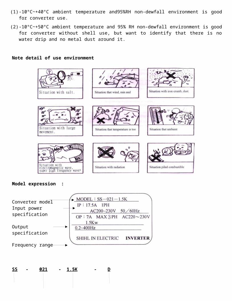
Attention (1) -10°C~+40°C ambient temperature and95%RH non-dewfall environment is good for converter use.
(2) -10°C~+50°C ambient temperature and 95% RH non-dewfall environment is good for converter without shell use, but want to identify that there is no water drip and no metal dust around it.
Note detail of use environment
Model expression :
Converter model Input power specification
Output specification
Frequency range
SS - 021 - 1.5K - D
Series appearance : 1 , no: standard model 2 , D: AppropriationPower voltage : Apply electrical engineering electric capacity
021 : 220V 1-PHASE 023 : 220V 3-PHASE043 : 440V 3-PHASE
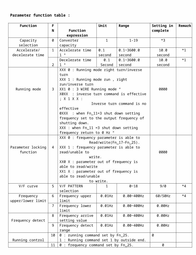
Parameter function table :
Function FN Function expression
Unit Range Setting in complete
Remark
Capacity selection 0 Converter capacity 1 1-19 *3Accelerate/decelerate
time 1 Accelerate time 1 ° 0.1 second 0.1~3600.0 second 10.0 second *1
2Decelerate time 1 ° 0.1
Second0.1~3600.0 second 10.0 second *1
Running mode 3
XXX 0 : Running mode right turn/inverse turn XXX 1 : Running mode run , right run/inverse turn XX1 0 : 3 WIRE Running mode °X0XX : inverse turn command is effective ; X 1 X X : Inverse turn command is no effective 0XXX : when Fn_11=3 shut down setting frequency set to the output frequency of shutting down. XXX : when Fn_11 =3 shut down setting frequency return to 0 Hz °
0000
Parameter locking function
4
XXX 0 : frequency parameter is able to Read/write(Fn_17-Fn_25).XXX 1 : frequency parameter is able to read/unable to write.XX0 X : parameter out of frequency is able to read/writeXX1 X : parameter out of frequency is able to read/unable to write.
0000
V/F curve 5 V/F PATTERN selection 1 0~18 9/0 *4
Frequency upper/lower limit
6 Frequency upper limit 0.01Hz 0.00~400Hz 60/50Hz *47 Frequency lower limit 0.01Hz 0.00~400Hz 0.00Hz
Frequency detect 8 Frequency arrive
setting value 0.01Hz 0.00~400Hz 0.00Hz
9 Frequency detect range 0.01Hz 0.00~400Hz 0.00Hz
Running control 10 0 : running command set by Fn_25. 1 : Running command set 1 by outside end.
0
Frequency control
11 0 : frequency command set by Fn_25. 1 : command set by VR on Keypad. 2 : command set by VR on TM2or analogy symbol. 3 : command set by UP/DOWN end on TM2.
0
Stall prevention
12 XXX 0 : stall prevention is effective when acceleration. XXX 1 : stall prevention is on effective when acceleration. XX 0X : stall prevention is effective when deceleration.XX1X : stall prevention is on effective when deceleration.X 0XX : stall prevention is effective when running .X1XX : stall prevention is no effective when running. 0 XXX : deceleration time of stall prevention is Fn_02 when running. 1 XXX : deceleration time of stall prevention is Fn_15 when running.
13 Start point of stall Prevention when Acceleration.
1% 30-200%110%
DAILY INSPECTION AND ROUTINE INSPECTION Converter must proceed daily and routine maintain inspection to keep inspection to keep more safe and more stable running. The items list below must be check to keep converter run more safe and more stable. Until the “charge” indicate lamp of converter has extinguished for 5 minutes, then start to check to prevent maintain worker from injury by remain electric of capacitor of converter.
Inspection item
Inspection content Inspection period Inspection
methodJudge criterion Counterplot for
abnormal Daily Year
Ambient Environment Of used Machine
Please identify ambient Temperature, humidity.
0
Measured with thermometer, weather glass in according to install note detail.
Temperature-10~40°CHumidity below 95%RH
Improve local Environment
Whether piled combustible Material. 0
By sight No anything abnormal
Converter install and ground
Whether machine appear abnormal vibration. 0
By sight by audition
No anything abnormal
Lock tightly the install screw
Whether ground resistance value meet regulation.
0Check resistance by multi-use electric meter.
200V grade for 100Ω below 400V grade for 10 Ω
Interior fix screw of exterior end of converter.
Whether lock part is loosen or shake. 0
Check whether the screw loosen by sight or by roller bar.
No abnormal case Lock or send to repair Whether the end plate is
damaged. 0
Connect line inside converter
Whether it deformed, tilted. 0 By sight No abnormal case Replace or send to
repair Whether wire cloth is broken 0
Radiator sheet Whether any dust or crumb piled.
0 By sight No abnormal caseClean accumulation like dust
Print circuit board
Whether any conductible metal or oil piled. 0
By sight No abnormal case
Clean or replace circuit board
Whether the parts discolored, overheated, overheated, carbonized black.
0
Cooler fan
Whether any abnormal vibration or abnormal sound appeared.
0By sight by audition
No abnormal case Replace the cooler fan
Whether dust or crumb pile. 0
By sight No abnormal case Clean
Power element Whether any dust or crumb piled. 0
By sight No abnormal case Clean
Check resistance value among every end 0
Measured by multi-use electric meter.
No short, no break for 3 phase output.
Replace power element or converter.
Capacitor Whether any malodor or leakage appeared. 0 By sight No abnormal case
Replace capacitor or converter.
Whether any swell or extrusion appeared. 0
RECIPROCATING PISTON PUMP OPERATION HANDBOOK
( include water knife washing machine and handheld handgun pump )
Using note : this mode of pump can only be used in clean pure water or general water/cleanser water, please connect our technique department or local agent before use corrosive additive like acid solvent. The pump enable to endure 75°C water, please connect out technique department or local agent if you want to treat higher temperature water.
Installation : Work will be easy if you install by step, correct installation ensure perfect performance and long life of pump.
Collect water pipe series : Be aware to never accumulate air within it when install collect water pipe series, and ensure all joints are sealed well to prevent pump from sinking air at the same time. All joints with thread must covered by P.T.F.E tape to keep air sealed. Inner diameter of collect water pipe must be equal to or greater to that of collect joint of pump. We suggest installing a filter mesh in pipe to prevent something abnormal from intruding into pump. **maximum neglect pressure 0.3bar(the highest temperature 24°C) maximum positive pressure 8bar °
Carry water pipe : Be ware inner diameter of water pipe must be equal to that of outlet pipe of pump at least to avoid the pressure within pipe to over loss. Operation pressure must not be higher over 10% than nominal maximum pressure of pump.
Start process : If the pump is driven by slid roller series, check whether series run well to prevent belt from any damage and consume. Don’t absolutely make the pump dry run over some seconds. Check whether the filter mesh is clean before start pump. Open all exhaust valves to discharge all air and help the pump run to the fastest.
Lubrication : Check the oil level usually. Replace lubricant after 50 hours or 220 car time for first operation, then replace once every 500 hours or 20000 car time. Please use lubricants list in next page.
Boot process : Wipe the pump clean once after a period of time in ideal condition. Please sink pure water by pump for 1 minute to clean out the cleanser when add cleanser, then run the pump for 20 seconds without supplying water to void it. It becomes more important for frosting in cold weather condition.
RECIPROCATING PISTON PUMP TROUBLE SHOOTING
Pump run normally when install, but pressure too low.
1. Pump sink air inside. 2. Air valve adhered. 3. Inverse pressure valve series
fault.4. Nozzle specification error. 5. Piston rings worn out.
1. Check pure water supplying and possibility of air intrusion.
2. Check, clean and replace for necessary. 3. Check, clean and replace for necessary.4. Check, clean and replace for necessary.5. Check, clean and replace for necessary.
Pressure is unstable 1. Air valve damage. 2. Air valve chocked. 3. Pump sink air inside. 4. Piston ring worn out.
1. Check and replace for necessary. 2. Check and clean for necessary. 3. Check pure water supplying and
possibility of air intrusion in collect water pipe joint.
4. Check and replace for necessary.
Used normally for a period of time, then pressure drop down.
1. Nozzle worn out.2. Collect water or carry water
valve worn out. 3. Collect water or carry water
valve chocked. 4. Inverse pressure valve series
error or worn out. 5. Piston rings worn out.
1. Check and replace for necessary.2. Check and replace for necessary .3. Check and clean for necessary .4. Check and replace for necessary .5. Check and replace for necessary .
Pump noise
1. Any air inside collect water pump.
2. Collect water or carry water valve tongue is damage or fatigue.
3. There is something abnormal inside air valve.
4. Bearing is damage. 5. Water temperature is too high.
1. Check pure water supplying and extrude air inside collect water pump.
2. Check and replace for necessary.3. Check and clean for necessary.4. Check and replace for necessary.5. Drop water temperature down below
75°C
Oil include water 1. Oil seal is damage.2. Air humidity is too high. 3. Piston rings worn out.
1. Check and replace for necessary.2. Check and replace for oil more frequent.3. Check and replace for necessary.
Lower pump drip water. 1. Piston rings worn out.2. O.R. Piston protection rings
worn out.
1. Check and replace for necessary.2. Check and replace for necessary.
Oil leakage 1. Oil seal is damage. 1. Check and clean for necessary.Carry water pipe vibration is too large.
1. Pressure of pressure reservoir is too low.
2. Air valve run irregularly.
1. Check and clean for necessary.2. Check and replace for necessary.
Appropriate lubricant table
CHINA PETROLUM CO., LTD. >>>2 0 W 5 0 IP >>> UALGRADE CASTROL >>> HD MACH(BP) >>> NERGOL HD ESSO >>> EXTRA MOTORS OIL MOBILE >>> HD FINA >>> VS SHELL >>> SUER PLUS FINA >>> DELTA PLUS M.O. TOTAL >>> SUPER HD TEXACO >>> HAVOLINE M.O. GULF >>> UNIG
Ambient temperature-10°C to 30°C viscosity SAE 20W-30W
The pump ( R series ) uses the precautions
Checking and changing cycle of first, lubricating oil : 1. Check at ordinary times:
(1) Check the total amount of the lubricating oilMust guarantee that the total amount of the Lubricating oil is between cheering upper limit “ H “and lower limit “ L “ of the range on (must use the same kind of lubricating oil while Supplementing the lubricating oil ).
(2) Check whether the lubricating oil has gone bad, need to all change when the lubricating oil has a large amount of impurity or present the phenomenon of melting in vain.
2. The changing of lubrication oil : (1) Change time to change in order to use for three months for the first time or after using for 300 hours
for the first time; Later used six months later or used and changed again 600 hours later each time. (2) The lubricating oil used must be equivalent to the motor lubricating oil of ISO VG100 grade or the ISO
VG150 grade, the adding amount of lubricating oil of its all series is as follows: R—2 series-----0 . 5 liters R—3 series-----0 . 4 liters
R—5 series-----0 . 55 liters R—7 series-----1 . 1 liters
Characteristic that the high-pressure pump dallies : 1. When there is a frozen situation to ice the air coldly, but Jing competent to remove movement of
moisture in the pump for prevent from icy and unable to work, dally and control it within one minute. 2. Getting rid of water need consider above-mentioned situations too when working in Jing competent
drain pipe.
After is worthy of in charge of using the precaution in choice of the requirements : 1. Whether water requirements in charge of worthy of choose listed as follows.
(1) The above that R-208 , R-311T , R-511 , R-270 type are ¾ : (inch). (2) The above that R-713 type is 1 “ (inch).(3) In order to suck the cleaner while setting up the switch in the feed pipe, it is apt to cause the
performance of the pump to reduce, it is apt to become the reason to break down. (4) When too drain off water and is worthy of being in charge of long , careful , will produce pressure
losses, according to have specification the whole quantity Chang , load of valve drain off water , will cause the rising of the pump.
Direction of rotating of the pump : 1. For the need that is lubricated in the crankcase, the direction of rotation that please keep the pump
certain (arrow point direction). 2. If the lubricating oil is put too much, when the reverse direction is rotated, the lubricating oil will
overflow.
Reducer selection and maintain regular
Lubricant selection : Lubricant with appropriate viscosity can make worm and gear steering slide easily, and reducer develop fully its characteristic in high load and impulse load. It’s the selection table of reducer lubricant :
Load Ambient temperature
ISO SHELL MOBIL INDIAN PETROLUM
ESSO ARAL
N o r m a ll o a d
-20°C~10°C HD-150 Omala oil R150
Mobil gear629
CPC E.P lubricant HD-150
Spartan EP-220
Degol BG-220
10°C~40°C HD-320 Omala oil R320
Mobil gear632
CPC E.P lubricant HD-320
Spartan EP-320
Degol BG-320
40°C~65°C HD-460 Omala oil R460
Mobil gear634
CPC E.P lubricant HD-460
Spartan EP-460
Degol BG-460
S u p e r l o a d
-20°C~10°C HD-320 Omala oil R320
Mobil gear632
CPC E.P lubricant HD-320
Spartan EP-320
Degol BG-320
10°C~40°C HD-460 Omala oil R460
Mobil gear634
CPC E.P lubricant HD-460
Spartan EP-460
Degol BG-460
20°C~10°C HD-680 Omala oil R680
Mobil gear636
CPC E.P lubricant HD-480
Spartan EP-680
Degol BG-680
Maintain regular : Replace oil after 300 hours for the first use, then replace per 2500 hours. ( note ) : Please connect manufacturer before used in high speed, high temperature, low speed, high load, enforce lubrication, etc. special cases.
Maintain note of bearing
The bearings need to inject lubricant routinely to ensure its steel ball rolling normally.
1. Operation rule of bearing injecting lubricant :
2. Replace and maintain period of bearing lubricant for various work environment and temperature :
Work environment condition
Work temperature Maintain periodDn:5000mm below Dn:5000mm above
Clean
50° below Fill it when is insufficient 1 . 5 ~ 3 years50° above 70° below 1 ~ 2 year 6 ~ 1 2months 70° above 100° below 4 ~ 8 months 1 ~ 3 months100° above 2 ~ 4 weeks 1 ~ 2 weeks
Thin dust 50° below 1 ~ 2 years 6 ~ 1 2 months50° above 70° below 4 ~ 8 months 2 ~ 4 months70° above 100° below 3 ~ 6 weeks 2 ~ 4 weeks100° above 1 ~ 2 weeks Every week
Thick dust 50° above 70° below 1 ~ 2 months 3 ~ 6 weeks70° above 100° below 2 ~ 4 weeks 1 ~ 2 weeks100° above 1 ~ 7 days 1 ~ 3 days
Very wet and flowage place 1 ~ 3 days Every days
PS : dn=axis diameter * rotate speed
The bearing disposes, lubricates the time based maintenance of the position to prove
Exit motor driving chain, top high pressure spray washing up-down driving chain, top high pressure spray washing move driving chain, move lateral brush transmission axis driving chain all need to apply grease appropriately to ensure to run stably and to increase its life.
Introduction and using rule of photoelectric, electromagnetic sensor and limiter.
1. Introduction of photoelectric sensor :
2. Introduction of electromagnetic sensor and limiter :
3. Electromagnetic sensor using note detail :
4. Installation and using rule of photoelectric sensor : (1) The photoelectric switch used for a period of time will occur induce distance decay due to
photoelectric sensor lens polluted by environment. Please wipe lens by wet cloth first, then by dry cloth until it is clean. Don’t use any acid alkali cleanser to avoid of corrosion or damage of photoelectric sensor.
(2) Forbid seriously use the sensor in place with organic dissolvent. (3) Don’t expose the photoelectric switch in dust, water steam, or will affect its running.(4) Don’t irradiate strong light ( like sunlight ) into range within angle of incidence of sensor ( especially
for light receiver ) , and be ware to avoid of reflection near lens body and background surface. (5) The operation voltage and load current provided by photoelectric switch can’t beyond the maximum
range indicated by handbook.
Installation and Description of Sensors
Upper and lower car type photo sensor
When the cars are located at normal position ( with limit on ), the signal can be sent to the computer. Such signal shall be treated as standby type, otherwise the Car Washer cannot be activated. It is imperative to check if the sensor or sensor position is correct.
Travel encoding (travel distance) sensor :(1) During the forward and backward movement of Car Washer, the Travel Encoding Sensor shall match
with the upper, middle and lower car-type sensors so as to register the distance referential value for carrying out each car washing process appropriately and to achieve safe and clean car washing effect.
(2) When the Car Washer moves, the sensor action indicator flickers alternately. (3) In the indicator fails to flicker, maybe the sensor securing position is not appropriate ( too far away
from the sensing plate ) and it should be adjusted. If the sensor still fails to act normally, then it could be replaced with a new one.

Top brush slow lifting sensor and top brush safety sensor: (1) Brush slow sensor :
When the middle part of engine plate enters the windshield during the top brush washing, the unit slows down the rotating speed so as to pass the front brush safely and avoid hooking the old, fragile, renovated or lifted brush. By adjusting the position of sensor, a clean and safe car washing process can be executed appropriately.
(2) Top brush safety sensor: During the top brush washing process, the washing effect can be assured by the independent-control sensor going up and down along with the car type in conjunction with the slow ascending sensor of the top brush. With the top brush safety sensor, the safety guard can be provided in case of the aforesaid problem. After being triggered due to excessive washing pressure, the Car Washer stops moving for the top brush to detach from the over –weighted car body to achieve the safety protection effect. Top brush lifting belt safety inspection:
Such inspection set required to prevent the slackened belt from detaching the belt reel in such a way that the belt is cut in two by the belt reel and causes the falling of the top brush holder.
Lateral brush major/minor inclination angle sensor: (1) Lateral brush minor inclination sensor (lateral brush balance function):
During washing both sides of the car, the brush tends to incline when the tube closes and gets near the car body. Upon activating, the minor inclination will prevent the tube from closing and appropriately adjust the distance between the sensor and the sensing plate according to the required car washing pressure.
(2) Lateral brush major inclination sensor: During washing both sides of the car, the bush tends to incline when the tube closes and gets near car body. In the event such angle becomes so big as to press the car body, the unit will command the lateral brush to open to appropriate angle (lateral brush minor inclination).
Lateral brush safety instructions : If the lateral brush cannot be smoothly opened during washing the front and the rear part of the car in such a way that the lateral brush holder is excessively inclined because the lateral brush gets stuck on the car body, the system will stop the Car Washing from moving in time and before jeopardizing the car body so as to avoid the damage.