Embed Size (px)
Citation preview

UNIT III
INFRASTRUCTURE AS A SERVICE (IAAS) & PLATFORM AND SOFTWARE AS A SERVICE (PAAS / SAAS)
3.1 Virtual Machines Provisioning and Migration Services3.1.1 Introduction and Inspiration
Cloud computing is an emerging research infrastructure that builds on the achievements of different research areas, such as service-oriented architecture (SOA), grid computing, and virtualization technology. 3.1.2 Background and Related Work
In this section, we will have a quick look at previous work, give an overview about virtualization technology, public cloud, private cloud, standardization efforts, high availability through the migration, and provisioning of virtual machines, and shed some lights on distributed management’s tools.3.1.2.1 Virtualization Technology Overview
Virtualization can be defined as the abstraction of the four computing resources (storage, processing power, memory, and network or I/O). It is conceptually similar to emulation, where a system pretends to be another system, whereas virtualization is a system pretending to be two or more of the same system .Virtual machine’s technology makes it very flexible and easy to manage resources in cloud computing environments, because they improve the utilization of such resources by multiplexing many virtual machines on one physical host. These machines can be scaled up and down on demand with a high level of resources’ abstraction. Virtualization enables high, reliable, and agile deployment mechanisms and management of services, providing on-demand cloning and live migration services which improve reliability.
3.1.2.2 Public Cloud and Infrastructure ServicesThere are many examples for vendors who publicly provide infrastructure as a service.
Amazon Elastic Compute Cloud (EC2), but the market now bristles with lots of competition like GoGrid, Joyent Accelerator, Rackspace, AppNexus, FlexiScale, and Manjrasoft Aneka.

Amazon Elastic Compute Cloud (EC2) services can be leveraged via Web services (SOAP or REST), a Web-based AWS (Amazon Web Service) management console, or the EC2 command line tools.
The Amazon service provides hundreds of pre-made AMIs (Amazon Machine Images) with a variety of operating systems (i.e., Linux, Open Solaris, or Windows) and pre-loaded software.
It provides you with complete control of your computing resources and lets you run on Amazon’s computing and infrastructure environment easily.
It also reduces the time required for obtaining and booting a new server’s instances to minutes, thereby allowing a quick scalable capacity and resources, up and down, as the computing requirements change.
Amazon offers different instances’ size according to (a) the resources’ needs (small, large, and extra-large), (b) the high CPU’s needs it provides (medium and extra-large high CPU instances), and (c) high-memory instances (extra-large, double extra-large, and quadruple extra-large instance).3.1.2.3 Private Cloud and Infrastructure Services
A private cloud aims at providing public cloud functionality, but on private resources, while maintaining control over an organization’s data and resources to meet security and governance’s requirements in an organization. Private cloud exhibits a highly virtualized cloud data center located inside your organization’s firewall. It may also be a private space dedicated for your company within a cloud vendor’s data center designed to handle the organization’s workloads.
Private clouds exhibit the following characteristics: Allow service provisioning and compute capability for an organization’s users in
a self-service manner. Automate and provide well-managed virtualized environments. Optimize computing resources, and servers’ utilization._ Support specific
workloads.3.1.2.4 Distributed Management of Virtualization
Virtualization’s benefits bring their own challenges and complexities presented in the need for a powerful management capabilities. That is why many commercial, open source products and research projects such as OpenNebula, IBM Virtualization Manager, Joyent, and VMware DRS are being developed to dynamically provision virtual machines, utilizing the physical infrastrcture. There are also some commercial and scientific infrastructure cloud computing initiatives, such as Globus VWS, Eucalyptus and Amazon, which provide remote interfaces for controlling and monitoring virtual resources.3.1.2.5 High Availability
High availability is a system design protocol and an associated implementation that ensures a certain absolute degree of operational continuity during a given measurement period. Availability refers to the ability of a user’s community to access the system—whether for submitting new work, updating or altering existing work, or collecting the results of the previous work. If a user cannot access the system, it is said to be unavailable. This means that services

should be available all the time along with some planned/unplanned downtime according to a certain SLA (formalize the service availability objectives, and requirements) which often refers to the monthly availability or downtime of a service; to calculate the service’s credits to match the billing cycles. Services that are considered as business critical are often categorized as high availability services.3.1.2.6 Cloud and Virtualization Standardization Efforts
Standardization is important to ensure interoperability between virtualization management vendors, the virtual machines produced by each one of them, and cloud computing. In the past few years, virtualization standardization efforts led by the Distributed Management Task Force (DMTF) have produced standards for almost all the aspects of virtualization technology. DMTF initiated the VMAN (Virtualization Management Initiative), which delivers broadly supported interoperability and portability standards for managing the virtual computing lifecycle. 3.1.2.6 OCCI and OGF
Another standardization effort has been initiated by Open Grid Forum (OGF) through organizing an official new working group to deliver a standard API for cloud IaaS, the Open Cloud Computing Interface Working Group (OCCIWG).This group is dedicated for delivering an API specification for the remote management of cloud computing’s infrastructure and for allowing the development of interoperable tools for common tasks including deployment, autonomic scaling, and monitoring.
The new API for interfacing “IaaS” cloud computing facilities will allow:(i) Consumers to interact with cloud computing infrastructure on an ad hoc basis.(ii) Integrators to offer advanced management services.(iii) Aggregators to offer a single common interface to multiple providers.(iv) Providers to offer a standard interface that is compatible with the available tools. (v) Vendors of grids/clouds to offer standard interfaces for dynamically scalable service’s
delivery in their products.3.1.3 Virtual Machines Provisioning and Manageability3.1.3.1 VM Provisioning Process
Provisioning a virtual machine or server can be explained and illustrated as in following figure:Steps to Provision VM. Here, we describe the common and normal steps of provisioning a virtual server:
Firstly, you need to select a server from a pool of available servers (physical servers with enough capacity) along with the appropriate OS template you need to provision the virtual machine.
Secondly, you need to load the appropriate software (operating system you selected in the previous step, device drivers, middleware, and the needed applications for the service required).

Thirdly, you need to customize and con the machine (e.g., IP address, Gateway) to configure an associated network and storage resources.
Finally, the virtual server is ready to start with its newly loaded software.
Virtual machine life cycle
Typically, these are the tasks required or being performed by an IT or a datacenter’s specialist to provision a particular virtual machine.
3.1.4 Virtual Machine Migration ServicesMigration service, in the context of virtual machines, is the process of moving a virtual
machine from one host server or storage location to another; there are different techniques of VM migration, hot/life migration, cold/regular migration, and live storage migration of a virtual machine. 3.1.4.1 Migrations TechniquesLive Migration and High Availability.
Live migration (which is also called hot or real-time migration) can be defined as the movement of a virtual machine from one physical host to another while being powered on. One of the most significant advantages of live migration is the fact that it facilitates proactive maintenance in case of failure, because the potential problem can be resolved before the disruption of service occurs. Live migration can also be used for load balancing in which work is shared among computers in order to optimize the utilization of available CPU resources.Live Migration Anatomy, Xen Hypervisor Algorithm.

In this research, the migration process has been viewed as a transactional interaction between the two hosts involved:Stage 0: Pre-Migration. An active virtual machine exists on the physical host A. Stage 1: Reservation. A request is issued to migrate an OS from host A to host B (a precondition is that the necessary resources exist on B and on a VM container of that size).Stage 2: Iterative Pre-Copy. During the first iteration, all pages are transferred from A to B. Subsequent iterations copy only those pages dirtied during the previous transfer phase.Stage 3: Stop-and-Copy. Running OS instance at A is suspended, and its network traffic is redirected to B. As described in reference 11, CPU state and any remaining inconsistent memory pages are then transferred. At the end of this stage, there is a consistent suspended copy of the VM at both A and B. The copy at A is considered primary and is resumed in case of failure.Stage 4: Commitment. Host B indicates to A that it has successfully received a consistent OS image. Host A acknowledges this message as a commitment of the migration transaction. Host A may now discard the original VM, and host B becomes the primary host.Stage 5: Activation. The migrated VM on B is now activated. Post-migration code runs to reattach the device’s drivers to the new machine and advertise moved IP addresses. Figure refer section (1.3.4.2)Live Migration Vendor Implementations Examples. There are lots of VM management and provisioning tools that provide the live migration of VM facility, two of which are VMware VMotion and Citrix XenServer “XenMotion.”VMware Vmotion. This allows users to (a) Automatically optimize and allocate an entire pool of resources for maximum hardware utilization, flexibility, and availability and (b) Perform hardware’s maintenance without scheduled downtime along with migrating virtual machines away from failing or underperforming servers.Citrix XenServer XenMotion. This is a nice feature of the Citrix XenServer product, inherited from the Xen live migrate utility, which provides the IT administrator with the facility to move a running VM from one XenServer to another in the same pool without interrupting the service Regular/Cold Migration. Cold migration is the migration of a powered-off virtual machine. With cold migration, you have the option of moving the associated disks from one data store to another. The virtual machines are not required to be on a shared storage. It’s important to highlight that the two main differences between live migration and cold migration are that live migration needs a shared storage for virtual machines in the server’s pool, but cold migration does not; also, in live migration for a virtual machine between two hosts, there would be certain CPU compatibility checks to be applied; while in cold migration this checks do not apply. The cold migration process is simple to implement (as the case for the VMware product), and it can be summarized as follows:
The configuration files, including the NVRAM file (BIOS settings), log files, as well as the disks of the virtual machine, are moved from the source host to the destination host’s associated storage area.
The virtual machine is registered with the new host.

After the migration is completed, the old version of the virtual machine is deleted from the source host.
Live Storage Migration of Virtual Machine. This kind of migration constitutes moving the virtual disks or configuration file of a running
virtual machine to a new data store without any interruption in the availability of the virtual machine’s service..3.1.4.2 VM Migration, SLA and On-Demand Computing
As we discussed, virtual machines’ migration plays an important role in datacenters by making it easy to adjust resource’s priorities to match resource’s demand conditions.3.1.4.3 Migration of Virtual Machines to Alternate Platforms
One of the nicest advantages of having facility in data center’s technologies is to have the ability to migrate virtual machines from one platform to another; there are a number of ways for achieving this, such as depending on the source and target virtualization’s platforms and on the vendor’s tools that manage this facility
For example, the VMware converter that handles migrations between ESX hosts; the VMware server; and the VMware workstation. The VMware converter can also import from other virtualization platforms, such as Microsoft virtual server machines.3.1.5 VM Provisioning and Migration in Action
Here, we will use ConVirt (open source framework for the management of open source virtualization like Xen and KVM, known previously asXenMan).Deployment Scenario. ConVirt deployment consists of at least one ConVirt workstation, where ConVirt is installed and ran, which provides the main console for managing the VM life cycle, managing images, provisioning new VMs, monitoring machine resources, and so on.
There are two essential deployment scenarios for ConVirt: 1) basic configuration in which the Xen or KVM virtualization platform is on the local machine, where ConVirt is already installed; 2) an advanced configuration in which the Xen or KVM is on one or more remote servers. The scenario in use here is the advanced one. In data centers, it is very common to install centralized management software (ConVirt here) on a dedicated machine for use in managing remote servers in the data center. In our example, we will use this dedicated machine where ConVirt is installed and used to manage a pool of remote servers (two machines).Installation. The installation process involves the following:
Installing ConVirt on at least one computer. Preparing each managed server to be managed by ConVirt. We have two managing
servers with the following Ips (managed server 1, IP:131.8.1.11; and managed server 1, IP:131.8.1.11) as shown in the deployment diagram
Starting ConVirt and discovering the managed servers you have prepared.Environment, Software, and Hardware. ConVirt 1.1, Linux Ubuntu 4.6, three machines, Dell core 1 due processor, 4G RAM.

Adding Managed Servers and Provisioning VM. Once the installation is done and you are ready to manage your virtual infrastructure, then you can start the ConVirt management console Select any of servers’ pools existing (QA Lab in our scenario) and on its context menu, select “Add Server.” You will be faced with a message asking about the virtualization platform you want to
manage (Xen or KVM), Choose KVM, and then enter the managed server information and credentials (IP,
username, and password) Once the server is synchronized and authenticated with the management console, it will
appear in the left pane/of the ConVirt, Select this server, and start provisioning your virtual machine Fill in the virtual machine’s information; then you will find it created on the managed
server tree powered-off.
Adding managed server on the data center’s management console

Select virtualization platform
Managed server info and credentials

Managed server has been added
Start your VM, and make sure the installation media of the operating system you need is placed in drive, in order to use it for booting the new VM and proceed in the installation process; then start the installation process
Provision a virtual machine

Configuring virtual machine
Once the installation finishes, you can access your provisioned virtual machine from the console icon on the top of your ConVirt management console.
Reaching this step, you have created your first managed server and provisioned virtual machine. You can repeat the same procedure to add the second managed server in your pool to be ready for the next step of migrating one virtual machine from one server to the other.
Provisioned VM ready to started

Provisioned VM started
VM booting from the installation CD to start the installing process

3.1.5.1 VM Life Cycle and VM MonitoringYou can notice through working with ConVirt that you are able to manage the whole life
cycle of the virtual machine; start, stop, reboot, migrate, clone, and soon. Also, you noticed how easy it is to monitor the resources of the managed server and to monitor the virtual machine’s guests that help you balance and control the load on these managed servers once needed. In the next section, we are going to discuss how easy it is to migrate a virtual machine from host to host.3.1.5.2 Live Migration
ConVirt tool allows running virtual machines to be migrated from one server to another. For properVM migration the following points must be considered:_ Shared storage for all Guest OS disks (e.g., NFS, or iSCSI)._ Identical mount points on all servers (hosts)._The kernel and ramdisk when using para-virtualized virtual machines should, also, be shared. (This is not required, if pygrub is used.)_Centrally accessible installation media (iso)._It is preferable to use identical machines with the same version of virtualization platform._ Migration needs to be done within the same subnet. Migration Process in ConVirt_To start the migration of a virtual machine from one host to the other, select it and choose a migrating virtual machine_You will have a window containing all the managed servers in your Choose one as a destination and start migration, or drag the VM and drop it on to another managed server to initiate migration._ Once the virtual machine has been successfully placed and migrated to the destination host, you can see it still living and working.3.1.5.3 Final Thoughts about the Example
This is just a demonstrating example of how to provision and migrate virtual machines; however, there are more tools and vendors that offer virtual infrastructure’s management like Citrix XenServer, VMware vSphere, and so on.3.1.6 Provisioning In the Cloud Context3.1.6.1 Amazon Elastic Compute Cloud
The Amazon EC2 (Elastic Compute Cloud) is a Web service that allows users to provision new machines into Amazon’s virtualized infrastructure in a matter of minutes; using a publicly available API (application programming interface), it reduces the time required to obtain and boot a new server. Users get full root access and can install almost any OS or application in their AMIs (Amazon Machine Images). Amazon EC2 provides its customers with three flexible purchasing models to make it easy for the cost optimization:
On-Demand instances, which allow you to pay a fixed rate by the hour with no commitment.
Reserved instances, which allow you to pay a low, one-time fee

Spot instances, which enable you to bid whatever price you want for instance capacity, providing for even greater savings, if your applications have flexible start and end times.
3.1.6.2 Infrastructure Enabling TechnologyOffering infrastructure as a service requires software and platforms that can manage the
Infrastructure that is being shared and dynamically provisioned. For this, there are three noteworthy technologies to be considered: Eucalyptus, OpenNebula, and Aneka.3.1.6.3 Eucalyptus
Eucalyptus is an open-source infrastructure for the implementation of cloud computing on computer clusters. Its name is an acronym for “elastic utility computing architecture for linking your programs to useful systems. “Here are some of the Eucalyptus features:
Interface compatibility with EC1, and S3 (both Web service and Query/REST interfaces). Simple installation and deployment. Support for most Linux distributions (source and binary packages). Support for running VMs that run atop the Xen hypervisor or KVM. Support for other
kinds of VMs, such as VMware, is targeted for future releases. Secure internal communication using SOAP with WS security. Cloud administrator’s tool for system’s management and user’s accounting. The ability to con multiple clusters each with private internal network addresses into a
single cloud. Eucalyptus Architecture. Eucalyptus architecture, constitutes each high-level system’s component as a stand-alone Web service with the following high-level components.
Node controller (NC) controls the execution, inspection, and termination of VM instances on the host where it runs.

Cluster controller (CC) gathers information about and schedules VM execution on specific node controllers, as well as manages virtual instance network.
Storage controller (SC) is a put/get storage service that implements Amazon’s S3 interface and provides a way for storing and accessing VM images and user data.
Cloud controller (CLC) is the entry point into the cloud for user’s and administrators. It queries node managers for information about resources, makes high-level scheduling decisions, and implements them by making requests to cluster controllers.
Walrus (W) is the controller component that manages access to the storage services within Eucalyptus. Requests are communicated to Walrus using the SOAP or REST-based interface.
3.1.6.4 VM Dynamic Management Using OpenNebulaOpenNebula is an open and flexible tool that fits into existing data center’s environments
to build any type of cloud deployment. OpenNebula can be primarily used as a virtualization tool to manage your virtual
infrastructure, which is usually referred to as private cloud. OpenNebula supports a hybrid cloud to combine local infrastructure with public cloud-
based infrastructure, enabling highly scalable hosting environments. OpenNebula also supports public clouds by providing cloud’s interfaces to expose its
functionality for virtual machine, storage, and network management. OpenNebula and Haizea. Haizea is an open-source virtual machine-based lease management architecture developed by Sotomayor. It can be used as a scheduling backend for OpenNebula. Haizea uses leases as a fundamental resource provisioning abstraction and implements those leases as virtual machines.Haizea also provides advanced functionality such as:_ Advance reservation of capacity._ Best-effort scheduling with backfilling._ Resource preemption (using VM suspend/resume/migrate)._ Policy engine, allowing developers to write pluggable scheduling policies in Python.3.1.6.5 Aneka
Manjrasoft Aneka is a .NET-based platform and framework designed for building and deploying distributed applications on clouds. It provides a set of APIs for transparently exploiting distributed resources and expressing the business logic of applications by using the preferred programming abstractions. Aneka is also a market-oriented cloud platform since it allows users to build and schedule applications, provision resources, and monitor results using pricing, accounting, and QoS/SLA services in private and/or public cloud environments.3.2 On the Management of Virtual Machines for Cloud Infrastructures3.2.1 The Anatomy of Cloud Infrastructures
There are many commercial IaaS cloud providers in the market, such as those cited earlier, and all of them share five characteristics:
(i) They provide on-demand provisioning of computational resources;

(ii) They use virtualization technologies to lease these resources; (iii) They provide public and simple remote interfaces to manage those resources; (iv) They use a pay-as-you-go cost model, typically charging by the hour; and (v) They operate data centers large enough to provide a seemingly unlimited amount of
resources to their clients (usually touted as “infinite capacity” or “unlimited elasticity”).
3.2.1.1 Distributed Management of Virtual MachinesThe first problem is how to manage the virtual infrastructures themselves. Although
resource management has been extensively studied, particularly for job management in high-performance computing, managing VMs poses additional problems that do not arise when managing jobs, such as the need to set up custom software environments for VMs, setting up and managing networking for interrelated VMs, and reducing the various overheads involved in using VMs. Thus, VI managers must be able to efficiently orchestrate all these different tasks.
The problem of efficiently selecting or scheduling computational resources is well known. However, the state of the art in VM-based resource scheduling follows a static approach, where resources are initially selected using a greedy allocation strategy, with minimal or no support for other placement policies. To efficiently schedule resources, VI managers must be able to support flexible and complex scheduling policies and must leverage the ability of VMs to suspend, resume, and migrate.3.2.1.2 Reservation-Based Provisioning of Virtualized Resources
A particularly interesting problem when provisioning virtual infrastructures is how to deal with situations where the demand for resources is known beforehand—for example, when an experiment depending on some complex piece of equipment is going to run from 1 pm to 4 pm, and computational resources must be available at exactly that time to process the data produced by the equipment. Commercial cloud providers, such as Amazon, have enough resources to provide the illusion of infinite capacity, which means that this situation is simply resolved by requesting the resources exactly when needed; if capacity is “infinite,” then there will be resources available at 1 pm. 3.2.1.3 Provisioning to Meet SLA Commitments
IaaS clouds can be used to deploy services that will be consumed by users other than the one that deployed the services. For example, a company might depend on an IaaS cloud provider to deploy three-tier applications (Web front-end, application server, and database server) for its customers. In this case, there is a distinction between the cloud consumer (i.e., the service owner; in this case, the company that develops and manages the applications) and the end users of the resources provisioned on the cloud (i.e., the service user; in this case, the users that access the applications). Furthermore, service owners will enter into service-level agreements (SLAs) with their end users, covering guarantees such as the timeliness with which these services will respond.3.2.2 Distributed Management of Virtual Infrastructures

Managing VMs in a pool of distributed physical resources is a key concern in IaaS clouds, requiring the use of a virtual infrastructure manager. 3.2.2.1 VM Model and Life Cycle
The primary target of OpenNebula is to manage VMs. Within OpenNebula, a VM is modeled as having the following attributes:
A capacity in terms of memory and CPU. A set of NICs attached to one or more virtual networks. A set of disk images. In general it might be necessary to transfer some of these
image files to/from the physical machine the VM will be running in. A state file (optional) or recovery file that contains the memory image of a
running VM plus some hypervisor-specific information.The life cycle of a VM within OpenNebula follows several stages:Resource Selection. Once a VM is requested to OpenNebula, a feasible placement plan for the VM must be made. OpenNebula’s default scheduler provides an implementation of a rank scheduling policy, allowing site administrators to con the scheduler to prioritize there sources that are more sui for the VM, using information from the VMs and the physical hosts. OpenNebula can also use the Haizea lease manager to support more complex scheduling policies.Resource Preparation. The disk images of the VM are transferred to the target physical resource. During the boot process, the VM is contextualized, a process where the disk images are specialized to work in a given environment. VM Creation. The VM is booted by the resource hypervisor.VM Migration. The VM potentially gets migrated to a more suitable resource (e.g., to optimize the power consumption of the physical resources).VM Termination. When the VM is going to shut down, OpenNebula can transfer back its disk images to a known location. This way, changes in the VM can be kept for a future use.3.2.2.2 VM Management
OpenNebula manages a VMs life cycle by orchestrating three different management areas: Virtualization. OpenNebula manages VMs by interfacing with the physical resource virtualization technology (e.g., Xen or KVM) using a set of pluggable drivers that decouple the managing process from the underlying technology. Thus, whenever the core needs to manage a VM, it uses high-level commands such as “start VM,” “stop VM,” and so on, which are translated by the drivers into commands that the virtual machine manager can understand. Image Management. VMs are supported by a set of virtual disks or images, which contains the OS and any other additional software needed by the VM. OpenNebula assumes that there is an image repository that can be any storage medium or service, local or remote, that holds the base image of the VMs. There are a number of different possible configurations depending on the user’s needs. Networking. In general, services deployed on a cloud, from a computing cluster to the classical three-tier business application, require several interrelated VMs, with a virtual

application network (VAN) being the primary link between them. OpenNebula dynamically creates these VANs and tracks the MAC addresses leased in the network to the service VMs. 3.2.3 Scheduling Techniques for Advance reservation of Capacity3.2.3.1 Existing Approaches to Capacity Reservation
Efficient reservation of resources in resource management systems has been studied considerably, particularly in the context of job scheduling. In fact, most modern job schedulers support advance reservation of resources, but their implementation falls short in several aspects. First of all, they are constrained by the job abstraction; when a user makes an advance reservation in a job based system, the user does not have direct and unfettered access to their sources, the way a cloud users can access the VMs they requested, but, rather, is only allowed to submit jobs to them. There are no mechanisms to directly login to the reserved resources, other than through an interactive job, which does not provide unfettered access to the resources.3.2.3.2 Reservations with VMs
As we described earlier, virtualization technologies are a key enabler of many features found in IaaS clouds. Virtual machines are also an appealing vehicle for implementing efficient reservation of resources due to their ability to be suspended, potentially migrated, and resumed without modifying any of the applications running inside the VM. However, virtual machines also raise additional challenges related to the overhead of using VMs:Preparation Overhead. When using VMs to implement reservations, a VM disk image must be either prepared on-the-fly or transferred to the physical node where it is needed. Since a VM disk image can have a size in the order of gigabytes, this preparation overhead can significantly delay the starting time of leases. This delay may, in some cases, be unacceptable for advance reservations that must start at a specific time.Runtime Overhead. Once a VM is running, scheduling primitives such as checkpointing and resuming can incur in significant overhead since a VM’s entire memory space must be saved to disk, and then read from disk. Migration involves transferring this saved memory along with the VM disk image. Similar to deployment overhead, this overhead can result in noticeable delays.
The fundamental resource provisioning abstraction in Haizea is the lease, with three types of lease currently supported:
Advanced reservation leases- the resources must be available at a specific time. Best-effort leases- resources are provisioned as soon as possible and requests are placed
on a queue if necessary. Immediate leases- resources are provisioned when requested or not at all.
3.2.3.3 Leasing ModelWe define a lease as “a negotiated and renegotiable agreement between a resource
provider and a resource consumer, where the former agrees to make a set of resources available to the latter, based on a set of lease terms presented by the resource consumer.” The terms must encompass the following:
The hardware resources required by the resource consumer, such as CPUs, memory, and network bandwidth;

A software environment required on the leased resources; andAn availability period during which a user requests that the hardware and software
resources be available. We consider the following availability terms:_ Start time may be unspecified (a best-effort lease) or specified (an advance reservation lease). In the latter case, the user may specify either a specific start time or a time period during which the lease start may occur._ Maximum duration refers to the total maximum amount of time that the leased resources will be available._ Leases can be preemptable. A preemptable lease can be safely paused without disrupting the computation that takes place inside the lease.3.2.3.4 Lease Scheduling
Haizea is designed to process lease requests and determine how those requests can be mapped to virtual machines, leveraging their suspend/resume/migrate capability, in such a way that the leases’ requirements are satisfied. The scheduling component of Haizea uses classical backfilling algorithms, extended to allow best-effort leases to be preempted if resources have to be freed up for advance reservation requests. 3.2.4 Capacity Management to Meet SLA CommitmentsIaaS providers perform two complementary management tasks: (1) Capacity planning to make sure that SLA obligations are met as contracted with the service providers and (2) Continuous optimization of resource utilization given specific workload to make the most efficient use of the existing capacity.
It is worthy to emphasize the rationale behind these two management processes. The first task pertains to the long-term capacity management aimed at cost-efficient provisioning in accordance with contracted SLAs.
To protect SLAs with end users, elastic services scale up and down dynamically. This requires an IaaS provider to guarantee elasticity for the service within some contracted capacity ranges. Thus, the IaaS provider should plan capacity of the cloud in such a way that when services change resource demands in response to environment conditions, the resources will be indeed provided with the contracted probability.
At the same time, the IaaS cloud provider strives to minimally over-provision capacity, thus minimizing the operational costs. We observe that these goals can be harmonized thanks to statistical multiplexing of elastic capacity demands. 3.2.4.1 Infrastructure SLAs
IaaS can be regarded as a giant virtual hardware store, where computational resources such as virtual machines (VM), virtual application networks (VAN)and virtual disks (VD) can be ordered on demand in the matter of minutes or even seconds. Virtualization technology is sufficiently versatile to provide virtual resources on a almost continuous granularity scale. 3.2.4.2 Policy-Driven Probabilistic Admission Control

Benefits of statistical multiplexing are well known. This is an extensively studied field, especially in computer networking. In the context of CPU and bandwidth allocation in shared hosting platforms, the problem was recently studied by Urgaonkar. In this work the resources were treated as contiguous, allowing infinitesimal capacity allocation. We generalize this approach by means of treating each (number of instances of resource I in the virtual resources array) as a random variable. The virtual resources array is, therefore, a vector of random variables. Since we assume that each capacity range for each resource type is finite, we may compute both the average resource consumption rate and variance in resource consumption for each service in terms of the capacity units corresponding to each resource type.3.2.4.3 Policy-Driven Placement Optimization
Policy-driven placement optimization complements capacity planning and management by improving a given mapping of physical to virtual resources (e.g., VMs).3.2.4.4 Infrastructure-Level Management Goals and Policies
In general, infrastructure-level management policies are derived from the business-level management goals. For example, consider our sample business level management goal to “reduce energy expenses by 30% in the next quarter.” This broadly defined goal may imply, among other means for achieving it, that we systematically improve consolidation of VMs on physical hosts by putting excessive capacity into a low-power consumption mode. Thus, a site-wide ICT power conservation-level management policy may be formulated as: “minimize number of physical machines while protecting capacity availability SLAs of the application services.”3.3 Enhancing Cloud Computing Environments Using a Cluster as a Service3.3.1 Introduction
Cloud computing systems have been made possible through the use of large-scale clusters, service-oriented architecture (SOA), Web services, and virtualization. While the idea of offering resources via Web services is commonplace in cloud computing, little attention has been paid to the clients themselves—specifically, human operators. Despite that clouds host a variety of resources which in turn are accessible to a variety of clients, support for human users is minimal.3.3.2 Related Work
In this section, four major clouds are examined to learn what is offered to clients in terms of higher layer abstraction and support for users—in particular, service and resource publication, discovery, selection, and use. 3.3.2.1 Amazon Elastic Compute Cloud (EC2)
An IaaS cloud, EC2 offers “elastic” access to hardware resources that EC2 clients use to create virtual servers. Inside the virtual servers, clients either host the applications they wish to run or host services of their own to access over the Internet. As demand for the services inside the virtual machine rises, it is possible to create a duplicate (instance) of the virtual machine and distribute the load across the instances3.3.2.2 Google App Engine

Google App Engine is a PaaS cloud that provides a complete Web service environment: All required hardware, operating systems, and software are provided to clients. Thus, clients only have to focus on the installation or creation of their own services, while App Engine runs the services on Google’s servers. However, App Engine is very restricted in what language can be used to build services. At the time of writing, App Engine only supports the Java and Python programming languages. If one is not familiar with any of the supported programming languages, the App Engine client has to learn the language before building his or her own services. Furthermore, existing applications cannot simply be placed on App Engine: Only services written completely in Java and Python are supported.3.3.2.3 Microsoft Windows Azure
Another PaaS cloud, Microsoft’s Azure allows clients to build services using developer libraries which make use of communication, computational, and storage services in Azure and then simply upload the completed services.3.3.2.4 Salesforce
Salesforce is a SaaS cloud that offers customer relations management (CRM) software as a service. Instead of maintaining hardware and software licenses, clients use the software hosted on Salesforce servers for a minimal fee. Clients of Salesforce use the software as though it is their own one and do not have to worry about software maintenance costs. This includes the provision of hardware, the installation, and all required software and the routine updates. However, Salesforce is only applicable for clients who need existing software. Salesforce only offers CRM software and does not allow the hosting of custom services. So while it is the cloud with the greatest ease of use, Salesforce has the least flexibility.3.3.3 RVWS Design
While Web services have simplified resource access and management, it is not possible to know if the resource(s) behind the Web service is (are) ready for requests. Clients need to exchange numerous messages with required Web services to learn the current activity of resources and thus face significant overhead loss if most of the Web services prove ineffective. Furthermore, even in ideal circumstances where all resources behind Web services are the best choice, clients still have to locate the services themselves. Finally, the Web services have to be stateful so that they are able to best reflect the current state of their resources. This was the motivation for creating the RVWS framework. The novelty of RVWS is that it combines dynamic attributes, stateful Web services (aware of their past activity), stateful and dynamic WSDL documents, and brokering into a single, effective, service-based framework. Regardless of clients accessing services directly or discovering them via a broker, clients of RVWS-based distributed systems spend less time 3.3.3.1 Dynamic Attribute Exposure
There are two categories of dynamic attributes addressed in the RVWS framework: state and characteristic.
State attributes cover the current activity of the service and its resources, thus indicating readiness. For example, a Web service that exposes a cluster (itself a complex resource) would

most likely have a dynamic state attribute that indicates how many nodes in the cluster are busy and how many are idle.
Characteristic attributes cover the operational features of the service, the resources behind it, the quality of service (QoS), and price and provider information. 3.3.3 .2 Stateful WSDL Document Creation
When exposing the dynamic attributes of resources, the RVWS framework allows Web services to expose the dynamic attributes through the WSDL documents of Web services. The Web Service Description Language (WSDL) governs a schema that describes a Web service and a document written in the schema. In this chapter, the term WSDL refers to the stateless WSDL document. Stateful WSDL document refers to the WSDL document created by RVWS Web services. All information of service resources is kept in a new WSDL section called Resources. For each resource behind the Web service, a ResourceInfo section exists.
Exposing resource attributes
Following figure shows the structure of the resources section with the rest of the WSDL document

New WSDL section
3.3.3.3 Publication in RVWSWhile the stateful WSDL document eliminates the overhead incurred from manually
learning the attributes of the service and its resource(s), the issues behind discovering services are still unresolved. To help ease the publication and discovery of required services with stateful WSDL documents, a Dynamic Broker was proposed. The goal of the Dynamic Broker is to provide an effective publication and discovery service based on service, resource, and provider dynamic attributes.
When publishing to the Broker (1), the provider sends attributes of the Webservice to the Dynamic Broker. The dynamic attributes indicate the functionality, cost, QoS, and any other attributes the provider wishes to have published about the service. Furthermore, the provider is able to publish information about itself, such as the provider’s contact details and reputation.
After publication (1), the Broker gets the stateful WSDL document from the Web service (1). After getting the stateful WSDL document, the Dynamic Broker extracts all resource dynamic attributes from the stateful WSDL documents and stores the resource attributes in the resources store

The Dynamic Broker then stores the (stateless) WSDL document and service attributes from (1) in the service store. Finally, all attributes about the provider are placed in the provider’s store. As the Web service changes, it is able to send a notification to the Broker (3) which then updates the relevant attribute in the relevant store. Had all information about each service been kept in a single stateful WSDL document, the dynamic broker would have spent a lot of time load, thereby editing and saving huge XML documents to the database.
Publication
3.3.3.4 Automatic Discovery and SelectionThe automatic service discovery that takes into consideration dynamic attributes in their
WSDL documents allows service (e.g., a cluster) discovery. When discovering services, the client submits to the Dynamic Broker three groups of requirements: service, resource, and provider.
The Dynamic Broker compares each requirement group on the related data store (1). Then, after getting matches, the Broker applies filtering (3). As the client using the Broker could vary from human operators to other software units, the resulting matches have to be filtered to suit the client. Finally, the filtered results are returned to the client (4). (Figure follows)
Matching parameters to attributes
3.3.4 Cluster As A Service: The Logical Design

Simplification of the use of clusters could only be achieved through higher layer abstraction that is proposed here to be implemented using the service-based Cluster as a Service (CaaS) Technology. The purpose of the CaaS Technology is to ease the publication, discovery, selection, and use of existing computational clusters.3.3.4.1 CaaS Overview
The exposure of a cluster via a Web service is intricate and comprises several services running on top of a physical cluster. A typical cluster is comprised of three elements: nodes, data storage, and middleware. The middleware virtualizes the cluster into a single system image; thus resources such as the CPU can be used without knowing the organization of the cluster. Of interest to this chapter are the components that manage the allocation of jobs to nodes (scheduler) and that monitor the activity of the cluster (monitor). As time progresses, the amount of free memory, disk space, and CPU usage of each cluster node changes. Information about how quickly the scheduler can take a job and start it on the cluster also is vital in choosing a cluster. Following figure shows the complete CaaS technology.3.3.4.2 Cluster Stateful WSDL Document
As stated, the purpose of the Publisher Web service is to expose the dynamic attributes of a cluster via a stateful WSDL document. 3.3.4.3 CaaS Service Design
The CaaS service can be described as having four main tasks: cluster discovery and selection, result organization, job management, and file management. Based on these tasks, the CaaS Service has been designed using intercommunicating modules.
Each module in the CaaS Service encapsulates one of the tasks and is able to communicate with other modules to extend its functionality. To improve the description, elements .The modules Cluster Discovery. Before a client uses a cluster, a cluster must be discovered and selected first. To start, clients submit cluster requirements in the form of attribute values to the CaaS Service Interface

Complete CaaS system
Cluster WSDL

To address the detailed results from the broker, the cluster finder module invokes the results organizer module (4) that takes the broker results and returns an organized version that is returned to the client (5-6)
CaaS Service design
Cluster discovery
Job Submission. After selecting a required cluster, all executable and data files have to be transferred to
the cluster and the job submitted to the scheduler for execution. As clusters vary significantly in the software middleware used to create them, it can be difficult to place jobs on the cluster. To do so requires knowing how jobs are stored and how they are queued for execution on the cluster.

Job submission
Job Monitoring. During execution, clients should be able to view the execution progress of their jobs. Even though the cluster is not the owned by the client, the job is. Thus, it is the right of the client to see how the job is progressing and (if the client decides) terminate the job and remove it from the cluster. Outlines the workflow the client takes when querying about job execution. First, the client contacts the CaaS service interface (1) That invokes the Job Manager module (2) No matter what the operation is (check, pause, or terminate), the Job Manager only has to communicate with the scheduler (3) Reports back a successful outcome to the client (4).Result Collection. The final role of the CaaS Service is addressing jobs that have terminated or completed their execution successfully3.3.5 Proof of Concept
To demonstrate the RVWS framework and CaaS Technology, a proof of concept was performed where an existing cluster was published, discovered, selected, and used. It was expected that the existing cluster could be easily used all through a Web browser and without any knowledge of the underlying middleware.
Job Monitoring
Job result collection

3.3.5.1 CaaS Technology ImplementationThe CaaS Service was implemented using Windows Communication Foundations (WCF)
of .NET 3.5 that uses Web services. An open source library for building SSH clients in .NET (sharpSSH) was used to build the Job and File Managers. Because schedulers are mostly command driven, the commands and outputs were wrapped into a Web service. Each module outlined in Section 3.4.3 is implemented as its own Web service.3.3.5.2 Cluster Behind the CaaS
The cluster used in the proof of concept consists of 20 nodes plus two head nodes (one running Linux and the other running Windows). Each node in the cluster has two Intel Clovert on Quad Core CPUs running at 1.6 GHz, 8 gigabytes of memory, and 250 gigabytes of data storage, and all nodes are connected via gigabit Ethernet and Infiniband. The head nodes are the same except they have 1.2 terabytes of data storage.
Complete CaaS environment
3.4 Secure Distributed Data Storage in Cloud Computing3.4.1 Introduction
Cloud computing has gained great attention from both industry and academia since 2007. With the goal of providing users more flexible services in a transparent manner, all services are allocated in a “cloud” that actually is a collection of devices and resources connected through the Internet. One of the core services provided by cloud computing is data storage. The security of data storage is one of the necessary tasks to be addressed before the blueprint for cloud computing is accepted.3.4.2 Cloud Storage: From LANs TO WANs
In this section, we will briefly introduce the major difference brought by distributed data storage in cloud computing environment. Then, vulnerabilities in today’s cloud computing platforms are analyzed and illustrated.3.4.2.1 Moving From LANs to WANs
Most designs of distributed storage take the form of either storage area networks (SANs) or network-attached storage (NAS) on the LAN level, such as the networks of an enterprise, a campus, or an organization. SANs are constructed on top of block-addressed storage units connected through dedicated high-speed networks. In contrast, NAS is implemented by attaching specialized file servers to a TCP/IP network and providing a file-based interface to client machine. For SANs and NAS, the distributed storage nodes are managed by the same authority. The system administrator has control over each node, and essentially the security level of data is under control. The reliability of such systems is often achieved by redundancy, and the storage security is highly dependent on the security of the system against the attacks and intrusion from outsiders. The confidentiality and integrity of data are mostly achieved using robust cryptographic schemes.3.4.2.2 Existing Commercial Cloud Services
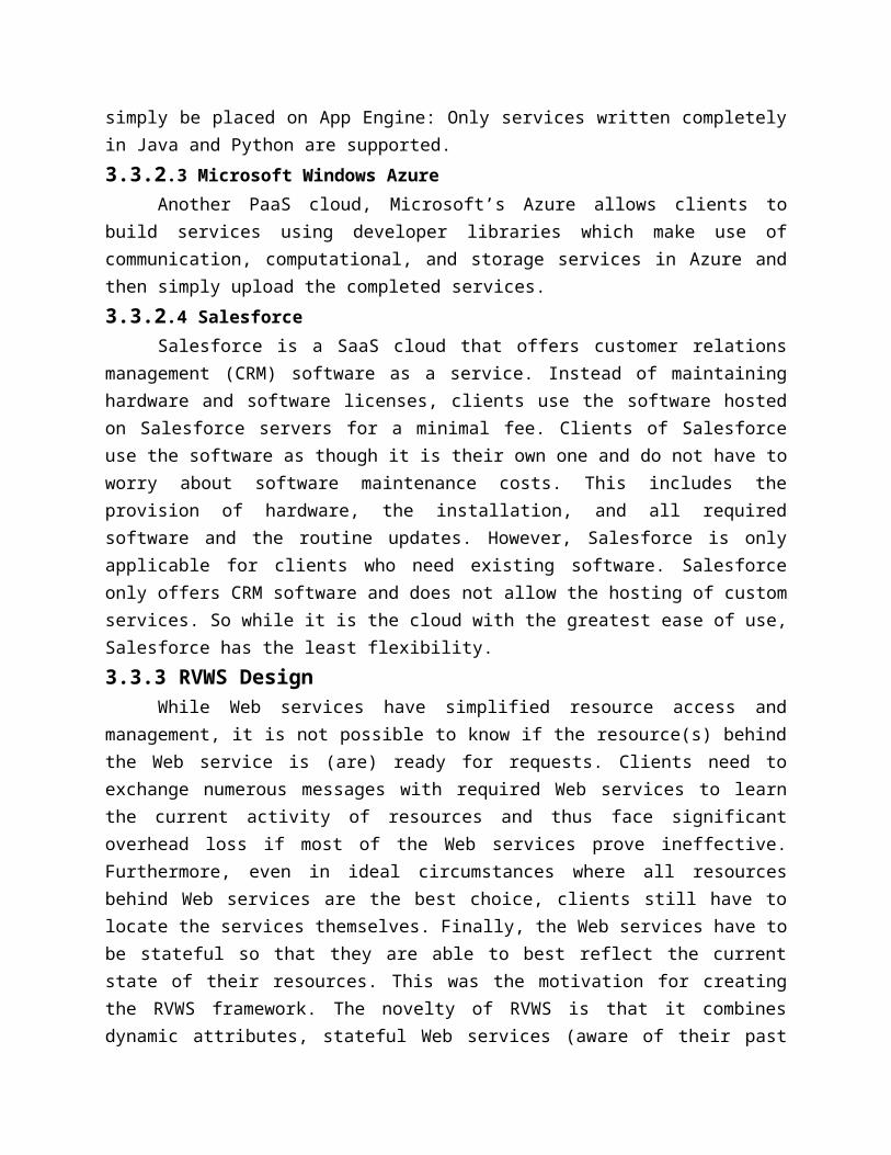
This section describes three secure methods used in three commercial cloud services and discusses their vulnerabilities.Amazon’s Web Service. Amazon provides Infrastructure as a Service (IaaS) with different terms, such as Elastic Compute Cloud (EC1), SimpleDB, Simple Storage Service (S3), and so on. They are supposed to ensure the confidentiality, integrity, and availability of the customers’ applications and data. Following figure presents one of the data processing methods adopted in Amazon’s AWS, which is used to transfer large amounts of data between the AWS cloud and portable storage devices.
AWS data processing procedure
Microsoft Windows Azure. The Windows Azure Platform (Azure) is an Internet-scale cloud services platform hosted in Microsoft data centers, which provides an operating system and a set

of developer services that can be used individually or together. The platform also provides scalable storage service. There are three basic data items: blobs (up to 50 GB), tables, and queues (<8k). In the Azure Storage, based on the blob, table, and queue structures, Microsoft promises to achieve confidentiality of the users’ data. The procedure shown in figure provides security for data accessing to ensure that the data will not be lost. Google App Engine (GAE).
Security data access procedure
The Google App Engine (GAE) provides a powerful distributed data storage service that features a query engine and transactions. An independent third-party auditor, who claims that GAE can be secure under the SAS70 auditing industry standard, issued Google Apps an unqualified SAS70 Type II certification. However, from its on-line storage technical document of lower API, there are only some functions such as GET and PUT. There is no content addressing the issues of securing storage services. The security of data storage is assumed guaranteed using techniques such as by SSL link, based on our knowledge of security method adopted by other services.
Following figure is one of the secure services, called Google Secure Data Connector (SDC), based on GAE. This constructs encrypted connection between the data source and Google Apps.
Illustration of Google SDC working flow

3.4.2.3 Vulnerabilities in Current Cloud ServicesTo provide data integrity, the Azure Storage Service stores the uploaded data
MD5checksum in the database and returns it to the user when the user wants to retrieve the data. Amazon AWS computes the data MD5 checksum and e-mails it to the user for integrity checking. The SDC is based on GAE’s attempt to strengthen Internet authentication using a signed request. If these services are grouped together, the following scheme can be derived.
There are three important concerns in this simple procedure: Confidentiality Integrity Repudiation
3.4.2.4 Bridge the missing linkTAC – Third Authority CertifiedSKS – Secret Key Sharing techniqueNeither TAC nor SKS.Uploading Session1. User: Sends data to service provider with MD5 checksum and MD5Signature by User (MSU).2. Service Provider: Verifies the data with MD5 checksum, if it is valid, the service provider sends back the MD5 and MD5 Signature by Provider (MSP) to user.3. MSU is stored at the user side, and MSP is stored at the service provider side.Once the uploading operation finished, both sides agreed on the integrity of the uploaded data, and each side owns the MD5 checksum and MD5 signature generated by the opposite site. Downloading Session1. User: Sends request to service provider with authentication code.2. Service Provider: Verifies the request identity, if it is valid, the service provider sends back the data with MD5 checksum andMD5 Signature by Provider (MSP) to user.3. User verifies the data using the MD5 checksum.With SKS but without TAC.Uploading Session1. User: Sends data to service provider with MD checksum 1.2. Service Provider: Verifies the data with MD5 checksum, if it is valid, the service provider sends back the MD5 checksum.3. The service provider and the user share the MD5 checksum with SKS.Then, both sides agree on the integrity of the uploaded data, and they share the agreed MD5 checksum, which is used when disputation happens.Downloading Session1. User: Sends request to the service provider with authentication code.2. Service Provider: Verifies the request identity, if it is valid, the service provider sends back the data with MD5 checksum.3. User verifies the data through the MD5 checksum.When disputation happens, the user or the service provider can take the shared MD5 together, recover it, and prove his/her innocence.

With TAC but without SKS.Uploading Session1. User: Sends data to the service provider along with MD5 checksum andMD5 Signature by User (MSU).2. Service Provider: Verifies the data with MD5 checksum, if it is valid, the service provider sends back the MD5 checksum and MD5 Signature by Provider (MSP) to the user.3. MSU and MSP are sent to TAC.On finishing the uploading phase, both sides agree on the integrity of the uploaded data, and TAC owns their agreed MD5 signature.Downloading Session1. User: Sends request to the service provider with authentication code.2. Service Provider: Verifies the request with identity, if it is valid, the service provider sends back the data with MD5 checksum.3. User verifies the data through the MD5 checksum.When disputation happens, the user or the service provider can prove his innocence by presenting the MSU and MSP stored at the TAC.Similarly, there are some special cases. When the service provider is trustworthy, only the MSU is needed; when the user is trustworthy, only the MSP is needed; if each of them trusts the other, the TAC is not needed. Again, the last case is the method adopted in the current cloud computing platforms. When the identity is authenticated, trust is established. With Both TAC and SKS.Uploading Session1. User: Sends data to the service provider with MD5 checksum.2. Service Provider: verifies the data with MD5 checksum.3. Both the user and the service provider send MD5 checksum to TAC.4. TAC verifies the two MD5 checksum values. If they match, the TAC distributes MD5 to the user and the service provider by SKS.Both sides agree on the integrity of the uploaded data and share the same MD5checksum by SKS, and the TAC own their agreed MD5 signatures.Downloading Session1. User: Sends request to the service provider with authentication code.2. Service Provider: Verifies the request identity, if it is valid, the service provider sends back the data with MD5 checksum.3. User verifies the data through the MD5 checksum.When disputation happens, the user or the service provider can prove their innocence by checking the shared MD5 checksum together. If the disputation cannot be resolved, they can seek further help from the TAC for the MD5checksum.Here are the special cases. When the service provider is trustworthy, only the user needs the MD5 checksum; when the user is trustworthy, only the service provider needs MD5 checksum; if both of them can be trusted, the TAC is not needed. This is the method used in the current cloud computing platform.3.4.3 Technologies for Data Security in Cloud Computing

This section presents several technologies for data security and privacy in cloud computing. Focusing on the unique issues of the cloud data storage plat form, this section does not repeat the normal approaches that provide confidentiality, integrity, and availability in distributed data storage applications. Instead, we select to illustrate the unique requirements for cloud computing data security from a few different perspectives:
Database Outsourcing and Query Integrity Assurance Data Integrity in Untrustworthy Storage Web-Application-Based Security Multimedia Data Security Storage
3.4.3.1 Database Outsourcing and Query Integrity AssuranceIn recent years, database outsourcing has become an important component of cloud
computing. Due to the rapid advancements in network technology, the cost of transmitting a terabyte of data over long distances has decreased significantly in the past decade. In addition, the total cost of data management is five to ten times higher than the initial acquisition costs. As a result, there is a growing interest in outsourcing database management tasks to third parties that can provide these tasks for a much lower cost due to the economy of scale. This new outsourcing model has the benefits of reducing the costs for running Database Management Systems (DBMS) independently and enabling enterprises to concentrate on their main businesses. Following figure demonstrates the general architecture of a database outsourcing environment with clients
The database owner outsources its data management tasks, and clients send queries to the untrusted service provider. Let T denote the data to be outsourced. The data T are is preprocessed, encrypted, and stored at the service provider. For evaluating queries, a user rewrites a set of queries Q against T to queries against the encrypted database. Data Privacy Protection. Hacigumus proposed a method to execute SQL queries over encrypted databases. Their strategy is to process as much of a query as possible by the service providers, without having to decrypt the data. Decryption and the remainder of the query processing are performed at the client side. Agrawal proposed an order-preserving encryption scheme for numeric values that allows any comparison operation to be directly applied on encrypted data. Their technique is able to handle updates, and new values can be added without requiring changes in the encryption of other values. Generally, existing methods enable direct execution of encrypted queries on encrypted datasets and allow users to ask identity queries over data of different encryptions. The ultimate goal of this research direction is to make queries in

encrypted databases as efficient as possible while preventing adversaries from learning any useful knowledge about the data. However, researches in this field did not consider the problem of query integrity. Query Integrity Assurance. In addition to data privacy, an important security concern in the database outsourcing paradigm is query integrity. Query integrity examines the trustworthiness of the hosting environment. When a client receives a query result from the service provider, it wants to be assured that the result is both correct and complete, where correct means that the result must originate in the owner’s data and not has been tampered with, and complete means that the result includes all records satisfying the query. Devanbu et al. Authenticate data records using the Merkle hash tree, which is based on the idea of using a signature on the root of the Merkle hash tree to generate a proof of correctness. Studied and compared several signature methods that can be utilized in data authentication, and they identified the problem of completeness but did not provide a solution. Utilized an aggregated signature to sign each record with the information from neighboring records by assuming that all the records are sorted with a certain order. The method ensures the completeness of a selection query by checking the aggregated signature. But it has difficulties in handling multipoint selection query of which the result tuples occupy a noncontiguous region of the ordered sequence.3.4.3.2 Data Integrity in Untrustworthy Storage
While the transparent cloud provides flexible utility of network-based resources, the fear of loss of control on their data is one of the major concerns that prevent end users from migrating to cloud storage services. Actually it is a potential risk that the storage infrastructure providers become self-interested, untrustworthy, or even malicious. There are different motivations whereby a storage service provider could become untrustworthy—for instance, to cover the consequence of a mistake in operation, or deny the vulnerability in the system after the data have been stolen by an adversary.
This section introduces two technologies to enable data owners to verify the data integrity while the files are stored in the remote untrustworthy storage services.
Requirement #1. It should not be a pre-requirement that the verifier has to possess a complete copy of the data to be checked. And in practice, it does not make sense for a verifier to keep a duplicated copy of the content to be verified. As long as it serves the purpose well, storing a more concise contents digest of the data at the verifier should be enough.
Requirement #2. The protocol has to be very robust considering the untrustworthy prover. A malicious prover is motivated to hide the violation of data integrity. The protocol should be robust enough that such a prover ought to fail in convincing the verifier.
Requirement #3. The amount of information exchanged during the verification operation should not lead to high communication overhead.
Requirement #4. The protocol should be computationally efficient.Requirement #5. It ought to be possible to run the verification an unlimited number of
times.A PDP-Based Integrity Checking Protocol. Ateniese et al. Proposed a protocol based on the provable data procession (PDP) technology, which allows users to obtain a probabilistic proof

from the storage service providers. Such a proof will be used as evidence that their data have been stored there. One of the advantages of this protocol is that the proof could be generated by the storage service provider by accessing only a small portion of the whole dataset. At the same time, the amount of the metadata that end users are required to store is also small—that is, O(1). Additionally, such a small amount data exchanging procedure lowers the overhead in the communication channels too. Following figure presents the flow chart of the protocol for provable data possession.
An Enhanced Data Possession Checking Protocol. Sebe et al.] pointed out that the above PDP-based protocol does not satisfy Requirement#2 with 100% probability. An enhanced protocol has been proposed based on the idea of the Diffie_Hellman scheme. It is claimed that this protocol satisfies all five requirements and is computationally more efficient than the PDP-based protocol.

The verification time has been shortened at the setup stage by taking advantage of the trade-offs between the computation times required by the prover and the storage required at the verifier. 3.4.3.3 Web-Application-Based Security
In cloud computing environments, resources are provided as a service over the Internet in a dynamic, virtualized, and scalable way. Through cloud computing services, users access business applications on-line from a Web browser, while the software and data are stored on the servers. Therefore, in the era of cloud computing, Web security plays a more important role than ever. The Web site server is the first gate that guards the vast cloud resources. Since the cloud may operate continuously to process millions of dollars’ worth of daily on-line transactions, the impact of any Web security vulnerability will be amplified at the level of the whole cloud.
Web attack techniques are often referred as the class of attack. When any Web security vulnerability is identified, attacker will employ those techniques to take advantage of the security vulnerability. The types of attack can be categorized in Authentication, Authorization, Client-Side Attacks, Command Execution, Information Disclosure, and Logical Attacks. Due to the limited space, this section introduces each of them briefly. Interested readers are encouraged to explore for more detailed information from the materials cited.Authentication. Authentication is the process of verifying a claim that a subject made to act on behalf of a given principal. Authentication attacks target a Web site’s method of validating the identity of a user, service, or application, including Brute Force, Insufficient Authentication, and Weak Password Recovery Validation. Brute Force attack employs an automated process to guess a person’s username and password by trial and error. In the Insufficient Authentication case, some sensitive content or functionality are protected by “hiding” the specific location in obscure string but still remains accessible directly through a specific URL. The attacker could discover those URLs through a Brute Force probing of files and directories. Many Web sites provide password recovery service. This service will automatically recover the username or password to the user if she or he can answer some questions defined as part of the user registration process. If the recovery questions are either easily guessed or can be skipped, this Web site is considered to be Weak Password Recovery Validation. Authorization. Authorization is used to verify if an authenticated subject can perform a certain operation. Authentication must precede authorization.
For example, only certain users are allowed to access specific content or functionality.Client-Side Attacks. The Client-Side Attacks lure victims to click a link in a malicious Web page and then leverage the trust relationship expectations of the victim for the real Web site. In Content Spoofing, the malicious Web page can trick a user into typing user name and password and will then use this information to impersonate the user.Command Execution. The Command Execution attacks exploit server-side vulnerabilities to execute remote commands on the Web site. Usually, users supply inputs to the Web-site to request services. If a Web application does not properly sanitize user-supplied input before using it within application code, an attacker could alter command execution on the server. Information Disclosure. The Information Disclosure attacks acquire sensitive information about a web site revealed by developer comments, error messages, or well-known file name

conventions. For example, a Web server may return a list of files within a requested directory if the default file is not present. This will supply an attacker with necessary information to launch further attacks against the system. Other types of Information Disclosure includes using special paths such as “.” and “.” for Path Traversal, or uncovering hidden URLs via Predictable Resource Location.Logical Attacks. Logical Attacks involve the exploitation of a Web application’s logic flow. Usually, a user’s action is completed in a multi-step process. The procedural workflow of the process is called application logic. A common Logical Attack is Denial of Service (DoS). DoS attacks will attempt to consume all available resources in the Web server such as CPU, memory, disk space, and so on, by abusing the functionality provided by the Web site. 3.4.3.4 Multimedia Data Security Storage
Multimedia Data Security plays an important role in the data storage to protect multimedia data. Recently, how storage multimedia contents are delivered by both different providers and users has attracted much attentions and many applications. This section briefly goes through the most critical topics in this area. Protection from Unauthorized Replication. Contents replication is required to generate and keep multiple copies of certain multimedia contents. For example, content distribution networks (CDNs) have been used to manage content distribution to large numbers of users, by keeping the replicas of the same contents on a group of geographically distributed surrogates, .Although the replication can improve the system performance, the unauthorized replication causes some problems such as contents copyright, waste of replication cost, and extra control overheads.Protection from Unauthorized Replacement. As the storage capacity is limited, a replacement process must be carried out when the capacity exceeds its limit. It means the situation that a currently stored content must be removed from the storage space in order to make space for the new coming content. However, how to decide which content should be removed is very important. If an unauthorized replacement happens, the content which the user doesn’t want to delete will be removed resulting in an accident of the data loss. Furthermore, if the important content such as system data is removed by unauthorized replacement, the result will be more serious.Protection from Unauthorized Pre-fetching. The Pre-fetching is widely deployed in Multimedia Storage Network Systems between server databases and end users’ storage disks. That is to say, If a content can be predicted to be requested by the user in future requests, this content will be fetched from the server database to the end user before this user requests it, in order to decrease user response time. Although the Pre-fetching shows its efficiency, the unauthorized pre-fetching should be avoided to make the system to fetch the necessary content.3.4.4 OPEN QUESTIONS AND CHALLENGES.
Almost all the current commercial cloud service providers claim that their platforms are secure and robust. On one hand, they adopt robust cipher algorithms for confidentiality of stored data; on the other hand, they depend on network communication security protocols such as SSL, IPSec, or others to protect data in transmission in the network. For the service availability and high performance, they choose virtualization technologies and apply strong authentication and

authorization schemes in their cloud domains. However, as a new infrastructure/platform leading to new application/service models of the future’s IT industry, the requirement for a security cloud computing is different from the traditional security problems. 3.4.4.1 Concerns at Different Levels
The cloud computing environment consists of three levels of abstractions: 1. The cloud infrastructure providers, which is at the back end, own and manage the network infrastructure and resources including hardware devices and system software.2. The cloud service providers, which offer services such as on-demand computing, utility computing, data processing, software services, and platforms for developing application software.3. The cloud consumers, which is at the front end of the cloud computing environment and consists of two major categories of users: (a) application developers, who take advantage of the hardware infrastructure and the software platforms to construct application software for ultimate end-users; and (b) end users, who carry out their daily works using the on-demand computing, software services, and utility services.3.4.4.2 Technical and Nontechnical Challenges
The above analysis has shown that besides technical challenges, the cloud computing platform (infrastructure and service) providers are also required to meet a couple of nontechnical issues—for example, the lack of legal requirements on data security to service providers .
More specifically, the following technical challenges need to be addressed in order to make cloud computing acceptable for common consumers:
Open security profiling of services that is available to end users and verifiable automatically. Service providers need to disclose in detail the levels of specific security properties rather than providing blanket assurances of “secure” services.
The cloud service/infrastructure providers are required to enable end users to remotely control their virtual working platforms in the cloud and monitor others’ access to their data. This includes the capability of fine grained accessing controls on their own data, no matter where the data files are stored and processed. In addition, it is ideal to possess the capability of restricting any unauthorized third parties from manipulating users’ data, including the cloud service provider, as well as cloud infrastructure providers.
Security compliance with existing standards could be useful to enhance cloud security. There must be consistency between the security requirements and/or policies of service consumers and the security assurances of cloud providers.
It is mandatory for the providers to ensure that software is as secure as they claim. These assurances may include certification of the security of the systems in question. A certificate—issued after rigorous testing according to agreed criteria—can ensure the degree of reliability of software in different configurations and environments acclaimed by the cloud providers.
3.5 ANEKA—Integration of Private And Public Clouds

3.5.1 IntroductionA growing interest in moving software applications, services, and even infrastructure
resources from in-house premises to external providers has been witnessed recently. A survey conducted by F1 Networks between June and July 2009 showed that such a trend has now reached a critical mass; and an increasing number of IT managers have already adopted, or are considering adopting, this approach to implement IT operations. This model of making IT resources available, known as Cloud Computing, opens new opportunities to small, medium-sized, and large companies. 3.5.2 Technologies and Tools For Cloud Computing
In this section we will concentrate mostly on the Infrastructure as a Service (IaaS) and Platform as a Service (PaaS) implementations of the cloud computing model by first presenting a subset of the most representative commercial solutions and then discussing the few research projects and platforms, which attracted considerable attention.3.5.3 ANEKA Cloud Platform
Aneka is a software platform and a framework for developing distributed applications on the cloud. It harnesses the computing resources of a heterogeneous network of workstations and servers or data centers on demand.
Aneka provides developers with a rich set of APIs for transparently exploiting these resources by expressing the application logic with a variety of programming abstractions. System administrators can leverage a collection of tools to monitor and control the deployed infrastructure. This can be a public cloud available to anyone through the Internet, a private cloud constituted by a set of nodes with restricted access within an enterprise, or a hybrid cloud where external resources are integrated on demand, thus allowing applications to scale.
There are three classes of services:Execution Services. They are responsible for scheduling and executing applications. Each
of the programming models supported by Aneka defines specialized implementations of these services for managing the execution of a unit of work defined in the model.
Foundation Services. These are the core management services of the Aneka container. They are in charge of metering applications, allocating resources for execution, managing the collection of available nodes, and keeping the services registry updated.
Fabric Services: They constitute the lowest level of the services stack of Aneka and provide access to the resources managed by the cloud. An important service in this layer is the Resource Provisioning Service, which enables horizontal scaling3 in the cloud. Resource provisioning makes Aneka elastic and allows it to grow or to shrink dynamically to meet the QoS requirements of applications.
The container relies on a platform abstraction layer that interfaces it with the underlying host, whether this is a physical or a virtualized resource. This makes the container portable over different runtime environments that feature an implementation of the ECMA 334 and ECMA 335 specifications (such as the .NET framework or Mono).

Aneka framework architecture
3.5.4 ANEKA Resource Provisioning ServiceAneka as a PaaS not only features multiple programming models allowing developers to
easily build their distributed applications, but also provides resource provisioning facilities in a seamless and dynamic fashion. Applications managed by the Aneka container can be dynamically mapped to heterogeneous resources, which can grow or shrink according to the application’s needs. This elasticity is achieved by means of the resource provisioning framework, which is composed primarily of services built into the Aneka fabric layer.
Following figure provides an overview of Aneka resource provisioning over private and public cloud
Aneka identifies two types of private resources: static and dynamic resources. 3.5.4.1 Resource Provisioning ScenarioIt illustrates a possible scenario in which the resource provisioning service becomes important. A private enterprise maintains a private cloud, which consists of (a) five physical dedicated desktops from its engineering department and (b) a small data center managed by Xen Hypervisor providing virtual machines with the maximum capacity of 12 VMs.
Aneka resource provisioning over private and public clouds
In most of the cases, this setting is able to address the computing needs of the enterprise. In the case of peak computing demand, additional resources can be provisioned by leveraging the virtual public infrastructure. For example, a mission critical application could require at least 30 resources to complete within an hour, and the customer is willing to spend a maximum of 5 dollars to achieve this goal. In this case, the Aneka Resource Provisioning service becomes a fundamental infrastructure component to address this scenario.
Use case of resource provisioning under Aneka
3.5.5 Hybrid Cloud ImplementationCurrently, there is no widely accepted standard for provisioning virtual infrastructure
from Infrastructure as a Service (IaaS) providers, but each provider exposes its own interfaces and protocols. Hence, it is not possible to seamlessly integrate different providers into one single infrastructure. The resource provisioning service implemented in Aneka addresses these issues and abstracts away the differences of providers’ implementation. In this section we will briefly review what the desired features of a hybrid cloud implementation are and then we will give a

closer a look at the solution implemented in Aneka together with a practical application of the infrastructure developed.3.5.5.1 Design and Implementation Guidelines
The particular nature of hybrid clouds demands additional and specific functionalities that software engineers have to consider while designing software systems supporting the execution of applications in hybrid and dynamic environments. These features, together with some guidelines on how to implement them, are presented in the following:
Support for Heterogeneity. Hybrid clouds are produced by heterogeneous resources such as clusters, public or private virtual infrastructures, and workstations. In particular, for what concerns a virtual machine manager, it must be possible to integrate additional cloud service providers (mostly IaaS providers) without major changes to the entire system design and codebase. Hence, the specific code related to a particular cloud resource provider should be kept isolated behind interfaces and within pluggable components.
Support for Dynamic and Open Systems. Hybrid clouds change their composition and topology over time. They form as a result of dynamic conditions such as peak demands or specific Service Level Agreements attached to the applications currently in execution. An open and extensible architecture that allows easily plugging new components and rapidly integrating new features is of a great value in this case. Specific enterprise architectural patterns can be considered while designing such software systems. In particular, inversion of control and, more precisely, dependency injection1 in component-based systems is really helpful.
Support for Basic VM Operation Management. Hybrid clouds integrate virtual infrastructures with existing physical systems. Virtual infrastructures are produced by virtual instances. Hence, software frameworks that support hypervisor-based execution should implement a minimum set of operations. They include requesting a virtual instance, controlling its status, terminating its execution, and keeping track of all the instances that have been requested.
Support for Flexible Scheduling Policies. The heterogeneity of resources that constitute a hybrid infrastructure naturally demands for flexible scheduling policies. Public and private resources can be differently utilized, and the workload should be dynamically partitioned into different streams according to their security and quality of service (QoS) requirements. There is then the need of being able to transparently change scheduling policies over time with a minimum impact on the existing infrastructure and almost now downtimes. Configurable scheduling policies are then an important feature.
Support for Workload Monitoring. Workload monitoring becomes even more important in the case of hybrid clouds where a subset of resources is leased and resources can be dismissed if they are no longer necessary. Workload monitoring is an important feature for any distributed middleware, in the case of hybrid clouds, it is necessary to integrate this feature with scheduling policies that either directly or indirectly govern the management of virtual instances and their leases.3.5.5.2 Aneka Hybrid Cloud Architecture

The Resource Provisioning Framework represents the foundation on top of which Aneka-based hybrid clouds are implemented. In this section we will introduce the components that compose this framework and briefly describe their interactions.
The resource provisioning infrastructure is represented by a collection of resource pools that provide access to resource providers, whether they are external or internal, and managed uniformly through a specific component called a resource pool manager. A detailed description of the components follows:
System architecture of the Aneka Resource Provisioning Framework
Resource Provisioning Service. This is an Aneka-specific service that implements the service interface and wraps the resource pool manager, thus allowing its integration within the Aneka container.
Resource Pool Manager. This manages all the registered resource pools and decides how to allocate resources from those pools. The resource pool manager provides a uniform interface for requesting additional resources from any private or public provider and hides the complexity of managing multiple pools to the Resource Provisioning Service.
Resource Pool. This is a container of virtual resources that mostly come from the same resource provider. A resource pool is in charge of managing the virtual resources it contains and eventually releasing them when they are no longer in use. Since each vendor exposes its own specific interfaces, the resource pool (a) encapsulates the specific implementation of the communication protocol required to interact with it and (b) provides the pool manager with a unified interface for acquiring, terminating, and monitoring virtual resources

3.5.5.3 Use Case— The Amazon EC2 Resource PoolAmazon EC1 is one of the most popular cloud resource providers. At the time of writing
it is listed among the top 10 companies providing cloud computing services. It provides a Web service interface for accessing, managing, and controlling virtual machine instances. The Web-service-based interface simplifies the integration of Amazon EC2 with any application. This is the case of Aneka, for which a simple Web service client has been developed to allow the interaction with EC1. In order to interact with Amazon EC2, several parameters are required:
User Identity. This represents the account information used to authenticate with AmazonEC2.The identity is constituted by a pair of encrypted keys that are the access key and the secret key. These keys can be obtained from the Amazon Web services portal once the user has signed in, and they are required to perform any operation that involves Web service access.
Resource Identity. The resource identity is the identifier of a public or a private Amazon Machine Image (AMI) that is used as template from which to create virtual machine instances.
Resource Capacity. This specifies the different type of instance that will be deployed byAmazonEC2. Instance types vary according to the number of cores, the amount of memory, and other settings that affect the performance of the virtual machine instance. Several types of images are available, those commonly used are: small, medium, and large. The capacity of each type of resource has been predefined by Amazon and is charged differently.3.5.5.4 Implementation Steps for Aneka Resource Provisioning Service
The resource provisioning service is a customized service which will be used to enable cloud bursting by Aneka at runtime. Following figure demonstrates one of the application scenarios that utilize resource provisioning to dynamically provision virtual machines from Amazon EC2 cloud. The general steps of resource provisioning on demand in Aneka are the following:
The application submits its tasks to the scheduling service, which, in turns, adds the tasks into the scheduling queue.
The scheduling algorithm finds an appropriate match between a task and a resource. If the algorithm could not find enough resources for serving all the tasks, it requests extra resources from the scheduling service.
The scheduling service will send a Resource Provision Message to provision service and will ask provision service to get X number of resources as determined by the scheduling algorithm.
Upon receiving the provision message, the provision service will delegate the provision request to a component called resource pool manager, which is responsible for managing various resource pools. A resource pool is a logical view of a cloud resource provider, where the virtual machines can be provisioned at runtime. Aneka resource provisioning supports multiple resource pools such as Amazon EC1 pool and Citrix Xen serverpool.
The resource pool manager knows how to communicate with each pool and will provision the requested resources on demand. Based on the requests from the provision service, the pool manager starts X virtual machines by utilizing the predefined virtual machine template already configured to run Aneka containers.

Aneka resource provisioning (cloud bursting) over Amazon EC2
A worker instance of Aneka will be configured and running once a virtual resource is started. All the work instances will then connect to the Aneka master machine and will register themselves with Aneka membership service.
The scheduling algorithm will be notified by the membership service once those work instances join the network, and it will start allocating pending tasks to them immediately.
Once the application is completed, all the provisioned resources will be released by the provision service to reduce the cost of renting the virtual machine.
3. 6 COMETCLOUD: An Autonomic Cloud Engine3.6.1 Introduction
Clouds typically have highly dynamic demands for resources with highly heterogeneous and dynamic workloads. 3.6.2 CometCloud ArchitectureCometCloud is an autonomic computing engine for cloud and grid environment. It is based on the Comet decentralized coordination substrate, and it supports highly heterogeneous and dynamic cloud/grid infrastructure, integration of public/private clouds, and autonomic cloudbursts. 3.6.2.1 CometCloud Layered Abstractions
A schematic overview of the CometCloud architecture is presented in following figure. The infrastructure layer uses the Chord self-organizing overlay, and the Squid information discovery and content-based routing substrate built on top of Chord.

The ComeCloud architecture for autonomic cloudbursts
The routing engine supports flexible content-based routing and complex querying using partial keywords, wildcards, or ranges. It also guarantees that all peer nodes with data elements that match a query/message will be located. Nodes providing resources in the overlay have different roles and, accordingly, different access privileges based on their credentials and capabilities.
This layer also provides replication and load balancing services, and it handles dynamic joins and leaves of nodes as well as node failures. Every node keeps the replica of its successor node’s state, and it reflects changes to this replica whenever its successor notifies it of changes. It also notifies its predecessor of any changes to its state. If a node fails, the predecessor nod emerges the replica into its state and then makes a replica of its new successor. If a new node joins, the joining node’s predecessor updates its replica to reflect the joining node’s state, and the successor gives its state information to the joining node.
To maintain load balancing, load should be redistributed among the nodes whenever a node joins and leaves. The service layer provides a range of services to supports autonomics at the programming and application level. This layer supports the Linda-like tuple space coordination model, and it provides a virtual shared-space abstraction as well as associative access primitives. The basic coordination primitives are listed below:
out (ts, t): a nonblocking operation that inserts tuple t into space ts. in (ts, t’): a blocking operation that removes a tuple t matching template t’ from
the space ts and returns it. rd (ts, t’): a blocking operation that returns a tuple t matching template t’ from the
space ts. The tuple is not removed from the space.3.6.2.2 Comet Space
In Comet, a tuple is a simple XML string, where the first element is the tuple’s tag and is followed by an ordered list of elements containing the tuple’s fields. Each field has a name

followed by its value. The tag, field names, and values must be actual data for a tuple and can contain wildcards (“*”) for a template tuple. This lightweight format is flexible enough to represent the information for a wide range of applications and can support rich matching relationships. Furthermore, the cross-platform nature of XML makes this formats ui for information exchange in distributed heterogeneous environments. A tuple in Comet can be retrieved if it exactly or approximately matches a template tuple. Exact matching requires the tag and field names of the template tuple to be specified without any wildcard, as in Linda. However, this strict matching pattern must be relaxed in highly dynamic environments, since applications (e.g., service discovery) may not know exact tuple structures. Comet supports tuple retrievals with incomplete structure information using approximate matching, which only requires the tag of the template tuple be specified using a keyword or a partial keyword. 3.6.3 Autonomic Behavior of Cometcloud3.6.3.1 Autonomic Cloud bursting
The goal of autonomic cloudbursts is to seamlessly and securely integrate private enterprise clouds and data centers with public utility clouds on-demand, to provide the abstraction of resizable computing capacity. It enables the dynamic deployment of application components (which typically run on internal organizational compute resources) onto a public cloud to address dynamic workloads, spikes in demands, and other extreme requirements. Furthermore, given the increasing application and infrastructure scales, as well as their cooling, operation, and management costs, typical over-provisioning strategies are no longer feasible.
Autonomic cloudbursts using CometCloud

Autonomic cloudbursts can leverage utility clouds to provide on-demand scale-out and scale-in capabilities based on a range of metrics. Key motivations for autonomic cloudbursts include:
Load Dynamics. Application workloads can vary significantly. This includes the number of application tasks as well the computational requirements of a task. The computational environment must dynamically grow (or shrink) in response to these dynamics while still maintaining strict deadlines.
Accuracy of the Analytics. The required accuracy of risk analytics depends on a number of highly dynamic market parameters and has a direct impact on the computational demand—for example the number of scenarios in the Monte Carlo VaR formulation. The computational environment must be able to dynamically adapt to satisfy the accuracy requirements while still maintaining strict deadlines.
Collaboration of Different Groups. Different groups can run the same application with different dataset policies. Here, policy means user’s SLA bounded by their condition such as time frame, budgets, and economic models. As collaboration groups join or leave the work, the computational environment must grow or shrink to satisfy their SLA.
Economics. Application tasks can have very heterogeneous and dynamic priorities and must be assigned resources and scheduled accordingly. Budgets and economic models can be used to dynamically provision computational resources based on the priority and criticality of the application task. For example, application tasks can be assigned budgets and can be assigned resources based on this budget. The computational environment must be able to handle heterogeneous and dynamic provisioning and scheduling requirements.
Failures. Due to the strict deadlines involved, failures can be disastrous. The computation must be able to manage failures without impacting application quality of service, including deadlines and accuracies.3.6.3.2 Autonomic Cloud bridging
Autonomic cloud bridging is meant to connect CometCloud and a virtual cloud which consists of public cloud, data center, and grid by the dynamic needs of the application. The clouds in the virtual cloud are heterogeneous and have different types of resources and cost policies, besides, the performance of each cloud can change over time by the number of current users. Hence, types of used clouds, the number of nodes in each cloud, and resource types of nodes should be decided according to the changing environment of the clouds and application’s resource requirements.
Following figure shows an overview of the operation of the CometCloud based autonomic cloudbridging.
The scheduling agent manages autonomic cloudbursts over the virtual cloud, and there can be one or more scheduling agents. A scheduling agent is located at a robust/secure master site. If multiple collaborating research groups work together and each group requires generating tasks with its own data and managing the virtual cloud by its own policy, then it can have a separate scheduling agent in its master site. The requests for tasks generated by the different sites are logged in the CometCloud virtual shared space that spans master nodes at each of the sites.

These tasks are then consumed by workers, which may run on local computational nodes at the site, a shared data center, and a grid or on a public cloud infrastructure.
Overview of the operation of autonomic cloudbridging
A scheduling agent manages QoS constraints and autonomic cloudbursts of its site according to the defined policy. The workers can access the space using appropriate credentials, access authorized tasks, and return results back to the appropriate master indicated in the task itself.
A scheduling agent manages autonomic cloudbridging and guarantees QoS within user policies. Autonomic cloudburst is represented by changing resource provisioning not to violate defined policy. We define three types of policies.
Deadline-Based. When an application needs to be completed as soon as possible, assuming an adequate budget, the maximum required workers are allocated for the job.
Budget-Based. When a budget is enforced on the application, the number of workers allocated must ensure that the budget is not violated.
Workload-Based. When the application workload changes, the number of workers explicitly defined by the application is allocated or released.3.6.3.3 Other Autonomic Behaviors Fault-Tolerance. Supporting fault-tolerance during runtime is critical to keep the application’s deadline. We support fault-tolerance in two ways which are in the infrastructure layer and in the programming layer. The replication substrate in the infrastructure layer provides a mechanism to keep the same state as that of its successor’s state, specifically coordination space and overlay information. Following figure shows the overview of replication in the overlay.

Replication overview in the CometCloud overlay
Every node has a local space in the service layer and a replica space in the infrastructure layer. When a tuple is inserted or extracted from the local space, the node notifies this update to its predecessor and the predecessor updates the replica space. Hence every node keeps the same replica of its successor’s local space. When a node fails, another node in the overlay detects the failure and notifies it to the predecessor of the failed node. Then the predecessor of the failed node merges the replica space into the local space, and this makes all the tuples from the failed node recovered. Also the predecessor node makes a new replica for the local space of its new successor. We also support fault tolerance in the programming layer. Even though replica of each node is maintained, some tasks can be lost during runtime because of network congestion or task generation during failure. To address this issue, the master checks the space periodically and regenerates lost tasks.Load Balancing. In a cloud environment, executing application requests on underlying grid resources consists of two key steps. The first, which we call VM Provisioning, consists of creating VM instances to host each application request, matching the specific characteristics and requirements of the request. The second step is mapping and scheduling these requests onto distributed physical resources (Resource Provisioning). Most virtualized data centers currently provide a set of general-purpose VM classes with generic resource configurations, which quickly become insufficient to support the highly varied and interleaved workloads. Furthermore, clients can easily under- or overestimate their needs because of a lack of understanding of application requirements due to application complexity and/or uncertainty, and this often results in over-provisioning due to a tendency to be conservative.3.6.4 Overview of CometCloud-Based Applications
In this section, we describe two types of applications which are VaR for measuring the risk level of a firm’s holdings and image registration for medical informatics. A VaR calculation should be completed within the limited time, and the computational requirements for the calculation can change significantly.
Besides, the requirement for additional computation happens irregularly. Hence, for VaR we will focus on how autonomic cloudbursts work for dynamically changing workloads.
Image registration is the process to determine the linear/nonlinear mapping T between two images of the same object or similar objects that are acquired at different time, or from

different perspectives. Besides, because a set of image registration methods are used by different (geographically distributed) research groups to process their locally stored data, jobs can be injected from multiple sites.
Another distinguished difference between two applications is that data size of image registration is much larger than that of VaR. For a 3D image, the image size is usually a few tens of megabytes. Hence, image data should be separated from its task tuple, and instead it locates on a separate storage server and its location is indicated in the task tuple.
For image registration, because it usually needs to be completed as soon as possible within budget limit, we will focus on how CometCloud works using budget-based policy.3.6.4.1 Value at Risk (VaR) Monte Carlo
VaR is a very powerful measure used to judge the risk of portfolios of financial instruments. The complexity of the VaR calculation stems from simulating portfolio returns. To accomplish this, Monte Carlo methods are used to “guess” what the future state of the world may look like. Guessing a large number of times allows the technique to encompass the complex distributions and the correlations of different factors that drive portfolio returns into a discreet set of scenarios. Each of these Monte Carlo scenarios contains a state of the world comprehensive enough to value all instruments in the portfolio, thereby allowing us to calculate a return for the portfolio under that scenario.3.6.4.2 Image Registration
Nonlinear image registration is the computationally expensive process to determine the mapping T between two images of the same object or similar objects acquired at different time, in different position or with different acquisition parameters or modalities. Both intensity/area based and landmark based methods have been reported to be effective in handling various registration tasks. 3.6.5 Implementation and Evaluation
In this section, we evaluate basic CometCloud operations first, and then compare application runtime varying the number of nodes after describing how the applications were implemented using CometCloud. Then we evaluate VaR using workload-based policy and Image registration using budget-based policy. Also we evaluate CometCloud with/without a scheduling agent. For deadline-based policy that doesn’t have a budget limit, because it allocates as many workers as possible, we applied it just to compare results with and without scheduling agent for budget-based policy.3.6.5.1 Evaluation of Comet Cloud Basic Comet Cloud Operations.
In this experiment we evaluated the costs of basic tuple insertion and exact retrieval operations on the Rutgers cloud. Each machine was a peer node in the CometCloud overlay and the machines formed a single CometCloud peer group. The size of the tuple in the experiment was fixed at 200 bytes. Aing-pong-like process was used in the experiment, in which an application process inserted a tuple into the space using the out operator, read the same tuple

using the rd operator, and deleted it using the in operator. In the experiment, the out and exact matching in/rd operators used a three-dimensional information space.
For an out operation, the measured time corresponded to the time interval between when the tuple was posted into the space and when the response from the destination was received. For an in or rd operation, the measured time was the time interval between when the template was posted into the space and when the matching tuple was returned to the application, assuming that a matching tuple existed in the space. This time included the time for routing the template, matching tuples in the repository, and returning the matching tuple. The average performances were measured for different system sizes.Overlay Join Overhead. To share the Comet space, a node should join the CometCloud overlay and each node should manage a finger to keep track of changing neighbors. When a node joins the overlay, it first connects to a predefined bootstrap node and sends its information such as IP address to the bootstrap. Then the bootstrap node makes a finger for the node and sends it back to the node. Hence, the more nodes join the overlay at the same time, the larger join overhead happens.3.6.5.2 Application Runtime
All tasks generated by the master are inserted into the Comet space and each should be described by XML tags that are described differently for the purpose of an application. Data to be computed can be included in a task or outside of the task such as in a file server. To show each case, let VaR tasks include data inside the tuple and image registration tasks include data outside of the tuple because image data are relatively larger than VaR data. A typical out task for VaR is described as shown below.
<VarAppTask><TaskId>taskid</TaskId><DataBlock>data_blocks</ DataBlock ><MasterNetName>master_name</ MasterNetName>
</ VarAppTask >The following figure shoes the total application runtime of CometCloud
(a) VaR (b) Image registration on Amazon EC2 for different number of scenarios

Evaluation of CometCloud-based applications on Amazon EC2 (a) VaR. (b) Image registration
3.6.5.3 Autonomic Cloudbursts Behaviors VaR Using Workload-Based Policy.
In this experiment, autonomic cloudburst is represented by the number of changing workers. When the application workload increases (or decreases), a predefined number of workers are added (or released), based on the application workload. Specifically, we defined workload-specific and workload-bounded policies.
In workload-specific, a user can specify the workload that nodes are allocated or released. In workload bounded, whenever the workload increases by more than a specified
threshold, a predefined number of workers is added. Similarly, if the workload decreases by more than the specified threshold, the predefined number of workers is released.Image Registration Using Budget-Based Policy. The virtual cloud environment used for the experiments consisted of two research sites located at Rutgers University and the University of Medicine and Dentistry of New Jersey: one public cloud (i.e. Amazon Web Service (AWS) EC2) and one private datacenter at Rutgers (i.e.TW). The two research sites hosted their own image servers and job queues, and workers running on EC2 or TW access these image servers to get the image described in the task assigned to them( Figure). Evaluation of CometCloud-Based Image Registration Application Enabled Scheduling Agent. The results from the experiments are plotted in .Note that since the scheduling interval is 1 min, the x axis corresponds to both time (in minutes) and the scheduling iteration number. Initially, the CometCloud scheduling agent does not know the cost of completing a task. Hence, it initially allocated 6 nodes each from TW and EC2. In the beginning, since the budget is sufficient, the scheduling agent tries to allocate TW nodes even though they cost more than EC2 node.
Policy-based autonomic cloudburst using CometCloud. (a)Workload-specific policy. (b) Workload-bounded policy
In the second scheduling iteration, there are 460 tasks still remaining, and the agent attempts to allocate 180 TW nodes and 280 EC2 nodes to finish all tasks as soon as possible within the available budget. If TW and EC2 could provide the requested nodes, all the tasks would be completed by next iteration. However, since the maximum available number of TW nodes is only 25, it allocates these 25 TW nodes and estimates that a completion time of 7.2 iterations. The agent then decides on the number of EC2 workers to be used based on the estimated rounds. Comparison of Execution Time and Used Budget with/without Scheduling Agent.

Comparison of Execution Time and Used Budget with/without Scheduling Agent. Following figure shows a comparison of execution time and used budget with/without the CometCloud scheduling agent
Experimental evaluation of medical image registration using CometCloud – comparison of performance and costs with/without autonomic scheduling (a) Execution time varying the number of nodes of EC2 and TW. (b) Used budget over time varying the number of nodes for EC2 and Tw
3.7 T-SYSTEMS’ Cloud-Based Solutions For Business Applications3.7.1 Introduction
T-Systems is one of Europe’s largest ICT service providers. It offers a wide range of IT, telecommunications, and integrated ICT services, and it boasts extensive experience in managing complex outsourcing projects. The company offers hosting and other services from its 75 data centers with over 50,000 servers and over 125.000 MIPS—in Europe, Asia, the Americas and Africa. 3.7.2 What Enterprises Demand of Cloud Computing
Whether operated in-house or by an external provider, ICT is driven by two key factors (Figure): cost pressure and market pressure. Both of these call for increases in productivity.3.7.2.1 Changing Markets
Today’s markets are increasingly dynamic. Products and skills rapidly become obsolete, eroding competitiveness. So incumbents need to find and implement new ideas at an ever faster pace. Also, new businesses are entering the market more rapidly, and they are extending their portfolios by forging alliances with other players.3.7.2.2 Increased Productivity
Today, enterprise ICT and business processes are closely interwoven—so that the line between processes and technology is becoming blurred. As a result, ICT is now a critical success factor: It significantly influences competitiveness and value creation. The impact of fluctuations in the quality of ICT services (for example, availability) is felt immediately. The no availability of ERP (enterprise resource planning) and e-mail systems brings processes grinding to a halt and makes collaboration impossible. And the resulting time-to-market delays mean serious competitive disadvantage.

The route to cloud computing – industrialization of IT
3.7.2.3 Rising Cost PressureGlobalization opens up new markets. But it also means exposure to greater competition.
Prices for goods and services are falling at the same time that the costs for power, staff, and raw materials are rising. The financial crisis has aggravated the situation, with market growth slowing or stagnating. To master these challenges, companies have to improve their cost structures.
This generally means cutting costs. Staff downsizing and the divestment of loss-making units are often the preferred options. However, replacing fixed costs with variable costs can also contribute significantly—without resorting to sensitive measures such as layoffs. This improves liquidity. Money otherwise tied up in capital investment can be put to good use elsewhere. In extreme cases, this can even avert insolvency; most commonly, the resulting liquidity is used to increase equity, mitigating financial risk.
A radical increase in the flexibility of the ICT landscapes can deliver significant long-term benefits. It fundamentally transforms cost structures, since ICT-related expenses are a significant cost factor. ICT spending (for example, administration and energy costs) offers considerable potential for savings.3.7.3 Dynamic ICT Services
Expectations differ considerably, depending on company size and industry. For example, a pharmaceuticals multinational, a traditional midsize retailer, and a startup will all have very different ICT requirements, particularly when it comes to certification.
However, they all face the same challenges: the need to penetrate new markets, to launch new services, to supply sales models, or to make joint offerings with partners. This is where dynamic ICT delivers tangible benefits.3.7.3.1 Steps toward Industrialized ICT
Standardization and automation greatly reduce production costs and increase the efficiency and flexibility of ICT. However, they come at a price: There is less scope for

customization. This is something that everyone with a personal e-mail account from one of the big providers has encountered. Services of this kind fulfill their purpose, but offer only very stripped-down functionality and are usually free of charge. More sophisticated e-mail solutions are available only via fee-based “premium” offerings. In other words, lower costs and simpler processes go hand in hand. And this is why companies have to streamline their processes. When it comes to standardization, ICT service providers focus on the technology while businesses focus on services and processes.3.7.3.2 Customization through Modularization
Modular production enables ICT to be tailored to customers’ specific requirements—in conjunction with standardization. Modularization allows providers to pool resources as the basis for delivering the relevant services .Modularization is essentially a set of standardized individual modules that can be combined. The resulting combinations give rise to sophisticated applications tailored to the needs of the specific company. Standardized interfaces (e.g., APIs) between individual modules play a pivotal role. And one of the great strengths of modules is their reusability. The more easily and flexibly such modules can be combined, the greater the potential benefits. Providers have to keep the number of modules as low as possible while meeting as many of their customers’ requirements as possible, and this is far from easy.3.7.3.3 Integrated Creation of ICT Services
Each of the elements outlined above can have significant advantages. But only an integrated approach to creating ICT services—combining standardization, automation and modularization—can deliver the entire range of benefits. This gives the provider standardized, automated production processes and enables the desired services to be delivered to the customer quickly and flexibly.
In the context of outsourcing, this form of industrialization yields its full potential when providers and users have a close, two-way relationship with corresponding connectivity. This enables businesses to play an active part in production (ICT supply chain), tailoring ICT services to their changing needs. However, the technology that supports this relationship must be based on standards. Cloud computing promises to make switching to a different provider quick and easy, but that is only possible if users are careful to avoid provider lock-in.3.7.4 Importance of Quality and Security in Clouds3.7.4.1 Quality (End-to-End SLAs)
If consumers’ Internet or ICT services are unavailable, or data access is slow, the consequences are rarely serious. But in business, the non-availability of a service can have a grave knock-on effect on entire mission-critical processes—bringing production to a standstill, or preventing orders from being processed. In such instances, quality is of the essence. The user is aware of the performance of systems as a whole, including network connectivity. In complex software applications, comprising multiple services and technical components, each individual element poses a potential risk to the smooth running of processes. Cloud-service providers therefore have to offer end-to-end availability, backed by clearly defined SLAs.3.7.4.2 Compliance and Security

Compliance and security are increasingly important for cloud-computing providers. Security has been the subject of extensive media coverage and debate. And surveys consistently pinpoint it as the greatest obstacle to cloud computing. In a 2008 cio.com study, IT decision-makers cited security and loss of control over data as the key drawbacks of cloud computing.Consumer Cloud versus Enterprise Cloud. The Internet has given rise to new forms of behavior, even when concluding contracts on-line. When presented with general terms and conditions, many consumers simply check the relevant box and click “OK,” often not realizing that they are entering into a legally binding agreement. Standard contracts are now commonly used for consumer services offered from the cloud. However, this does not meet the demands of businesses. Cloud Computing from an Enterprise Perspective. With this in mind, businesses should insist on comprehensive, watertight contracts that include provisions for the recovery and return of their data, even in the event of provider bankruptcy. Moreover, they should establish the country where servers and storage systems are located. Cloud principles notwithstanding, services still have to be performed and data stored at specific physical locations. Where data are located determines whose law applies and also determines which government agencies can access it. In addition to these “hard” factors, enterprises have to consider that data-privacy cultures differ from country to country.What Enterprises Need. Cloud computing and applicable ICT legislation are based on diametrically opposed principles. The former is founded on liberalism and unfettered development—in this case, of technical opportunities. The latter imposes tight constraints on the handling of data and services, as well as on the relationship between customers and providers. And it seems unlikely that these two perspectives will be reconciled in the near future.
Cloud providers have to meet the requirements of the law and of customers alike. As a rule, this leads them to abandon some principles of “pure” cloud computing—and to adopt only those elements that can be aligned with applicable legislation and without risk. However, deployment scenarios involving services from a public cloud are not inconceivable. So providers have to critically adapt cloud principles.3.7.5 Dynamic Data Center—Producing Business-Ready, Dynamic Ict Services3.7.5.1 Flexibility across All Modules
Agility at the infrastructure level alone is not enough to provide fast, flexible ICT services. Other dynamic levels and layers are also required. Ultimately, what matters to the user is the flexibility of the system or service as a whole. So service quality is determined by the slowest component. Toward Dynamic, Flexible ICT Services. The first step is to standardize the customer’s existing environment. IT systems running different software releases have to be migrated, often to a single operating system. Hardware also has to be standardized—for example, by bringing systems onto a specific processor generation (such as x41). Eliminating disparate operating systems and hardware platforms at this stage makes it considerably easier to automate further down the line.

The second step is technical consolidation. This not only reduces the number of physical servers, but also slims down data storage. Identical backup and restore mechanisms are introduced at this stage; and small, uneconomical datacenters are closed.
The third step involves separating the logical from the physical.3.7.5.2 T-Systems’ Core Cloud Modules: Computing, Storage Computing. The computing pool is based on server farms located in different data centers. Logical server systems are created automatically at these farms. The server systems comply with predefined standards. They are equipped with the network interface cards required for communications and integration with storage systems. No internal hard drives or direct-attached storage systems are deployed.
The configuration management database (CMDB) plays a key role in computing resource pools (Figure). This selects and configures the required physical server (1). Once a server has been selected from the pool, virtualization technology is selected in line with the relevant application and the demands it has to meet (2). At the same time, the configuration requirements are sent to the network configuration management system (3) and to the storage configuration management system (4). Once all the necessary elements are in place, the storage systems are mounted on the servers, after which the operating-system images are booted (5).
Provision of computing resourcesStorage resources: backup-integrated, read-only, and archive storage
Applications are also virtualizedStorage. The necessary storage is provided and configured in much the same way as the computing resources. (Following figure)Backup-Integrated Storage. In addition to storage resources, backups are necessary to safeguard against data lossArchive and Other Storage. Archive systems are also available for long-term data storage. Communications. The computing and storage modules are integrated via an automatically configured LAN or corresponding virtual networks (VPNs). The servers deployed in the

computing module are equipped with multiple network cards as standard. Depending on requirements, these are grouped to form the necessary networks.Networks are segregated from each other by means of VPN technology. Backup-integrated storage eliminates the need for a separate backup network. Customer Network. Access for customers is provided via Internet/VPN connections. Services are assigned to companies by means of unique IP addresses.
As standard, access to Dynamic Data Centers is protected via redundant, clustered firewalls. Various versions are available to cater to a range of different customer and application requirements. Virtual firewalls are configured automatically. Due to the high level of standardization, access is entirely IP-based.
Storage resources: backup-integrated, read-only, and archive storage.
Storage and Administration Network. A separate storage network is provided for accessing operating-system images, applications, and customer and archive data. Configuration is handled automatically. An additional network, segregated from the others, is available for managing IT components. Used purely for systems configuration and other administration tasks, this network has no access to the customer’s data or content.3.7.5.3 Dynamic Services—A Brief Overview
The Dynamic Data Center concept underlies all T-Systems Dynamic Services. All the resources required by a given service are automatically provided by the data center. This lays the foundations for a portfolio of solutions aimed at business customers. Dynamic Applications for Enterprises. Enterprises require applications that support specific processes. This applies both to traditional outsourcing and to business relationships in the cloud. T-Systems has tailored its portfolio to fulfill these requirements.
Communications and Collaboration. These are key components for any company. Work on projects often entails frequent changes in user numbers. As a result, enterprises need flexible means of handling communications and collaboration. T-Systems offers the two

leading e-mail systems, Microsoft Exchange and IBM Lotus Domino via Dynamic Services, ensuring their rapid integration into existing environments.
ERP and CRM. Dynamic systems are available to support core ERP and CRM processes. T-Systems offers SAP and Navision solutions in this space.
Development and Testing. Software developers often need access—at short notice and for limited periods of time—to server systems running a variety of operating system versions and releases. Dynamic Services offer the flexibility needed to meet these demands. Configured systems that are not currently required can be locked and mothballed. So when computing resources are no longer needed, no further costs are incurred. That is the advantage of Dynamic Services for developers.
Middleware. When it comes to middleware, Dynamic Services can lay the foundation for further services
Front-Ends and Devices. Not only business applications, but also users’ PC systems, can be provided via the cloud
3.8 Workflow Engine for Clouds3.8.1 Introduction
A workflow models a process as consisting of a series of steps that simplifies the complexity of execution and management of applications. Scientific workflows in domains such as high-energy physics and life sciences utilize distributed resources in order to access, manage, and process a large amount of data from a higher level. Processing and managing such large amounts of data require the use of a distributed collection of computation and storage facilities. These resources are often limited in supply and are shared among many competing users. The recent progress in virtualization technologies and the rapid growth of cloud computing services have opened a new paradigm in distributed computing for utilizing existing (and often cheaper) resource pools for on demand and scalable scientific computing. Scientific Workflow Management Systems (WfMS) need to adapt to this new paradigm in order to leverage the benefits of cloud services.3.8.2 Background
Over the recent past, a considerable body of work has been done on the use of workflow systems for scientific applications. Yu and Buyya provide a comprehensive taxonomy of workflow management systems based on workflow design, workflow scheduling, fault management, and data movement. They characterize and classify different approaches for building and executing workflows on Grids. They also study existing grid workflow systems highlighting key features and differences.3.8.3 Workflow Management Systems and Clouds
The primary benefit of moving to clouds is application scalability. Unlike grids, scalability of cloud resources allows real-time provisioning of resources to meet application requirements at runtime or prior to execution. The elastic nature of clouds facilitates changing of resource quantities and characteristics to vary at runtime, thus dynamically scaling up when there is a greater need for additional resources and scaling down when the demand is low.

This enables workflow management systems to readily meet quality-of-service (QoS) requirements of applications, as opposed to the traditional approach that required advance reservation of resources in global multi-user grid environments. With most cloud computing services coming from large commercial organizations, service level agreements (SLAs) have been an important concern to both the service providers and consumers.
Due to competitions within emerging service providers, greater care is being taken in designing SLAs that seek to offer (a) better QoS guarantees to customers and (b) clear terms for compensation in the event of violation. This allows workflow management systems to provide better end-to-end guarantees when meeting the service requirements of users by mapping them to service providers based on characteristics of SLAs.
One of the benefits of using virtualized resources for workflow execution, as opposed to having direct access to the physical machine, is the reduced need for securing the physical resource from malicious code using techniques such as sandboxing. 3.8.3.1 Architectural Overview
Figure presents a high-level architectural view of a Workflow Management System (WfMS) utilizing cloud resources to drive the execution of a scientific workflow application. The workflow system comprises the workflow engine, a resource broker, and plug-ins for communicating with various technological platforms, such as Aneka and Amazon EC2.
Workflow engine in the cloud

3.8.4 Architecture of Workflow Management SystemsScientific applications are typically modeled as workflows, consisting of tasks, data
elements, control sequences and data dependencies. Workflow management systems are responsible for managing and executing these workflows. According to Raicu et al., scientific workflow management systems are engaged and applied to the following aspects of scientific computations: (1) Describing complex scientific procedures (using GUI tools, workflow specific languages), (1) Automating data derivation processes (data transfer components),(3) High-performance computing (HPC) to improve throughput and performance (distributed resources and their coordination), and (4) Provenance management and query (persistence components). The Cloud bus Workflow Management System consists of components that are responsible for handling tasks, data and resources taking into account users’ QoS requirements. Its architecture depicted in following figure. The architecture consists of three major parts:(a) The user interface, (b) The core, and (c) Plug-ins.
Architecture of workflow Management System
The user interface allows end users to work with workflow composition, workflow execution planning, submission, and monitoring.

The components within the core are responsible for managing the execution of workflows. They facilitate in the translation of high-level workflow descriptions (defined at the user interface using XML) to task and data objects.
The plug-ins support workflow executions on different environments and platforms. Our system has plug-ins for querying task and data characteristics, transferring data to and from resources, monitoring the execution status of tasks and applications, and measuring energy consumptions3.8.5 Utilizing Clouds for Workflow ExecutionTaking the leap to utilizing cloud services for scientific workflow applications requires an understanding of the types of clouds services available, the required component changes in workflow systems for interacting with cloud services, the set of tools available to support development and deployment efforts, the steps involved in deploying workflow systems and services on the cloud, and an appreciation of the key benefits and challenges involved3.8.5.1 Aneka : Aneka is a distributed middleware for deploying platform-as-a-service (PaaS) offerings (Following Figure). Aneka is the result of years of research on cluster, grid, and cloud computing for high-performance computing (HPC) applications. Aneka, which is both a development and runtime environment, is available for public use (for a cost), can be installed on corporate networks, or dedicated clusters, or can be hosted on infrastructure clouds like Amazon EC2. In comparison, similar PaaS services such as Google AppEngine and Windows Azure are in-house platforms hosted on infrastructures owned by the respective companies. Aneka was developed on Microsoft’s.NET Framework 2.0 and is compatible with other implementations of the ECMA 335 standard, such as Mono. Aneka
A deployment of Aneka Enterprise Cloud

3.8.5.2 Aneka Web ServicesAneka exposes three SOAP Web services for service negotiation, reservation, and task
submission, as depicted in following figure. The negotiation and reservation services work in concert, and they provide interfaces for negotiating resource use and reserving them in Aneka for predetermined timeslots. As such, these services are only useful when Aneka has limited resources to work with and no opportunities for provisioning additional resources. The task Web service provides a SOAP interface for executing jobs on Aneka. Based on the task programming model, this service allows remote clients to submit jobs, monitor their status, and abort jobs.
Aneka Web services interface
3.8.5.3 General ApproachTraditional WfMSs were designed with a centralized architecture and were thus tied to a
single machine. Moving workflow engines to clouds requires (a) architectural changes and (b) integration of cloud management tools.Architectural Changes. Most components of a WfMS can be separated from the core engine so that they can be executed on different cloud services. Each separated component could communicate with a centralized or replicated workflow engine using events. The manager is responsible for coordinating the distribution of load to its subcomponents, such as the Web server, persistence, monitoring units, and so forth.Integration of Cloud Management Tools. As the WfMS is broken down into components to be hosted across multiple cloud resources, we need a mechanism to (a) access, transfer, and store data and (b) enable and monitor executions that can utilize this approach of scalable distribution of components.3.8.5.4 Tools for Utilizing Clouds in WfMS
The range of tools and services offered by cloud providers play an important role in integrating WfMSs with clouds (Following Figure). Such services can facilitate in the deployment, scaling, execution, and monitoring of workflow systems. This section discusses some of the tools and services offered by various service providers that can complement and support WfMSs.

A workflow utilizing multiple cloud services
A WfMS manages dynamic provisioning of compute and storage resources in the cloud with the help of tools and APIs provided by service providers. The provisioning is required to dynamically scale up/down according to application requirements. For instance, data-intensive workflow applications may require large amount of disk space for storage. A WfMS could provision dynamic volumes of large capacity that could be shared across all instances of VMs (similar to snapshots and volumes provided by Amazon). Similarly, for compute-intensive tasks in a workflow, a WfMS could provision specific instances that would help accelerate the execution of these compute-intensive tasks.3.9 Understanding Scientific Applications for Cloud Environments3.9.1 Introduction
The aim of this chapter is to explore how clouds can support scientific applications. Before we can address this important issue, it is imperative to (a) provide a working model and definition of clouds and (b) understand how they differ from other computational platforms such as grids and clusters.3.9.1.1 Fundamental Issues
In this chapter, we want to consider a set of fundamental questions about scientific applications on clouds, such as: What kind of scientific applications are suitable for clouds? Are there assumptions that were made in developing applications for grids that should consciously be thrown out, when developing applications for clouds? In other words, from an application’s perspective, how is a cloud different from a traditional grid? What kind of scientific applications can utilize both clouds and grids, and under what conditions? The issue of how applications and environments are developed is a chicken and-egg situation. One might ask which applications are suitable for a given environment. Similarly, one might ask which environment can support a

given application. Applications are developed to run in specific environments, while environments are developed to run specific applications. This coupling is a Zen-like paradox. Clouds as a Type of Distributed Infrastructure. Before we can analyze if there is a fundamentally different class of applications that can be supported on cloud systems, it is imperative to ask, what is the difference between clouds and other distributed infrastructure? To structure the differences between grid and cloud applications, if any, let us use the three phases of an applications life cycle:(i) Development, (ii) Deployment, and (iii) Execution. In development, if we think of the three vectors (execution unit, communication, and coordination) aiding our analysis, then neither resource management nor scheduling influence the above three vector values.
In deployment, clouds can be clearly differentiated from clusters and grids. Specifically, the runtime environment [as defined by the virtual machine (VM)] is controlled by the user/application and can be set up as such; this is in contrast to traditional computational environments. By providing simplicity and ease of management, it is hoped that the changes at the execution level may feed back to the application development level. Scientific Cloud Applications as Distributed Applications. We have previously introduced the concept of Distributed Application Vectors to structure the analysis and understanding of the main characteristics with a view to understanding the primary design requirements and constraints. Specifically, we determined that understanding the execution units, communication requirements, coordination mechanisms, and execution environment of a distributed application was a necessary (minimally complete) set of requirements. We will argue that both the vectors and the abstractions (patterns) for cloud-based applications are essentially the same as those for grid-based applications, further lending credibility to the claim that cloud-based applications are of the broader distributed applications class.3.9.2 A Classification of Scientific Applications and Services in the Cloud
The proposed layers consist of the following: the Software as a Service (SaaS) layer, the platform as a service (PaaS) layer, and the Infrastructure as a Service (IaaS) layer. The IaaS layer can be further divided into the computational resources, storage, and communications sub layers, the software kernel layer, and the hardware/firmware layer that consists of the actual physical system components.
Clouds can also be classified according to their deployment model into public and private clouds. A public cloud is generally available on pay-per-use basis. Several infrastructures have emerged that enable the creation of so-called private clouds—that is, clouds that are only accessible from within an organization.3.9.2.1 Software as a Service (SaaS) Layer
The software as a service layer is the highest layer in the proposed model. SaaS provides ready-to-run services that are deployed and configured for the user. In general, the user has no

control over the underlying cloud infrastructure with the exception of limited configuration settings. Regarding scientific applications, such a layer may represent an access point for the end user to reach a service, like a portal or a visualization tool. Scientific portals have been used by many grid services.
A strong characteristic of SaaS services is that there is no client side software requirement. All data manipulated in such systems are held in remote infrastructures where all the processing takes place. One of the most prominent advantages of applications that are presented in this layer is universal accessibility regardless of the client system’s software availability. This scheme provides flexibility to the end user and transparency of any complex mechanism involved. Some widely used examples of services that belong to this category are Google Apps and Salesforce.
Cloud taxonomy and application examples: cloud provide services at different levels (IaaS, PaaS, SaaS). The amount of control available to users and developers decreases with the level of abstractions. According to their deployment model, clouds can be
categorized into public and private clouds
3.9.2.2 Platform as a Service (PaaS) LayerThe Platform as a Service (PaaS) layer provides the capability to deploy custom
applications on the cloud provider’s infrastructure. These applications are developed using the programming languages and APIs defined by the cloud provider. Similar to SaaS, the user has only limited control over the underlying cloud infrastructures: He can deploy and configure applications created using the vendor’s programming environment. The process of implementing and deploying a cloud application becomes more accessible while allowing the programmer to focus on important issues like the formulation of the scientific3.9.2.3 Infrastructure-as-a-Service Layer

The infrastructure-as-a-service (Iaas) layer provides low-level, virtualized resources, such as storage, networks, and other fundamental computing resources via self-services to the user. In general, the user can deploy and run arbitrary software, which usually includes operating systems as well as applications. However, the user has no knowledge of the exact location and specifics of the underlying physical resources. Cloud providers usually offer instant elasticity; that is, new resources can be rapidly and elastically provisioned to scale-up or scale-out applications dynamically. Computational cloud resources are represented through virtual machine instances (VMs), where the user is usually granted full administrative access and has the ability to build and deploy any kind of service infrastructure. Such VMs usually come with an OS already installed. The developer may choose a VM to rent that has the OS she wants. Amazon EC2 is the prime example of such a service and currently offers a variety of VM images, where one may choose to work on a Windows platform or on some Linux-based platforms. The developer can further con and add extra libraries to the selected OS to accommodate an application. Rackspace and GoGrid provide similar services. Eucalyptus and Nimbus offer EC2 compatible infrastructures, which can be deployed in-house in a private cloud. Several scientific clouds utilize these frameworks—for example, Science Cloud and Future Grid 3.9.2.4 Discussion of Cloud Models
Several scientific applications from different domains have been ported to cloud.The majority of these applications rely on IaaS cloud services and solely utilize static execution modes: A scientist leases some virtual resources in order to deploy their testing services. One may select different number of instances to run their tests on. An instance of a VM is perceived as a node or a processing unit. There can be a multiple number of instances under the same VM, depending on the SLA one has agreed on. Once the service is deployed, a scientist can begin testing on the virtual nodes; this is similar to how one would use a traditional set of local clusters.3.9.3 Saga-Based Scientific Applications that Utilize Clouds
Earlier work of the chapter authors has shown that the Simple API for Grid Applications (SAGA) provides a means to implement first-principle distributed applications. Both the SAGA standard and the various SAGA implementations ultimately strive to provide higher-level programming abstractions to developers, while at the same time shielding them from the heterogeneity and dynamics of the underlying infrastructure. The low-leveled composition of distributed applications can thus be expressed via the relatively high-level SAGA API.3.9.3.1 MapReduce
MapReduce (MR) is a prominent example for a PaaS: The MR framework allows users to (a) Define their own specific map and reduce algorithms and (b) Utilize the respective PaaS infrastructure with its MR supporting usage modes (elasticity, communication, etc.). With the emergence of the currently observed broad spectrum of cloud infrastructures, it became, however, necessary to implement the MR framework for each of them. Furthermore, MR has traditionally not been heavily used by the scientific computation community, so that efficient

implementations on the “legacy” grid and cluster platforms have been largely missing, which raises the barrier for adoption of MR for scientific applications.
SAGA MapReduce framework. A master-worker paradigm is used to implement the MapReduce pattern. The diagram shows several different infrastructure options that can be utilized by the application
3.9.3.2 SAGA MontageMontage, an astronomical image mosaicking application that is also one of the most
commonly studied workflow applications, has also been studied with SAGA. Montage is designed to take multiple astronomical images (from telescopes or other instruments) and stitch them together into a mosaic that appears to be from a single instrument.
Montage initially focused on being scientifically accurate and useful to astronomers, without being concerned about computational efficiency, and it is being used by many production science instruments and astronomy projects. Montage was envisioned to be customizable, so that different astronomers could choose to use all, much, or some of the functionality, and so that they could add their own code if so desired. For this reason, Montage is a set of modules or tools, each an executable program, that can run on a single computer, a parallel system, or a distributed system. The first version of Montage used a script to run a series of these modules on a single processor, with some modules being executed multiple times on different data. A Montage run is a set of tasks, each having input and output data, and many of the tasks are the same executable run on different data, referred to as a stage.3.9.3.3 Ensemble of Biomolecular Simulations
Several classes of applications are well-suited for distributed environments. Probably the best-known and most powerful examples are those that involve an ensemble of decoupled tasks, such as simple parameter sweep applications .In the following we investigate an ensemble of (parallel HPC) MD simulations. Ensemble-based approaches represent an important and promising attempt to overcome the general limitations of insufficient timescales, as well as specific limitations of inadequate conformational sampling arising from kinetic trappings. The fact that one single long-running simulation can be substituted for an ensemble of simulations makes these ideal candidates for distributed environments. This provides an important general

motivation for researching ways to support scale-out and thus enhance sampling and to thereby increase “effective” timescales studied.
The physical system we investigate is the HCV internal ribosome entry site and is recognized specifically by the small ribosomal subunit and eukaryotic initiation factor 3 (eIF3) before viral translation initiation. This makes it a good candidate for new drugs targeting HCV. The initial conformation of the RNA is taken from the NMR structure (PDB ID: 1PK7). By using multiple replicas, the aim is to enhance the sampling of the conformational flexibility of the molecule as well as the equilibrium energetics.
In the following, we use an ensemble of MD simulations to investigate different BigJob usage modes and analyze the time-to-completion, TC, indifferent scenarios. Scenario A: TC for Workload for Different Resource Configurations. In this scenario and as proof of scale-out capabilities, we use SAGA BigJob to run replicas across different types of infrastructures. At the beginning of the experiment a particular set of Pilot Jobs is started in each environment. Once a Pilot Job becomes active, the application assigns replicas to this job. We measure TC for different resource configurations using a workload of eight replicas each running on eight cores. The following setups have been used:
Scenario A1: Resource I and III—Clouds and GT2-based grids. Scenario A2: Resource II and III—Clouds and Condor grids. Scenario A3: Resource I, II, and III—Clouds, GT1, and Condor grids.
For this experiment, the LONI clusters Poseidon and Oliver are used as grid and Condor resources, and Nimbus is used as a cloud resource.
Following figure shows the results. For the first three bars, only one infrastructure was used to complete the eight-replica workload. Running the whole scenario in the Science Cloud resulted in a quite poor but predictable performance; the standard deviation for this scenario is very low. The LONI resources are about three times faster than the Science Cloud, which corresponds to our earlier findings. The performance of the Condor and grid BigJob is similar, which can be expected since the underlying physical LONI resources are the same. Solely, a slightly higher startup overhead can be observed in the Condor runtimes.Scenario B: TC for Workload for Different Resource Configurations. Given that clouds provide the illusion of infinite capacity, or at least queue wait-times are nonexistent, it is likely that when using multiple resource types and with loaded grids/clusters (e.g., TeraGrid is currently over-subscribed and typical queue wait-times often exceed 24 hours), most sub-jobs will end up on the cloud infrastructure. Thus, in Scenario B, the resource assignment algorithm we use is as follows: We submit tasks to non-cloud resources first and periodically monitor the progress of the tasks. If insufficient jobs have finished when time equal to TX has elapsed (determined per criteria outlined below), then we move the workload to utilize clouds. The underlying basis is that clouds have an explicit cost associated with them; and if jobs can be completed on the TeraGrid/Condor-pool while preserving the performance constraints, we opt for such a solution. However, if queue loads prevent the performance requirements from being met, we move the jobs to a cloud resource, which we have shown has less fluctuation in TC of the workload.

Collective usage of grid, Condor, and cloud resources for workload of eight replicas. The experiments showed that if the grid and condor resource Poseidon has only a light load, no benefits for using additional cloud resources exist. However, the
introduction of an additional Condor or grid resource significantly decreases Tc
Unit-III Important Questions1. Explain in detail about RVWS design? 2. What is ANEKA cloud platform? 3. Explain the technologies for data security in cloud computing? 4. Implement in detail about hybrid cloud? 5. Explain the importance of quality and security in clouds? 6. Explain in detail about hybrid cloud implementation 7. Draw a neat sketch for architectural overview 8. Explain about ANEKA resource provisioning service? 9. Draw a neat sketch of autonomic cloud bridging Application 10. List out the importance of quality and security in cloud 11. Explain in detail about VM provisioning process 12. Sketch a neat diagram for a deployment scenario network with brief explanation 13. Explain VM life cycle and VM monitoring 14. Write about infrastructure enabling technology 15. Explain in detail about automatic and selection process 16. List out the technologies for data security in cloud computing 17. Explain about scheduling techniques for advance reservation of capacity 18. Write about RVWS design in detail