Embed Size (px)
Citation preview

ACKNOWLEDGMENT
We dedicate our project to our Supervisor ......for his support and guidance that lead us to fulfill
our project. Than we dedicate our project to our parents who supported us throughout our
Educational career financially and morally
1
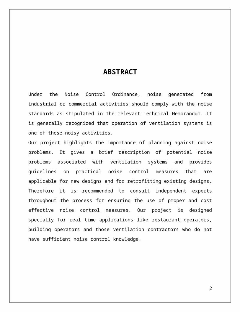
ABSTRACT
Under the Noise Control Ordinance, noise generated from industrial or commercial activities
should comply with the noise standards as stipulated in the relevant Technical Memorandum. It
is generally recognized that operation of ventilation systems is one of these noisy activities.
Our project highlights the importance of planning against noise problems. It gives a brief
description of potential noise problems associated with ventilation systems and provides
guidelines on practical noise control measures that are applicable for new designs and for
retrofitting existing designs. Therefore it is recommended to consult independent experts
throughout the process for ensuring the use of proper and cost effective noise control measures.
Our project is designed specially for real time applications like restaurant operators, building
operators and those ventilation contractors who do not have sufficient noise control knowledge.
2
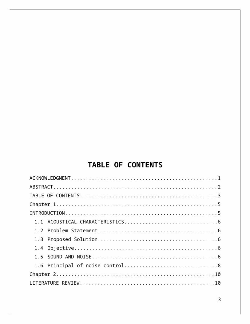
TABLE OF CONTENTSACKNOWLEDGMENT.................................................................................................................1ABSTRACT....................................................................................................................................2TABLE OF CONTENTS................................................................................................................3Chapter 1..........................................................................................................................................5INTRODUCTION...........................................................................................................................5
1.1 ACOUSTICAL CHARACTERISTICS............................................................................61.2 Problem Statement............................................................................................................61.3 Proposed Solution.............................................................................................................61.4 Objective...........................................................................................................................61.5 SOUND AND NOISE......................................................................................................61.6 Principal of noise control..................................................................................................8
Chapter 2........................................................................................................................................10LITERATURE REVIEW..............................................................................................................10
2.1 Acoustics.........................................................................................................................102.2 Noise Control Mechanism..............................................................................................122.3 Acoustics/Filter Design and Implementation..................................................................13
Design....................................................................................................................................182.4 Temperature....................................................................................................................18
Chapter 3........................................................................................................................................21PROJECT DESIGN AND IMPLEMENTATION........................................................................21
3.1 Block Diagram................................................................................................................213.2 Methodology...................................................................................................................223.3 Circuit Design.................................................................................................................22
Chapter 4........................................................................................................................................25TOOLS AND TECHNIQUES.......................................................................................................25
4.1 Arduino Uno...................................................................................................................25Reset Button.........................................................................................................................28Power LED Indicator..........................................................................................................28TX RX LEDs........................................................................................................................29Main IC.................................................................................................................................29Voltage Regulator................................................................................................................29
4.2 Air Ducts.........................................................................................................................314.3 Resistor............................................................................................................................35
3
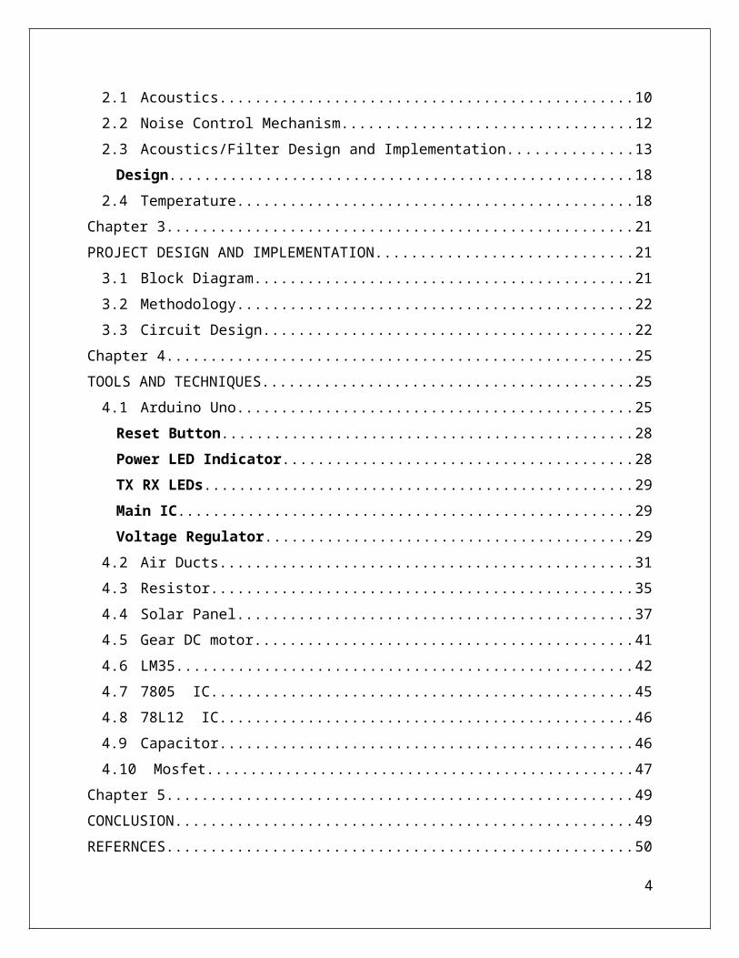
4.4 Solar Panel......................................................................................................................374.5 Gear DC motor................................................................................................................414.6 LM35...............................................................................................................................424.7 7805 IC...........................................................................................................................454.8 78L12 IC........................................................................................................................464.9 Capacitor.........................................................................................................................464.10 Mosfet..........................................................................................................................47
Chapter 5........................................................................................................................................49CONCLUSION..............................................................................................................................49REFERNCES.................................................................................................................................50
4

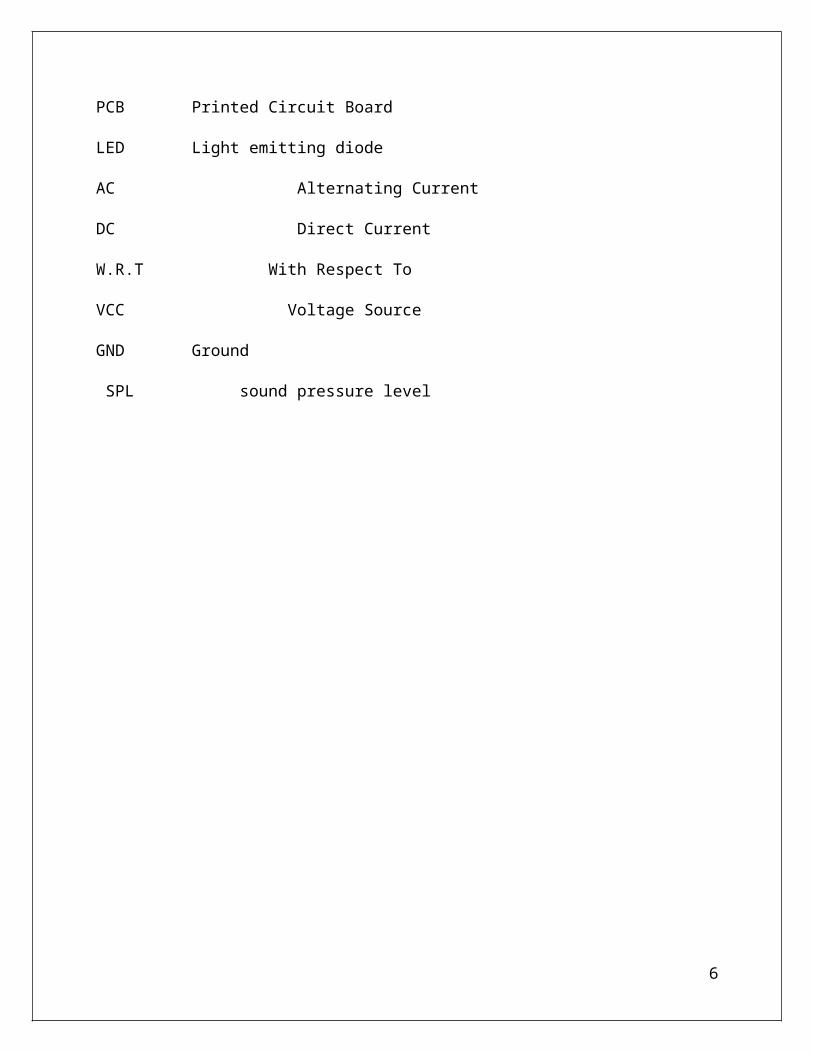
LIST OF ACRONYMS
IC Integrated Circuit
PCB Printed Circuit Board
LED Light emitting diode
AC Alternating Current
DC Direct Current
W.R.T With Respect To
VCC Voltage Source
GND Ground
SPL sound pressure level
5
Chapter 1
INTRODUCTION
1.1 ACOUSTICAL CHARACTERISTICS
There are several acoustical characteristics that occupants typically notice when entering a space.
The first is often background noise, that is how loud or quiet a space is. Another is how
reverberant a space is. When there are surrounding occupied spaces, the noise isolation (or lack
thereof) provided by building assemblies can become apparent.
1.2 Problem StatementAs now a days Solar panels are most frequently used, but unfortunately there are is a very little
work done on dc fans and coolers and having no filters with such systems. That’s why we came
up with an idea to design our own prototype model. With filters and acoustic noise reduction
system. in our project we will design dc cooler system instead of ac. As ac coolers are already
there in market.
1.3 Proposed SolutionIn the conventional systems the ducting for the AC cooling plants/ room coolers is done in such
a way, that in room the ducts opening remain open all the time due to which the noise
continuously enters in room through those ducts. this problem can be solved if we make some
mechanical adjustments along with the noise reduction filters. We will make a filter to eliminate
the electrical noise generated in dc motor during the power mode operation. So will solve the
acoustic noise and electrical noise by the use of mechanical and electrical filter.
6
1.4 ObjectiveThe main objective of this project is to design such a system that will minimize the noise with
acoustic and electrical. Plus the desired system will also be capable of the automatic speed
control of the dc fan depending on the temperature.
1.5 SOUND AND NOISESound waves in air result from a physical disturbance of air molecules, such as when a truck
drives by a building or when guitar strings are plucked. Sound waves combine and reach a
listener via numerous direct and indirect pathways. The listener’s inner ear contains organs that
vibrate in response to these molecular disturbances, converting the vibrations into changing
electrical potentials that are sensed by the brain, allowing hearing to occur.
Acoustical analysis involves not only the sound source but also the listener and everything in
between on the path of the sound. The perception of the receiver can be influenced by the
treatment of either the path or the source. Some source sound is desirable, for example a
lecturer’s voice, and some source sound is undesirable, such as the sound output from an idling
truck outside a window. Undesirable sound is usually called noise. Unless it is a pure tone, a
sound wave is typically made up of vibrations at different frequencies. Like the impact of a stone
in a lake, ripples in the water are created that are analogous to sound in the air. The frequency is
basically the number of waves that pass a single point in one second, moving at the speed of
sound in air. One wave per second is a frequency of one hertz (Hz). A frequency of 1,000 hertz is
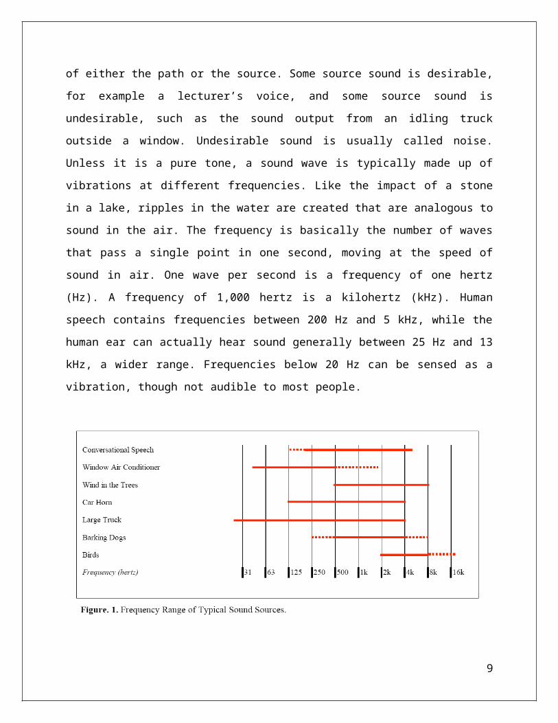
a kilohertz (kHz). Human speech contains frequencies between 200 Hz and 5 kHz, while the
human ear can actually hear sound generally between 25 Hz and 13 kHz, a wider range.
Frequencies below 20 Hz can be sensed as a vibration, though not audible to most people.
7
Sound and noise are described using a metric called the decibel. The decibel scale is logarithmic,
similar to the Richter scale used to describe seismic events, and translates a wide range of sound
pressure levels that affect the human ear to a logarithmic scale. The range of decibels most
commonly encountered in acoustics extends from 0 to 140 dB. correlates the sound pressure
levels of common sound sources to the logarithmic decibel scale.
1.6 Principal of noise controlThere are three basic elements in any noise control system, as illustrated in
1. The source of the sound
2. The path through which the sound travels
3. The receiver of the sound
In many situations, of course, there are several sources of sound, various paths for the sound, and
more than one receiver, but the basic principles of noise control would be the same as for the
more simple case. The objective of most noise control programs is to reduce the noise at the
receiver. This may be accomplished by making modifications to the source, the path, or the
receiver, or to any combination of these elements. The source of noise or undesirable sound is a
vibrating surface, such as a panel in an item of machinery, or small eddies with fluctuating
velocities in a fluid stream, such as the eddies in a jet stream leaving an air vent pipe. The path
for the sound may be the air between the source and receiver, as is the case for machinery noise
8
transmitted directly to the operator’s ears. The path may also be indirect, such as sound being
reflected by a wall to a person in the room. Solid surfaces, such as piping between a vibrating
pump and another machine element, may also serve as the path for the noise propagation. It is
important that the acoustic engineer identify all possible acoustic paths when considering a
solution for a noise problem.
9
10
Chapter 2
LITERATURE REVIEW
2.1 AcousticsAcoustics is the interdisciplinary science that deals with the study of all mechanical waves in
gases, liquids, and solids including topics such as vibration, sound, ultrasound and infrasound. A
scientist who works in the field of acoustics is an acoustician while someone working in the field
of acoustics technology may be called an acoustical engineer. The application of acoustics is
present in almost all aspects of modern society with the most obvious being the audio and noise
control industries.
Hearing is one of the most crucial means of survival in the animal world, and speech is one of
the most distinctive characteristics of human development and culture. Accordingly, the science
of acoustics spreads across many facets of human society music, medicine, architecture,
industrial production, warfare and more. Likewise, animal species such as songbirds and frogs
use sound and hearing as a key element of mating rituals or marking territories. Art, craft,
science and technology have provoked one another to advance the whole, as in many other fields
of knowledge. Robert Bruce Lindsay's 'Wheel of Acoustics' is a well accepted overview of the
various fields in acoustics.
The word "acoustic" is derived from the Greek word ἀκουστικός (akoustikos), meaning "of or
for hearing, ready to hear" and that from ἀκουστός (akoustos), "heard, audible", which in turn
derives from the verb ἀκούω (akouo), "I hear".
The Latin synonym is "sonic", after which the term sonics used to be a synonym for acoustics
and later a branch of acoustics. Frequencies above and below the audible range are called
"ultrasonic" and "infrasonic", respectively.
11

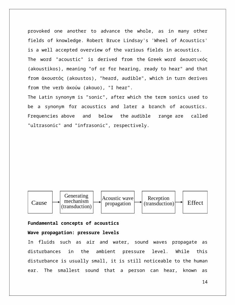
Fundamental concepts of acoustics
Wave propagation: pressure levels
In fluids such as air and water, sound waves propagate as disturbances in the ambient pressure
level. While this disturbance is usually small, it is still noticeable to the human ear. The smallest
sound that a person can hear, known as the threshold of hearing, is nine orders of magnitude
smaller than the ambient pressure. The loudness of these disturbances is called the sound
pressure level (SPL), and is measured on a logarithmic scale in decibels.
Wave propagation: frequency
Physicists and acoustic engineers tend to discuss sound pressure levels in terms of frequencies,
partly because this is how our earsinterpret sound. What we experience as "higher pitched" or
"lower pitched" sounds are pressure vibrations having a higher or lower number of cycles per
second. In a common technique of acoustic measurement, acoustic signals are sampled in time,
and then presented in more meaningful forms such as octave bands or time frequency plots. Both
of these popular methods are used to analyze sound and better understand the acoustic
phenomenon.
The entire spectrum can be divided into three sections: audio, ultrasonic, and infrasonic. The
audio range falls between 20 Hz and 20,000 Hz. This range is important because its frequencies
can be detected by the human ear. This range has a number of applications, including speech
communication and music. The ultrasonic range refers to the very high frequencies: 20,000 Hz
and higher. This range has shorter wavelengths which allow better resolution in imaging
technologies. Medical applications such as ultrasonography and elastography rely on the
ultrasonic frequency range. On the other end of the spectrum, the lowest frequencies are known
as the infrasonic range. These frequencies can be used to study geological phenomena such as
earthquakes.
Analytic instruments such as the spectrum analyzer facilitate visualization and measurement of
acoustic signals and their properties. The spectrogram produced by such an instrument is a
12
graphical display of the time varying pressure level and frequency profiles which give a specific
acoustic signal its defining character.
Transduction in acoustics
A transducer is a device for converting one form of energy into another. In an electroacoustic
context, this means converting sound energy into electrical energy (or vice versa).
Electroacoustic transducers
include loudspeakers, microphones, hydrophones and sonar projectors. These devices convert a
sound pressure wave to or from an electric signal. The most widely used transduction principles
areelectromagnetism, electrostatics and piezoelectricity.
The transducers in most common loudspeakers (e.g. woofers and tweeters), are electromagnetic
devices that generate waves using a suspended diaphragm driven by an electromagnetic voice
coil, sending off pressure waves. Electret microphones and condenser microphones employ
electrostatics—as the sound wave strikes the microphone's diaphragm, it moves and induces a
voltage change. The ultrasonic systems used in medical ultrasonography employ piezoelectric
transducers. These are made from special ceramics in which mechanical vibrations and electrical
fields are interlinked through a property of the material itself.
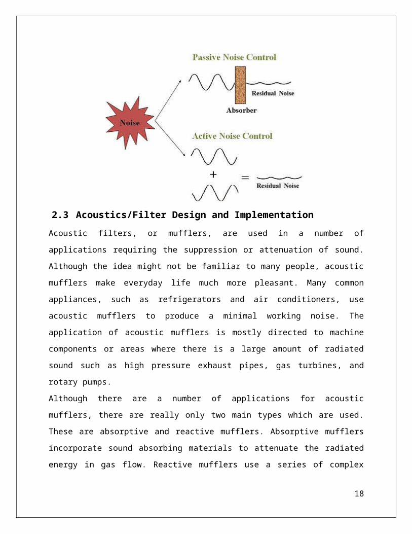
2.2 Noise Control MechanismActive Noise control
Modifying and canceling sound field by electro-acoustical approaches is called active noise
control. There are two methods for active control. First by utilizing the actuators as an acoustic
source to produce completely out of phase signals to eliminate the disturbances. second method
is to use flexible and vibro-elastic materials to radiate a sound field interfering with the
disturbances and minimize the overall intensity. The latter method is called active structural
acoustic control (ASAC).
Passive Noise Control
Passive noise control refers to those methods that aim to suppress the sound by modifying the
environment close to the source. Since no input power is required in such methods, Passive noise
control is often cheaper than active control, however the performance is limited to mid and high
13
frequencies. active control works well for low frequencies hence, the combination of two
methods may be utilized for broadband noise reduction.
2.3 Acoustics/Filter Design and ImplementationAcoustic filters, or mufflers, are used in a number of applications requiring the suppression or
attenuation of sound. Although the idea might not be familiar to many people, acoustic mufflers
make everyday life much more pleasant. Many common appliances, such as refrigerators and air
conditioners, use acoustic mufflers to produce a minimal working noise. The application of
acoustic mufflers is mostly directed to machine components or areas where there is a large
amount of radiated sound such as high pressure exhaust pipes, gas turbines, and rotary pumps.
Although there are a number of applications for acoustic mufflers, there are really only two main
types which are used. These are absorptive and reactive mufflers. Absorptive mufflers
incorporate sound absorbing materials to attenuate the radiated energy in gas flow. Reactive
mufflers use a series of complex passages to maximize sound attenuation while meeting set
specifications, such as pressure drop, volume flow, etc. Many of the more complex mufflers
today incorporate both methods to optimize sound attenuation and provide realistic
specifications.
Basic filter design
For simple filters, a long wavelength approximation can be made to make the analysis of the
system easier. When this assumption is valid (e.g. low frequencies) the components of the
14

system behave as lumped acoustical elements. Equations relating the various properties are
easily derived under these circumstances.
The following derivations assume long wavelength. Practical applications for most conditions
are given later.
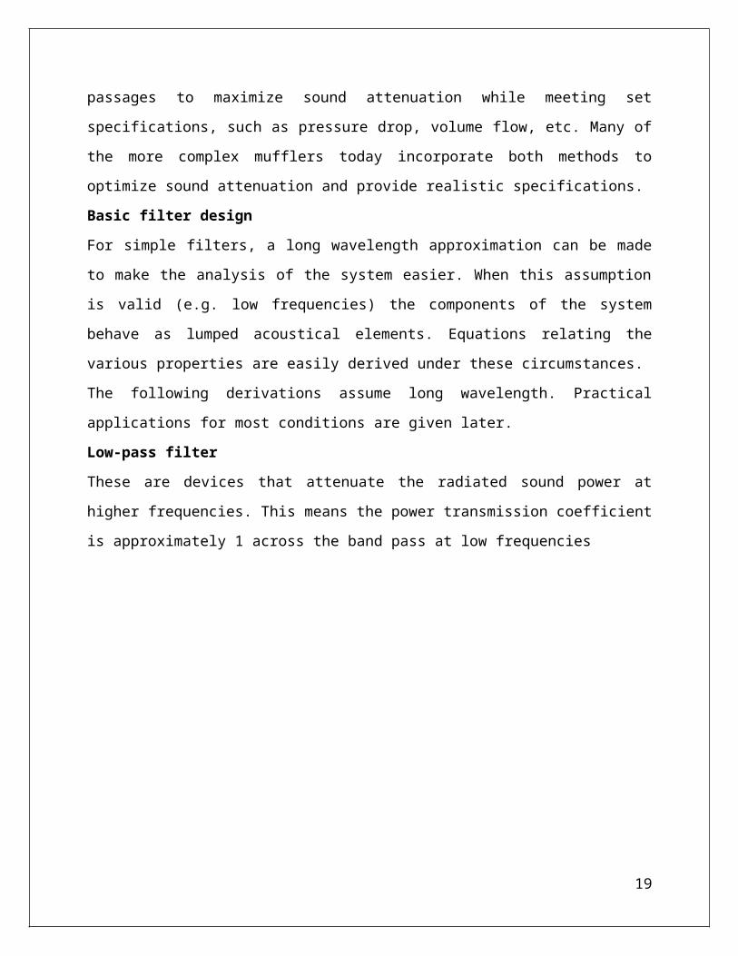
Low-pass filter
These are devices that attenuate the radiated sound power at higher frequencies. This means the
power transmission coefficient is approximately 1 across the band pass at low frequencies
where k is the wavenumber , L & are length and area of expansion respectively, and S is the
area of the pipe.
The cut-off frequency is given by:
15

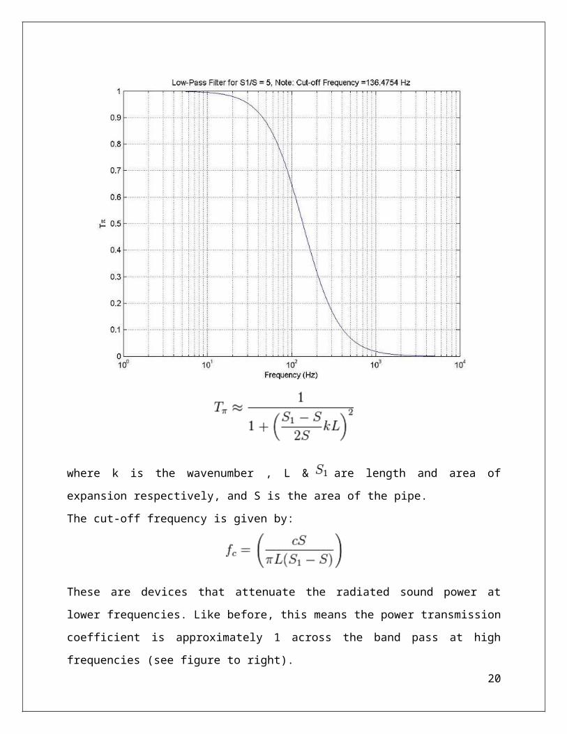
These are devices that attenuate the radiated sound power at lower frequencies. Like before, this
means the power transmission coefficient is approximately 1 across the band pass at high
frequencies (see figure to right).
High-pass filter
This is equivalent to a short side branch (see figure to right) with a radius and length much
smaller than the wavelength (lumped element assumption). This side branch acts like an acoustic
mass and applies a different acoustic impedance to the system than the low-pass filter. Again
using continuity of acoustic impedance at the junction yields a power transmission coefficient of
the form :
16
where a and L are the area and effective length of the small tube, and S is the area of the pipe.
The cut-off frequency is given by:
Band-stop filter
These are devices that attenuate the radiated sound power over a certain frequency range (see
figure to right). Like before, the power transmission coefficient is approximately 1 in the band
pass region.
Since the band-stop filter is essentially a cross between a low and high pass filter, one might
expect to create one by using a combination of both techniques. This is true in that the
combination of a lumped acoustic mass and compliance gives a band-stop filter. This can be
realized as a helmholtz resonator (see figure to right). Again, since the impedance of the
helmholtz resonator can be easily determined, continuity of acoustic impedance at the junction
can give the power transmission coefficient as:
These are devices that attenuate the radiated sound power over a certain frequency range (see
figure to right). Like before, the power transmission coefficient is approximately 1 in the band
pass region.
Since the band-stop filter is essentially a cross between a low and high pass filter, one might
expect to create one by using a combination of both techniques. This is true in that the
combination of a lumped acoustic mass and compliance gives a band-stop filter. This can be
realized as a helmholtz resonator (see figure to right). Again, since the impedance of the
helmholtz resonator can be easily determined, continuity of acoustic impedance at the junction
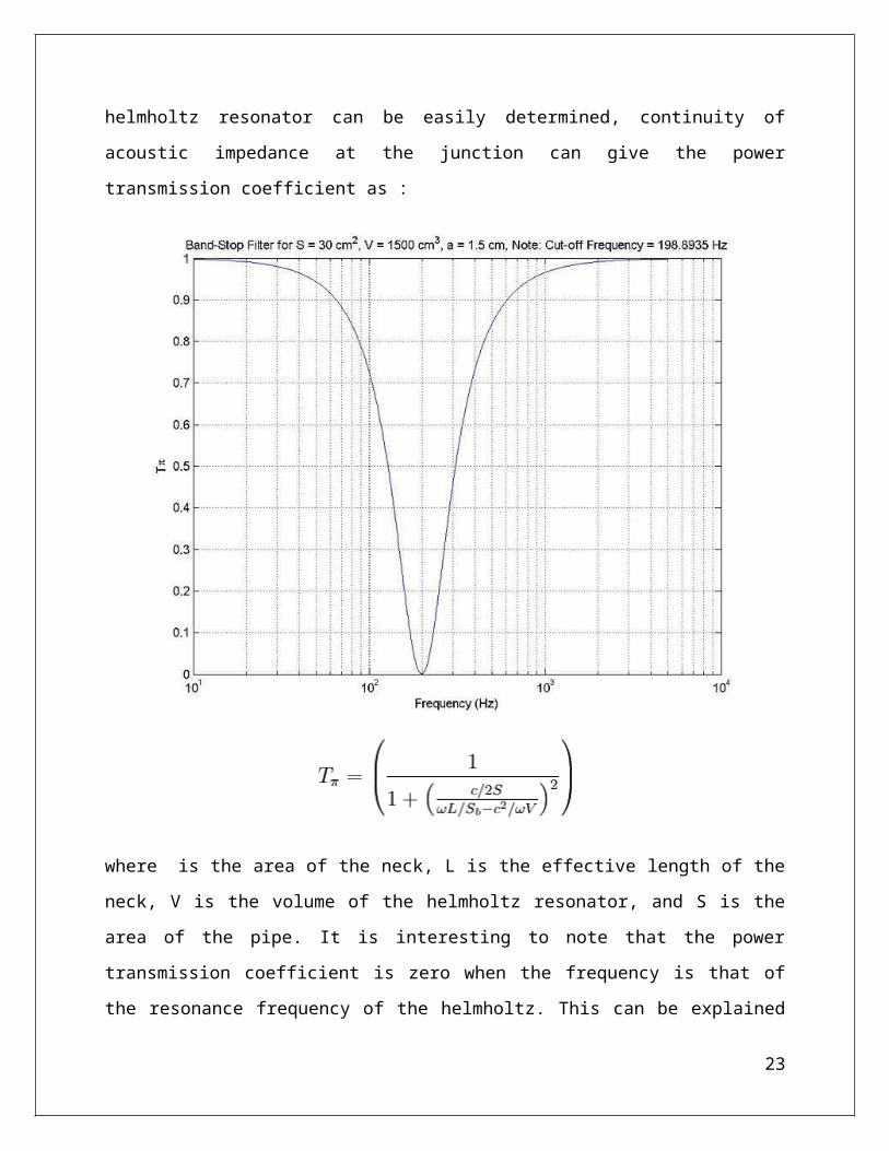
can give the power transmission coefficient as :
17
where is the area of the neck, L is the effective length of the neck, V is the volume of the
helmholtz resonator, and S is the area of the pipe. It is interesting to note that the power
transmission coefficient is zero when the frequency is that of the resonance frequency of the
helmholtz. This can be explained by the fact that at resonance the volume velocity in the neck is
large with a phase such that all the incident wave is reflected back to the source .
The zero power transmission coefficient location is given by
18
Design
If the long wavelength assumption is valid, typically a combination of methods described above
are used to design a filter. A specific design procedure is outlined for a helmholtz resonator, and
other basic filters follow a similar procedure .
Two main metrics need to be identified when designing a helmholtz resonator :
1. Resonance frequency desired: where .
2. - Transmission loss: based on TL level. This constant is found from a
TL graph (see HR pp. 6).
This will result in two equations with two unknowns which can be solved for the unknown
dimensions of the helmholtz resonator. It is important to note that flow velocities degrade the
amount of transmission loss at resonance and tend to move the resonance location upwards.
In many situations, the long wavelength approximation is not valid and alternative methods must
be examined. These are much more mathematically rigorous and require a complete
understanding acoustics involved.
2.4 TemperatureThe prediction of the temperature distribution inside an operating electric motor is one of the
most important issues during its design. This prediction allows the engineer to evaluate if the
machine will reach the thermal class for which it is being designed, establishing the bearing
lubrication intervals as well as checking if the supplied air flow of the cooling system is
sufficient for ensuring normal motor operation at rated conditions.
It provides a means to estimate the impact voltage/frequency variation have on the winding
insulation life once the temperature change is determined. for every 10°C increase in winding
temperature, the expected thermal life of the winding is reduced by half. There may also be a
notable decrease in bearing lubricant life as operating temperature of the motor increases.
19
The main mechanisms of heat generation in induction electric motors are generally divided in
four groups, related mainly to the places where they occur. These are Joule losses, iron losses,
stray load losses and mechanical losses. Each
one of these kinds of energy conversion from electric to thermal energy is detailed below.
Joule Losses
This mechanism corresponds to the conversion of electric energy into thermal energy in
electrical conducting media.
This type of losses is directly related to the electric resistance of the conductor and changes
proportionally to the square
of the current, i.e., Pj = R*I². Energy conversion by Joule effect in squirrel cage induction
electric motors occurs in the stator (copper windings) and in the squirrel cage (aluminum bars).
Iron Losses
These losses are due to the conversion of electric energy into thermal energy in the iron. They
are divided in hysteresis and Foucault (eddy currents) losses. The eddy-current losses are Joule
losses that occur in the iron due to the flow of an induced electric current. The hysteresis losses
are due to the energy expended to align the iron magnetic poles to the applied magnetic field and
their order of magnitude corresponds to the area of the hysteresis loop in the electrical induction
(B) versus magnetic field (H) .
Stray load losses
The stray load losses are minor losses in the electric motor operation and their quantification is
very difficult. They include the losses due to the skin effect, high frequency, among others, that
are unknown or not easily quantified.
Mechanical losses
These losses comprise the conversion of the mechanical energy into thermal energy due to
mechanical friction and viscous losses. Here are included mainly the losses in the rolling
bearings (balls/rings interface) and the cooling fan losses. The cooling fan losses are due to the
mechanical energy required for blowing air over the motor surface, including the conversion of
air kinetic energy, flow work and viscous dissipation.
Contribution of Each Group
For the correct modeling, it is important to quantify the suitable value and location of the heat
generation. In general, the quantification of the losses is directly related to the location where
20
these losses occur in the electric motor, excepting the stray losses. the distribution of these losses
and the respective locations where they occur.
21
Chapter 3
PROJECT DESIGN AND IMPLEMENTATION
3.1 Block Diagram
22
controller "atmega328"
Filter
Temperature sensorlm35
Power
air duct
Dc Cooler Solar panel
3.2 MethodologyIn this project we will make a dc operated room cooler prototype model. We will provide the voltage
from the solar panel. Then a special filter will be designed to minimize the electrical noise due to the
involvement of other frequencies and will be used with a specially designed mechanical ducting. And
a temperature control system will be developed to keep the temperature constant.
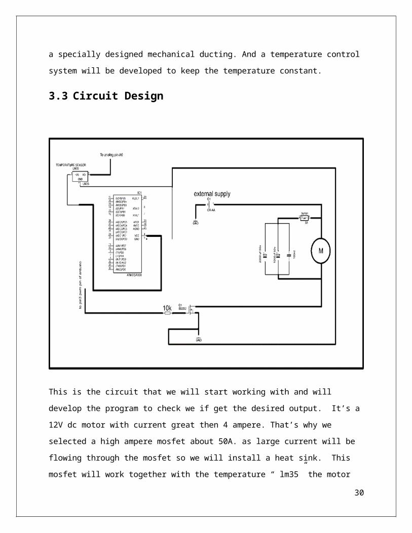
3.3 Circuit Design
This is the circuit that we will start working with and will develop the program to check we if get the
desired output. It’s a 12V dc motor with current great then 4 ampere. That’s why we selected a high
ampere mosfet about 50A. as large current will be flowing through the mosfet so we will install a
heat sink. This mosfet will work together with the temperature “ lm35” the motor speed will vary
according the temperature . The Motor will be provided with the external source.
23
Chapter 4
TOOLS AND TECHNIQUES
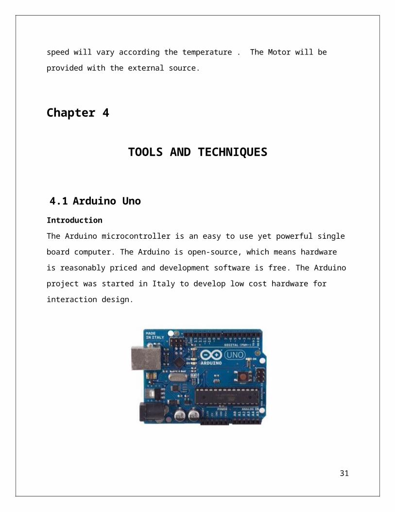
4.1 Arduino UnoIntroduction
The Arduino microcontroller is an easy to use yet powerful single board computer. The Arduino is
open-source, which means hardware is reasonably priced and development software is free. The
Arduino project was started in Italy to develop low cost hardware for interaction design.
The ATmega328 microcontroller operating at 5 V with 2 Kb of RAM, 32 Kb of flash memory for
storing programs and 1 Kb of EEPROM for storing
parameters. The clock speed is 16 MHz, which translates to about executing about 300,000 lines of
C source code per second. The board has 14 digital I/O pins and 6 analog input pins.There is a
USB connector for talking to the host computer and a DC power jack for connecting an external 6-
20 V power source, for example a 9 V battery, when running a program while not connected to the
24
host computer. Headers are provided for interfacing to the I/O pins using 22 solid wire or header
connectors.
The Arduino programming language is a simplified version of C/C++. If you know C,
programming the Arduino will be familiar. If you do not know C, no need to worry as only a few
commands are needed to perform useful functions.
An important feature of the Arduino is that you can create a control program on the host PC,
download it to the Arduino and it will run automatically. Remove the USB cable connection to the
PC, and the program will still run from the top each time you push the reset button. Remove the
battery and put the Arduino board in a closet for six months. When you reconnect the battery, the
last program you stored will run. This means that you connect the board to the host PC to develop
and debug your program, but once that is done, you no longer need the PC to run the program.
What Does it Do?
The Arduino hardware and software was designed for artists, designers, hobbyists, hackers,
newbies, and anyone interested in creating interactive objects or environments. Arduino can
interact with buttons, LEDs, motors, speakers, GPS units, cameras, the internet, and even your
smart-phone or your TV! This flexibility combined with the fact that the Arduino software is free,
the hardware boards are pretty cheap, and both the software and hardware are easy to learn has led
to a large community of users who have contributed code and released instructions for
a huge variety of Arduino-based projects.
For everything from robots and a heating pad hand warming blanket to honest fortune-telling
machines, and even aDungeons and Dragons dice-throwing gauntlet, the Arduino can be used as
the brains behind almost any electronics project
What's on the board?
There are many varieties of Arduino boards (explained on the next page) that can be used for
different purposes. Some boards look a bit different from the one below, but most Arduinos have
the majority of these components in common:
25
Power (USB / Barrel Jack)
Every Arduino board needs a way to be connected to a power source. The Arduino UNO can be
powered from a USB cable coming from your computer or a wall power supply (like this) that is
terminated in a barrel jack. In the picture above the USB connection is labeled (1) and the barrel
jack is labeled (2).
The USB connection is also how you will load code onto your Arduino board. More on how to
program with Arduino can be found in our Installing and Programming Arduino tutorial.
NOTE: Do NOT use a power supply greater than 20 Volts as you will overpower (and thereby
destroy) your Arduino. The recommended voltage for most Arduino models is between 6 and 12
Volts.
Pins (5V, 3.3V, GND, Analog, Digital, PWM, AREF)
The pins on your Arduino are the places where you connect wires to construct a circuit (probably
in conjuction with abreadboard and some wire. They usually have black plastic ‘headers’ that
26
allow you to just plug a wire right into the board. The Arduino has several different kinds of pins,
each of which is labeled on the board and used for different functions.
GND (3): Short for ‘Ground’. There are several GND pins on the Arduino, any of which
can be used to ground your circuit.
5V (4) & 3.3V (5): As you might guess, the 5V pin supplies 5 volts of power, and the
3.3V pin supplies 3.3 volts of power. Most of the simple components used with the
Arduino run happily off of 5 or 3.3 volts.
Analog (6): The area of pins under the ‘Analog In’ label (A0 through A5 on the UNO)
are Analog In pins. These pins can read the signal from an analog sensor (like
a temperature sensor) and convert it into a digital value that we can read.
Digital (7): Across from the analog pins are the digital pins (0 through 13 on the UNO).
These pins can be used for both digital input (like telling if a button is pushed) and digital
output (like powering an LED).
PWM (8): You may have noticed the tilde (~) next to some of the digital pins (3, 5, 6, 9,
10, and 11 on the UNO). These pins act as normal digital pins, but can also be used for
something called Pulse-Width Modulation (PWM).
AREF (9): Stands for Analog Reference. Most of the time you can leave this pin alone.
It is sometimes used to set an external reference voltage (between 0 and 5 Volts) as the
upper limit for the analog input pins.
Reset Button
Just like the original Nintendo, the Arduino has a reset button (10). Pushing it will temporarily
connect the reset pin to ground and restart any code that is loaded on the Arduino. This can be
very useful if your code doesn’t repeat, but you want to test it multiple times. Unlike the original
Nintendo however, blowing on the Arduino doesn’t usually fix any problems.
Power LED Indicator
Just beneath and to the right of the word “UNO” on your circuit board, there’s a tiny LED next to
the word ‘ON’ (11). This LED should light up whenever you plug your Arduino into a power
source. If this light doesn’t turn on, there’s a good chance something is wrong. Time to re-check
your circuit!
27

TX RX LEDs
TX is short for transmit, RX is short for receive. These markings appear quite a bit in electronics
to indicate the pins responsible for serial communication. In our case, there are two places on the
Arduino UNO where TX and RX appear – once by digital pins 0 and 1, and a second time next
to the TX and RX indicator LEDs (12). These LEDs will give us some nice visual indications
whenever our Arduino is receiving or transmitting data (like when we’re loading a new program
onto the board).
Main IC
The black thing with all the metal legs is an IC, or Integrated Circuit (13). Think of it as the
brains of our Arduino. The main IC on the Arduino is slightly different from board type to board
type, but is usually from the ATmega line of IC’s from the ATMEL company. This can be
important, as you may need to know the IC type (along with your board type) before loading up
a new program from the Arduino software. This information can usually be found in writing on
the top side of the IC. If you want to know more about the difference between various IC’s,
reading the datasheets is often a good idea.
Voltage Regulator
The voltage regulator (14) is not actually something you can (or should) interact with on the
Arduino. But it is potentially useful to know that it is there and what it’s for. The voltage
regulator does exactly what it says – it controls the amount of voltage that is let into the Arduino
board. Think of it as a kind of gatekeeper; it will turn away an extra voltage that might harm the
circuit. Of course, it has its limits, so don’t hook up your Arduino to anything greater than 20
volts.
Installing the Software
This is the indication that you have all software and drivers successfully
installed and can start exploring with your own programs.
28
Troubleshooting
If there is a syntax error in the program caused by a mistake in typing, an error message will appear
in the bottom of the program window. Generally, staring at the error will reveal the problem. If you
continue to have problems, try these ideas
Run the Arduino program again
Check that the USB cable is secure at both ends.
Reboot your PC because sometimes the serial
Solderless Breadboards
A solderless breadboard is an essential tool for rapidly prototyping electronic circuits.
Components and wire push into breadboard holes. Rows and columns of holes are internally
connected to make connections easy. Wires run from the breadboard to the I/O pins on the Arduino
board. Make connections using short lengths of 22 g solid wire stripped of insulation about 0.25” at
each end. The pairs of horizontal runs at the top and bottom are useful for running power and
ground. Convention is to make the red colored run +5 V and the blue colored run Gnd. The power
runs are sometimes called “power busses”.
Flashing an LED
Light emitting diodes (LED's) are handy for checking out Arduino .For this task, we need an LED,
a 330 ohm resistor, and some short pieces of 22 or 24 g wire.Using 22 g solid wire, connect the 5V
power pin on the Arduino to the bottom red power bus on the breadboard and the Gnd pin on the
Arduino to the bottom blue power buss.
Arduino Hardware
The power of the Arduino is not its ability to crunch code, but rather its ability to interact with the
outside world through its input-output (I/O) pins. The Arduino has 14 digital I/O pins labeled 0 to
13 that can be used to turn motors and lights on and off and read the state of switches.Each digital
pin can sink or source about 40 mA of current. This is more than adequate for interfacing to most
devices, but does mean that interface circuits are needed to control devices other than simple
LED's. In other words, you cannot run a motor directly using the current available from an Arduino
pin, but rather must have the pin drive an interface circuit that in turn drives the motor.
29
A later section of this document shows how to interface to a small motor.To interact with the
outside world, the program sets digital pins to a high or low value using C code instructions, which
corresponds to +5 V or 0 V at the pin. The pin is connected to external interface electronics and
then to the device being switched on and off. The sequence of events is shown in this figure.
To determine the state of switches and other sensors, the Arduino is able to read the voltage
value applied to its pins as a binary number. The interface circuitry translates the sensor signal into
a 0 or +5 V signal applied to the digital I/O pin. Through a program command, the Ardiomp
interrogates the state of the pin. If the pin is at 0 V, the program will read it as a 0 or LOW. If it is
at +5 V, the program will read it as a 1 or HIGH. If more than +5 V is applied, you may blow out
your board, so be careful. The sequence of events to read a pin is shown in this figure.
Interacting with the world has two sides. First, the designer must create electronic interface
circuits that allow motors and other devices to be controlled by a low (1-10 mA) current signal that
switches between 0 and 5 V, and other circuits that convert sensor readings into a switched 0 or 5
V signal. Second, the designer must write a program using the set of Arduino commands that set
and read the I/O pins.
When reading inputs, pins must have either 0 or 5V applied. If a pin is left open or "floating", it
will read random voltages and cause erratic results. This is why switches always have a 10K pull
up resistor connected when interfacing to an Arduino pin.The Arduino also has six analog input
pins for reading continuous voltages in the range of 0 to 5 V from sensors such as potentiometers
Programming Concepts
A computer program is a sequence of step-by-step instructions for the computer to follow. The
computer will do exactly what you tell it to do, no more no less. The computer only knows what's
in the program, not what you intended. Thus the origin of the phrase, "Garbage in, garbage out".
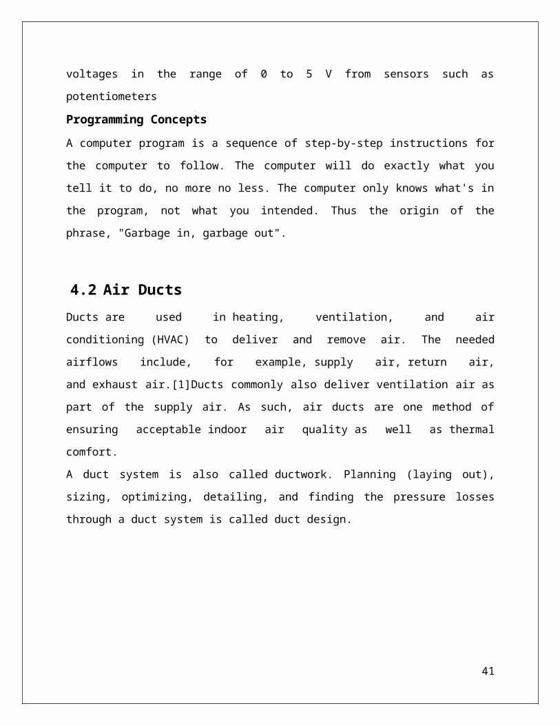
4.2 Air DuctsDucts are used in heating, ventilation, and air conditioning (HVAC) to deliver and remove air. The
needed airflows include, for example, supply air, return air, and exhaust air.[1]Ducts commonly
also deliver ventilation air as part of the supply air. As such, air ducts are one method of ensuring
acceptable indoor air quality as well as thermal comfort.
30
A duct system is also called ductwork. Planning (laying out), sizing, optimizing, detailing, and
finding the pressure losses through a duct system is called duct design.
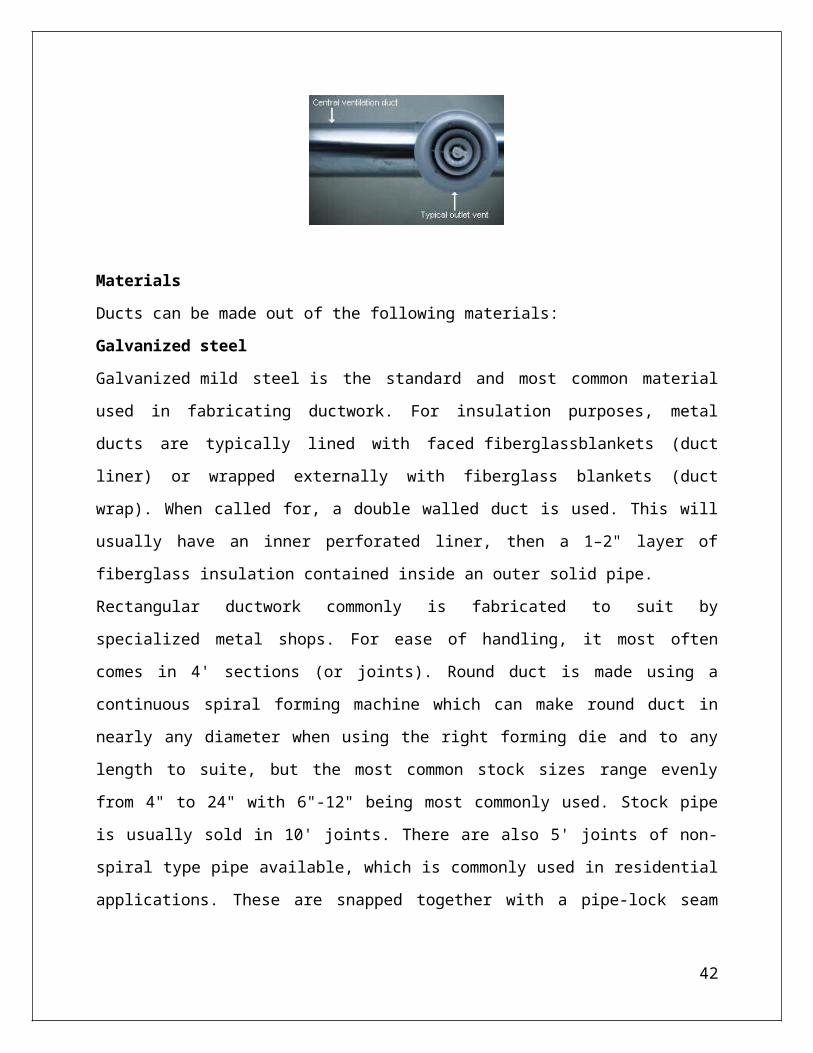
Materials
Ducts can be made out of the following materials:
Galvanized steel
Galvanized mild steel is the standard and most common material used in fabricating ductwork. For
insulation purposes, metal ducts are typically lined with faced fiberglassblankets (duct liner) or
wrapped externally with fiberglass blankets (duct wrap). When called for, a double walled duct is
used. This will usually have an inner perforated liner, then a 1–2" layer of fiberglass insulation
contained inside an outer solid pipe.
Rectangular ductwork commonly is fabricated to suit by specialized metal shops. For ease of
handling, it most often comes in 4' sections (or joints). Round duct is made using a continuous
spiral forming machine which can make round duct in nearly any diameter when using the right
forming die and to any length to suite, but the most common stock sizes range evenly from 4" to
24" with 6"-12" being most commonly used. Stock pipe is usually sold in 10' joints. There are also
5' joints of non-spiral type pipe available, which is commonly used in residential applications.
These are snapped together with a pipe-lock seam and uses a crimped and beaded small end (the
outlet of the direction of airflow) for connections.
Aluminium
Aluminium ductwork is lightweight and quick to install. Also, custom or special shapes of ducts
can be easily fabricated in the shop or on site.
The ductwork construction starts with the tracing of the duct outline onto the aluminium
preinsulated panel. The parts are then typically cut at 45°, bent if required to obtain the different
31

fittings (i.e. elbows, tapers) and finally assembled with glue. Aluminium tape is applied to all
seams where the external surface of the aluminium foil has been cut. A variety of flanges are
available to suit various installation requirements. All internal joints are sealed with sealant.
Aluminum is also used to make round spiral duct, but it is much less common than galvanized
steel.
Polyurethane and phenolic insulation panels (pre-insulated air ducts)
Traditionally, air ductwork is made of sheet metal which was installed first and then lagged with
insulation. Today, a sheet metal fabrication shop would commonly fabricate the galvanized steel
duct and insulate with duct wrap prior to installation. However, ductwork manufactured from rigid
insulation panels does not need any further insulation and can be installed in a single step.
Both polyurethane and phenolic foam panels are manufactured with factory applied aluminium
facings on both sides. The thickness of the aluminium foil can vary from 25 micrometres for
indoor use to 200 micrometres for external use or for higher mechanical characteristics. There are
various types of rigid polyurethane foam panels available, including a water formulated panel for
which the foaming process is obtained through the use of water and CO2 instead
of CFC, HCFC, HFC and HC gasses. Most manufacturers of rigid polyurethane or phenolic foam
panels use pentane as foaming agent instead of the aforementioned gasses.
A rigid phenolic insulation ductwork system is listed as a class 1 air duct to UL 181 Standard for
Safety.
Fiberglass duct board (preinsulated non-metallic ductwork)
Fiberglass duct board panels provide built-in thermal insulation and the interior surface
absorbs sound, helping to provide quiet operation of the HVAC system.
The duct board is formed by sliding a specially-designed knife along the board using a straightedge
as a guide. The knife automatically trims out a groove with 45° sides which does not quite
penetrate the entire depth of the duct board, thus providing a thin section acting as a hinge. The
duct board can then be folded along the groove to produce 90° folds, making the rectangular duct
shape in the fabricator's desired size. The duct is then closed with outward-clinching staples and
special aluminum or similar metal-backed tape.
Flexible ducting
Flexible ducts (also known as flex) are typically made of flexible plastic over a metal wire coil to
shape a tube. They have a variety of configurations. In the United States, the insulation is
32

usually glass wool, but other markets such as Australia, use both polyester fibre and glass wool for
thermal insulation. A protective layer surrounds the insulation, and is usually composed
of polyethylene or metalised PET. It is commonly sold boxes containing 25' of duct compressed
into a 5' length. It is available in diameters ranging from as small as 4" to as big as 18", but the
most commonly used are even sizes ranging from 6" to 12".
Flexible duct is very convenient for attaching supply air outlets to the rigid ductwork. It is
commonly attached with long zip ties or metal band claps. However, the pressure loss is higher
than for most other types of ducts. As such, designers and installers attempt to keep their installed
lengths (runs) short, e.g. less than 15 feet or so, and try to minimize turns. Kinks in flexible ducting
must be avoided. Some flexible duct markets prefer to avoid using flexible duct on the return air
portions of HVAC systems, however flexible duct can tolerate moderate negative pressures. The
UL181 test requires a negative pressure of 200 Pa.
Fabric ducting
This is actually an air distribution device and is not intended as a conduit for conditioned air. The
term fabric duct is therefore somehow misleading; fabric air dispersion systemwould be the more
definitive name. However, as it often replaces hard ductwork, it is easy to perceive it simply as a
duct. Usually made of polyester material, fabric ducts can provide a more even distribution and
blending of the conditioned air in a given space than a conventional duct system. They may also be
manufactured with vents or orifices.
Fabric ducts are available in various colours, with options for silk screening or other forms of
decoration, or in porous (air-permeable) and non-porous fabric. The determination which fabric is
appropriate (i.e. air-permeable or not) can be made by considering if the application would require
an insulated metal duct. If so, an air-permeable fabric is recommended because it will not
commonly create condensation on its surface and can therefore be used where air is supplied below
the dew point. Material that eliminates moisture may be healthier for the occupants. It can also be
treated with an anti-microbial agent to inhibit bacterial growth. Porous material also tends to
require less maintenance as it repels dust and other airborne contaminants.
Fabric made of more than 50% recycled material is also available, allowing it to be certified as
green product. The material can also be fire retardant, which means that the fabric can still burn,
but will extinguish when the heat source is removed.
33

Fabric ducts are not rated for use in ceilings or concealed attic spaces. However, products for use
in raised floor applications are available. Fabric ducting usually weighs less than other
conventional ducting and will therefore put less stress on the building's structure. The lower weight
allows for easier installation.
Waterproofing
The finish for external ductwork exposed to the weather can be sheet steel coated with aluminium
or an aluminium/zinc alloy, a multilayer laminate, a fibre reinforced polymer or other waterproof
coating.
4.3 ResistorIn an electronic circuit, the basic function of a resistor is to limit the current to a safe value so
that the associated sophisticated parts can function properly. Resistors come under passive
electronic components and are extensively used in electronic circuits. So important are these
components that it may be virtually impossible to build an electronic circuit without involving
resistors. Basically the function of a resistor is always to oppose the flow of current through it
and the strength of this opposition is termed as its resistance. German physicist, Sir G.S.
Ohms was able to discover a definite relationship between voltage, current and resistance.
According to him a potential difference or a voltage (V) across a resistor (R) is proportional to
the instantaneous current (I) flowing through it and is given as:
V = IR
Here R is the constant of proportionality and is known as the resistance of the resistor.
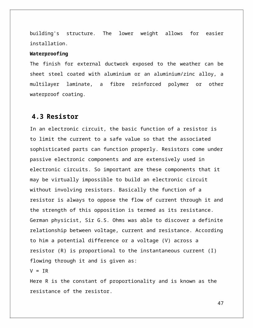
Function of Resistors in Electronics
In electronic circuits, resistors play an important role to limit the current and provide only the
required biasing to the vital active parts like the transistors and the ICs.
34
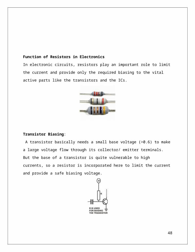
Transistor Biasing:
A transistor basically needs a small base voltage (>0.6) to make a large voltage flow through its
collector/ emitter terminals. But the base of a transistor is quite vulnerable to high currents, so a
resistor is incorporated here to limit the current and provide a safe biasing voltage.
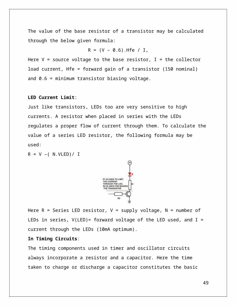
The value of the base resistor of a transistor may be calculated through the below given formula:
R = (V – 0.6).Hfe / I,
Here V = source voltage to the base resistor, I = the collector load current, Hfe = forward gain of a
transistor (150 nominal) and 0.6 = minimum transistor biasing voltage.
LED Current Limit:
Just like transistors, LEDs too are very sensitive to high currents. A resistor when placed in series
with the LEDs regulates a proper flow of current through them. To calculate the value of a series
LED resistor, the following formula may be used:
R = V –( N.VLED)/ I
35
Here R = Series LED resistor, V = supply voltage, N = number of LEDs in series, V(LED)=
forward voltage of the LED used, and I = current through the LEDs (10mA optimum).
In Timing Circuits:
The timing components used in timer and oscillator circuits always incorporate a resistor and a
capacitor. Here the time taken to charge or discharge a capacitor constitutes the basic time pulse or
trigger for the circuit. A resistor is effectively used to control this charging and discharging process
and its value is varied to obtain different time intervals.
Surge Protection:
The initial switch ON of a power supply may at times inflict a dangerous voltage surge into an
electronic circuit, damaging its critical components. A resistor when introduced in series with the
supply terminals of the circuit helps in checking the sudden rise in voltage and averting a possible
harm. These resistors are generally of low values so that the over all performance of the circuit is
not affected.
4.4 Solar PanelPhotovoltaics is the direct conversion of light into electricity at the atomic level. Some materials
exhibit a property known as the photoelectric effect that causes them to absorb photons of light and
release electrons. When these free electrons are captured, an electric current results that can be
used as electricity.
36
The photoelectric effect was first noted by a French physicist, Edmund Bequerel, in 1839, who
found that certain materials would produce small amounts of electric current when exposed to
light. In 1905, Albert Einstein described the nature of light and the photoelectric effect on which
photovoltaic technology is based, for which he later won a Nobel prize in physics. The first
photovoltaic module was built by Bell Laboratories in 1954. It was billed as a solar battery and was
mostly just a curiosity as it was too expensive to gain widespread use. In the 1960s, the space
industry began to make the first serious use of the technology to provide power aboard spacecraft.
Through the space programs, the technology advanced, its reliability was established, and the cost
began to decline. During the energy crisis in the 1970s, photovoltaic technology gained recognition
as a source of power for non-space applications.
The selection of the PV panel took into consideration the input/output power requirements of the
system as well as the available budget. In order to provide 4 hours of run time at a 50 watt draw,
the panel would have to replenish the lost energy using 8 hours of daylight. Taking into
consideration cloud shadowing, panel positioning, and inherent conversion losses, a 20 watt panel
will optimally provide ~14 watts for 8 hours leading to a deficiency of 88 watts. The reserve
capacity of the main battery is 325 watts however after a few days it would have to be taken from
the field to a charging station. This is unsatisfactory and violates the requirement that the system be
self-sustaining.
The diagram above illustrates the operation of a basic photovoltaic cell, also called a solar cell.
Solar cells are made of the same kinds of semiconductor materials, such as silicon, used in the
microelectronics industry. For solar cells, a thin semiconductor wafer is specially treated to form
an electric field, positive on one side and negative on the other. When light energy strikes the solar
37
cell, electrons are knocked loose from the atoms in the semiconductor material. If electrical
conductors are attached to the positive and negative sides, forming an electrical circuit, the
electrons can be captured in the form of an electric current -- that is, electricity. This electricity can
then be used to power a load, such as a light or a tool.
A number of solar cells electrically connected to each other and mounted in a support structure or
frame is called a photovoltaic module. Modules are designed to supply electricity at a certain
voltage, such as a common 12 volts system. The current produced is directly dependent on how
much light strikes the module.
The PV panel is a simple electrical device and given any two of three variables, the
third variable. The three variables are panel temperature, panel voltage, and output current. The
peak power current varies with solar isolation and thus using the panel output current in a maximal
power point tracking (MPPT) algorithm would require sensing solar irradiance. This can be done,
but would require mounting multiple sensors on the panel to accurately measure the irradiance
onto the panel and would unnecessarily complicate the feedback controller.
Multiple modules can be wired together to form an array. In general, the larger the area of a
module or array, the more electricity that will be produced. Photovoltaic modules and arrays
38
produce direct-current (dc) electricity. They can be connected in both series and parallel electrical
arrangements to produce any required voltage and current combination.
Today's most common PV devices use a single junction, or interface, to create an electric field
within a semiconductor such as a PV cell. In a single-junction PV cell, only photons whose energy
is equal to or greater than the band gap of the cell material can free an electron for an electric
circuit. In other words, the photovoltaic
response of single-junction cells is limited to the portion of the sun's
spectrum whose energy is above the band gap of the absorbing
material, and lower-energy photons are not used.
One way to get around this limitation is to use two (or more) different cells, with more than one
band gap and more than one junction, to generate a voltage. These are referred to as
"multijunction" cells (also called "cascade" or "tandem" cells). Multijunction devices can achieve a
higher totalconversion efficiency because they can convert more of the energy spectrum of light to
electricity.
As shown below, a multijunction device is a stack of individual single-junction cells in descending
order of band gap (Eg). The top cell captures the high-energy photons and passes the rest of the
photons on to be absorbed by lower-band-gap cells.
39

4.5 Gear DC motorA gear motor is a specific type of electrical motor that is designed to produce high torque while
maintaining a low horsepower, or low speed, motor output. Gear motors can be found in many
different applications, and are probably used in many devices in our home.
Gear motors are commonly used in devices such as can openers, garage door openers, washing
machine time control knobs and even electric alarm clocks. Common commercial applications of
a gear motor include hospital beds, commercial jacks, cranes and many other applications that
are too many to list.
Basic Principles of Operation
A gear motor can be either an AC (alternating current) or a DC (direct current) electric motor.
Most gear motors have an output of between about 1,200 to 3,600 revolutions per minute
(RPMs). These types of motors also have two different speed specifications: normal speed and
the stall-speed torque specifications.
Gear motors are primarily used to reduce speed in a series of gears, which in turn creates more
torque. This is accomplished by an integrated series of gears or a gear box being attached to the
main motor rotor and shaft via a second reduction shaft. The second shaft is then connected to
the series of gears or gearbox to create what is known as a series of reduction gears. Generally
speaking, the longer the train of reduction gears, the lower the output of the end, or final, gear
will be.
An excellent example of this principle would be an electric time clock (the type that uses hour,
minute and second hands). The synchronous AC motor that is used to power the time clock will
usually spin the rotor at around 1500 revolutions per minute. However, a series of reduction
gears is used to slow the movement of the hands on the clock.
40
For example, while the rotor spins at about 1500 revolutions per minute, the reduction gears
allow the final secondhand gear to spin at only one revolution per minute. This is what allows the
secondhand to make one complete revolution per minute on the face of the clock.
Gear Motors and Increased Force
Gear motors are commonly used in commercial applications where a piece of equipment needs to
be able to exert a high amount of force in order to move a very heavy object. Examples of these
types of equipment would include a crane or lift Jack.
If you've ever seen a crane in action, you've seen a great example of how a gear motor works. As
you have probably noticed, a crane can be used to lift and move very heavy objects. The electric
motor used in most cranes is a type of gear motor that uses the basic principles of speed
reduction to increase torque or force.
Gear motors used in cranes are usually specialty types that use a very low rotational output speed
to create incredible amounts of torque. However, the principles of the gear motor used in a crane
are exactly the same as those used in the example electric time clock. The output speed of the
rotor is reduced through a series of large gears until the rotating, RPM speed, of the final gear is
very low. The low RPM speed helps to create a high amount of force which can be used to lift
and move the heavy objects.
4.6 LM35
The LM35 - An Integrated Circuit Temperature Sensor. The LM35 series are precision
integrated-circuit temperature devices with an output voltage linearly-proportional to the
Centigrade temperature. The LM35 device has an advantage over linear temperature sensors
calibrated in Kelvin, as the user is not required to subtract a large constant voltage from the
output to obtain convenient Centigrade scaling. The LM35 device does not require any external
calibration or trimming to provide typical accuracies of ±¼°C at room temperature and ±¾°C
over a full −55°C to 150°C temperature range. Lower cost is assured by trimming and calibration
at the wafer level. The low-output impedance, linear output, and precise inherent calibration of
the LM35 device makes interfacing to readout or control circuitry especially easy. The device is
used with single power supplies, or with plus and minus supplies. As the LM35 device draws
only 60 μA from the supply, it has very low self-heating of less than 0.1°C in still air. The LM35
41
device is rated to operate over a −55°C to 150°C temperature range, while the LM35C device is
rated for a −40°C to 110°C range (−10° with improved accuracy). The LM35-series devices are
available packaged in hermetic TO transistor packages, while the LM35C, LM35CA, and
LM35D devices are available in the plastic TO-92 transistor package. The LM35D device is
available in an 8-lead surface-mount small-outline package and a plastic TO-220 package.
Uses LM35s To Measure Temperature
You can measure temperature more accurately than a using a thermistor.
The sensor circuitry is sealed and not subject to oxidation, etc.
The LM35 generates a higher output voltage than thermocouples and may not require that
the output voltage be amplified.
Working of LM35
It has an output voltage that is proportional to the Celsius temperature.
The scale factor is .01V/oC
The LM35 does not require any external calibration or trimming and maintains an
accuracy of +/-0.4 oC at room temperature and +/- 0.8 oC over a range of 0 oC to
+100 oC.
Another important characteristic of the LM35DZ is that it draws only 60 micro amps
from its supply and possesses a low self-heating capability. The sensor self-heating
causes less than 0.1 oC temperature rise in still air.
The LM35 comes in many different packages, including the following.
TO-92 plastic transistor-like package,
T0-46 metal can transistor-like package
42
8-lead surface mount SO-8 small outline package
TO-202 package. (Shown in the picture above)
In this circuit, parameter values commonly used are:
Vc = 4 to 30v
5v or 12 v are typical values used.
Ra = Vc /10-6
Actually, it can range from 80 K to 600 K , but most just use 80 K.
Here is a photo of the LM 35 wired on a circuit board.
The white wire in the photo goes to the power supply.
Both the resistor and the black wire go to ground.
The output voltage is measured from the middle pin to ground.l
Features
Calibrated Directly in Celsius (Centigrade)
Linear + 10-mV/°C Scale Factor
43

0.5°C Ensured Accuracy (at 25°C)
Rated for Full −55°C to 150°C Range
Suitable for Remote Applications
Low-Cost Due to Wafer-Level Trimming
Operates from 4 V to 30 V
Less than 60-μA Current Drain
Low Self-Heating, 0.08°C in Still Air
Non-Linearity Only ±¼°C Typical
Low-Impedance Output, 0.1 Ω for 1-mA Load
4.7 7805 IC
The 7805 ic is three terminal positive voltage regulators is available with fixed output
voltages making them useful in a wide range of applications. This regulator is inexpensive, vise-
to-use devices suitable for a multitude of applications that require a regulated supply of up to
800 mA.It includes feature of internal current limiting and thermal shutdown making them
remarkably rugged. No external components are required with the 7805 devices in many
applications.These devices offer a substantial performance advantage over the traditional
zener diode-resistor combination, as output impedance and quiescent current are
substantionally reduced.The 7805 is available in 3-Pin plastic package SOT54 (Z),offers superior
quality and performance at low cost.
4.8 78L12 IC
44

This 7812 is fixed-voltage integrated-circuit voltage regulators is designed for a wide range of
applications. These applications include on-card regulation for elimination of noise and distribution
problems associated with single-point regulation. In addition, they can be used with power-pass
elements to make high-current voltage regulators. It can deliver up to 100 mA of output current.
7812 has built in over heat and short circuit protection which makes it a good choice for making
power supplies.If we hold the ic upside down (pins up) and the IC number is facing you then the left
pin will be the voltage regulator output, the center pin will be ground and the right pin will be the
voltage input pin. Under my experience, the maximum safe current you can get from one 7812 IC is
1A.
4.9 Capacitor
A capacitor (originally known as a condenser) is a passive two-terminal electrical
component used to store electrical energytemporarily in an electric field. The forms of practical
capacitors vary widely, but all contain at least two electrical conductors (plates) separated by
a dielectric (i.e. an insulator that can store energy by becoming polarized). The conductors can be
thin films, foils or sintered beads of metal or conductive electrolyte, etc. The nonconducting
dielectric acts to increase the capacitor's charge capacity. Materials commonly used as dielectrics
include glass, ceramic, plastic film, air, vacuum, paper, mica, and oxide layers. Capacitors are
widely used as parts of electrical circuits in many common electrical devices. Unlike a resistor,
an ideal capacitor does not dissipate energy. Instead, a capacitor stores energy in the form of
an electrostatic field between its plates.
45
When there is a potential difference across the conductors (e.g., when a capacitor is attached
across a battery), an electric fielddevelops across the dielectric, causing positive charge +Q to
collect on one plate and negative charge −Q to collect on the other plate. If a battery has been
attached to a capacitor for a sufficient amount of time, no current can flow through the capacitor.
However, if a time-varying voltage is applied across the leads of the capacitor, a displacement
current can flow.
4.10 Mosfet
When utilizing N-Channel MOSFETs to switch a DC voltage across a load, the drain terminals
of the high side MOSFETs are often connected to the highest voltage in the system. This creates
a difficulty, as the gate terminal must be approximately 10V higher than the drain terminal for
the MOSFET to conduct. Often, integrated circuit devices known as MOSFET drivers are
utilized to achieve this difference through charge pumps or bootstrapping techniques. These
chips are capable of quickly charging the input capacitance of the MOSFET (Cgiss) quickly
before the potential difference is reached, causing the gate to source voltage to be the highest
46
system voltage plus the capacitor voltage, allowing it to conduct. A diagram of an N- channel
MOSFET with gate, drain, and source terminals is shown in Figure 5
There are many MOSFET drivers available to power N-Channel MOSFETs through level
translation of low voltage control signals into voltages capable of supplying sufficient gate
voltage. Advanced drivers contain circuitry for powering high and low side devices as well as N
and P-Channel MOSFETs. In this design, all MOSFETs are N-Channel due to their increased
current handling capabilities. To overcome the difficulties of driving high side N-Channel
MOSFETs, the driver devices use an external source to charge a bootstrapping capacitor
connected between Vcc and source terminals. The bootstrap capacitor provides gate charge to the
high side MOSFET. As the switch begins to conduct, the capacitor maintains a potential
difference, rapidly causing the MOSFET to further conduct, until it is fully on. The name
bootstrap component refers to this process and how the MOSFET acts as if it is “pulling itself up
by its own boot strap”.
47
Chapter 5
CONCLUSION
There are several acoustical characteristics that occupants typically notice when entering a space.
The first is often background noise, that is how loud or quiet a space is. Another is how
reverberant a space is. When there are surrounding occupied spaces, the noise isolation (or lack
thereof) provided by building assemblies can become apparent. In this project make a dc
operated room cooler prototype model. We provide the voltage from the solar panel. Then a
special filter was be designed to minimize the electrical noise due to the involvement of other
frequencies and will be used with a specially designed mechanical ducting. And a temperature
control system will be developed to keep the temperature constant. So this project is succefully
completed.
48
REFERNCEShttp://www.learningaboutelectronics.com/Articles/LM741-op-amp-comparator.php
https://en.wikipedia.org/wiki/Acoustics
https://en.wikibooks.org/wiki/Engineering_Acoustics/
Sound_Absorbing_Structures_and_Materials
https://en.wikibooks.org/wiki/Acoustics/Filter_Design_and_Implementation
https://en.wikipedia.org/wiki/Duct_(flow)
49


![STIPULATED INJUNCTION AND [PROPOSED] ORDER](https://img.pdfslide.us/doc/110x75/625c408f932478397330bca1/stipulated-injunction-and-proposed-order.jpg)


![[Proposed] Stipulated Permanent Injunction and Final Order](https://img.pdfslide.us/doc/110x75/621a6af749ab14348d4ad0d4/proposed-stipulated-permanent-injunction-and-final-order-.jpg)