Embed Size (px)
Citation preview

Table of Contents
1. Special Precautions ………………………..............................................................1
2. Terminal Function …………………………………………..………….....................1
3. Keypad &Operation ...…………………………………………….……………………,.2
4. Connection Diagrams……………..……………………………………………………..3
5. Door Run Description ………………………………………………………………….4
6. Basic procedure 1………………………………...………………...………………….6
7. Basic procedure 2……………………………………..………………………………..6
8. Function Parameter Description …………………………………..…………………..9
9. Troubleshooting ………………….………...…………………..……........................13

NSFC01-01 INSTRUCTION MANUAL
. Do not open or remove the front cover while the VariableFrequency Drive is running. You may get an electrical shock.
. When necessary to perform inspections or when wiring theunit, switch power off and wait at least 3 minutes and untilthe bus charge light is off. Check for residual voltage.
. Do not attempt to inspect or wire this unit unless fully competentto perform the work.
. Be sure hands are dry before operating any switches.
. Be sure cables do not have scratches, excessive stress,
. Be sure all connections are in accordance with instructionsin this manual
. Check that cables are properly connected before turningequipment on.
. Do not allow metal fragments, conductive bodies, oil or otherflammable substance to enter the variable frequency drive.
. Do not modify this equipment
Name Cable code (color ) Function description
L / N / PE Brown /blue /(yellow&green)
Single phase power supply
U / V / W U/V/W* Motor terminal1 2# Input signal: open door (NO)2 3# Input signal: close door(NO)3 --* Input signal: open limit(NC)4 --* Input signal: close limit(NC)8 1# Input signal commonality(COM)
C2-C3 4# Limit output commonalityB2 5# Output signal: open limit(NC)B3 6# Output signal: close limit (NC)C1
standby Error output commonality(COM)
B1 \Error output signal :break contact(NC)A1 Error output signal: make contact(NO)
Notice : the cable with sign *has been connected in door system , the 7 wires control cable should be connected to main control system by user
3、1 Keypad DefinitionName Function
To switch Mode:dr 、fr & parameter type : p、nGo down one level in menu navigation ;confirm values after editing
scroll up numeric values & parameter
1
1、Special Precautions
2、Terminal Function
3、Keypad &Operation
NSFC01-01 INSTRUCTION MANUAL
scroll down numeric values & parameterStart key commands the drive to enable and start
Stop key commands to stop and disable ,or reset error
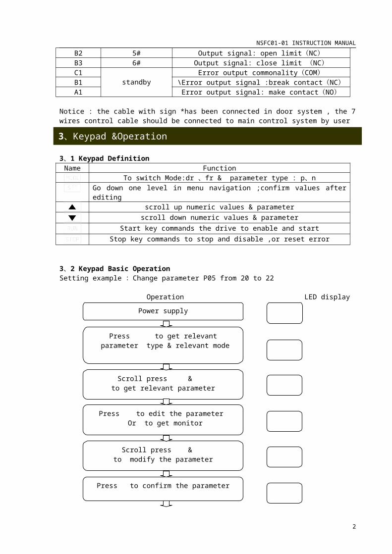
3、2 Keypad Basic OperationSetting example :Change parameter P05 from 20 to 22
Operation LED display
Notice :parameter type d is behind parameter type p . when get parameter type p, continue to press button , can get parameter d.
2
Power supply
Press to get relevant parameter type & relevant mode
Press to edit the parameter Or to get monitor
Scroll press & to get relevant parameter
Scroll press & to modify the parameter
Press to confirm the parameter
Press to returnto operation preparation
NSFC01-01 INSTRUCTION MANUAL
figure 1Notice :
1. Make control line and power line separately when connect to main controller.2. To be sure the match of the open/close door output logic of door controller and the Open/close door input signal logic of main controller, when connect to the signal of Open/close.The initial status of door controller is normal close(NC).
User can select relevant logic status: Terminal A2—open limit, normal open(NO). Terminal A3—close limit, normal open(NO). Terminal (C2-C3)---limit output, signal common terminal.
3
4、Connection Diagrams

NSFC01-01 INSTRUCTION MANUAL
5、1 During(Course of) Open Door1、From DC torque boost level value P05、 acceleration time d28 ,accelerate to start open
frequency P15, then start with target frequency d16 and acceleration time d29 to perform open door low-speed running.
2 when running time d47, start with acceleration time d30 running to high-speed target frequency d17, high-speed frequency be set a common section,d17=d19..
3、when door arrive position of open shift switch, after delay time d48,then start with deceleration time d33 to decelerate to open door low-speed target frequency d20.
4、when door arrive position of open door target position, start with keeping frequency d21,Keeping current d40,to keep torque of door in that position.
Figure 2notice:1. high-speed section of open usually is the same section as: d17=d19, at this point the
acceleration/ deceleration parameter: d32 is void.2. To keep frequency of door opening completed is d21 and the current is d40.
Keep time is d42,and the range is 0.1 to 999(s) ,when d42 is set as 0,it will be keep forever .
3、If opening torque of low-speed is small, the value of P05 can be increased appropriately.but more current course system protect
4
5、Door Run Description

NSFC01-01 INSTRUCTION MANUAL
5、2 Course of close Door1、From torque boost level value P05、acceleration time d34 ,accelerate to low -speed open
frequency d22, to perform original close door running. Then start with target frequency d23 and acceleration time d35, to perform low-speed close door running
2 when running time d49, start with acceleration time d36 running to high-speed target frequency d24, high-speed frequency be set a common section,d24=d26.
3、when door arrive position of open shift switch, after delay time d50,then start with deceleration time d39 to decelerate to open door low-speed target frequency d27.
4、when door arrive position of open door target position, start with keeping frequency d14,Keeping current d41to keep torque of door in that position.
Figure 32. Notice :high-speed section of open usually is the same section as: d24=d26, at this point
the acceleration/ deceleration parameter: d38 is void.2. To keep frequency of door opening completed is d14 and the current is d41.
Keep time is d42,and the range is 0.1 to 999(s) ,when d42 is set as 0,it will be keep forever .
3、If opening torque of low-speed is small, the value of P05 can be increased appropriately. but more current course system protect
Before the door controller is sent out from factory, the Autotune of door width pulses and function parameters are completed. If user requires getting preferable running curve, he can modify the corresponding parameters refer to fig.2 & fig. 3.Procedure is:
1. To set control mode is keypad control: p08=1.2. Refer to fig.2 & fig.3 and corresponding parameters (page:4,5), to get better capability
through adjusting door running curve.
5
6、Basic procedure 1

NSFC01-01 INSTRUCTION MANUAL
3. Press +RUN or +RUN (first press button and then press RUN button, following operation is the same ) to examine the running curve.
4. Set control mode become terminal control: P08=2( default ) NOTICE: if the controller is running, P08 can not be changed. first please press “STOP” key, then press “MODE” key switch to parameter “P” and find P08 to modify
When the motor shift switch or logic of limit switch(NO/NC) is changed, Or autotune the door width pulses is done again. The following procedure must to be sure.
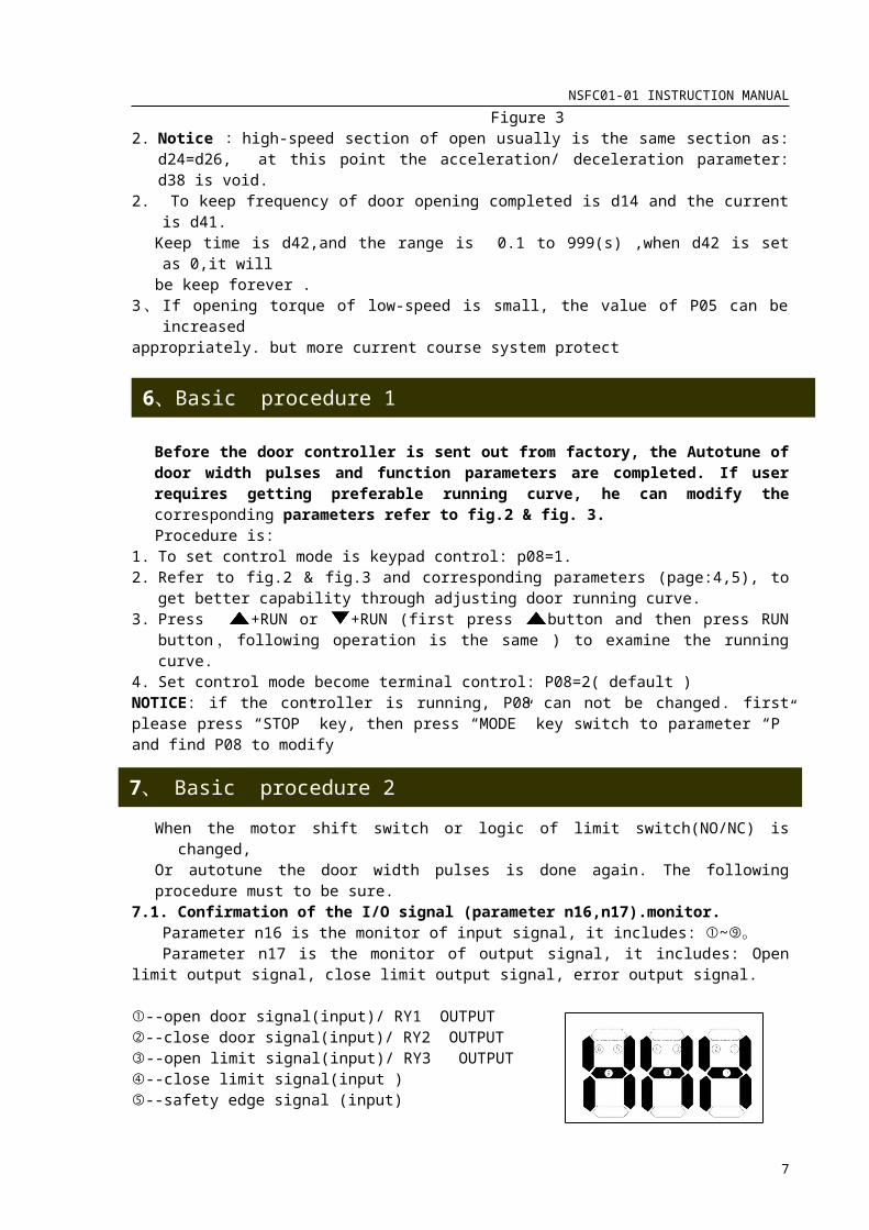
7.1. Confirmation of the I/O signal (parameter n16,n17).monitor.Parameter n16 is the monitor of input signal, it includes: ①~⑨。Parameter n17 is the monitor of output signal, it includes: Open limit output signal, close
limit output signal, error output signal.
①--open door signal(input)/ RY1 OUTPUT②--close door signal(input)/ RY2 OUTPUT③--open limit signal(input)/ RY3 OUTPUT ④--close limit signal(input ) ⑤--safety edge signal (input) ⑥-- open switch speed signal(input) . ⑦-- close switch speed signal(input) figure 4
notice: the terminal⑤,⑧,⑨is not defined,So monitor signal⑤,⑧,⑨ is not work
Press button to switch the parameter n mode ,and press or button To get relevant
monitor parameter, then press , can know the state of signal refer to figure 4 .
7、2 Confirmation of the logic of input signal(NO/NC) The logic of input signal parameter---P431、setting value:0----the signal terminal connect to common terminal of input signal ,the signal is
enable(NO). 1----the signal terminal disconnect to common terminal of input signal, the
signal is enable(NC).2、setting way:Input of the decimal data of 0 to 15 bit. Setting valueweights=total (as the setting value)
For example: the open limit input signal and the close limit input signal are set as NC, and others are set as NO.So the setting value P43=016+08+04+12+11=3
Signal (NULL) Open change signal
Close change signal
Safety edge signal
Open limit signal
Close limit signal
Terminal ------ 7 6 5 4 3power( BIT )
5—15 4 3 2 1 0
value 0 0/1 0/1 0/1 0/1 0/1Total 0 16 8 4 2 1
7.3 affirm of the motor rotation directioncondition:The frequency is set as about 3Hz(in the mode Fr), and P09=0 process:press +RUN button,to sure open of the door;
press +RUN button, to sure close of the door.
6
7、 Basic procedure 2
NSFC01-01 INSTRUCTION MANUAL
notice:1. If motor dose not run, to increase properly the value of parameter P05. 2. If the rotation direction is not right, to change motor phases.
7、4control mode must to be sureThe value of P08
Mode
0 Keypad mode(RUN/STOP)1 Keypad mode( +RUN—open, +RUN—close, STOP)2 Terminal mode(NO:1--open、2--close)3 Communication (RS 485)
7、5running mode must to be sure The value of P09 Control mode 0 manual(the frequency be set in the Fr mode )1 Encoder mode 2 Encoder circle mode 3 Door width pulse autotune4 4 position switch mode 5 4 position switch circle mode 6 Communication mode
NO Name Default Range Multiple Unit editP00 CHECK MODE 0 0-3 1 - RP01 1st ACCELERATION TIME 0.5 0-999 10 s R/WP02 1st DECELERATION TIME 0.5 0-999 10 s R/WP03 FREQUENCY RANGE 0 0-2 1 s RP04 V/F CURVE 0 0-1 1 Code RP05 DC BOOST LEVEL 15 0-40 1 - R/WP06 OVERLOAD FUNCTION 2 0-3 1 % RP07 OVERLOAD CURRENT 3.6 0.1-100 10 - RP08 CONTROL MODE 2 0-3 1 A RP09 RUNNING MODE 4 0-6 1 - RP10 STOP MODE SELECT 0 0-1 1 - RP11 STOP FREQUENCY 0.5 0.50-60 100 - RP12 DC BRAKE TIME 0.5 0-120 10 Hz RP13 DCBRAKE LEVEL 0.0 0-100 0.2 s R P14 MAX. FREQUENCY 50.00 50-250 100 - RP15 BASE FREQUENCY 50.00 45-250 100 Hz RP16 PREVENT OVERCURRENT
STALL 1 0-1 1 Hz R
P17 PREVENT OVERVOLTAGEG STALL
1 0-1 1 Hz R
P18 SKIP FREQUENCY 1 0.00 0,0.5-250 100 Hz RP19 SKIP FREQUENCY 2 0.00 0,0.5-250 100 s RP20 SKIP FREQUENCY 3 0.00 0,0.5-250 100 - RP21 SKIP FREQUENCY BAND
WIDTH0 0-10 1 - R
P22 CURRENT LIMIT FUNCTION
0.0 0-9.9 10 s R
P23 POWER LOSS START MODE
0 0-3 1 - R
7
8、Function Parameter Description

NSFC01-01 INSTRUCTION MANUAL
P24 RIDE-THROUGH RESTART 0 0-2 1 - RP25 WAIT TIME 0.1 0-0.1-
100210 s R
P26 SELECT RETRY 0 0-3 1 - RP27 RETRY TIMES 1 1-10 1 Times RP28 LOWER FREQUENCY CLAMP 0.5 0.5-250 100 Hz RP29 UPPER FREQUENCY
CLAMP 250 0.5-250 100 Hz R
P30 MONITOR SELECT 0 0-1 1 - RP31 LINE 3.0 0.1-100 10 Multiple R/WP32 MAX.OUTPUT VOLTAGE 0 0-500 1 VAC RP33 OCS LEVEL 140 1-200 1 % RP34 CARRIER FREQUENCY 5 0-8 1 Code RP35 COMMUNICATION
STATION1 1-31 1 - R
P36 COMMUNICATION SPEED 5 4-6 1 Code RP37 STOP BIT 1 1-2 1 Bit RP38 PARITY BIT 0 0-2 1 - RP39 COMMUNICATION 0.0 0.0-60.0 10 s RP40 COMMUNICATION
RESPOND TIME1 1-999 1 ms R
P41 PASSWORD 0 0-999 1 - RP42 RESET DATA 0 0-1 1 - RP43 SELECT INPUT SIGNAL LOGIC 27 0-31 1 - RP44 SAFETY EDGE RESPOND TIME 10 0-999 1 ms RP45 POSITION SIGNAL RESPOND
TIME 10 1-999 1 ms R
P46 ENCODE ERROR RESPOND TIME
0.0 0-2.0 10 s R
P47 PROSITION SIGNAL ERROR RESPOND TIME
0.0 0-10.0 10 s R
P48 RY1 OUTPUT FUNCTION SELECT
7 0-15 1 - R
P49 RY2 OUTPUT FUNCTION SELECT
4 0-15 1 - R
P50 RY3 OUTPUT FUNCTION SELECT
5 0-15 1 - R
P51 MOTOR PHASE 6 2-6 0.5 Pole RP52 ENCODE LINE ---- 100-999 1 Pulse RP53 SYSTEM PARAMETER (DON’T
CHANGE)0 0-1 1 - R
P54 SYSTEM PARAMETER (DON’T CHANGE)
1.0 0.1-999 10 Multiple R/W
P55 SYSTEM PARAMETER (DON’T CHANGE)
0.0 0-999 10 s R/W
P56 SYSTEM PARAMETER (DON’T CHANGE)
0.1 0.1-999 10 Multiple R/W
P57 SYSTEM PARAMETER (DON’T CHANGE)
0.0 0-999 10 s R/W
P58 SYSTEM PARAMETER (DON’T CHANGE)) 5.00 0.5-250 100 Hz R/W
P59 OVERLOAD FREQUENCY 1 10.00 0.5-250 100 Hz R/WP60 OVERLOAD FREQUENCY 2 50.00 0.5-250 100 Hz R/W
8

NSFC01-01 INSTRUCTION MANUAL
P61 OVERLOAD CURRENT 1 1.2 0.1-100 100 A R/WP62 OVERLOAD CURRENT 2 1.2 0.1-100 100 A R/WP63 OVERLOAD RESPOND TIME 0 0-999 1 ms R/WP64 OVERLOAD FREQUENCY
RATE(LOW SPEED) 50.00 0-100 100 % R/W
P65 OVERLOAD FREQUENCYRATE(HIGH SPEED) 70.00 0-100 100 % R/W
P66 OVERLOADSWITCH FREQUENCY
5.00 0.5-250 100 Hz R/W
P67 OVERLOAD RESPOND TIME 100 0-999 1 ms R/WP68 BEGIN RUN RESPOND TIME 200 100-999 1 ms R/WP69 FORCE TO OPEN DOOR
RESPOND TIME 0.0 0-500 10 s R/W
P70 ABNORMAL OPEN RESPOND TIME
0.0 0-500 10 s R/W
P71 ABNORMAL OPEN COMPLETE WAITE TIME
0.0 0-10.0 10 s R/W
P72 KEEP OPEN TIME (RECYCLE MODE)
3.0 0-10 10 s R/W
P73 KEEP CLOSE TIME (RECYCLE MODE)
3.0 0-10 10 s R/W
P74 ACCLE/DECELE CURVE SELECT
1 0-2 1 - R/W
P75 OPEN/CLOSE STOP MODESELECT
0 0-1 1 - R/W
D00 CHECK PARAMETER D PASSWORD
0 0-999 1 - R/W
D01 DOOR WIDTH PULSE DEP 0-65535 1 - R/WD02 CLOSE COMPLETE POSITION 0.00 0-100 100 % R/WD03 OPEN CHANGE SPEED
POSITION 11.50 0-100 100 % R/W
D04 OPEN CHANGE SPEED POSITION 2
16.00 0-100 100 % R/W
D05 OPEN CHANGE SPEED POSITION 3
50.00 0-100 100 % R/W
D06 OPEN CHANGE SPEED POSITION 4
70.00 0-100 100 % R/W
D07 OPEN CHANGE SPEED POSITION 5
80.00 0-100 100 % R/W
D08 OPEN COMPLETE POSITION 100.00 0-100 100 % R/WD09 CLOSE COMPLETE POSITION 1 95.00 0-100 100 % R/WD10 CLOSE COMPLETE POSITION 2 75.00 0-100 100 % R/WD11 CLOSE COMPLETE POSITION 3 55.00 0-100 100 % R/WD12 CLOSE COMPLETE POSITION 4 15.00 0-100 100 % R/WD13 CLOSE COMPLETE POSITION 5 13.00 0-100 100 % R/WD14 KEEP CLOSE DOOR
FREQUENCY 2.00 0-250 100 Hz R/W
D15 OPEN DOOR FREQUENCY 1 2.00 0-250 100 Hz R/WD16 OPEN DOOR FREQUENCY 2 2.00 0-250 100 Hz R/WD17 OPEN DOOR FREQUENCY 3 23.00 0-250 100 Hz R/WD18 OPEN DOOR FREQUENCY 4 21.00 0-250 100 Hz R/WD19 OPEN DOOR FREQUENCY 5 23.00 0-250 100 Hz R/WD20 OPEN DOOR FREQUENCY 6 3.00 0-250 100 Hz R/WD21 KEEP OPEN DOOR
FREQUENCY 3.00 0-250 100 Hz R/W
9

NSFC01-01 INSTRUCTION MANUAL
D22 CLOSE DOOR FREQUENCY 1 3.00 0-250 100 Hz R/WD23 CLOSE DOOR FREQUENCY 2 3.00 0-250 100 Hz R/WD24 CLOSE DOOR FREQUENCY 3 19.00 0-250 100 Hz R/WD25 CLOSE DOOR FREQUENCY 4 20.00 0-250 100 Hz R/WD26 CLOSE DOOR FREQUENCY 5 19.00 0-250 100 Hz R/WD27 CLOSE DOOR FREQUENCY 6 2.00 0-250 100 Hz R/WD28 OPEN ACCE/DECE TIME 1 0.5 0.0-999 10 s R/WD29 OPEN ACCE/DECE TIME 2 0.5 0.0-999 10 s R/WD30 OPEN ACCE/DECE TIME 3 1.20 0.0-999 10 s R/WD31 OPEN ACCE/DECE TIME 4 0.5 0.0-999 10 s R/WD32 OPEN ACCE/DECE TIME 5 0.5 0.0-999 10 s R/WD33 OPEN ACCE/DECE TIME 6 1.00 0.0-999 10 s R/WD34 CLOSE ACCE/DECE TIEM 1 0.5 0.0-999 10 s R/WD35 CLOSE ACCE/DECE TIEM 2 0.5 0.0-999 10 s R/WD36 CLOSE ACCE/DECE TIEM 3 1.00 0.0-999 10 s R/WD37 CLOSE ACCE/DECE TIEM 4 0.5 0.0-999 10 s R/WD38 CLOSE ACCE/DECE TIEM 5 0.5 0.0-999 10 s R/WD39 CLOSE ACCE/DECE TIEM 6 1.00 0.0-999 10 s R/WD40 KEEP OPEN DOOR CURRENT 0.5 0-100 10 A R/WD41 KEEP CLOSE DOOR CURRENT 0.4 0-100 10 A R/WD42 KEEP OPEN/CLOSE DOOR
TIME0 0-999 10 s R/W
D43 OPEN COMPLETE STAY FREQUENCY
0.50 0.5-250 100 Hz R/W
D44 CLOSE COMPLETE STAYFREQUENCY
0.50 0.5-250 100 Hz R/W
D45 OPEN COMPLETE STAY TIME 0 0-10 10 s R/WD46 CLOSE COMPLETE STAY
TIME 0 0-10 10 s R/W
D47 BEGIN OPEN DOOR TIME(4SW MODE ) 0.30 0-3 100 s R/W
D48 BEGIN OPEN DOOR CHANGE SPEED TIME (4SW MODE) 0.00 0-3 100 s R/W
D49 BEGIN CLOSE DOOR TIME(4SW MODE ) 0.30 0-3 100 s R/W
D50 BEGIN OPEN DOOR CHANGE SPEED TIME (4SW MODE) 0.00 0-3 100 s R/W
D51 THE FREQUENCY OF POWER ON
3.00 0.5-250 100 Hz R/W
D52 DOOR WIDTH AUTOTONE 2.00 0.5-250 100 Hz R/WD53 PARAMETER D PASSWORD 0 0-999 1 - R/W
9、1 Surveillant parameterNO NAME PRECISION UNIT REMARK
n00 SOFTWARE NO. CODEn01 OUTPUT
FREQUENCY 0.001 Hz
n02 OUTPUT CURRENT
0.1 A
n03 OUTPUT VOLTAGE
0.1 Vac
n04 INPUT DC 0.1 Vdc
10
9、Troubleshooting

NSFC01-01 INSTRUCTION MANUAL
VOLTAGEn05 THE SET
FREQUENCY 0.01 Hz
n06 REBACK FREQUENCY
0.01 Hz MUST TO MOTOT PHASE ,ENCODE LINES
n07 DOOR POSITION AREA
1 0-7:OPEN DOOR AREA;8-13:CLOSE DOOR AREA
n08 DOOR WIDTH(PULSE) 0.01 0.01=1;100=10000
n09 DOORCOMPLETEPOSITION( DATA)
0.01
n10 DOOR RUN TIMES 1 TIME 0.01=1 TIME;100=10000TIMEn11 ENCODE REBACK
STATE0.1 kHz F:(OPEN)R:(CLOSE)
n12 ERROR 1
CODEn13 ERROR 2n14 ERROR 3n15 ERROR 4n16 INPUT SIGNAL
STATEn17 OUTPUT SIGNAL
STATE
9、2 Error CodePANEL SHOW
ERROR CONTENT
REASON REMEDY Relevant parameter
SC1 Over current or abnormal heating
Output .earth short ambient temperature
Is too high Acceleration time isToo short
Check for output short circuits and ground faults Check ambient temperature and fan operationIncrease the acceleration time
Acceleration timeSC2
SC3
OC1Over current
Output less phase Dc boost level is tooHigh Acceleration is too short
Check for open circuit output phases Increase the acceleration time Adjust the boost level
Acceleration/deceleration time P05
OC2OC3
OV1 Excessive internal DC voltage during deceleration(overv
oltage)
Deceleration time is too short
Increase the acceleration time Connect a brake resistor
Acceleration/deceleration time P17
OV2OV3
LV Supply voltage
drops to 85% or
less of rating
(undervoltage)
Voltage supply is lowInstantaneous powerCut
Measure the supply voltageConsider the ride-through restart function
P23-25
11

NSFC01-01 INSTRUCTION MANUAL
OL An output current that is 125% or
more of the electronic thermal setting current or 150% or more of
the inverter’s rated current continued for one minute or more.(overload)
Actuating of Thermal relay Overload
Check the electronic thermal setting current Reduce the load
P05P06,P07
AU An auxiliary fault stop signal was
input from control circuit terminal (auxiliary stop)
Emergency stop signal is send
Inspect the sequence circuit to confirm that the auxiliary signal is correct
OP The operation panel was input
from control circuit terminal (auxiliary
stop)
When power is,the run signal is ONWhen running,the keypad is shell Communication is overtime
Take care with the handing of the operation panelCheck the run signal when the data is being set Check the POWER LOSS START MODE
P23P39
Er1Encode no pulse input
Encode is not pulse input
To sure the encode power ,the encode connect
P51,P52P46
Er2 Encode phase is wrong
Encode A/B phase isNot right
To sure the encode A/B phase
P51,P52P46
Er3 The open/closeComplete input are ON
The open/close complete input are ON
To sure the open/close input signal
P43P45
Er4 The open complete input is not receive
Door width pulse is show the door open complete ,but the open complete signal is not receive
To sure the openComplete signal
P43P45
Er5 The close complete input is not receive
Door width pulse is show the door close complete ,but the close complete signal is not receive
To sure the closeComplete signal
P43P45
Annotions:After the parameter had been setted completely,in rder to prevent change the parameter by accident ,you can set password.Parameter P41: full section password(include all the parameter of Pand d) to set The range of password is 1 to 999 (if you set as 000, it means no password)When you have setted passwoed ,if you want to change the parameter,you should following this:First press “STOP”key to stop the controller,then press “MODE”key 4 timesIf you see word “ps”is glittering ,please press or key to input your password Press “SET” key ,you can change the parameter.(the controller is no password from factory, if you want to set ,please record password to prevent forget)
12