Embed Size (px)
Citation preview

FORM NO. L-21180-F-09141
FORM NO. L-21180-F-0914
WEB CONTROL PRODUCTSUser Manual
Tension Control BrakesBTBA-10, BTBA-12
2FORM NO. L-21180-F-0914
Copyright 2014 Nexen Group, Inc.
Nexen Group, Inc.560 Oak Grove Parkway
Vadnais Heights, Minnesota 55127
ISO 9001 Certified
This document is the original, non-translated, version.
Conformity Declaration: In accordance with Appendix II B of CE Machinery Directive (2006/42/EC):
A Declaration of Incorporation of Partly Completed Machinery evaluation for the applicable EU directives was carried out for this product in accordance with the Machinery Directive. The declaration of incorporation is set out in writing in a separate document and can be requested if required.
This machinery is incomplete and must not be put into service until the machinery into which it is to be incorporated has been declared in conformity with the applicable provisions of the Directive.
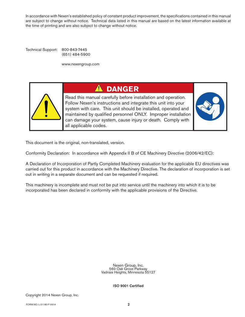
Read this manual carefully before installation and operation. Follow Nexen’s instructions and integrate this unit into your system with care. This unit should be installed, operated and maintained by qualified personnel ONLY. Improper installation can damage your system, cause injury or death. Comply with all applicable codes.
DANGER
In accordance with Nexen’s established policy of constant product improvement, the specifications contained in this manual are subject to change without notice. Technical data listed in this manual are based on the latest information available at the time of printing and are also subject to change without notice.
Technical Support: 800-843-7445 (651) 484-5900
www.nexengroup.com

FORM NO. L-21180-F-09143
Table of Contents
General Specifications -------------------------------------------------------------------------------------------------------------------------- 4
General Safety Precautions ------------------------------------------------------------------------------------------------------------------- 4
Introduction ------------------------------------------------------------------------------------------------------------------------------------------ 5
Installation ------------------------------------------------------------------------------------------------------------------------------------------- 6
Lubrication ------------------------------------------------------------------------------------------------------------------------------------------- 7
Air Connections ----------------------------------------------------------------------------------------------------------------------------------- 8
Operation -------------------------------------------------------------------------------------------------------------------------------------------- 9
Friction Facing Assembly -------------------------------------------------------------------------------------------------------------------- 10
Brake Replacement Assembly ------------------------------------------------------------------------------------------------------------- 11
Fan Replacement Assembly ---------------------------------------------------------------------------------------------------------------- 13
Troubleshooting ---------------------------------------------------------------------------------------------------------------------------------- 14
Replacement Parts ----------------------------------------------------------------------------------------------------------------------------- 15
Anti-Rotation -------------------------------------------------------------------------------------------------------------------------------------- 16
Facing and Repair Kits ----------------------------------------------------------------------------------------------------------------------- 17
Accessories --------------------------------------------------------------------------------------------------------------------------------------- 17
Warranty -------------------------------------------------------------------------------------------------------------------------------------------- 18
4FORM NO. L-21180-F-0914
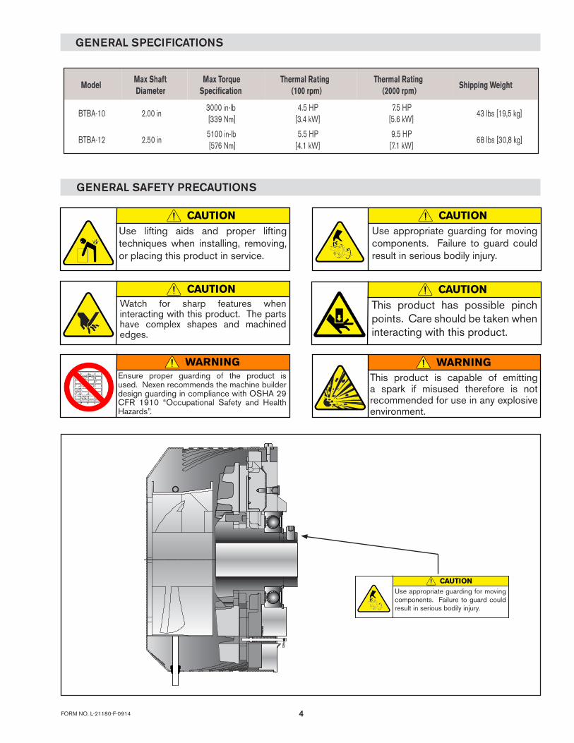
GENERAL SPECIFICATIONS
GENERAL SAFETY PRECAUTIONS
CAUTIONUse lifting aids and proper lifting techniques when installing, removing, or placing this product in service.
CAUTIONWatch for sharp features when interacting with this product. The parts have complex shapes and machined edges.
CAUTIONUse appropriate guarding for moving components. Failure to guard could result in serious bodily injury.
WARNINGEnsure proper guarding of the product is used. Nexen recommends the machine builder design guarding in compliance with OSHA 29 CFR 1910 “Occupational Safety and Health Hazards”.
CAUTIONThis product has possible pinch points. Care should be taken when interacting with this product.
CAUTIONUse appropriate guarding for moving components. Failure to guard could result in serious bodily injury.
ModelMax ShaftDiameter
Max TorqueSpecification
Thermal Rating(100 rpm)
Thermal Rating(2000 rpm)
Shipping Weight
BTBA-10 2.00 in3000 in-lb[339 Nm]
4.5 HP[3.4 kW]
7.5 HP[5.6 kW]
43 lbs [19,5 kg]
BTBA-12 2.50 in5100 in-lb[576 Nm]
5.5 HP[4.1 kW]
9.5 HP[7.1 kW]
68 lbs [30,8 kg]
WARNINGThis product is capable of emitting a spark if misused therefore is not recommended for use in any explosive environment.

FORM NO. L-21180-F-09145
INTRODUCTION
The Nexen BTBA is a tension control brake designed for shaftless unwinds. It is ideal for web control applications such as corrugating and labeling or any application that requires web control.
The BTBA, a pneumatic brake, uses individual pistons to achieve different torque ranges. All pistons are the same size and they each push on individual facings. The facings are quick change facings which are easily replaced in minutes. The brake features an aluminum protective guard that covers the rotating parts of the brake. This guard also houses an electric fan that cools the rotor and maintains a high thermal dissipation at low rotational speeds. The BTBA brake is shaft mounted with a Taper-Lock® bushing. Bore sizes that are under the model’s max bore size require a straight support bushing.
For Installation: Phillips head screw driver Mechanical press 7/32 inch Allen wrench or hex socket (BTBA-10) 1/4 inch Allen wrench or hex socket (BTBA-12) 10 mm Allen wrench or hex socket (BTBA-12) 8 mm Allen wrench or hex socket (BTBA-10)
For Air Line Connections: 7/16 inch open end wrench
For Friction Facing Assembly: Insulated gloves
For BTBA Brake Replacement Assembly: Phillips head screw driver Retaining ring pliers (for both internal and external
retaining rings) Mechanical press 6mm Allen wrench or hex socket (BTBA-10) - 8mm
(BTBA-12) Safety Solvent Loctite® 242 and 680 Small clamp Insulated gloves
For Fan Replacement Assembly: Loctite® 242 3mm Allen wrench Insulated gloves
What you Will need:
A
K(Approx.)
B C (2 at 180°)Anti-rotation holes
3 Conductor Cable18 AWG Wire115 VAC, 61 W
Air Fitting Accepts 4.00 Tube0.156 (5/32)
D
H
M
J
45.0°GF
EN
O
(2 at 180°) P anti-rotation holes
Q
(BTBA-12 Shown)
Figure 1 / Table 1
BTBA-10 & -12 Approximate Dimensions mm[in]
Model A B C D E F G H J M N O P Q
BTBA-10ø240.00[9.449]
10°13.49
[0.531]ø277.0[10.91]
124.95[4.919]
109.75[4.321]
24.49[0.964]
163.03[6.418]
210.8[8.30]
275.0[10.83]
187.9[7.40]
240.00[9.449]
M12-1.75 110°
BTBA-12ø300.00[11.811]
42° M12-1.75ø330.00[12.99]
123.69[4.870]
119.81[4.717]
25.0[0.98]
191.3[7.53]
ø263.9[10.39]
ø327.4[12.89]
220.5[2.68]
300.00[11.811]
13.49[0.531]
4.5°
6FORM NO. L-21180-F-0914
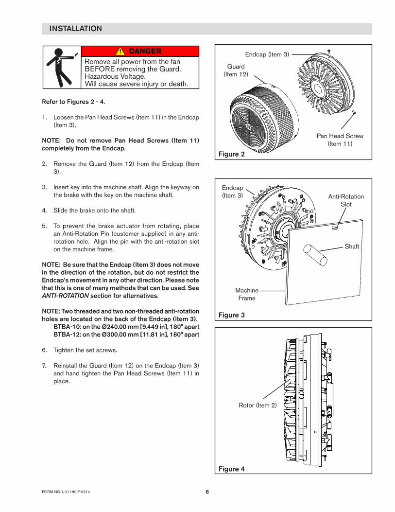
Refer to Figures 2 - 4.
1. Loosen the Pan Head Screws (Item 11) in the Endcap (Item 3).
NOTE: Do not remove Pan Head Screws (Item 11) completely from the Endcap.
2. Remove the Guard (Item 12) from the Endcap (Item 3).
3. Insert key into the machine shaft. Align the keyway on the brake with the key on the machine shaft.
4. Slide the brake onto the shaft.
5. To prevent the brake actuator from rotating, place an Anti-Rotation Pin (customer supplied) in any anti-rotation hole. Align the pin with the anti-rotation slot on the machine frame.
NOTE: Be sure that the Endcap (Item 3) does not move in the direction of the rotation, but do not restrict the Endcap’s movement in any other direction. Please note that this is one of many methods that can be used. See ANTI-ROTATION section for alternatives.
NOTE: Two threaded and two non-threaded anti-rotation holes are located on the back of the Endcap (Item 3). BTBA-10: on the Ø240.00 mm [9.449 in], 180° apart BTBA-12: on the Ø300.00 mm [11.81 in], 180° apart
6. Tighten the set screws.
7. Reinstall the Guard (Item 12) on the Endcap (Item 3) and hand tighten the Pan Head Screws (Item 11) in place.
INSTALLATION
Figure 2
Pan Head Screw(Item 11)
Guard (Item 12)
Endcap (Item 3)
Figure 3
Anti-Rotation Slot
Shaft
Machine Frame
Endcap (Item 3)
Figure 4
Rotor (Item 2)
DANGERRemove all power from the fan BEFORE removing the Guard.Hazardous Voltage.Will cause severe injury or death.

FORM NO. L-21180-F-09147
NOTENexen pneumatically actuated devices require clean, pressure regulated air for maximum performance and life. All seals in Nexen Pneumatically operated devices are lubricated for life and do not require additional lubrication.
However, some customers prefer to use an air line lubricator, which injects oil into the pressurized air, forcing an oil mist into the air chamber. This is acceptable, but care must be taken to ensure once an air mist lubrication system is used, it is continually used over the life of the product as the oil mist may wash free the factory installed lubrication.
Locate the lubricator above and within ten feet of the product, and use low viscosity oil such as SAE-10.
Synthetic lubricants are not recommended.
Nexen product's bearings are shielded and pre-lubricated, and require no further lubrication.
LUBRICATOR DRIP RATE SETTINGS
1. Close and disconnect the air line from the unit.
2. Turn the Lubricator Adjustment Knob counterclockwise three complete turns.
3. Open the air line.
LUBRICATION
CAUTIONThese settings are for Nexen supplied lubricators. If you are not using a Nexen lubricator, calibration must follow the manufacturer's suggested procedure.
4. Close the air line to the unit when a drop of oil forms in the Lubricator Sight Gage.
5. Connect the air line to the unit.
6. Turn the Lubricator Adjustment Knob clockwise until closed.
7. Turn the Lubricator Adjustment Knob counterclockwise one-third turn.
8. Open the air line to the unit.

8FORM NO. L-21180-F-0914
NOTE: Refer to Figures 5 and 6.
NOTE: For optimum operation, use clean air filtered to 5 microns or better.
The BTBA-10 has six air ports; the BTBA-12 has eight air ports. All air ports accept 1/8 inch NPT fittings. Use the tee fittings (Item 38) and elbow fittings (Item 37) that are enclosed with the brake. Air line fittings can be made in two configurations.
4-Source control (BtBa-12) For use with four air sources:The air can be interrupted or supplied to any combination of the four pairs of ports. Two opposing ports comprise a pair. The torque output is related to a change in air pressure and the number of pistons used. Always use pistons in opposing pairs.
3-Source control (BtBa-10)For use with three air sources:The air can be interrupted or supplied to any combination of the three pairs of ports. Two opposing ports comprise a pair. The torque output is related to a change in air pressure and the number of pistons used.
1-Source control (BtBa-10 & -12)For use with one air source:Connect all ports together. The 1-Source Control relates the change in torque performance to change in air pressure only.
AIR CONNECTIONS
Figure 5
3-Source
Figure 6
1-Source
CAUTIONONLY use pistons in pairs. The bearings may fail prematurely if you only use one port. If a pair of ports is unbalanced then the bearings may fail prematurely.
AirSupply
Brake Inlet
GaugeRegulatorFilterDryer
Brake Control Circuit
Quick Exhaust Valve
3/2 (3 Way)N.O. Valve
AIR PRESSURE: 8 BAR (120 PSI) ABSOLUTE MAX 0 BAR (0 PSI) ABSOLUTE MIN
NOTEFor quick response, Nexen recommends a quick exhaust valve and short air lines between the Control Valves and the product. Align the air inlet ports to a down position to allow condensation to drain out of the air chambers of the product.
CAUTIONLow air pressure will cause slippage and overheating. Excessive air pressure will cause abrupt starts and stops, reducing product life.
All Nexen pneumatically actuated devices require clean and dry air, which meet or exceeds ISO 8573.1:2001 Class 4.4.3 quality.
The following is a common air supply scheme used with this product. This is an example and not an all-inclusive list. All air circuits to be used with this product must be designed following ISO 4414 guidelines.

FORM NO. L-21180-F-09149
WARNINGNever exceed maximum operating speeds listed for your product. (See Table 1).
OPERATION
TABLE 1
Size Max RPMBTBA-10 2000
BTBA-12 2500
CAUTION
The temperature limits for this product line are 4.5-104 Degree Celsius (40-220 Degree F).
WARNINGEnsure proper guarding of the product is used. Nexen recommends the machine builder design guarding in compliance with OSHA 29 CFR 1910 “Occupational Safety and Health Hazards”.
CAUTIONNever exceed life of facing material. Facing life depends on the volume of material and the total energy over the life of the unit. Expected life (in hrs) can be found by: Time=Volume/(Power*Wear Rate).

10FORM NO. L-21180-F-0914
Refer to Figures 7 - 9.
1. Loosen the Pan Head Screws (Item 11) in the Endcap (Item 3).
NOTE: Do not remove Pan Head Screws (Item 11) completely from the Endcap.
2. Remove the Guard (Item 12) from the Endcap (Item 3).
3. Release a Friction Facing Assembly (Item 4) by pulling the Ring or Finger Nut (Item 42) that is attached to Retaining Pin (Item 7).
4. Slide the old Friction Facing Assembly (Item 4) out of the BTBA.
5. Slide a new Friction Facing Assembly (Item 4) into the BTBA.
6. Release the Ring or Finger Nut (Item 42) that is attached to the Retaining Pin (Item 7). The Retaining Pin (Item 7) locks the new Friction Facing Assembly (Item 4) securely in place.
7. Repeat these steps until you have replaced all six (BTBA-10) or eight (BTBA-12) of the Friction Facing Assemblies (Item 4).
8. Reinstall the Guard (Item 12) to the Endcap (Item 3) and hand tighten the Pan Head Screws (Item 11).
FRICTION FACING ASSEMBLY
Figure 9
Figure 7
Pan Head Screw (Item 11)
Endcap (Item 3)
Guard (Item 12)
Figure 8
( or Finger Nut)
Friction FacingAssembly(Item 4)
Ring(Item 42)
Retaining Pin(Item 7)
DANGERRemove all power from the fan BEFORE removing the Guard.Hazardous Voltage.Will cause severe injury or death.
CAUTION
Surface temperature may exceed safe handling limits during operation. Do not touch.

FORM NO. L-21180-F-091411
Refer to Figures 10 - 13.
1. Loosen the three Pan Head Screws (Item 11) in the Endcap (Item 3).
NOTE: Do not remove Pan Head Screws (Item 11) completely from the Endcap.
2. Remove the Guard (Item 12) from the Endcap (Item 3).
3. Remove the Set Screws.
4. Remove the BTBA from the shaft.
BRAKE REPLACEMENT ASSEMBLY
Figure 11
Cylinder(Item 1)
Hub (Item 5)
Cylinder(Item 1)
Endcap(Item 3)
Socket HeadCap Screws
(Item 6)
FIGURE 12
Figure 10
Pan Head Screw (Item 11)
Endcap (Item 3)
Guard (Item 12)
5. Remove the old Retaining Ring (Item 21) from the Hub (Item 5).
6. Fully support the Cylinder (Item 1) and press out the Hub (Item 5) and Rotor (Item 2).
7. Remove the Friction Facings Assemblies (Item 4) from the Cylinder (Item 1).
8. Remove the Socket Head Cap Screws (Item 6) from the Cylinder (Item 1).
9. Remove the Cylinder (Item 1) from the Endcap (Item 3).
10. Remove the old Diaphragms (Item 14) from the End-cap (Item 3).
11. Remove the old O-rings (Item 33) from the ends of the Pistons (Item 10).
12. Remove the Rings or Finger Nuts (Item 42) from the Retaining Pins (Item 7).
13. Remove the old Compression Springs (Item 19) from the Retaining Pins (Item 7).
14. Remove the old Retaining Ring (Item 40) from the Endcap (Item 3).
DANGERRemove all power from the fan BEFORE removing the Guard.Hazardous Voltage.Will cause severe injury or death.
CAUTION
Surface temperature may exceed safe handling limits during operation. Do not touch.
CAUTIONWorking with spring loaded or tension loaded fasteners and devices can cause injury. Wear safety glasses and take the appropriate safety precautions.
12FORM NO. L-21180-F-0914
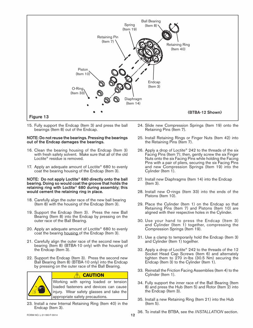
15. Fully support the Endcap (Item 3) and press the ball bearings (Item 8) out of the Endcap.
NOTE: Do not reuse the bearings. Pressing the bearings out of the Endcap damages the bearings.
16. Clean the bearing housing of the Endcap (Item 3) with fresh safety solvent. Make sure that all of the old Loctite® residue is removed.
17. Apply an adequate amount of Loctite® 680 to evenly coat the bearing housing of the Endcap (Item 3).
NOTE: Do not apply Loctite® 680 directly onto the ball bearing. Doing so would coat the groove that holds the retaining ring with Loctite® 680 during assembly; this would cement the retaining ring in place.
18. Carefully align the outer race of the new ball bearing (Item 8) with the housing of the Endcap (Item 3).
19. Support the Endcap (Item 3). Press the new Ball Bearing (Item 8) into the Endcap by pressing on the outer race of the Ball Bearing.
20. Apply an adequate amount of Loctite® 680 to evenly coat the bearing housing of the Endcap (Item 3).
21. Carefully align the outer race of the second new ball bearing (Item 8) (BTBA-10 only) with the housing of the Endcap (Item 3).
22. Support the Endcap (Item 3). Press the second new Ball Bearing (Item 8) (BTBA-10 only) into the Endcap by pressing on the outer race of the Ball Bearing.
23. Install a new Internal Retaining Ring (Item 40) in the Endcap (Item 3).
Retaining Pin(Item 7)
Diaphragm(Item 14)
Piston(Item 10)
O-Ring(Item 33)
Retaining Ring(Item 40)
Ball Bearing(Item 8)
Endcap(Item 3)
Spring(Item 19)
Figure 13(BTBA-12 Shown)
24. Slide new Compression Springs (Item 19) onto the Retaining Pins (Item 7).
25. Install Retaining Rings or Finger Nuts (Item 42) into the Retaining Pins (Item 7).
26. Apply a drop of Loctite® 242 to the threads of the six Facing Pins (Item 7); then, gently screw the six Finger Nuts onto the six Facing Pins while holding the Facing Pins with a pair of pliers, securing the six Facing Pins and new Compression Springs (Item 19) into the Cylinder (Item 1).
27. Install new Diaphragms (Item 14) into the Endcap (Item 3).
28. Install new O-rings (Item 33) into the ends of the Pistons (Item 10).
29. Place the Cylinder (Item 1) on the Endcap so that Retaining Pins (Item 7) and Pistons (Item 10) are aligned with their respective holes in the Cylinder.
30. Use your hand to press the Endcap (Item 3) and Cylinder (Item 1) together, compressing the Compression Springs (Item 19).
31. Use a clamp to temporarily hold the Endcap (Item 3) and Cylinder (Item 1) together.
32. Apply a drop of Loctite® 242 to the threads of the 12 Socket Head Cap Screws (Item 6) and alternately tighten them to 270 in-lbs (30.5 Nm) securing the Endcap (Item 3) to the Cylinder (Item 1).
33. Reinstall the Friction Facing Assemblies (Item 4) to the Cylinder (Item 1).
34. Fully support the inner race of the Ball Bearing (Item 8) and press the Hub (Item 5) and Rotor (Item 2) into the Endcap (Item 3).
35. Install a new Retaining Ring (Item 21) into the Hub (Item 5).
36. To install the BTBA, see the INSTALLATION section.
CAUTIONWorking with spring loaded or tension loaded fasteners and devices can cause injury. Wear safety glasses and take the appropriate safety precautions.

FORM NO. L-21180-F-091413
FAN REPLACEMENT ASSEMBLY
Refer to Figures 14 - 17.
1. Loosen the Pan Head Screws (Item 11) in the Endcap (Item 3).
NOTE: Do not remove Pan Head Screws (Item 11) completely from the Endcap.
2. Remove the Guard (Item 12) from the Endcap (Item 3).
3. Remove the four Socket Head Cap Screws (Item 22) from the Guard (Item 12).
4. Remove the two female Slip On Terminals (Item 34) from the Fan (Item 35).
5. Remove the old Fan (Item 35).
6. Align the new Fan (Item 35) with the mounting standoffs on the guard (Item 12).
7. Apply a drop of Loctite® 242 to the threads of the four Socket Head Cap Screws (Item 22). Secure the Fan (Item 35), Ring Terminal (Item 23) and External Tooth Washer (Item 41) to the Guard (Item 12). The green and yellow wire that is connected to the Ring Terminal (Item 23) is the ground wire.
NOTE: There is only one External Tooth Washer (Item 41). It assembles on the Socket Head Cap Screw (Item 22) that goes through the Ring Terminal (Item 23).
8. Push the two Female Slip-On Terminals (Item 34) on the spade terminals of the Fan (Item 35).
9. Reinstall the Guard (Item 12) to the Endcap (Item 3) and hand tighten the Pan Head Screws (Item 11) in place.
Figure 16
Figure 14
Pan Head Screw (Item 11)
Endcap (Item 3)
Guard (Item 12)
Figure 17
Female Slip-on Terminal (Item 34)
Tooth Washer (External) (Item 41)
Socket Head Cap Screw (Item 22)
Ring Terminal (Item 23)
Green/Yellow Wire (Ground)
Fan (Item 35)
Figure 15
Socket Head Cap Screws
Slip Terminals
DANGERRemove all power from the fan BEFORE removing the Guard.Hazardous Voltage.Will cause severe injury or death.
CAUTION
Surface temperature may exceed safe handling limits during operation. Do not touch.
14FORM NO. L-21180-F-0914
TROUBLESHOOTING
SYMPTOM PROBABLE CAUSE SOLUTION
Failure to engage. Air not getting to the BTBA.Check for a control valve malfunction or low airpressure.
Failure to disengage. Unexhausted air. Check for a control valve malfunction.
Friction facing squeal or chatter.Air pressure too high. Reduce the air pressure.
Wrong friction facings for the application. Consult Nexen for the correct friction facing.
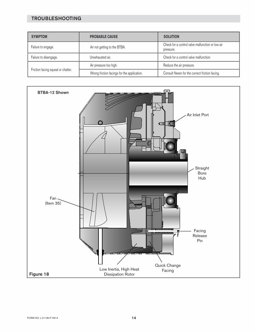
Figure 18
Fan(Item 35)
Straight Bore Hub
Facing Release
Pin
Air Inlet Port
Quick Change FacingLow Inertia, High Heat
Dissipation Rotor
BTBA-12 Shown

FORM NO. L-21180-F-091415
REPLACEMENT PARTS
FIGURE 19 33
10
14
42
7
19
3
6
8
40
14
9
2
5
22
35
12
21
25
23
2441
34
The item or balloon number for all Nexen products is used for part identification on all product parts lists, product price lists, unit assembly drawings, bills of materials, and instruction manuals.
When ordering replacement parts, specify model designation, item number, part description, and quantity. Purchase replacement parts through your local Nexen Distributor.
* Retaining Pin (Item 7) is no longer available with hole for Ring Handle. When ordering replacement Retaining Pin (Item 7), order (Item 42) Finger Nut if unit is Ring Handle style.
Item Description BTB-10 Qty
BTB-12 Qty
12 3
CylinderRotor
Endcap
111
111
456
Friction FacingHub
Cap Screw
61
12
81
16
789
Retaining PinBall BearingCap Screw
628
819
101112
PistonPan Hd Screw (not shown)
Guard
631
831
141921
DiaphragmCompression SpringRetaining Ring (Ext.)
661
881
22 Socket Head Cap Screw 4 4
Item Description BTB-10 Qty
BTB-12 Qty
232425
Terminal Ring (Insulated)Socket Head Cap Screw
Cable
1- -1
111
273334
Strain Relief BushingO-Rings
Slip On Terminal (Insulated)
162
182
353738
FanElbow Fitting (not shown)
Tee Fitting (not shown)
135
147
394041
Tubing (not shown)Retaining Ring (Int.)Lock Washer (Ext.)
111
111
424344
* Ring Handle or Finger NutKey (not shown)
Set Screws (not shown)
613
813

16FORM NO. L-21180-F-0914
ANTI-ROTATION
Assembled View
Exploded View
Machine Frame
Threaded standoff with hole to accept a pin or the head of a M12 Screw
M12 Screw
Figure 21
The BTBA allows for several anti-rotation methods. The primary goal is to prevent the brake actuator from rotating. Nexen suggests one of the following possibilities:
• Bracket (See Figure 20 below) • Threaded Spacer (See Figure 21 below) • Threaded Rod and Jam Nuts
Anti-Rotation BracketMachine Frame
Side View Isometric View
Figure 20
Please note that these are only suggestions. For further assistance, please contact Nexen.

FORM NO. L-21180-F-091417
FACING AND REPAIR KITS
Model Kit Type Contents Product Number
BTBA-10
Standard Facing Kit Standard facings 927434
Low Coeficient (LoCo) Facing Kit LoCo facings 927435
Repair Kit Diaphragms and bearing 927436
BTBA-12
Standard Facing Kit Standard facings 927539
Low Coeficient (LoCo) Facing Kit LoCo facings 927540
Repair Kit Diaphragms and bearing 927541
Moving parts can crush or cut.
Do not operate with the guard removed.
WARNING
ACCESSORIES
Label, Warning, Guard, BTBA 17214Sticker, Warning, Read, Manual 17189Warning, Danger, Wiring, BTBA 17215
Please inspect the warning labels on your unit regularly and replace any that are missing or not visible. The labels on this unit are displayed below. To order replacement labels, indicate part number and quantity. Replacement labels are available through your Nexen distributor.
17214
17215
Remove all power from the fan BEFORE removing the Guard.Hazardous Voltage.Will cause severe injury or death.
DANGER
To avoid injury,read and understandthe user manual beforeyou use this unit.
WARNING
17189

18FORM NO. L-21180-F-0914
Nexen Group, Inc.560 Oak Grove ParkwayVadnais Heights, MN 55127
800.843.7445Fax: 651.286.1099www.nexengroup.com
ISO 9001 Certified
WARRANTY
WarrantiesNexen warrants that the Products will (a) be free from any defects in material or workmanship for a period of 12 months from the date of shipment, and (b) will meet and perform in accordance with the specifications in any engineering drawing specifically for the Product that is in Nexen’s current product catalogue, or that is accessible at the Nexen website, or that is attached to this Quotation and that specifically refers to this Quotation by its number, subject in all cases to any limitations and exclusions set out in the drawing. NEXEN MAKES NO OTHER WARRANTY, EXPRESS OR IMPLIED, AND ALL IMPLIED WARRANTIES, INCLUDING WITHOUT LIMITATION, IMPLIED WARRANTIES OF MERCHANTABILITY AND FITNESS FOR A PARTICULAR PURPOSE ARE HEREBY DISCLAIMED. This warranty applies only if: (a) the Product has been installed, used and maintained in accordance with any applicable Nexen installation or maintenance manual for the Product; (b) the alleged defect is not attributable to normal wear and tear; (c) the Product has not been altered, misused or used for purposes other than those for which it was intended; and (d) Buyer has given written notice of the alleged defect to Nexen, and delivered the allegedly defective Product to Nexen, within one year of the date of shipment.
Exclusive RemedyThe exclusive remedy for the Buyer for any breach of any warranties provided in connection with this agreement will be, at the election of Nexen: (a) repair or replacement with new, serviceably used, or reconditioned parts or products; or (b) issuance of credit in the amount of the purchase price paid to Nexen by the Buyer for the Products.
Agent's AuthorityBuyer agrees that no agent, employee or representative of Nexen has authority to bind Nexen to any affirmation, representation, or warranty concerning the Products other than those warranties expressly set forth herein.
Limitation on Nexen’s LiabilityTO THE EXTENT PERMITTED BY LAW NEXEN SHALL HAVE NO LIABILITY TO BUYER OR ANY OTHER PERSON FOR INCIDENTAL DAMAGES, SPECIAL DAMAGES, CONSEQUENTIAL DAMAGES OR OTHER DAMAGES OF ANY KIND OR NATURE WHATSOEVER, WHETHER ARISING OUT OF BREACH OF WARRANTY OR OTHER BREACH OF CONTRACT, NEGLIGENCE OR OTHER TORT, OR OTHERWISE, EVEN IF NEXEN SHALL HAVE BEEN ADVISED OF THE POSSIBILITY OR LIKELIHOOD OF SUCH POTENTIAL LOSS OR DAMAGE. For all of the purposes hereof, the term "consequential damages" shall include lost profits, penalties, delay damages, liquidated damages or other damages and liabilities which Buyer shall be obligated to pay or which Buyer may incur based upon, related to or arising out of its contracts with its customers or other third parties. In no event shall Nexen be liable for any amount of damages in excess of amounts paid by Buyer for Products or services as to which a breach of contract has been determined to exist. The parties expressly agree that the price for the Products and the services was determined in consideration of the limitation on damages set forth herein and such limitation has been specifically bargained for and constitutes an agreed allocation of risk which shall survive the determination of any court of competent jurisdiction that any remedy herein fails of its essential purpose.
InspectionBuyer shall inspect all shipments of Products upon arrival and shall notify Nexen in writing, of any shortages or other failures to conform to these terms and conditions which are reasonably discoverable upon arrival without opening any carton or box in which the Products are contained. Such notice shall be sent within 14 days following arrival. All notifications shall be accompanied by packing slips, inspection reports and other documents necessary to support Buyer's claims. In addition to the foregoing obligations, in the event that Buyer receives Products that Buyer did not order, Buyer shall return the erroneously shipped Products to Nexen within thirty (30) days of the date of the invoice for such Products; Nexen will pay reasonable freight charges for the timely return of the erroneously shipped Products, and issue a credit to Buyer for the returned Products at the price Buyer paid for them, including any shipping expenses that Nexen charged Buyer. All shortages, overages and nonconformities not reported to Nexen as required by this section will be deemed waived.
Limitation on ActionsNo action, regardless of form, arising out of any transaction to which these terms and conditions are applicable may be brought by the Buyer more than one year after the cause of action has accrued.