Embed Size (px)
Citation preview

Web Configuration

Web Configuration
-1-
Table of Contents
Chapter 1 Configuration Preparation .................................................................................................................................... 4
1.1 HTTP Configuration ............................................................................................................................................... 4
1.1.1 Choosing the Prompt Language ............................................................................................................... 4
1.1.2 Setting the HTTP Port ............................................................................................................................... 4
1.1.3 Enabling the HTTP Service ....................................................................................................................... 4
1.1.4 Setting the HTTP Access Mode ................................................................................................................ 4
1.1.5 Setting the Maximum Number of VLAN Entries on Web Page ................................................................. 5
1.1.6 Setting the Maximum Number of Multicast Entries Displayed on a Web Page ......................................... 5
1.2 HTTPS Configuration ............................................................................................................................................ 5
1.2.1 Setting the HTTP Access Mode ................................................................................................................ 5
1.2.2 It is used to set the HTTPS port. ............................................................................................................... 5
Chapter 2 Accessing a Switch .............................................................................................................................................. 6
2.1 Accessing the Switch Through HTTP .................................................................................................................... 6
2.1.1 Initially Accessing the Switch .................................................................................................................... 6
2.1.2 Upgrading to the Web-Supported Version................................................................................................. 7
2.2 Accessing a Switch Through Secure Links ............................................................................................................ 7
2.3 Introduction of Web Interface ................................................................................................................................ 7
2.3.1 Top Control Bar ......................................................................................................................................... 8
2.3.2 Navigation Bar ........................................................................................................................................... 9
2.3.3 Configuration Presentation Area ............................................................................................................. 10
2.3.4 Configuration Area .................................................................................................................................. 10
Chapter 3 Basic Configuration ............................................................................................................................................ 11
3.1 Hostname Configuration ...................................................................................................................................... 11
3.2 Time Management ............................................................................................................................................... 11
Chapter 4 Configuration of the Physical Interface .............................................................................................................. 13
4.1 Configuring Port Description ............................................................................................................................... 13
4.2 Configuring the Attributes of the Port .................................................................................................................. 14
4.3 Rate control ......................................................................................................................................................... 15
4.4 Port Mirror ........................................................................................................................................................... 15
4.5 Loopback Detection ............................................................................................................................................. 16
4.6 Port security ........................................................................................................................................................ 16
4.6.1 IP Binding Configuration.......................................................................................................................... 16
4.6.2 MAC Binding Configuration ..................................................................................................................... 17
4.6.3 Setting the Static MAC Filtration Mode ................................................................................................... 17
4.6.4 Static MAC Filtration Entries ................................................................................................................... 18
4.6.5 Setting the Dynamic MAC Filtration Mode .............................................................................................. 18
4.7 Storm control ....................................................................................................................................................... 19
4.7.1 Broadcast Storm Control ......................................................................................................................... 19
4.7.2 Multicast Storm Control ........................................................................................................................... 19
4.7.3 Unknown Unicast Storm Control ............................................................................................................. 20
Chapter 5 Layer-2 Configuration ........................................................................................................................................ 21
5.1 VLAN Settings ..................................................................................................................................................... 21

Web Configuration
-2-
5.1.1 VLAN List ................................................................................................................................................ 21
5.1.2 VLAN Settings ......................................................................................................................................... 22
5.2 Configuring the VLAN interface ........................................................................................................................... 23
5.3 GVRP Configuration ............................................................................................................................................ 24
5.3.1 Configuring the Global Attributes of GVRP ............................................................................................. 24
5.3.2 Configuring the Attributes of the GVRP Port ........................................................................................... 24
5.4 LLDP Configuration ............................................................................................................................................. 24
5.4.1 Configuring the Global Attributes of LLDP .............................................................................................. 24
5.4.2 Configuring the Attributes of the LLDP Port ............................................................................................ 25
5.5 STP Configuration ............................................................................................................................................... 25
5.5.1 STP Status Information ........................................................................................................................... 25
5.5.2 Configuring the Attributes of the STP Port .............................................................................................. 26
5.6 IGMP-Snooping Configuration ............................................................................................................................ 27
5.6.1 IGMP-Snooping Configuration ................................................................................................................ 27
5.6.2 IGMP-Snooping VLAN List ...................................................................................................................... 27
5.6.3 Static Multicast Address .......................................................................................................................... 28
5.6.4 Multicast List ........................................................................................................................................... 28
5.7 Setting Static ARP ............................................................................................................................................... 29
5.8 Configuring the Static MAC Address ................................................................................................................... 29
5.9 Link Aggregation Configuration ........................................................................................................................... 30
5.9.1 Port Aggregation Configuration ............................................................................................................... 30
5.9.2 Configuring the Link Aggregation Load Balance ..................................................................................... 31
5.10 Ring Protection Configuration ........................................................................................................................... 31
5.10.1 EAPS Ring List ...................................................................................................................................... 31
5.10.2 EAPS Ring Configuration ...................................................................................................................... 32
5.11 Link Backup Configuration ................................................................................................................................. 33
5.11.1 Configuring the Link Backup Protocol Globally ..................................................................................... 33
5.12 DHCP-Snooping Configuration ......................................................................................................................... 33
5.12.1 Configuring the Global Features of DHCP Snooping ............................................................................ 33
5.13 PDP Configuration ............................................................................................................................................. 34
5.13.1 Configuring the Global Attributes of PDP .............................................................................................. 34
5.13.2 Configuring the Attributes of the PDP Port ............................................................................................ 35
Chapter 6 Advanced Configuration .................................................................................................................................... 36
6.1 QoS Configuration ............................................................................................................................................... 36
6.1.1 Configuring QoS Port .............................................................................................................................. 36
6.1.2 Global QoS Configuration ....................................................................................................................... 37
6.2 MAC Access Control List ..................................................................................................................................... 37
6.2.1 Setting the Name of the MAC Access Control List .................................................................................. 37
6.2.2 Setting the Rules of the MAC Access Control List .................................................................................. 38
6.2.3 Applying the MAC Access Control List .................................................................................................... 38
6.3 IP Access Control List.......................................................................................................................................... 39
6.3.1 Setting the Name of the IP Access Control List....................................................................................... 39
6.3.2 Setting the Rules of the IP Access Control List ....................................................................................... 40
6.3.3 Applying the IP Access Control List ......................................................................................................... 41
Chapter 7 Network Management Configuration ................................................................................................................. 42
7.1 SNMP Configuration ............................................................................................................................................ 42

Web Configuration
-3-
7.1.1 SNMP Community Management ............................................................................................................. 42
7.1.2 SNMP Host Management........................................................................................................................ 43
7.2 RMON ................................................................................................................................................................. 43
7.2.1 RMON Statistic Information Configuration .............................................................................................. 43
7.2.2 RMON History Information Configuration ................................................................................................ 44
7.2.3 RMON Alarm Information Configuration .................................................................................................. 45
7.2.4 RMON Event Configuration ..................................................................................................................... 45
Chapter 8 Diagnosis Tools ................................................................................................................................................. 47
8.1 Ping ..................................................................................................................................................................... 47
8.1.1 Ping ......................................................................................................................................................... 47
Chapter 9 System Management ......................................................................................................................................... 49
9.1 User Management ............................................................................................................................................... 49
9.1.1 User List .................................................................................................................................................. 49
9.1.2 Establishing a New User ......................................................................................................................... 50
9.2 Log Management ................................................................................................................................................ 50
9.3 Managing the Configuration Files ........................................................................................................................ 51
9.3.1 Exporting the Configuration Information .................................................................................................. 51
9.3.2 Importing the Configuration Information .................................................................................................. 51
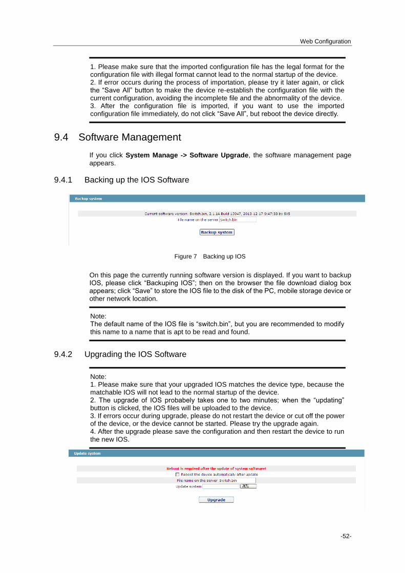
9.4 Software Management ........................................................................................................................................ 52
9.4.1 Backing up the IOS Software .................................................................................................................. 52
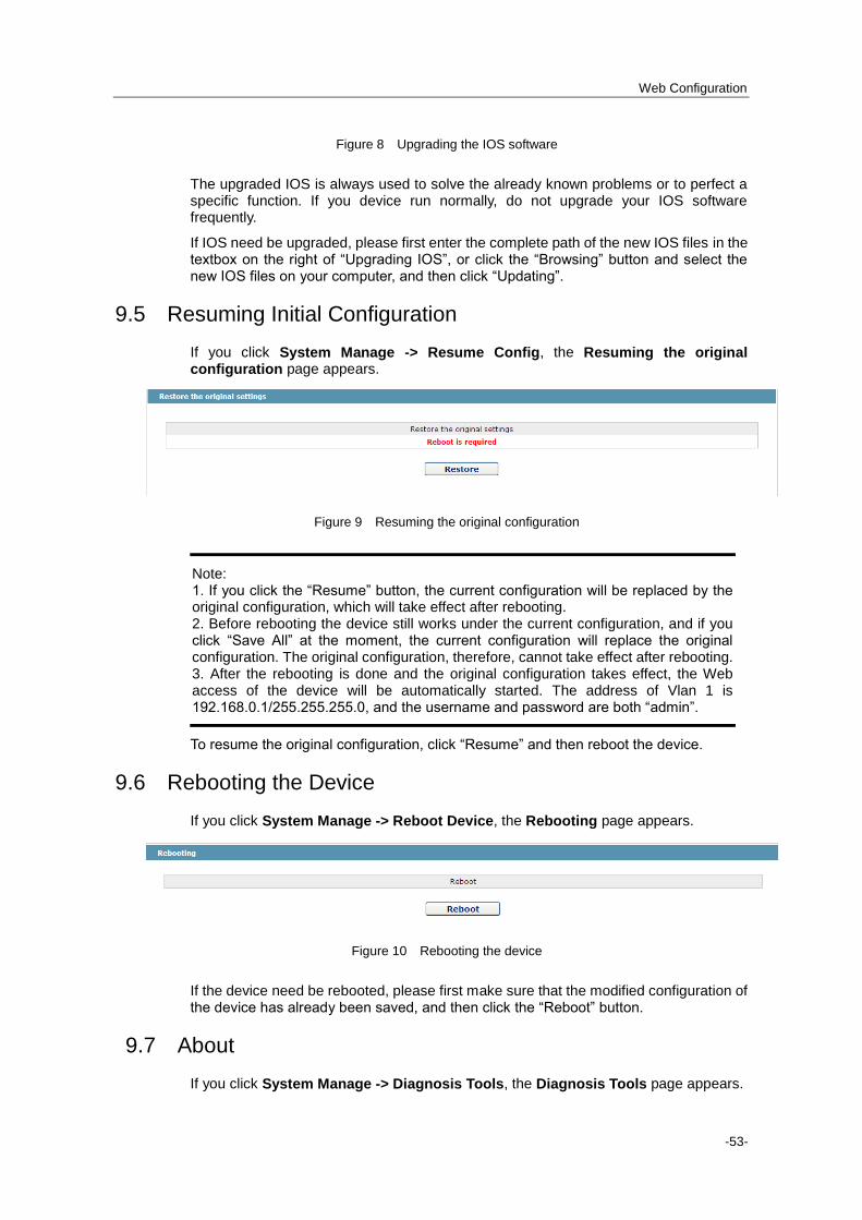
9.4.2 Upgrading the IOS Software ................................................................................................................... 52
9.5 Resuming Initial Configuration ............................................................................................................................ 53
9.6 Rebooting the Device .......................................................................................................................................... 53
9.7 About ................................................................................................................................................................... 53

Web Configuration
-4-
Chapter 1 Configuration Preparation
1.1 HTTP Configuration
Switch configuration can be conducted not only through command lines and SNMP but also through Web browser. The switches support the HTTP configuration, the abnormal packet timeout configuration, and so on.
1.1.1 Choosing the Prompt Language
Up to now, switches support two languages, that is, English and Chinese, and the two languages can be switched over through the following command.
Command Purpose
ip http language {chinese | english}
Sets the prompt language of Web configuration to Chinese or English.
1.1.2 Setting the HTTP Port
Generally, the HTTP port is port 80 by default, and users can access a switch by entering the IP address directly; however, switches also support users to change the service port and after the service port is changed you have to use the IP address and the changed port to access switches. For example, if you set the IP address and the service port to 192.168.1.3 and 1234 respectively, the HTTP access address should be changed to http:// 192.168.1.3:1234.
You’d better not use other common protocols’ ports so that access collision should not happen. Because the ports used by a lot of protocols are hard to remember, you’d better use port IDs following port 1024.
Command Purpose
ip http port { portNumber } Sets the HTTP port.
1.1.3 Enabling the HTTP Service
Switches support to control the HTTP access. Only when the HTTP service is enabled can HTTP exchange happen between switch and PC and, when the HTTP service is closed, HTTP exchange stops.
Command Purpose
ip http server Enables the HTTP service.
1.1.4 Setting the HTTP Access Mode
You can access a switch through two access modes: HTTP access and HTTPS access, and you can use the following command to set the access mode to HTTP.
Command Purpose

Web Configuration
-5-
ip http http-access enable Sets the HTTP access mode.
1.1.5 Setting the Maximum Number of VLAN Entries on Web Page
A switch supports at most 4094 VLANs and in most cases Web only displays parts of VLANs, that is, those VLANs users want to see. You can use the following command to set the maximum number of VLANs. The default maximum number of VLANs is 100.
Command Purpose
ip http web max-vlan { max-vlan }
Sets the maximum number of VLAN entries displayed in a web page.
1.1.6 Setting the Maximum Number of Multicast Entries Displayed on a Web Page
A switch supports at most 100 multicast entries. You can run the following command to set the maximum number of multicast entries and Web then shows these multicast entries. The default maximum number of multicast entries is 15.
Command Purpose
ip http web igmp-groups { igmp-groups }
Sets the maximum number of multicast entries displayed in a web page.
1.2 HTTPS Configuration
In order to improve the security of communications, switches support not only the HTTP protocol but also the HTTPS protocol. HTTPS is a security-purposed HTTP channel and it is added to the SSL layer under HTTP.
1.2.1 Setting the HTTP Access Mode
You can run the following command to set the access mode to HTTPS.
Command Purpose
ip http ssl-access enable Sets the HTTPS access mode.
1.2.2 It is used to set the HTTPS port.
As the HTTP port, HTTPS has its default service port, port 443, and you also can run the following command to change its service port. It is recommended to use those ports following port 1024 so as to avoid collision with other protocols’ ports.
Parameter Remarks
ip http secure-port {portNumber}
Sets the HTTPS port.

Web Configuration
-6-
Chapter 2 Accessing a Switch
2.1 Accessing the Switch Through HTTP
When accessing the switch through Web, please make sure that the applied browser complies with the following requirements:
HTML of version 4.0
HTTP of version 1.1
JavaScriptTM
of version 1.5
What's more, please ensure that the main program file, running on a switch, supports Web access and your computer has already connected the network in which the switch is located.
2.1.1 Initially Accessing the Switch
When the switch is initially used, you can use the Web access without any extra settings:
1. Modify the IP address of the network adapter and subnet mask of your computer to 192.168.0.2 and 255.255.255.0 respectively.
2. Open the Web browser and enter 192.168.0.1 in the address bar. It is noted that 192.168.0.1 is the default management address of the switch.
3、If the Internet Explorer browser is used, you can see the dialog box in figure 1. Both
the original username and the password are “admin”, which is capital sensitive.
Figure 1: ID checkup of WEB login
4. After successful authentication, the systematic information about the switch will appear on the IE browser.

Web Configuration
-7-
2.1.2 Upgrading to the Web-Supported Version
If your switch is upgraded to the Web-supported version during its operation and the switch has already stored its configuration files, the Web visit cannot be directly applied on the switch. Perform the following steps one by one to enable the Web visit on the switch:
1. Connect the console port of the switch with the accessory cable, or telnet to the management address of the switch through the computer.
2. Enter the global configuration mode of the switch through the command line, the DOS prompt of which is similar to “Switch_config#”.
3. If the management address of the switch is not configured, please create the VLAN interface and configure the IP address.
4. Enter the ip http server command in global configuration mode and start the Web
service.
5. Run username to set the username and password of the switch. For how to use this command, refer to the “Security Configuration” section in the user manual.
After the above-mentioned steps are performed, you can enter the address of the switch in the Web browser to access the switch.
6. Enter write to store the current configuration to the configuration file.
2.2 Accessing a Switch Through Secure Links
The data between the WEB browser and the switch will not be encrypted if you access a switch through common HTTP. To encrypt these data, you can use the secure links, which are based on the secure sockets layer, to access the switch.
To do this, you should follow the following steps:
1. Connect the console port of the switch with the accessory cable, or telnet to the management address of the switch through the computer.
2. Enter the global configuration mode of the switch through the command line, the DOS prompt of which is similar to “Switch_config#”.
3. If the management address of the switch is not configured, please create the VLAN interface and configure the IP address.
4. Enter the ip http server command in global configuration mode and start the Web
service.
5. Run username to set the username and password of the switch. For how to use this
command, refer to the “Security Configuration” section in the user manual.
6. Run ip http ssl-access enable to enable the secure link access of the switch.
7. Run no ip http http-access enable to forbid to access the switch through insecure
links.
8. Enter write to store the current configuration to the configuration file.
9. Open the WEB browser on the PC that the switch connects, enter https://192.168.0.1 on the address bar (192.168.0.1 stands for the management IP address of the switch) and then press the Enter key. Then the switch can be accessed
through the secure links.
2.3 Introduction of Web Interface
The Web homepage appears after login, as shown in figure 2:

Web Configuration
-8-
Figure 2: Web homepage
The whole homepage consists of the top control bar, the navigation bar, the configuration area and the bottom control bar.
2.3.1 Top Control Bar
Figure 3: Top control bar
Save All Write the current settings to the configuration file of the device. It is
equivalent to the execution of the write command.
The configuration that is made through Web will not be promptly written to
the configuration file after validation. If you click “Save All”, the unsaved
configuration will be lost after rebooting.
English The interface will turn into the English version.
Chinese The interface will turn into the Chinese version.
Logout Exit from the current login state.
After you click "logout", you have to enter the username and the password
again if you want to continue the Web function.
After you configure the device, the result of the previous step will appear on the left side of the top control bar. If error occurs, please check your configuration and retry it later.

Web Configuration
-9-
2.3.2 Navigation Bar
Figure 4 Navigation bar
The contents in the navigation bar are shown in a form of list and are classified according to types. By default, the list is located at “Runtime Info”. If a certain item need be configured, please click the group name and then the sub-item. For example, to browse the flux of the current port, you have to click “Interface State" and then “Interface Flow”.
Note: The limited user can only browse the state of the device and cannot modify the configuration of the device. If you log on to the Web with limited user’s permissions, only “Interface State” will appear.

Web Configuration
-10-
2.3.3 Configuration Presentation Area
Figure 5 Configuration Area
The configuration display area shows the state and configuration of the device. The contents of this area can be modified by the clicking of the items in the navigation bar.
2.3.4 Configuration Area
The configuration area is to show the content that is selected in the navigation area. The configuration area always contains one or more buttons, and their functions are listed in the following table:
Refresh Refresh the content shown in the current configuration area.
Apply Apply the modified configuration to the device.
The application of the configuration does not mean that the configuration is
saved in the configuration file. To save the configuration, you have to click
“Save All” on the top control bar.
Reset Means discarding the modification of the sheet. The content of the sheet will
be reset.
New Creates a list item. For example, you can create a VLAN item or a new user.
Delete Deletes an item in the list.
Back Go back to the previous-level configuration page.

Web Configuration
-11-
Chapter 3 Basic Configuration
Figure 1 A list of basic configuration
3.1 Hostname Configuration
If you click Basic Config -> Hostname Config in the navigation bar, the Hostname Configuration page appears, as shown in figure 2.
Figure 2 Hostname configuration
The hostname will be displayed in the login dialog box.
The default name of the device is “Switch”. You can enter the new hostname in the text box shown in figure 3 and then click “Apply”.
3.2 Time Management
If you click System Manage -> Time Manage, the Time Setting page appears.

Web Configuration
-12-
Figure 3 Clock management
To refresh the clock of the displayed device, click “Refresh”.
In the “Select Time-Zone” dropdown box select the time zone where the device is located. When you select “Set Time Manually”, you can set the time of the device manually. When you select “Network Time Synchronization”, you can designate 3 SNTP servers for the device and set the interval of time synchronization.
Web Configuration
-13-
Chapter 4 Configuration of the Physical Interface
Figure 1: Physical port configuration list
4.1 Configuring Port Description
If you click Physical port config -> Port description Config in the navigation bar, the Port description Configuration page appears, as shown in figure 2.
Web Configuration
-14-
Figure 2: Port description configuration
You can modify the port description on this page and enter up to 120 characters. The description of the VLAN port cannot be set at present.
4.2 Configuring the Attributes of the Port
If you click Physical port config -> Port attribute Config in the navigation bar, the Port Attribute Configuration page appears, as shown in figure 3.
Figure 3 Configuring the port attributes
On this page you can modify the on/off status, rate, duplex mode, flow control status and medium type of a port.
Note: 1. The Web page does not support the speed and duplex mode of the fast-Ethernet port. 2. After the speed or duplex mode of a port is modified, the link state of the port may be switched over and the network communication may be impaired.

Web Configuration
-15-
4.3 Rate control
If you click Physical port Config -> Port rate-limit Config in the navigation bar, the Port rate limit page appears, as shown in figure 4.
Figure 4: Port’s rate limit
On this page you can set the reception speed and transmission speed of a port. By default, all ports have no speed limited.
4.4 Port Mirror
If you click Physical port Config -> Port Mirror in the navigation bar, the Port Mirror Config page appears, as shown in figure 16.
Figure 5 Port mirror configuration
Click the dropdown list on the right side of "Mirror Port" and select a port to be the destination port of mirror.
Click a checkbox and select a source port of mirror, that is, a mirrored port.
RX The received packets will be mirrored to the destination port.
TX The transmitted packets will be mirrored to a destination port.
RX & TX The received and transmitted packets will be mirrored simultaneously.

Web Configuration
-16-
4.5 Loopback Detection
If you click Physical port Config -> Port loopback detection in the navigation bar, the Setting the port loopback detection page appears, as shown in figure 19.
Figure 6: Port loopback detection
You can set the loopback detection cycle on the Loopback Detection page.
4.6 Port security
4.6.1 IP Binding Configuration
If you click Physical port Config -> Port Security -> IP bind in the navigation bar, the Configure the IP-Binding Info page appears, as shown in figure 7.
Figure 7 IP binding configuration
Click Detail and then you can conduct the binding of the source IP address for each physical port. In this way, the IP address that is allowed to visit the port will be limited.
Figure 8 Setting the binding of the source IP address

Web Configuration
-17-
4.6.2 MAC Binding Configuration
If you click Physical port Config -> Port Security -> MAC bind in the navigation bar, the Configure the MAC-Binding Info page appears, as shown in figure 9.
Figure 9 MAC binding configuration
Click Detail and then you can conduct the binding of the source MAC address for each
physical port. In this way, the MAC address that is allowed to visit the port will be limited.
Figure 10 Setting the binding of the source MAC address
4.6.3 Setting the Static MAC Filtration Mode
If you click Physical port Config -> Port Security -> Static MAC filtration mode in the navigation bar, the Configure the static MAC filtration mode page appears, as shown in figure 11.
Figure 11: Setting the static MAC filtration mode

Web Configuration
-18-
On this page you can set the static MAC filtration mode. By default, the static MAC filtration mode is disabled. The static MAC filtration mode cannot be set on a port which is in Trunk mode.
4.6.4 Static MAC Filtration Entries
If you click Physical port Config -> Port security -> Static MAC filtration entries in the navigation bar, the Setting the static MAC filtration entries page appears.
Figure 12: Static MAC filtration entry list
If you click “Detail”, you can conduct the binding of the source MAC address for each physical port. According to the configured static MAC filtration mode, the MAC address of a port can be limited, allowed or forbidden to visit.
Figure 13: Setting static MAC filtration entries
4.6.5 Setting the Dynamic MAC Filtration Mode
If you click Physical port Config -> Port Security -> Dynamic MAC filtration mode in the navigation bar, the Configure the dynamic MAC filtration mode page appears,
as shown in figure 14.
Figure 14: Setting the dynamic MAC filtration mode

Web Configuration
-19-
On this page you can set the dynamic MAC filtration mode and the allowed maximum number of addresses. The dynamic MAC filtration mode is disabled by default and the maximum number of addresses is 1.
4.7 Storm control
In the navigation bar, click Physical port Config -> Storm control. The system then
enters the page, on which the broadcast/multicast/unknown unicast storm control can be set.
4.7.1 Broadcast Storm Control
Figure 15 Broadcast storm control
Through the dropdown boxes in the Status column, you can decide whether to enable broadcast storm control on a port. In the Threshold column you can enter the threshold
of the broadcast packets. The legal threshold range for each port is given behind the threshold.
4.7.2 Multicast Storm Control
Figure 16 Setting the broadcast storm control

Web Configuration
-20-
Through the dropdown boxes in the Status column, you can decide whether to enable multicast storm control on a port. In the Threshold column you can enter the threshold of the multicast packets. The legal threshold range for each port is given behind the threshold.
4.7.3 Unknown Unicast Storm Control
Figure 17 Unknown unicast storm control
In the Threshold column you can enter the threshold of the broadcast packets. The
legal threshold range for each port is given behind the threshold.

Web Configuration
-21-
Chapter 5 Layer-2 Configuration
Figure 1: Layer-2 configuration list
5.1 VLAN Settings
5.1.1 VLAN List
If you click Layer-2 Config -> VLAN Config in the navigation bar, the VLAN Config
page appears, as shown in figure 2.

Web Configuration
-22-
Figure 2 VLAN configuration
The VLAN list will display VLAN items that exist in the current device according to the ascending order. In case of lots of items, you can look for the to-be-configured VLAN through the buttons like “Prev”, “Next” and “Search”.
You can click “New” to create a new VLAN.
You can also click “Edit” at the end of a VLAN item to modify the VLAN name and the port’s attributes in the VLAN.
If you select the checkbox before a VLAN and then click “Delete”, the selected VLAN will be deleted.
Note: By default, a VLAN list can display up to 100 VLAN items. If you want to configure more VLANs through Web, please log on to the switch through the Console port or Telnet, enter the global configuration mode and then run the “ip http web max-vlan”
command to modify the maximum number of VLANs that will be displayed.
5.1.2 VLAN Settings
If you click "New" or “Edit” in the VLAN list, the VLAN configuration page appears, on which new VLANs can be created or the attributes of an existent VLAN can be modified.
Figure 3 Revising VLAN configuration
If you want to create a new VLAN, enter a VLAN ID and a VLAN name; the VLAN name can be null.
Through the port list, you can set for each port the default VLAN , the VLAN mode (Trunk or Access), whether to allow the entrance of current VLAN packets and whether to execute the untagging of the current VLAN when the port works as the egress port.

Web Configuration
-23-
Note: When a port in Trunk mode serves as an egress port, it will untag the default VLAN by default.
5.2 Configuring the VLAN interface
If you click L2 config -> VLAN interface Config in the navigation bar, the VLAN interface Config page appears, as shown in figure 4.
Figure 4 Revising VLAN configuration
Click New to add a VLAN interface configuration. Click Delete to delete this VLAN interface. If you click Modify, the corresponding VLAN interface configuration page appears
and you can make the corresponding settings.
If you click New, you can modify the VLAN interface name; if you click Modify, you can modify the VLAN interface name.
Figure 5: VLAN interface configuration
Note: Before configuring the assistant IP of the VLAN interface, you must set the main IP.

Web Configuration
-24-
5.3 GVRP Configuration
5.3.1 Configuring the Global Attributes of GVRP
If you click Layer-2 Config -> GVRP Config in the navigation bar, the Global GVRP Config page appears, as shown in figure 6.
Figure 6 Configuring the global attributes of GVRP
You can enable or disable the global GVRP protocol and also set whether the dynamic VLAN takes effect on the registration port.
5.3.2 Configuring the Attributes of the GVRP Port
If you click Layer-2 Config -> GVRP Config-> GVRP port Config in the navigation bar, the Setting the attributes of the GVRP port page appears, as shown in figure 7.
Figure 7 GVRP port configuration
After the GVRP port is configured, you can enable or disable GVRP on this port.
5.4 LLDP Configuration
5.4.1 Configuring the Global Attributes of LLDP
If you click Layer-2 Config -> LLDP Config in the navigation bar, the Global LLDP Config page appears, as shown in figure 8.

Web Configuration
-25-
Figure 8 Configuring the global attributes of LLDP
You can choose to enable LLDP or disable it. When you choose to disable LLDP, you cannot configure LLDP.
The “HoldTime” parameter means the ttl value of the packet that is transmitted by LLDP, whose default value is 120s.
The “Reinit” parameter means the delay of successive packet transmission of LLDP, whose default value is 2s.
5.4.2 Configuring the Attributes of the LLDP Port
If you click Layer-2 Config -> LLDP Config-> LLDP port Config in the navigation bar, the Setting the attributes of the LLDP port page appears, as shown in figure 9.
Figure 9 Configuring the LLDP port
After the LLDP port is configured, you can enble or disable LLDP on this port.
5.5 STP Configuration
5.5.1 STP Status Information
If you click Layer-2 Config -> STP Config in the navigation bar, the STP Config page appears, as shown in figure 10.

Web Configuration
-26-
Figure 10 Configuring the global attributes of STP
The root STP configuration information and the STP port’s status are only-read.
On the local STP configuration page, you can modify the running STP mode by clicking the Protocol type dropdown box. The STP modes include STP, RSTP and disabled STP.
The priority and the time need be configured for different modes.
Note: The change of the STP mode may lead to the interruption of the network.
5.5.2 Configuring the Attributes of the STP Port
If you click the "Configure RSTP Port" option, the “Configure RSTP Port” page appears.
Figure 11 Configuring the attributes of RSTP
The configuration of the attributes of the port is irrelative of the global STP mode. For example, if the protocol status is set to “Disable” and the STP mode is also changed, the port will not run the protocol in the new mode.

Web Configuration
-27-
The default value of the path cost of the port is 0, meaning the path cost is automatically calculated according to the speed of the port. If you want to change the path cost, please enter another value.
5.6 IGMP-Snooping Configuration
5.6.1 IGMP-Snooping Configuration
If you click Layer-2 Config -> IGMP snooping, the IGMP-Snooping configuration page
appears.
Figure 12 IGMP-snooping configuration
On this page you can set whether to make a switch to forward unknown multicasts, whether to enable IGMP snooping, and whether to configure the switch as the querier of IGMP.
5.6.2 IGMP-Snooping VLAN List
If you click Layer-2 Config -> IGMP snooping vlan list, the IGMP-Snooping VLAN list page appears.
Figure 13: IGMP-snooping VLAN list
If you click New, IGMP-snooping VLAN configuration can be done. Through Web up to 8 physical ports can be set on each IGMP snooping VLAN. If you click Cancel, a selected IGMP-Snooping VLAN can be deleted; if you click Edit, you can modify the member port, running
status and immediate-leave of IGMP-Snooping VLAN.

Web Configuration
-28-
Figure 14: Static routing port of IGMP VLAN
When an IGMP-Snooping VLAN is created, its VLAN ID can be modified; but when the IGMP-Snooping VLAN is modified, its VLAN ID cannot be modified.
You can click “>>” and “<<” to delete and add a routing port.
5.6.3 Static Multicast Address
If you click Static multicast address, the Setting the static multicast address page appears.
Figure 15 Multicast List
On this page, the currently existing static multicast groups and port groups in each static multicast group are shown.
Click “Refresh” to refresh the contents in the list.
5.6.4 Multicast List
Click the Multicast List Info option on the top of the page and the Multicast List Info page appears.

Web Configuration
-29-
Figure 16 Multicast List
On this page the multicat groups, which are existent in the current network and are in the statistics of IGMP snooping, as well as port sets which members in each group belong to are dislayed.
Click “Refresh” to refresh the contents in the list.
Note: By default, a multicast list can display up to 15 VLAN items. You can modify the number of multicast items by running ip http web igmp-groups after you log on to
the device through the Console port or Telnet.
5.7 Setting Static ARP
If you click Layer-2 Config -> Static ARP Config, the static ARP configuration page appears.
Figure 17 Displaying static ARP
You can click New to add an ARP entry. If the Alias column is selected, it means to answer the
ARP request of the designated IP address.
If you click Edit, you can modify the current ARP entry.
If you click Cancel, you can cancel the chosen ARP entry.
Figure 18 Setting static ARP
5.8 Configuring the Static MAC Address
If you click L2 Config -> Static MAC Config in the navigation bar, the Static MAC Config page appears, as shown in figure 19.

Web Configuration
-30-
Figure 19 Static MAC address list
Click New to set the static MAC address and VLAN on the designated port. You can set only
one port for the unicast MAC address and multiple ports for the multicast MAC address.
Click Modify to modify the configured static MAC address.
If you click Cancel, you can cancel the chosen static MAC address.
Figure 20 Configuring static MAC address
5.9 Link Aggregation Configuration
5.9.1 Port Aggregation Configuration
If you click L2 Config -> Link aggregation Config in the navigation bar, the Link aggregation Config page appears, as shown in figure 21.
Figure 21 Port aggregation configuration
If you click New, an aggregation group can be created. Up to 14 aggregation groups can be
configured through Web and up to 8 physical ports in each group can be aggregated. If you click Cancel, you can delete a selected aggregation group; if you click Modify, you can modify the
member port and the aggregation mode.

Web Configuration
-31-
Figure 22: Setting the member port of the aggregation group
An aggregation group is selectable when it is created but is not selectable when it is modified.
When a member port exists on the aggregation port, you can choose the aggregation mode to be static, LACP active or LACP passive.
You can click >> and << to add and delete a member port in the aggregation group.
5.9.2 Configuring the Link Aggregation Load Balance
Some machine models support to set the aggregation-group-based load balance mode, some don’t, but they can set it in global mode.
S2200 Series switches support load balance in global mode:
Figure 23: Configuring the link aggregation load balance globally
You can choose the load balance mode and then click Apply.
5.10 Ring Protection Configuration
5.10.1 EAPS Ring List
If you click Layer-2 Config -> Ring protection Config, the EAPS ring list page appears.
Web Configuration
-32-
Figure 24 EAPS Ring List
In the list shows the currently configured EAPS ring, including the status of the ring, the forwarding status of the port and the status of the link.
Click “New” to create a new EAPS ring.
Click the “Operate” option to configure the “Time” parameter of the ring.
Note: 1. The system can support 8 EAPS rings. 2. After a ring is configured, its port, node type and control Vlan cannot be modified. If the port of the ring, the node type or the control Vlan need be adjusted, please delete the ring and then establish a new one.
5.10.2 EAPS Ring Configuration
If you click “New” on the EAPS ring list, or “Operate” on the right side of a ring item, the “Configure EAPS” page appears.
Figure 25 EAPS ring configuration
Note: If you want to modify a ring, on this page the node type, the control VLAN, the primary port and the secondary port cannot be modified.
In the dropdown box on the right of “Ring ID”, select an ID as a ring ID. The ring IDs of all devices on the same ring must be the same.
The dropdown box on the right of “Node Type” is used to select the type of the node. Please note that only one master node can be configured on a ring.
Enter a value between 1 and 4094 in the text box on the right of “Control VLAN” as the control VLAN ID. When a ring is established, the control VLAN will be automatically established too. Please note that if the designated control VLAN is 1 and the VLAN of the control device is also 1 the control device cannot access the control VLAN. Additionally, please do not enter a control VLAN ID that is same as that of another ring.

Web Configuration
-33-
In the text boxes of “Primary Port” and “Secondary Port”, select a port as the ring port respectively. If "Node Type" is selected as “Transit-Node”, the two ports will be automatically set to transit ports.
Click “Apply” to finish EAPS ring configuration, click “Reset” to resume the initial values of the configuration, or click “Return” to go back to the EAPS list page.
5.11 Link Backup Configuration
5.11.1 Configuring the Link Backup Protocol Globally
If you click L2 Config -> Link Backup -> Global Link Backup Protocol Config, the global link backup protocol configuration page appears.
Figure 26 Link backup group list
This page lists the currently configured link backup groups, including the preempt mode and preempt delay.
Click New to create a new link backup group.
Click Modify to set the preempt node and the preempt delay.
Figure 27 Link backup group’s feature configuration
Note: 1. The system can support 8 link backup groups. 2. The preempt mode of the link backup group decides the packet forwarding policy of the primary port and the backup port.
5.12 DHCP-Snooping Configuration
5.12.1 Configuring the Global Features of DHCP Snooping
If you click Layer-2 Config -> DHCP Snooping Config in the navigation bar, the Global DHCP Snooping Config page appears.

Web Configuration
-34-
Figure 28 Global DHCP Snooping configuration
When the global DHCP snooping protocol is enabled, the switch is to monitor all DHCP packets and form the corresponding binding relationship. If the client obtains the address of a
switch before this command is run, the switch cannot add the corresponding binding relationship.
After the switch configuration is rebooted, the previously-configured interface binding will
be lost. In this case, there is no binding relationship on this interface. After source IP address
monitoring is enabled, the switch rejected forwarding all IP packets. After the TFTP server is
configured for interface binding backup, the binding relationship will be backed up to the
server through the TFTP protocol. After the switch is restarted, the switch automatically
downloads the binding list from the TFTP server, securing the normal running of the network.
When backing up the interface binding relationship, the corresponding file name will be
saved on the TFTP server. In this way, different switches can back up their own interface
binding relationships to the same TFTP server.
The MAC-to-IP binding relationship on an interface changes dynamically. Hence, you
need check whether the binding relationship updates after a certain interval. If the binding
relationship updates, it need be backed up again. The default interval is 30 minutes.
5.13 PDP Configuration
5.13.1 Configuring the Global Attributes of PDP
If you click Layer-2 Config -> PDP Config in the navigation bar, the Global PDP Config page appears, as shown in figure 29.
Figure29 Configuring the global attributes of PDP

Web Configuration
-35-
You can choose to enable PDP or disable it. When you choose to disable PDP, you cannot configure PDP.
The “HoldTime” parameter means the time to be saved before the router discards the received information if other PDP packets are not received.
The protocol version cannot be read currently through the command line “show run”, so the protocol version is not handled on the Web.
5.13.2 Configuring the Attributes of the PDP Port
If you click Layer-2 Config -> PDP Config-> PDP port Config in the navigation bar, the Setting the attributes of the PDP port page appears, as shown in figure 30.
Figure 30 PDP port configuration
After the PDP port is configured, you can enable or disable PDP on this port.

Web Configuration
-36-
Chapter 6 Advanced Configuration
Figure 1 A list of advanced configuration
6.1 QoS Configuration
6.1.1 Configuring QoS Port
If you click Advanced Config -> QoS -> Configure QoS Port, the Port Priority Config page appears.
Figure 2 Configuring the QoS Port
You can set the CoS value by clicking the dropdown box on the right of each port and selecting a value. The default CoS value of a port is 0, meaning the lowest priority. If the CoS value is 7, it means that the priority is the highest.
Web Configuration
-37-
6.1.2 Global QoS Configuration
If you click Advanced Config -> QoS Config -> Global QoS Config, the Port’s QoS parameter configuration page appears.
Figure 3 Configuring global QoS attributes
In WRR schedule mode, you can set the weights of the QoS queues. There are 4 queues, among which
queue 1 has the lowest priority and queue 4 has the highest priority.n
6.2 MAC Access Control List
6.2.1 Setting the Name of the MAC Access Control List
If you click Advanced Config -> MAC access control list -> MAC access control list Config, the MAC ACL configuration page appears.
Figure 4: MAC access control list configuration
Click New to add a name of the MAC access control list. Click Cancel to delete a MAC
access control list.

Web Configuration
-38-
Figure 5: Setting the name of MAC access control list
6.2.2 Setting the Rules of the MAC Access Control List
If you click Modify, the corresponding MAC access control list appears and you can set
the corresponding rules for the MAC access control list.
Figure 6: Specific MAC access control list configuration
Click New to add a rule of the MAC access control list. Click Cancel to delete a rule of the MAC access control list.
Figure 7: Setting the Rules of the MAC Access Control List
6.2.3 Applying the MAC Access Control List
If you click Advanced Config -> MAC access control list -> Applying the MAC access control list, the Applying the MAC access control list page appears.

Web Configuration
-39-
Figure 8: Applying the MAC access control list
6.3 IP Access Control List
6.3.1 Setting the Name of the IP Access Control List
If you click Advanced Config -> IP access control list -> IP access control list Config, the IP ACL configuration page appears.
Figure 9: IP access control list configuration
Click New to add a name of the IP access control list. Click Cancel to delete an IP
access control list.
Figure 10: Creating a name of the IP access control list
If you click Modify, the corresponding IP access control list appears and you can set the
corresponding rules for the IP access control list.

Web Configuration
-40-
6.3.2 Setting the Rules of the IP Access Control List
标准访问列表
Figure 11: 标准访问列表
Click New to add a rule of the IP access control list. Click Cancel to delete a rule of the IP access control list. If you click Modify, the corresponding IP access control list appears and you can set the corresponding rules for the IP access control list.
Figure 12: Setting the Rules of the standard IP access control list
Extended IP access control list
Figure 13: Extended IP access control list
Click New to add a rule of the IPaccess control list. Click Cancel to delete a rule of the IP access control list. If you click Modify, the corresponding IP access control list appears and
you can set the corresponding rules for the IP access control list.
Web Configuration
-41-
Figure 14: Setting the Rules of the extended IP access control list
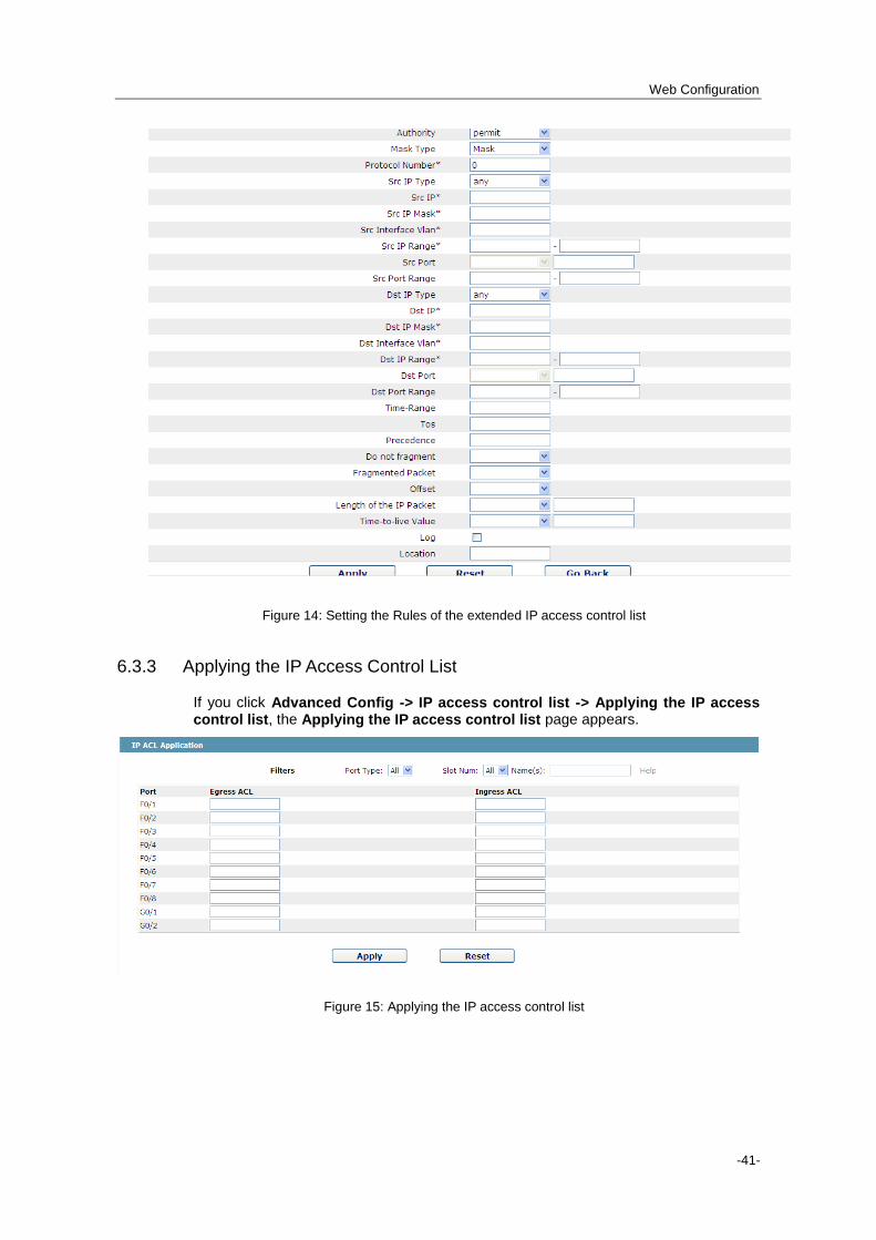
6.3.3 Applying the IP Access Control List
If you click Advanced Config -> IP access control list -> Applying the IP access control list, the Applying the IP access control list page appears.
Figure 15: Applying the IP access control list

Web Configuration
-42-
Chapter 7 Network Management Configuration
Figure 1: Network management configuration list
7.1 SNMP Configuration
If you click Network management Config -> SNMP management in the navigation bar, the SNMP management page appears, as shown in figure 2.
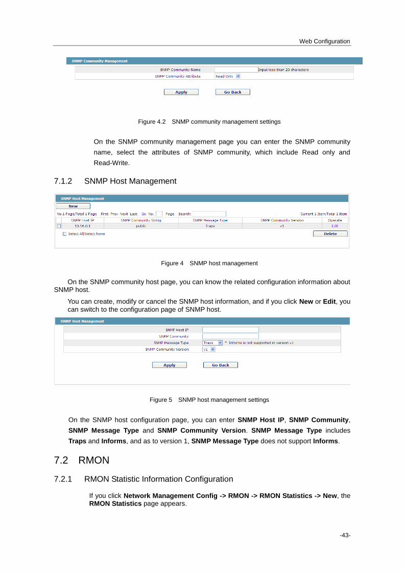
7.1.1 SNMP Community Management
Figure 2 SNMP community management
On the SNMP community management page, you can know the related configuration information about SNMP community.
You can create, modify or cancel the SNMP community information, and if you click New or Edit, you can switch to the configuration page of SNMP community.
Web Configuration
-43-
Figure 4.2 SNMP community management settings
On the SNMP community management page you can enter the SNMP community
name, select the attributes of SNMP community, which include Read only and
Read-Write.
7.1.2 SNMP Host Management
Figure 4 SNMP host management
On the SNMP community host page, you can know the related configuration information about SNMP host.
You can create, modify or cancel the SNMP host information, and if you click New or Edit, you
can switch to the configuration page of SNMP host.
Figure 5 SNMP host management settings
On the SNMP host configuration page, you can enter SNMP Host IP, SNMP Community,
SNMP Message Type and SNMP Community Version. SNMP Message Type includes
Traps and Informs, and as to version 1, SNMP Message Type does not support Informs.
7.2 RMON
7.2.1 RMON Statistic Information Configuration
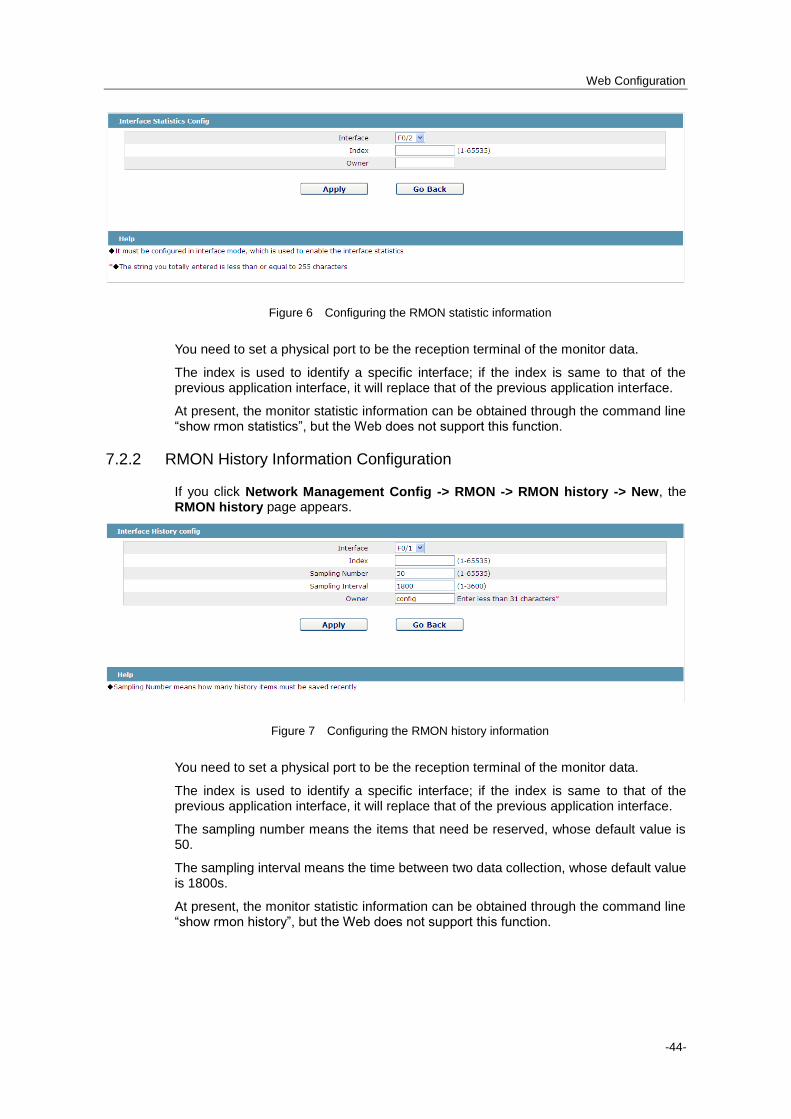
If you click Network Management Config -> RMON -> RMON Statistics -> New, the RMON Statistics page appears.
Web Configuration
-44-
Figure 6 Configuring the RMON statistic information
You need to set a physical port to be the reception terminal of the monitor data.
The index is used to identify a specific interface; if the index is same to that of the previous application interface, it will replace that of the previous application interface.
At present, the monitor statistic information can be obtained through the command line “show rmon statistics”, but the Web does not support this function.
7.2.2 RMON History Information Configuration
If you click Network Management Config -> RMON -> RMON history -> New, the RMON history page appears.
Figure 7 Configuring the RMON history information
You need to set a physical port to be the reception terminal of the monitor data.
The index is used to identify a specific interface; if the index is same to that of the previous application interface, it will replace that of the previous application interface.
The sampling number means the items that need be reserved, whose default value is 50.
The sampling interval means the time between two data collection, whose default value is 1800s.
At present, the monitor statistic information can be obtained through the command line “show rmon history”, but the Web does not support this function.

Web Configuration
-45-
7.2.3 RMON Alarm Information Configuration
If you click Network Management Config -> RMON -> RMON Alarm -> New, the RMON Alarm page appears.
Figure 8 Configuring the RMON alarm information
The index is used to identify a specific alarm information; if the index is same to the previously applied index, it will replace the previous one.
The MIB node corresponds to OID.
If the alarm type is absolute, the value of the MIB object will be directly minitored; if the alarm type is delta, the change of the value of the MIB object in two sampling will be
monitored.
When the monitored MIB object reaches or exceeds the rising threshold, the event corresponding to the index of the rising event will be triggered.
When the monitored MIB object reaches or exceeds the falling threshold, the event corresponding to the index of the falling event will be triggered.
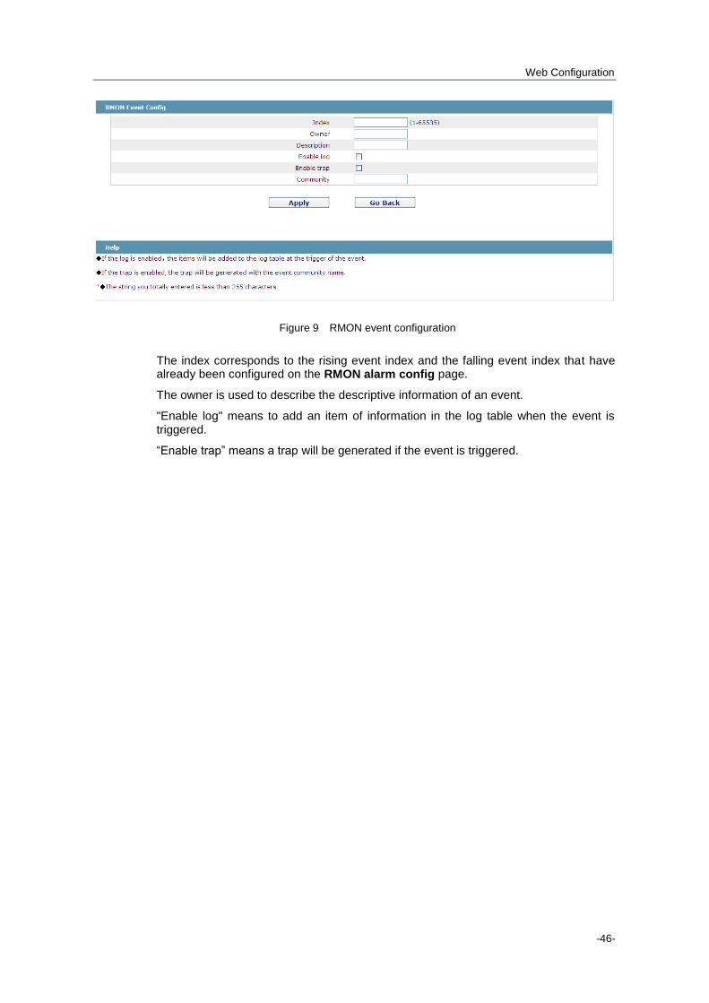
7.2.4 RMON Event Configuration
If you click Network Management Config -> RMON -> RMON Event -> New, the RMON event page appears.
Web Configuration
-46-
Figure 9 RMON event configuration
The index corresponds to the rising event index and the falling event index that have already been configured on the RMON alarm config page.
The owner is used to describe the descriptive information of an event.
"Enable log" means to add an item of information in the log table when the event is triggered.
“Enable trap” means a trap will be generated if the event is triggered.

Web Configuration
-47-
Chapter 8 Diagnosis Tools
Figure 1: Diagnosis tool list
8.1 Ping
8.1.1 Ping
If you click Diagnosis Tools -> Ping, the Ping page appears.
Figure 2 Ping
Ping is used to test whether the switch connects other devices.
If a Ping test need be conducted, please enter an IP address in the “Destination address” textbox, such as the IP address of your PC, and then click the “PING” button.

Web Configuration
-48-
If the switch connects your entered address, the device can promptly return a test result to you; if not, the device will take a little more time to return the test result.
“Source IP address” is used to set the source IP address which is carried in the Ping packet.
“Size of the PING packet” is used to set the length of the Ping packet which is transmitted by the device.

Web Configuration
-49-
Chapter 9 System Management
Figure 1 Navigation list of system management
9.1 User Management
9.1.1 User List
If you click System Manage -> User Manage, the User Management page appears.
Figure 2 User list
You can click “New” to create a new user.
To modify the permission or the login password, click “Edit” on the right of the user list.
Note: 1. Please make sure that at least one system administrator exists in the system, so that you can manage the devices through Web. 2. The limited user can only browse the status of the device.

Web Configuration
-50-
9.1.2 Establishing a New User
If you click “New” on the User Management page, the Creating User page appears.
Figure 3 Creating new users
In the “User name” text box, enter a name, which contains letters, numbers and symbols except “?”, “\”, “&”, “#” and the "Space" symbol.
In the “Password” textbox enter a login password, and in the “Confirming password” textbox enter this login password again.
In the “User permission” dropdown box set the user's permission. The “System administrator” user can browse the status of the device and conduct relevant settings, while the limited user can only browse the status of the device.
9.2 Log Management
If you click System Manage -> Log Manage, the Log Management page appears.

Web Configuration
-51-
Figure 4 Log management
If “Enabling the log server” is selected, the device will transmit the log information to the designated server. In this case, you need enter the address of the server in the “Address of the system log server” textbox and select the log's grade in the “Grade of the system log information” dropdown box.
If “Enabling the log buffer” is selected, the device will record the log information to the memory. By logging on to the device through the Console port or Telnet, you can run the command “show log” to browse the logs which are saved on the device. The log information which is saved in the memory will be lost after rebooting. Please enter the size of the buffer area in the “Size of the system log buffer” textbox and select the grade of the cached log in the “Grade of the cache log information” dropdown box.
9.3 Managing the Configuration Files
If you click System Manage -> Configuration file, the Configuration file page
appears.
9.3.1 Exporting the Configuration Information
Figure 5 Exporting the configuration file
The current configuration file can be exported, saved in the disk of PC or in the mobile storage device as the backup file.
To export the configuration file, please click the “Export” button and then select the “Save” option in the pop-up download dialog box.
The default name of the configuration file is “startup-config”, but you are suggested to set it to an easily memorable name.
9.3.2 Importing the Configuration Information
Figure 6 Importing the configuration files
You can import the configuration files from PC to the device and replace the configuration file that is currently being used. For example, by importing the backup configuration files, you can resume the device to its configuration of a previous moment.
Note:
Web Configuration
-52-
1. Please make sure that the imported configuration file has the legal format for the configuration file with illegal format cannot lead to the normal startup of the device. 2. If error occurs during the process of importation, please try it later again, or click the “Save All” button to make the device re-establish the configuration file with the current configuration, avoiding the incomplete file and the abnormality of the device. 3. After the configuration file is imported, if you want to use the imported configuration file immediately, do not click “Save All”, but reboot the device directly.
9.4 Software Management
If you click System Manage -> Software Upgrade, the software management page
appears.
9.4.1 Backing up the IOS Software
Figure 7 Backing up IOS
On this page the currently running software version is displayed. If you want to backup IOS, please click “Backuping IOS”; then on the browser the file download dialog box appears; click “Save” to store the IOS file to the disk of the PC, mobile storage device or other network location.
Note: The default name of the IOS file is “switch.bin”, but you are recommended to modify this name to a name that is apt to be read and found.
9.4.2 Upgrading the IOS Software
Note: 1. Please make sure that your upgraded IOS matches the device type, because the matchable IOS will not lead to the normal startup of the device. 2. The upgrade of IOS probabely takes one to two minutes; when the “updating” button is clicked, the IOS files will be uploaded to the device. 3. If errors occur during upgrade, please do not restart the device or cut off the power of the device, or the device cannot be started. Please try the upgrade again. 4. After the upgrade please save the configuration and then restart the device to run the new IOS.
Web Configuration
-53-
Figure 8 Upgrading the IOS software
The upgraded IOS is always used to solve the already known problems or to perfect a specific function. If you device run normally, do not upgrade your IOS software frequently.
If IOS need be upgraded, please first enter the complete path of the new IOS files in the textbox on the right of “Upgrading IOS”, or click the “Browsing” button and select the new IOS files on your computer, and then click “Updating”.
9.5 Resuming Initial Configuration
If you click System Manage -> Resume Config, the Resuming the original configuration page appears.
Figure 9 Resuming the original configuration
Note: 1. If you click the “Resume” button, the current configuration will be replaced by the original configuration, which will take effect after rebooting. 2. Before rebooting the device still works under the current configuration, and if you click “Save All” at the moment, the current configuration will replace the original configuration. The original configuration, therefore, cannot take effect after rebooting. 3. After the rebooting is done and the original configuration takes effect, the Web access of the device will be automatically started. The address of Vlan 1 is 192.168.0.1/255.255.255.0, and the username and password are both “admin”.
To resume the original configuration, click “Resume” and then reboot the device.
9.6 Rebooting the Device
If you click System Manage -> Reboot Device, the Rebooting page appears.
Figure 10 Rebooting the device
If the device need be rebooted, please first make sure that the modified configuration of the device has already been saved, and then click the “Reboot” button.
9.7 About
If you click System Manage -> Diagnosis Tools, the Diagnosis Tools page appears.

Web Configuration
-54-
Figure 11 About Page