Embed Size (px)
Citation preview

Web-based system for Quality Assurance of Radiation
Oncology equipment and procedures
Sara Gholampourkashi
Master of Science
Medical Physics Unit
McGill University
Montreal, Quebec
July 2013
A thesis submitted to the Faculty of Graduate Studies and Research of McGill
University in partial fulfillment of the requirements of the degree of Master of
Science
© Sara Gholampourkashi, 2013
All rights reserved. This dissertation may not be produced in whole or part by
photocopy or other means, without the permission of the author.

ii
DEDICATION
To my family for all their love, support and motivation which made all of this
possible for me.

iii
ACKNOWLEDGEMENTS
I would like to start by thanking my supervisor Dr. François DeBlois for his
invaluable support throughout my thesis. His guidance and encouragement at all
stages of this project made it a wonderful experience.
I would like to acknowledge Dr. Gabriela Stroian for the many hours spent
carefully discussing and advising on my project, Alban Quénoi for his supports with
respect to several programming aspects of my work as well as Patrice Munger for all
his help and supports on the Pynetdicom python module.
I would also like to thank the Medical Physics team at the Jewish General
Hospital for useful discussions and advice on many topics concerning this work.
I would like to give my special thanks to Dr. Mohammad Vakilian and Dr.
Arman Sarfehnia for introducing me to the rewarding field of Medical Physics.

iv
ABSTRACT
In a radiation therapy department, several periodic (daily, monthly, quarterly,
yearly, etc.) and on-request quality control tests are performed as part of the quality
assurance program. The lack of a commercial solution to unify all these tests in one
single system was the motivation for this project. The goal of this thesis work was to
develop a web-based quality assurance software tool for the radiation oncology
division of the Jewish General Hospital that would be easily expendable and
manageable. The tool that was created allows easy access to the tests through a
simple web interface yet allowing advanced management of user rights, processing
of complex numerical data, warning users through email alerts and reports,
scheduling tests, keeping trends of the test results and providing safe storage for the
collected data.
Our system is based on Drupal, an open source web content management
system. Several customizations were done to the basic Drupal system to adapt it to
our needs: several scripts and specialized modules were used to enter and analyse
collected data (text and images) as well as exchange data with the radiotherapy
electronic medical record database.
In this thesis work we have selected and implemented in our system a limited
collection of quality control tests (9) that are representative of all types of tests that
are performed in a radiotherapy clinic, as a full implementation would be beyond

v
the time frame of this project. They are the bases for a future complete
implementation and can be used as a model for other similar tests. The
implemented tests are now being introduced in the clinic simplifying data entry,
access, and analysis.

vi
ABRÉGÉ
Dans un département de radiothérapie plusieurs tests de contrôle de qualité sont
exécutés de façon périodique (journalière, mensuelle, trimestrielle, annuelle, etc.)
où sur demande dans le cadre du programme d'assurance qualité. L'absence d’une
solution commerciale pour unifier tous ces tests dans un seul système informatique
est la motivation de ce projet. L'objectif de ce travail de thèse était de développer un
outil logiciel web d'assurance qualité pour la division de radio-oncologie de l'Hôpital
général juif qui serait facilement extensible et facile à gérer. L'outil qui a été créé
permet un accès facile à des tests via une interface web simple tout en permettant
une gestion avancée des droits des utilisateurs, du traitement des données
numériques complexes, permet l’envoie d’alertes e-mail et de rapports, la
planification temporelle des tests, l’analyse des tendances des résultats et le stockage
des données recueillies.
Notre système est basé sur un logiciel libre de gestion de contenu, Drupal. Plusieurs
adaptations ont été apportées au système Drupal de base pour l'adapter à nos
besoins: plusieurs scripts et modules spécialisés ont été programmés et utilisés pour
saisir et analyser les données recueillies (texte et images) ainsi que l'échange de
données avec la base de données de dossiers médicaux électroniques de
radiothérapie.

vii
Dans ce travail de thèse, nous avons sélectionné et implémenté dans notre système
une collection limitée de tests de contrôle de qualité (9) qui sont représentatifs de
tous les types de tests qui sont effectués dans une clinique de radiothérapie puisque
la mise en œuvre complète de tous les tests est au-delà du délai de cette projet. Les
tests implémentés peuvent facilement être utilisés comme modèles pour les autres
tests. Les tests présentement implémentés sont en cours d'introduction dans la
clinique et simplifie la saisie, l'accès et l'analyse aux données.
viii
TABLE OF CONTENTS
DEDICATION .................................................................................................. ii
ABSTRACT ................................................................................................... viii
ABRÉGÉ ......................................................................................................... vii
LIST OF TABLES ............................................................................................. x
LIST OF FIGURES ..........................................................................................xi
CHAPTER 1:
Introduction ....................................................................................................... 1
1.1 Quality ................................................................................................ 1
1.2 Quality Assurance/ Quality Control / Quality Audit ........................ 2
1.3 Radiation Therapy ............................................................................. 3
1.3.1 Radiation Therapy Process ............................................................ 4
1.4 Quality in RT ..................................................................................... 6
1.4.1 QA in RT ........................................................................................ 7
1.4.2 General quality standards in RT .................................................... 7
1.4.3 Tolerance/Action level ................................................................... 9
1.4.4 Physical QA .................................................................................... 9
1.4.5 Clinical QA ................................................................................... 17
1.4.6 Quality Audits in RT .................................................................... 19
1.4.7 QA guidelines in RT .................................................................... 19
References ....................................................................................................... 21
CHAPTER 2:
Current practices and innovations in radiation therapy QA .......................... 27
2.1 Commercial QA systems .................................................................. 27
2.2 Ideal QA system ............................................................................... 29
2.3 Rational and objectives for the thesis ............................................. 29
References ....................................................................................................... 31

ix
CHAPTER 3:
Concepts in Content Management and Drupal overview .............................. 32
3.1 Content and Content Management ................................................. 32
3.1.1 A brief history of Content Management ..................................... 33
3.1.2 CMS .............................................................................................. 35
3.1.3 Types of CMS ............................................................................... 36
3.1.4 Benefits of using CMS.................................................................. 37
3.2 Drupal overview ............................................................................... 39
3.2.1 Drupal’s history ............................................................................ 39
3.2.2 Features of Drupal ....................................................................... 40
3.2.3 Drupal’s architecture.................................................................... 45
3.3 Software packages ............................................................................ 47
References ....................................................................................................... 51
CHAPTER 4:
Results and Discussion .................................................................................... 52
4.1 Introduction ..................................................................................... 52
4.2 Implemented QC tests ..................................................................... 54
CHAPTER 5:
Conclusions and Future Work ........................................................................ 85
5.1 Conclusions ...................................................................................... 85
5.2 Future Work ..................................................................................... 86
REFERENCES ............................................................................................... 88

x
LIST OF TABLES
Table Page
Table 1: Major categories of Content Management Systems [1], [2] ..................................... 37
Table 2: Implemented QC tests with their corresponding properties.................................... 55
Table 2 Continued: Implemented QC tests with their corresponding properties ................. 56
Table 3: Comparison of min/max dose diff. between the film and the portal image ............. 83
Table 4: Comparison of FWHM analysis between the film and the portal image. The third
column represents the percentage difference between the value obtained with the portal
imager and the film. ................................................................................................................ 84

xi
LIST OF FIGURES
Figure Page
Fig. 1: Overview of QA analysis tools (Courtesy of Daniel Létourneau) .............................. 28
Fig. 2: Website structure in the 1990s [3] ................................................................................ 33
Fig. 3: Structure of a database-driven website [3] .................................................................. 34
Fig. 5: Powered search results by Drupal [5] .......................................................................... 42
Fig. 6: A Drupal collaborative tool for team projects [5] ....................................................... 43
Fig. 7: User permission interface in Drupal [5] ...................................................................... 44
Fig. 8: Twitter module on Drupal [5] ...................................................................................... 44
Fig. 9: Drupal’s stack between other layers of a website [3] ................................................... 45
Fig. 10: Flowchart to perform image-based QC tests ............................................................. 50
Fig. 11: user login page with username and password text boxes ........................................... 53
Fig. 12: System page after a physicist logged in. It shows the available tests for this role on
the right bar (QA actions) and user account information on the upper left bar (HBekarat).
A linac status menu is also available at the lower left bar to view linacs’ latest status. The
status indicates if the linac is in operational clinical mode..................................................... 54
Figure 13: Plan QA Physics verification report. It contains patient demographics and plan
specific information as well as checked items. ........................................................................ 58
Figure 14: Maintenance sheet report. It contains detailed information ............................... 60
of the problem as well as corrective and verification actions. ................................................ 60
Figure 15: HDR source change report. Details of source information, measurements and
activity updates are comprised in this report. ......................................................................... 62

xii
Figure 16: Photon beam output check report reprinting measurements, calculations and
calibration data ........................................................................................................................ 65
Figure 17: Electron beam output check report representing measurements, calculations and
calibration data ........................................................................................................................ 66
Figure 18: Beam output trend filtered for linac type, ion chamber and date ........................ 67
Figure 19: DLG Measurement test report .............................................................................. 69
Figure 20: Orthovoltage weekly QA report presenting measurements, calculations and
calibration data. ....................................................................................................................... 71
Figure 21: Beam output trend by date for each orthovoltage beam quality. ........................ 72
Figure 22: MLC acceleration test image acquired on the portal imager of a linac. .............. 74
Figure 23: MLC acceleration test results by python script. The acquired image on the
imager with defined ROI’s (top figure). ROI analysis results (bottom figure). .................... 75
Figure 24: Four asymmetric fields of 5 x 5 cm2 ....................................................................... 77
Figure 25: Reconstructed image of the image acquired on the portal imager....................... 78
Figure 26: Image acquired on the radiographic film (scaling is different on both images) ... 78
Figure 27: Jaw junctions’ dose profiles in CU from the portal images analysis; Y2 (upper
left); Y1 (lower left); X2 (upper right); X2 (lower right) ....................................................... 79
Figure 28: Jaw junctions’ dose profile in dose percentage from the film analysis;Y2 (upper
left); Y1 (lower left); X2 (upper right); X2 (lower right) ....................................................... 80
Figure 29: ROI’s at four jaw junctions on the portal image ................................................... 81
Figure 30: Dose profiles in CU for the ROI’s at the four jaw junctions; ROI1, Y2(upper
left); ROI2, Y2(lower left); ROI1, X1(upper right); ROI2, X1(lower right) ........................ 82
Figure 31: Dose profile analysis. Min/max dose difference and FWHM ............................... 83

CHAPTER 1
Introduction
Contents
1.1 Quality ..................................................................................................................... 1
1.2 Quality Assurance/ Quality Control / Quality Audit ................................................ 2
1.3 Radiation Therapy ................................................................................................... 3
1.3.1 Radiation Therapy Process ................................................................................. 4
1.4 Quality in RT ........................................................................................................... 6
1.4.1 QA in RT ............................................................................................................ 7
1.4.2 General quality standards in RT ......................................................................... 7
1.4.3 Tolerance/Action level ........................................................................................ 9
1.4.4 Physical QA ......................................................................................................... 9
1.4.5 Clinical QA ....................................................................................................... 17
1.4.6 Quality Audits in RT......................................................................................... 19
1.4.7 QA guidelines in RT ......................................................................................... 19
1.1 Quality
As described by Pawlicki et al. [1], the very first movements towards quality
started in the early years of the 20th century. In those days, quality was not the main
attention of industries. On the other hand, their major focus was on how to fill the
markets with as much of their products as possible or “mass production”. It was
during the same period that a modern approach that considered quality as a
statistical phenomenon was developed at Bell Telephone laboratories in the United
States. Also, the concept of t-test was introduced first time by William Sealy Gosset,
a chemist working for the Guniess brewry (Dublin, Irland). He applied t-test

2
statistics to monitor the quality of industrial process in the Guiness breweries [42].
Later in 1954, Japanese industries modified this concept of quality and promoted
new quality management tools that evolved their products in such a way that
defeated American products in both price and quality by the late 1970’s. It was then
that quality with the definition that is used nowadays was introduced in the U.S.
industry to induce a new spirit of competitiveness with Japanese products in global
markets.
Quality is a subjective term and there are several interpretations and definitions
for it. According to Peter Drucker [2] “Quality in a product or a service is not what
the supplier puts in. It is what the customer gets out and is willing to pay for”. Phillip
B. Crosby [3] defines quality as “conformance to requirements”. A more integral
definition of quality is given by the American Society of Quality (ASQ) [4]:
“Characteristics of a product or service that bear on its ability to satisfy stated or
implied needs; or a product/ service free of deficiencies”.
1.2 Quality Assurance/ Quality Control / Quality Audit
Quality Assurance (QA) and Quality Control (QC) are very similar concepts as
they both refer to actions that assure the quality of a service or product. The ASQ
[4] defines these terms as below:
“Quality Assurance is all those planned or systematic actions necessary to
provide adequate confidence that a product or service will satisfy given
requirements for quality”.

3
“Quality Control is the operational techniques and activities used to fulfill
requirements of quality”.
Thus, QA and QC both involve preventing systematic errors and making sure
that the quality is satisfactory and is what it should be.
ASQ [4] defines quality audit as “a systematic and independent examination and
evaluation to determine whether quality activities and results comply with planned
arrangements and whether their arrangements are implemented effectively”.
Hence, the role of a quality audit is evaluation of needs to improve or correct
actions and is performed by personnel not directly responsible for the QA/QC.
1.3 Radiation Therapy
Radiation therapy (RT) is the application of high doses of ionizing radiation
with the aim of destroying cancer cells while minimizing damage to normal tissues.
Common modalities of RT that deliver radiation depending on the type and location
of cancer include [5]:
External Beam Radiation Therapy (EBRT): This is the most common type of
radiation therapy. High doses of radiation are used to destroy cancer cells
and shrink the tumor. A large machine directs radiation at the tumor tissue
and to some tissue around it [7]. Various radiation types include [5], [7]:
o Photon therapy
o Electron therapy
o Proton therapy

4
Brachytherapy: In this treatment method, a high radiation dose is delivered
locally to the tumor using a sealed radioactive source such as 137Cs or 192Ir
placed internally at a short distance to the tumor [5]. The source that is also
called implant comes in different sizes and shapes and can be temporary or
permanent [5], [7].
1.3.1 Radiation Therapy Process
Achieving the aforementioned goal of RT needs a number of complex
interrelated tasks. After the disease is diagnosed and initial consultations are done
to acquire as much information as possible about patient’s health and tumour, the
radiation therapy team (including radiation oncologist, physicist, radiation therapist,
etc.) start the planning and therapy phases [6], [7], [8].
The first step in the treatment planning process is patient positioning and
immobilization to establish a patient coordinate system. Radiography, Computed
Tomography (CT scan), Magnetic Resonance Imaging (MRI), Positron Emission
Tomography (PET) or Ultrasound (US) images are acquired and input into the
planning system. In the next step the anatomy is defined and organ contours are
determined on set of images [6], [7], [8]. In reports 50 and 62 of the International
Commission on Radiation Units and Measurements (ICRU), these contours are
defined as following [9]:
- Gross Treatment Volume (GTV): Gross palpable or visible extent and
location of the malignant growth, which consists of primary tumor and
5
metastasis. If the tumor is removed before radiotherapy, then no GTV
can be defined.
- Clinical Treatment Volume (CTV): Tissue volume that contains GTV
and subclinical microscopic disease, which has to be eliminated.
- Planning Treatment Volume (PTV): Geometrical concept that takes into
account the effect of all possible geometrical uncertainties, in order to
ensure that the prescribed dose is delivered to the CTV. It is used for
dose planning and reporting.
- Organs At Risk (OAR): Normal tissues whose radiation sensitivity may
significantly influence the treatment planning or prescribed dose.
Next, a treatment plan consisting of a combination of radiation beams or source
arrangements around the 3D virtual volume of the patient (from the imaging
modalities) is developed using a Treatment Planning System (TPS) that includes
dose calculation algorithms to virtually plan the patient according to the doctor’s
prescription. The best plan is determined through the use of several analysis and
optimization tools such as conformity and uniformity indices and a Dose Volume
Histogram (DVH). Finally, the quantities that define the delivered dose on the
specific treatment units (Monitor Units (MU) for EBRT or source dwell time for
Brachytherapy) are calculated. In EBRT, 1 MU is calibrated to correspond to a
given dose (cGy) under a given geometry; this is referred to as the dose calibration
of the treatment unit. For Brachytherapy the current activity of the source is taken

6
into account to calculate the dwell time corresponding to the desired dose. After all
aspects of the plan are reviewed and approved by the radiation oncologist, plan data
are transferred to the treatment machine to start the therapy phase [6], [7], [8].
1.4 Quality in RT
Radiation therapy is a high-risk procedure that requires continuous attention to
its quality to minimize the risk of possible errors and prevent catastrophic accidents
[10]. To comply with high standard recommendations regarding the accuracy of the
dose to be delivered to the patient is challenging when considering the multistep
process of radiation therapy and the uncertainties in each step. Furthermore, the
increasing complexity of the treatment modalities and processes should not be
neglected [8], [11]. Considering these aspects and remembering that patient is the
main beneficiary of a high-quality treatment service, we realize the importance of
managing the quality of each step to assure optimal patient care during the full
therapy procedure [8], [11], [12].
In Report TG-46 [8] of the American Association of Physicists in Medicine
(AAPM) quality in radiation oncology is defined as “the totality of features or
characteristics of the radiation oncology service that bear on its ability to satisfy the
stated or implied goal of effective patient care”
TG-46 also defines quality assurance in radiation therapy as “all those planned
or systematic actions necessary to provide adequate confidence that the radiation
oncology service will satisfy the given requirements for quality care”.

7
From these definitions, we understand that the ultimate goal of quality
assurance in RT is to ensure that the patient receives an accurate and error-free
treatment during the entire treatment process.
1.4.1 QA in RT
A QA program in radiation therapy needs to be comprehensive in the sense that
it should cover the quality of: (1) administrative aspects (such as taking patient data,
making appointments, follow-up, technique optimization); (2) physical aspects
(products and equipment used) and; (3) clinical aspects (diagnosis, planning and
treatment) of patient care. Moreover, results of the QC tests and their frequency
should be recorded. That information being recorded in time allows trend analysis
of the results as well as studying current status of quality assurance performance of
the RT department [5], [8]. Likewise, resources are another important aspect of a
successful comprehensive QA program. Three types of resources are needed to
ensure a QA procedure is handled successfully [8]:
- Personnel: Radiation oncology physicist and dosimetrist
- Tools: QC test tools and equipment
- Time: Assigned time for QA performance, results review and educational
programs
1.4.2 General quality standards in RT
Several parameters are studied in order to evaluate the quality of a radiation
oncology equipment or process [8], [13], [14]:

8
1. Functionality: This criterion evaluates if a system is working or not. Safety
features of equipment are an example of this category.
2. Reproducibility: The results of a test are compared against previous results
acquired when the equipment was commissioned. An example is the physical
characteristics of the treatment beam.
3. Accuracy: Evaluation of the accuracy of a measurement tells us how much
the measured value is deviated from the defined value of a specific
parameter. For example, the accuracy of the dose delivered to the patient
compared to the calculated dose value.
4. Characterisation and documentation (commissioning): This parameter is
measured in order to characterise the performance of a tool or equipment
before it can be used clinically; such is measurement of the ion collection
efficiency or charge leakage of an ion chamber.
5. Linearity of response: This criterion checks if a specific variable changes
linearly with the change of a dependent parameter. An example is the test of
timer linearity of a Brachytherapy unit.
6. Data transfer and validation: Evaluation of this parameter confirms that the
data transmission processes that include both human and machine
involvement have been performed properly and are error-free.

9
1.4.3 Tolerance/Action level
In order to measure and evaluate the aforementioned parameters, we need to
have Tolerance and Action levels. The Canadian Association of Provincial Cancer
Agencies (CAPCA) defines these terms as the following in its reports [13]:
- Tolerance Level: If the difference between the measured and expected
value is at or below the stated tolerance level for a parameter then no
further action is required for that parameter.
- Action Level: If the difference between the measured value and its
expected or defined value exceeds the action level (often twice the
tolerance level) then an action is required immediately.
Thus, any measurement that exceeds the action level requires immediate action
that includes not using the machine (or stopping the treatment process) and
investigating the problem until it is solved. Measurements that fall between
tolerance and action levels are acceptable until the next daily measurement [12].
1.4.4 Physical QA
Physical QA is the evaluation of the dosimetry, mechanical and imaging
characteristics of the radiation therapy equipment. Even small discrepancies in any
of these characteristics can result into a geometrical (such as a beam modifier eg.
collimator or jaw) and dosimetric (like dose calculations) inaccuracy in the dose
delivered to the patient. Gradual wear of the RT equipment and sudden
malfunctions - that might be the result of a failure in the performance of their

10
components - could cause serious deviations in the physical parameters from the
values established during the commissioning of the device. To avoid such
performance deficiencies, two essential QA procedures on the RT machines and
devices are recommended [8], [14]:
i. Periodic/Scheduled QA: This QA program is scheduled on daily, weekly,
monthly and annual periods to ensure the accuracy of the performance
parameters of the equipment.
ii. Unscheduled QA: This is a preventive and maintenance QA program and is
performed following the breakdown/repair of equipment.
As mentioned in the AAPM TG-46 report [8], daily tests are done on
parameters that have a major impact on patient dose, patient positioning and safety
features. Monthly tests include those with lower probability of changing or affecting
the above features. Weekly tests are rarely recommended and annual tests normally
consist of a full calibration of the equipment [8], [15].
As mentioned above, physical QA includes the QA of dosimetry, radiation
therapy and imaging equipment. The Quality Assurance aspect of each group of
equipment is described in more details in the following sections.
1.4.4.1 Dosimetry equipment
The QA of dosimetry equipment is a very important component of the physical
aspect of any quality assurance program in RT as such equipment plays a vital role
in the determination of absorbed dose. The purpose of this QA is to evaluate the

11
operational characteristics of a dosimetry instrument to ensure that the treatment
unit continues to maintain calibration over its time. Thus, apart from the
commissioning of the device that is done at time of purchase, periodic recalibration
or constancy checks are performed. Below is a list of measurement and dosimetry
devices [8], [13], [14], [16]:
1. Devices for reference dosimetry: Ionization chambers and electrometers
2. Devices for relative dosimetry: Ionization chambers, diodes, TLD and film
3. Basic measurement devices: thermometer, barometer, ruler, etc.
4. Automated beam scanning devices: water tank scanners and software
5. QA devices: Ionization chamber, diode array and their software
6. Phantoms
1.4.4.2 Radiation Therapy equipment
Three parameters are tested in a QA program for these equipment [14]:
- Dosimetry (output, beam profile, energy constancy, …)
- Mechanical (light/radiation field coincidence, isocentre, jaws, MLC, …)
- Safety (door interlock, audiovisual monitors, …)
A sample of radiation therapy equipment and some typical QA tests are
reviewed in this section [8], [13], [14], [16]:
1. Cobalt therapy units: Co-60 units are not commonly used these days. The
main components of a teletherapy unit are: radioactive source such as Co-60;
source housing; gantry and stand; patient support; and machine console. The

12
radioactive source is a gamma ray source used in EBRT [18]. A complete list
of periodically performed quality control tests that are part of the QA
program for this equipment can be found in AAPM TG-46 [8] and CAPCA
[17] reports.
2. Medical Linear Accelerators (linacs) and Multileaf Collimators: linacs
accelerate electrons to kinetic energies from 4 to 25 MeV. Some linacs
provide x-rays only in the low megavoltage range (4 MV to 10 MV) while
others provide both x-rays and electrons at various megavoltage energies. A
typical modern high-energy linac will provide two or three photon energies in
the range 4 to 10 MeV and on in the range 12 to 25 MeV as well as several
electron energies in the range 4 to 22 MeV [18]. Linacs are currently the
most commonly used treatment modalities in radiation therapy. In recent
years, linacs have become more complex integrated machines with the advent
of technologies such as EPID (Electronic Portal Imaging Device), OBI (On-
Board Imaging), 4D management, VMAT (Volumetric-Modulated Arc
Therapy), etc. This naturally increases the number of quality control tests for
these machines. Quality assurance guidelines for linacs are described in
AAPM TG-46 [8], AAPM TG-142 [19] and the newly-created Canadian
Partnership for Quality Radiotherapy (CPQR) reports [20]. In addition,
every manufacturer has recommended guidelines and test procedures that
should be followed to ensure proper performance of the machine.

13
A relatively recent technological addition to linacs is the Multileaf
Collimator (MLC), a computer-controlled device that consists of several
pairs of narrow, closely joined tungsten leaves. MLCs are used as beam
modifiers to shape irregular fields. A quality assurance program must include
MLC control tests to ensure safe mechanical operation (motion of leaves,
interlocks for the leaves, etc.), dosimetric compliance (transmission of the
leaves, leakage between the leaves, etc.), and proper software (data transfer
between the TPS and the MLC, etc.) aspects [18]. Details and procedures to
execute the performance tests of the MLC are described in AAPM TG-142
[19], CPQR [20], and AAPM No.72 [21]. Moreover, Galvin [22] has provided
a comparative quality control guideline between MLCc manufactured by
Elekta (Stockholm, Sweden) and Varian (Palo Alto, CA).
3. Kilovoltage X-ray radiotherapy machines: Kilovoltage (40-300 kV) x-ray
beams are used in radiation therapy for treatment of skin lesions (superficial
x-ray: 40-100 kV) and shallow tumours (orthovoltage x-ray: 100-300 kV).
They are generally less complex treatment machines and this leads to a
simpler quality assurance program in comparison to a linac. The QA
program of kilovoltage machines mainly involves the evaluation of dosimetry
parameters like output checks and beam profiles. Nevertheless, a few tests
are also performed for the purpose of quality control of mechanical and
safety features of the unit. CPQR [23] covers QA details of kilovoltage unit

14
and dosimetry. Moreover, QA procedures are available through the AAPM
TG-61 [24] report.
4. Stereotactic Radiosurgery (SRS): This is a complex technique that delivers a
very-high prescribed dose of ionizing radiation to stereotactically localized
benign or malignant lesions in the brain and for the treatment of vascular
malformations or other functional conditions. Several techniques are used to
deliver SRS treeatments [18], [24]:
o Linac-based which uses a linac with tight mechanical and electrical
tolerances such as a remotely controlled motorized table and a micro
MLC. A rigid frame is used in this technique to fix the patients head
for the purpose of precise beam delivery.
o Gamma knife (Elekta, Stockholm, Sweden) that consists of a helmet
containing 201 Co-60 sources and a collimator that directs the beams
to a focal point.
o Cyber knife (Accuray, Sunnyvale, CA) that is a miniature linac on a
robotic arm and allows frameless radiosurgery. It uses and on-line
imaging system for finding the exact position of the target by tracking
the patient’s position continuously.
The quality assurance for radiosurgery comprises: 1. The basic quality
assurance protocol dealing with the accuracy of the target localization, dose
delivery, etc.; 2. The treatment QA protocol covering the calibration and

15
preparation of equipment before each SRS treatment delivery, and 3. Patient
specific QA which will be described in more detail in section 1.4.5. Also,
details on SRS quality assurance protocols and procedures are available
through CAPCA [24] reports on SRS and AAPM report No.54 [25]. A
separate report published by the AAPM (as Task Group 135) covers the
recommendations on quality control and dosimetric verification for
Cyberknife [26].
5. Brachytherapy remote afterloader: Brachytherapy is the placement of
encapsulated radioactive sources at a short distance from the target volume
(i.e. tumour). The sources are either low dose rate (LDR, 0.4-2 Gy/h) or high
dose rate (HDR, >12 Gy/h). In order to reduce or even eliminate the
radiation exposure to the staff, remote afterloading equipment is operated
remotely from a central room. Brachytherapy plays an important role in the
treatment of many cancers such as GYN, prostate, breast, head and neck and
etc. Quality assurance tests for remote afterloaders should anticipate possible
failures of the system. A standard QA procedure for a remote afterloader
includes testing the accuracy of the source selection as well as the spatial
positioning and control of treatment duration. Moreover, safety features
should be included [27], [28]. Details are provided in a CPQR report on the
QA of brachytherapy remote afterloaders [28] and the AAPM TG- 56 [27].
16
1.4.4.3 Imaging equipment
The main purpose of physical QA for imaging equipment used in RT is to test:
1) image quality characteristics such as contrast, resolution, and SNR and 2) output
and dose control 3) mechanical and geometrical accuracy.
Imaging equipment reviewed in this section includes on-board imagers and
simulators. There are also diagnostic imagers like MRI and PET and details on their
quality control can be found in various AAPM Task Groups [40], [41].
1. Conventional simulators and CT simulators: A simulator consists of a
diagnostic x-ray tube mounted on a machine that mimics all the mechanical
features of a megavoltage machine. It is used to simulate the patient’s
position, shape and anatomy relative to the RT machine and isocentre [18],
[30]. A CT simulator uses a helical CT to [18], [31]: 1) Acquire a CT image,
2) Transfer the image to the RT planning software, and 3) Marking patient’s
reference point to transfer the coordinates of the tumour isocentre to the
surface of the patient.
From the above functionality of simulators we understand that they
should be subject to the same mechanical/geometric and safety checks as
Linacs as well as image quality tests [8], [14]. QA checks for conventional
simulators are tabulated in CAPCA quality report for conventional
simulators [30]. Moreover, CAPCA report on CT-simulators [31] covers the
QA checks for CT simulators.

17
2. On-Board Imagers: This is one of the modalities of Image Guided
Radiotherapy (IGRT) that is used during treatment to monitor and adjust
radiotherapy delivery. A kV X-ray source is used in on-board imagers [32].
Yoo et al. [33] provide a quality assurance program for On-Board Imagers
(OBI).
3. Electronic Portal Imaging Devices: This is another modality of IGRT and is
an effective way to verify the geometric treatment accuracy in order to
reduce setup errors in external beam RT. Instructions to perform quality
control tests for EPID are provided in CAPCA [34] and AAPM-TG 58 [29]
reports.
1.4.5 Clinical QA
Clinical QA includes the quality checks for the radiation therapy treatment
planning and consists of quality control of general and patient specific/new patient
treatment planning process and Treatment Planning Systems (TPS). These quality
control procedures are usually tailored to the complexity and functionality of
treatment planning procedures and systems in different clinics.
1. Patient specific/new patient QA: Due to the complex procedure, high dose
delivery and precision in techniques such as conformal 3D (IMRT, Rapid-
Arc, ...) and SRS a patient specific dosimetry and treatment delivery quality
control system is designed to validate the feasibility and accuracy of dose
delivery prior to the first treatment fraction. Performing patient specific QA

18
is of high importance and neglecting these checks could result in non-
reversible issues ranging from minor performance to patient death [35]. New
patient QA is a peer review among the radiation therapy team and consists
of the following components [8]:
I. New patient planning conference: Medical history, diagnostic
findings, tumour staging, and treatment strategy
II. Chart/film review: Patient ID, initial physical and clinical
information, treatment planning, clinical assessment during
treatment, treatment summary and follow-up
III. Film review: Assessment of radiation field position and target
volume
2. Treatment Planning System: A TPS comprises the hardware and software to
input patient and simulation data, define target volumes and organs at risk
and perform dose calculations and optimization and finally output the results
of calculations. Quality control of a TPS has two components: 1) Quality
checks for the dose calculation algorithms in use to assure that the correct
algorithm is used and clinically accurate dosimetry predictions are generated,
and 2) quality test of the software and hardware system to prevent any
malfunctions of the system [36]. Also, quality control checks provided by TPS
vendors must be performed to ensure the functionality of the system.

19
More details on RT clinical QA is available through CPQR report on Treatment
Planning Systems [36] and AAPM reports on different RT techniques like IMRT
(Intensity Modulated Radiation Therapy)[37] and SRS [25], [26]. However, as
mentioned at the beginning of this section, patient specific QA is inspired from
various particular guidelines but each clinic customizes its program based on its
specific needs and policies.
1.4.6 Quality Audits in RT
A fundamental step in any QA program are the audits that should be performed
by independent external organizations (national or international) at a frequency
stated in the policies and procedures manual. The main purpose of quality audits is
to ensure that components of the quality assurance program in a radiation therapy
department are performed appropriately. The feedback from the process is used to
improve the quality generally. In other words, it is a detailed and careful review of
the RT department’s QA program and includes checks of dosimetry systems, safety
tests (electrical, mechanical, etc.), tests of TPSs, and a review of clinical dosimetry
records [8], [18], [38].
1.4.7 QA guidelines in RT
Many national and international bodies have developed various guidelines and
protocols on the QA of radiation therapy equipment and procedures. AAPM,
CAPCA and CPQR provide comprehensive guidelines on the QA of equipment and
treatment planning in the United States and Canada respectively. CPQR has taken

20
the responsibility of CAPCA and publishes updated versions of documents
previously provided by CAPCA. QA of new RT technologies are mostly covered by
CAPCA and CPQR. In Europe, the European Society for Therapeutic Radiology
and Oncology (ESTRO) [11] and at the international level, the International
Atomic Energy Agency (IAEA)/ World Health Organization (WHO) provide
guidelines on the quality assurance/quality audit of radiation therapy [39]. Other
organizations like the American Society for Therapeutic Radiology and Oncology
(ASTRO, Fairfax, VA), the Radiation Therapy Oncology Group (RTOG,
Philadelphia, PA) and the Quality Assurance Review Center (QARC, Lincoln, RI)
perform studies at the national level in order to help the evaluation and upgrade of
the radiation therapy services quality and quality control.

21
References
[1] Todd Pawlicki, and Aron J. Mundt. Quality in radiation oncology. Med. Phys. 34
(5), 2007.
[2] Druker, Peter. Innovation and entrepreneurship practices and principals. Harper
& Raw, 1985.
[3] Crosby, Phillip. Quality is free. McGraw-Hill, New York, 1979.
[4] American Society of Quality: http://asq.org
[5] Faiz, M. Khan. The physics of Radiotherapy. Lippincott Williams & Wilkins,
third edition, 2003.
[6] American Association of Physicists in Medicine. AAPM TG-53 Report: Quality
Assurance for clinical radiotherapy treatment planning, 1998.
[7] Canadian Cancer Society. Cancer Canada: Cancer treatment
http://www.cancer.ca/Quebec/About%20cancer/Treatment/Radiation/External%
20beam%20radiation%20therapy.aspx?sc_lang=en&r=1
[8] American Association of Physicists in Medicine. AAPM TG-46 Report:
Comprehensive QA for radiation oncology, 1994.

22
[9] International Commission on Radiation Units and Measurements. ICRU report
62: Prescribing, recording and reporting photon beam therapy (Supplement to
ICRU report 50)
[10] Peter Dixon, Brian O’sallivan. Radiotherapy Quality Assurance: Time for
everyone to take it seriously. European Journal of cancer. 39 (4), 2003.
[11] European Society for Therapeutic Radiology and Oncology. ESTRO:
Recommendations for a Quality Assurance programme in External
Radiotherapy, First edition, 1995.
[12] Thwaits DI., Mijnhaer BJ., and Mills JA. Quality Assurance of External Beam
Radiotherapy in radiation oncology physics: A handbook for teachers and
students, E.B. Podgorsak (editor), IAEA, Vienna, Austria, 2005.
[13] Canadian Association of Provincial Cancer Agencies. CAPCA, Standards for
Quality Control at Canadian Radiation Treatment Centres: Major dosimetry
equipment, 2007.
[14] American Association of Physicists in Medicine. AAPM TG-13 Report:
Physical aspects of Quality Assurance in Radiation Therapy, 1994.
[15] L.W. Brady, H.P. Heilmann, M. Molls, and C. Nieder. Technical basis of
Radiation Therpay: Practical clinical applications, Seymour H. Levitt et al.
(editors), fifth edition, 2012.

23
[16] Canadian Partnership for Quality Radiotherapy. CPQR, Technical Quality
Control guidelines for Canadian Radiation Treatment centres: Major dosimetry
equipment, 2012.
[17] Canadian Association of Provincial Cancer Agencies. CAPCA, Standards for
Quality Control at Canadian Radiation Treatment Centres: Co-60 Teletherapy
unit, 2006.
[18] E.B. Podgorsak, Treatment machines for External Beam Radiotherapy: A
handbook for teachers and students, E.B. Podgorsak (editor), IAEA, Vienna,
Austria, 2005.
[19] American Association of Physicists in Medicine. AAPM TG-142 Report:
Quality Assurance of medical accelerator, 2009.
[20] Canadian Partnership for Quality Radiotherapy. CPQR, Technical Quality
Control guidelines for Canadian Radiation Treatment centres: Medical Linear
Accelerators and Multileaf Collimators, 2012.
[21] American Association of Physicists in Medicine. AAPM TG-50 Report: Basic
applications of Multileaf Collimators, 2001.
[22] James M. Galvinn, The Multileaf Collimator-A complete guide, 1999.

24
[23] Canadian Partnership for Quality Radiotherapy. CPQR, Technical Quality
Control guidelines for Canadian Radiation Treatment centres: Kilovoltage
X-ray radiotherapy machines, 2012.
[24] Canadian Association of Provincial Cancer Agencies. CAPCA, Standards for
Quality Control at Canadian Radiation Treatment Centres: Stereotactic
Radiosurgery/Radiation Therapy, 2006.
[25] American Association of Physicists in Medicine. AAPM Report No. 54:
Stereotactic Radiosurgery, 1995.
[26] American Association of Physicists in Medicine. AAPM TG-135 Report:
Quality Assurance for robotic radiosurgery, 2011.
[27] American Association of Physicists in Medicine. AAPM TG-56 Report: Code
of practice for brachytherapy physics, 1997.
[28] Canadian Partnership for Quality Radiotherapy. CPQR, Technical Quality
Control guidelines for Canadian Radiation Treatment centres: Brachytherapy
remote afterloaders, 2012.
[29] American Association of Physicists in Medicine. AAPM TG-58 Report: Clinical
use of Electronic Portal Imaging, 2001.

25
[30] Canadian Association of Provincial Cancer Agencies. CAPCA, Standards for
Quality Control at Canadian Radiation Treatment Centres: Simulators, 2005.
[31] Canadian Association of Provincial Cancer Agencies. CAPCA, Standards for
Quality Control at Canadian Radiation Treatment Centres: CT Simulators,
2007.
[32] E. Schreibemann, E. Elder, and T. Fox, Automated Quality Assurance for
Image-Guided Radiation Therapy, Journal of Applied Clinical Medical Physics.
10 (1), 2009.
[33] S. Yoo, T. Pawlicki et al., A quality assurance program for the on-board imager,
The International Journal of Medical physics Research and Practice. 33 (11),
2006.
[34] Canadian Association of Provincial Cancer Agencies. CAPCA, Standards for
Quality Control at Canadian Radiation Treatment Centres: EPID, 2005.
[35] N. Aguzaryan, T. Solberg, and J. J. DeMarco, Patient Specific Quality
Assurance for delivery of Intensity Modulated Radiotherapy, Journal of
Applied Clinical Medical Physics. 4 (1), 2003.
[36] Canadian Partnership for Quality Radiotherapy. CPQR, Technical Quality
Control guidelines for Canadian Radiation Treatment centres: Treatment
Planning Systems, 2012.

26
[37] American Association of Physicists in Medicine. Report of the IMRT
subcommittee of the AAPM radiation therapy committee: Guidance document
on delivery, treatment planning and clinical implementation of IMRT, 2003.
[38] J. Izewska, H. Svensson, and G. Ibbott, Worldwide Quality Assurance networks
for radiotherapy dosimetry, 2003.
[39] IAEA, Quality Assurance in Radiation Therapy, Vienna, Austria, 1997.
[40] American Association of Physicists in Medicine. AAPM Report No. 100:
Acceptance Testing and Quality Assurance Procedures for Magnetic Resonance
Imaging Facilities, 2010.
[41] American Association of Physicists in Medicine. AAPM TG-126 Report: PET
and PET/CT Acceptance Testing and Quality, 2009.
[42] J. F. Box, Guiness, Gosset, Fisher, and small samples, Statistical Science. Vol. 2,
No. 1, 1987.

27
CHAPTER 2
Current practices and innovations in radiation therapy QA
Contents
2.1 Commercial QA systems ........................................................................................ 27
2.2 Ideal QA system ..................................................................................................... 29
2.3 Rational and objectives for the thesis .................................................................... 29
2.1 Commercial QA systems
As mentioned in the previous chapter, there are several quality control checks
that need to be performed either periodically or case-based in a radiation therapy
centre. Thus, the use of an information system (IS) that would record, log, schedule
and to some extent manage and regroup all quality control tests would greatly
simplify and quicken the QA process in radiation therapy and could be truly
efficient from several aspects. Below is a list of some commercially available QA
systems:
- Argus (Varian, Palo Alto, CA)
- Atlas (Sun Nuclear Corp., Melbourne, FL)
- eQA (Modus, London, ON)
- PIPSpro (Standard Imaging, Middleton, WI)
- QualiMagiQ (Qualiformed, La Roche Sur Yon, France)
- OmniPro Advance (IBA, Louvain-la-Neuve, Belgium)

28
- MLC Soft EPID (PTW, Freiburg, Germany)
- Leafline MLC QA (Civco, Kalona, Iowa)
Quality Assurance systems can be classified in two categories based on their
functionalities (D. Létourneau, personal communication, Jun 27, 2012):
I. Generic and basic analysis (Argus and Atlas)
II. Task-specific and full analysis (eQA, PIPSpro, …)
Group I, generally consists of tests such as checklists, security checks, etc.
Whereas group II refers to more specific equipment tests such as specific beam
modifier measurements (MLC, wedges, jaws), machine positioning tolerances,
image analysis tests, etc.
Fig. 1 gives an overview of the number of tests versus the system used for QA
data analysis.
Fig. 1: Overview of QA analysis tools (Courtesy of Daniel Létourneau).
There were some recent attempts of developing QA analysis tools that would
include both generic and task specific tests. Such attempts include commercial
Group I
Group II
# T
ests
Analysis tools

29
products such as the new version of ATLAS QA from Sun Nuclear and a
collaborative academic QA system called AQUA, developed at the University of
Toronto [1].
2.2 Ideal QA system
The ideal radiation therapy quality assurance system would include the following
features:
1. Automated analysis of the data
2. Accurate, precise and sensitive
3. Fast and user friendly
4. Powerful in report generation and keeping trends
5. Centralized and searchable database
6. Compatible with the departmental electronic medical record systems
7. Accessible to all desktop computers and mobile devices
2.3 Rational and objectives for the thesis
The motivation for this project is to develop a software QA tool for our
radiation therapy department at the Montreal Jewish General Hospital (JGH). This
tool should ease the storage and retrieval of QA data and should allow trend
keeping and report generation. It should include scheduling, managing and
supervising workflows through the use of email alerts and electronic calendars. Such
a system should use a centralized database and ideally be web-based to allow wide
access to QA data, analysis and reports (desktop computer, smart phone, tablets,
30
etc.). This tool should replace Excel files (Microsoft, Redmond, WA), paper forms
and records as well as some highly specific QA software tools. Moreover, the tool
should permit data transfer from the Electronic Medical Record (EMR) and
Treatment Planning System (TPS) of our radiation oncology department. This
transfer would minimize the manual data entry and possibility of errors on the QA
tool side.
An EMR is a computer-based medical record system used by health care
professionals and comprises a database containing patients’ information such as
demographic, medical and drug history, and diagnostic information. It also contains
scheduling information and is often integrated with other software that manages
other clinical activities [2], [3]. At the JGH, we use the ARIA EMR system (ARIA
V. 10, Varian, Palo Alto, CA). ARIA is a comprehensive oncology information
system provided by Varian Medical Systems. ARIA combines radiation, medical and
surgical oncology information and allows the radiation oncology team to oversee all
aspects of oncology care of their patient from initial diagnosis through post-
treatment follow-ups [4].
As defined by AAPM- TG 53 report [5], A Radiotherapy TPS is a
“computerized program that helps the treatment planner and physician define the
target volume, determine beam directions and shapes, calculate the associated dose
distribution, and evaluate that dose distribution”. At the JGH we use the Eclipse
TPS (Eclipse V.10, Varian, Palo Alto, CA).

31
References
[1] D. Létourneau, A. McNiven, DA. Jaffray. Multicenter collaborative Quality
Assurance program for the province of Ontario: first-year results. International
journal of radiation oncology biology physics. 86(1), 2003.
[2] Canada Health Infoway: EMR
https://www.infoway-inforout.ca/index.php/programs-services/certification-
services/what-infoway-certifies/emr
[3] Ministry of Health of British Columbia: e-Health – Faster, safer, better health
care (EMR)
http://www.health.gov.bc.ca/ehealth/emr.html
[4] Varian medical systems. ARIA overview
http://www.varian.com/us/oncology/radiation_oncology/aria/
[5] American Association of Physicists in Medicine. AAPM TG-53 Report: Quality
Assurance for clinical radiotherapy treatment planning, 1998.

32
CHAPTER 3
Concepts in Content Management and Drupal overview
Contents
3.1 Content and Content Management........................................................................ 32
3.1.1 A brief history of Content Management........................................................... 33
3.1.2 CMS .................................................................................................................. 35
3.1.3 Types of CMS .................................................................................................... 36
3.1.4 Benefits of using CMS ...................................................................................... 37
3.2 Drupal overview ..................................................................................................... 39
3.2.1 Drupal’s history ................................................................................................. 39
3.2.2 Features of Drupal ............................................................................................ 40
3.2.3 Drupal’s architecture ........................................................................................ 45
3.3 Software packages .................................................................................................. 47
3.1 Content and Content Management
Definition of content can vary depending on the context in which it is in use. For
example, content of a printed material such as books, user guides, and business
documents is text and graphics. For digital publications such as web sites and
e-books, content is any type or unit of digital information. It includes text, graphics,
video, sounds, etc. In other words, it could be anything that is likely to be managed
in electronic format [1], [2].
Content Management is effective management of the aforementioned electronic
content in such a way that it would be stored as organized and consolidated pieces of
content. This is achievable by combining rules, process and/or workflows. This
organized content can be used several times in different digital publications [1], [2].

33
3.1.1 A brief history of Content Management
Before we take a closer look at Content Management and Content Management
Systems as they work today, we will briefly review the history of how the content of a
website was managed before the creation of Content Management Systems.
In the 1990s, web pages consisted only of simple text files (like index.html,
news.html, and so on) that linked to each other through the Hypertext Markup
Language (HTML) and could also contain media. Known as websites, these files
were bundled into folders on servers on the Internet and were viewable by anyone
through a web browser [3]. Figure 2 is a structure diagram of such a website.
Fig. 2: Website structure in the 1990s [3].
This system works relatively well however, adding content to the website is a
tedious task as it requires lots of manual operations.
Generated by CamScanner from intsig.com

34
To facilitate content management, two changes were introduced to web servers
[3]:
1. The use of scripts and Common Gateway Interface (CGI) to simplify
updating the content of the web page. Special tags were added to HTML files
to tell the web server to catch the content of another file – that stored all the
updates - and include it in the current web page as if it were part of the
HTML file.
2. The use of databases to store pieces of similar content. Thus, instead of
storing each content as a separate HTML file, it was tracked down and
retrieved from the database and sent back to the website to be displayed.
Figure 3 shows the structure of a database-driven website.
Fig. 3: Structure of a database-driven website [3].
Although all these changes solved some problems, challenges like managing
contents of large sites and dealing with dynamic contents still remained unsolved.
Generated by CamScanner from intsig.com

35
It was at this stage that Content Management Systems emerged and provided
the necessary tools and mechanisms to enable web servers to manage dynamically
complex content.
3.1.2 CMS
In simple words, a Content Management System or CMS is a system used to
manage the content of a web site. More technically, CMS can be defined as the
following [2]:
“A CMS is a tool that enables a variety of technical (centralised) and non
technical (de-centralised) staff to create, edit, manage and finally publish a variety
of content in a number of formats such as text, graphics, video, documents, etc.,
whilst being constrained by a centralised set of rules, process and workflows that
ensure coherent, validated electronic content”.
A CMS consists of two major elements [4]:
1. Content Management Application (CMA): This element allows the
content manager or author of the web site to create, modify and remove
the contents of a website without having any knowledge of HTML.
2. Content Delivery Application (CDA): This element works as the
compiler of the created information through CMA, to update the
website.

36
3.1.3 Types of CMS
Although features of different CMS systems vary, they are common in features
such as web-based publishing, format management, revision control, indexing,
search and retrieval [4]. They provide tools for organizations that might produce one
or some of the following contents [1], [4]:
- Technical documentation (parts catalogues, user’s manuals)
- Reference materials (encyclopaedia, dictionary)
- Testing and training materials (e-learning programs, testing booklets)
- Marketing and educational materials (brochures, promotional flyers, one-
to-one marketing)
Based on the different features and capabilities of a CMS and considering the
type of content an organization might publish, five major types of CMS’s are defined
that are categorized in table 1 next page [1], [2].

37
Type of CMS Purpose
Web Content Management (WCM)
Managing and delivering content to
websites
Digital Asset Management (DAM)
Managing graphics and multimedia and
their corresponding metadata, no text
Document Management (DM)
Managing whole document rather than
the actual content itself
Enterprise Content Management
(ECM)
Managing all aspects of content within
an organization (i.e., emails, business
documents, etc.) and is scalable for use
throughout the entire enterprise
Component Content Management
(CCM) or XML Content Management
(XML CM)
Managing content at the component
level and storing it only one time as a single
source for maximum content reuse and
delivery to multiple medial channels (i.e.,
print, PDF, etc.)
Table 1: Major categories of Content Management Systems [1], [2].
3.1.4 Benefits of using a CMS
A major benefit when using a CMS to manage (store and interact) with large
amounts of data is having a better integration and organization of the content. The
CMS offers an easy solution to track and adapt changes to the structure of the data
38
while maintaining a consistent and optimized database. The benefits provided by a
CMS to any organization are [1]:
- Centralized and shared content: Content is concentrated and integrated
into a powerful repository that facilitates content sharing among co-
workers. This prevents creation of duplicate content in different formats.
- Accurate content: Content is stored one time but any changes made to is
tracked by the CMS to make sure that all appropriate links and instances
are updated and remain consistent. Hence, individually updated versions
of one document would not exist anymore.
- Secure content: User permissions are assigned, so only authorized people
can access certain contents and security threats no more exist.
- Shorter editorial cycles: Automated alerts can be assigned to users’ daily
tasks and due dates. This could help save the time to editorial tasks and
monitoring of responsibilities.
- Quick creation of new publications: Creation of new publication can
happen within a few minutes as previously written contents can be
searched, retrieved and reused.
- Timely delivery of publications: As the single-source content is updated
once and repurposed for multiple media channels periodically, separate
files are not needed for print, web, and Protable Document Format

39
(PDF) versions of the content. Thus time to update and publish content is
saved.
- Lower translation costs: A CMS has full Unicode (Unicode.org) support
that allows “chunks” of updated content to be translated instead of the
entire document and thus is less confusing and costly.
3.2 Drupal overview
Drupal [5] is an open source CMS used by hundreds of thousands of
organizations to build customized websites to their precise needs. To maintain a
Drupal website, no manual change of source code is required; maintenance can be
done through online forms [3], [5]. As Drupal is open source it is free to download
and use. It is distributed under the terms of GNU General Public License (GPL)[5].
3.2.1 Drupal’s history
Dries Buytaert (a student at university of Antwerp, Belgium) started to develop
Drupal in 1999. Initially, Drupal was a “Message Board” system that was shared on
the university Local Area Network (LAN) with the purpose of communication and
information exchange among his colleagues. After he graduated he moved this
“Message Board” to a live website on the Internet [5].
It was around 2001 that Buytaert realized the growing interests for his online
“Message Board” and decided to distribute his software to the community as an
open source distribution for people to experiment on their own and add new
features to it. It was at this point that his local “Message Board” became “Drupal”.
40
Since that day, many additional modules have been developed for Drupal to extend
its capabilities. The interest for Drupal is constantly growing with an active
community of over 650,000 users and 10,000 developers in 228 countries [5].
3.2.2 Features of Drupal
As a CMS, Drupal provides a number of features that eases the creation and
management of websites. These features have highly increased the popularity of
Drupal in such a way that not only small businesses but also several global
corporations use Drupal widely as their publishing platform.
Below are some examples of large companies that use Drupal [3], [5]:
- The Economist, Popular Science (News publishing)
- AOL Corporate (Intranet/ Corporate Websites)
- Harvard University, MIT University, McGill University (Education)
- MTV UK, Sony Music (Art, Music, Multimedia)
- Team Sugar (Community Portal Sites)
- Drupal SN (Social Networking Sites)
All these sites need very powerful publishing and rich community features.
These features are provided by Drupal and include [3], [5]:
- Flexible module system: Drupal provides a pre-defined configuration of
site features and functions for variety of purposes and site types which
eliminate the need to custom programming and start from scratch every
time a new site is built. Modules are plug-ins that can modify and add

41
features to a Drupal site. There is almost an existing module for any
functional requirement; or they can be combined with each other to fit
the need exactly. Moreover, Drupal’s API (Application Programming
Interface) allows users to write their own modules and customize every
piece of Drupal as they desire.
- Extensible content creation: To create and manage contents in Drupal,
users do not need to know HTML or any other programming languages.
Countless types of content including pages, blogs, events, videos, and so
on can be defined dynamically. They can be customized easily with a
variety of out-of-the-box and add-on field types. Figure 4 shows a
snapshot of these customizable content types.
Fig. 4: Drupal’s customizable content types [5].

42
- Customizable design and display: Drupal’s output is fully customizable
and allows designers to change its look to fit their needs. Users can either
use Drupal’s default themes or they can design their own themes.
Moreover, they can customize themes using contents such as blocks,
menus, etc. Besides, views plugins can also be useful tools for designers to
display contents of their website the way that satisfies them most and also
allows them to better customize the themes.
- Innate search engine optimization: Drupal has straightforward tools for
creating, organizing, and re-using content on a website. Taxonomy,
menus, human-readable URLs, Drupal’s core search, custom lists, and
flagging are some of the features that empower categorizing and
searching contents in Drupal. Figure 5 shows this feature of Drupal.
Fig. 5: Powered search results by Drupal [5].
43
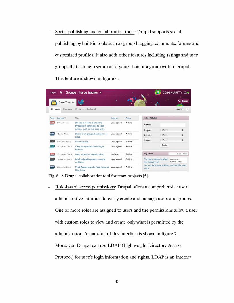
- Social publishing and collaboration tools: Drupal supports social
publishing by built-in tools such as group blogging, comments, forums and
customized profiles. It also adds other features including ratings and user
groups that can help set up an organization or a group within Drupal.
This feature is shown in figure 6.
Fig. 6: A Drupal collaborative tool for team projects [5].
- Role-based access permissions: Drupal offers a comprehensive user
administrative interface to easily create and manage users and groups.
One or more roles are assigned to users and the permissions allow a user
with custom roles to view and create only what is permitted by the
administrator. A snapshot of this interface is shown in figure 7.
Moreover, Drupal can use LDAP (Lightweight Directory Access
Protocol) for user’s login information and rights. LDAP is an Internet

44
protocol that email and other programs use to look up user and group
information from a server.
Fig. 7: User permission interface in Drupal [5].
- Easy connection: With Drupal it is easy to connect a website to other sites
and social networking services across the web. Different and services
allow the Drupal site designers to share data between the Drupal site and
non-Drupal sites. Figure 8 shows this feature.
Fig. 8: Twitter module on Drupal [5].

45
3.2.3 Drupal’s architecture
Building any internal/external website in Drupal is a matter of combining
together various “Building Blocks”. Figure 9 shows Drupal’s layers between other
layers of a website.
Fig. 9: Drupal’s stack between other layers of a website [3].
Almost every aspect of Drupal’s behaviour and functionality is built using a
combination of Core and Add-on Modules. They are files containing PHP
(Hypertext Processor) codes and a set of functionalities that Drupal knows how to
use. Modules add fundamental to complex features to Drupal and generate the
contents of any given page [3], [5].
Generated by CamScanner from intsig.com

46
Users are one of the building blocks in the Core modules that are defined and
assigned roles by the site administrator. As described previously, each role can be
given permissions to do different actions on the website [3].
One of the most important Drupal’s building blocks is Nodes or Contents. Each
node stores a specific kind of content or “content type”. However, they all hold
common properties [3]:
- Author
- Creation date
- Title
- Body content
Nodes can contain specific fields that could be of different types including text,
integer, date-time, computed and so on.
Theming is Drupal’s presentation layer and can rearrange and override CSS
(Cascading Style Sheets), JavaScript, images and HTML (Hypertext Markup
Language). Drupal’s theme system provides special formatting of the site and
controls the layout, colors, fonts, and other specifications of page contents. Page
content is usually presented as XHTML (Extensible Hypertext Markup Language)
through theme system [3], [5].
Core subsystems are the lowest layer of Drupal’s architecture that provide
additional functionalities such as user session handling, security filtering and rely
upon supplement functionality of modules [3].

47
In the bottom layer of figure 9, the backend keeps the Internet connection alive
and includes operating system, web server, database, and PHP. The operating
system handles low-level tasks like network connections, files, and file permissions.
Web server makes the computer accessible over the Internet and uploads the
correct content of any web page. When it comes to content storage, Drupal
framework can be used with several database servers such as MySQL (mysql.com),
Oracle (Oracle, Redwood Shores, CA), and many others [3], [5]. Finally, we get to
the PHP that is a widely used open source general purposed scripting language well
suited for web development [3], [5], [6].
3.3 Software packages
The main software package used in this work is Drupal V.6. All contents and
web pages of the web-based QA management system for RT are created through
Drupal along with PHP programming to customize our needs. We use MySQL as
our database server to store Drupal’s data. All the information such as patient data,
images, contouring, clinical people’s tasks, etc. is retrieved from the clinical ARIA
database which uses Sybase (SAP, sap.com). To access the ARIA database and fetch
required information for our tests we use SQL (Structured Query Language)
(Oracle, Redwood Shore, CA) scripts.
Each QC test form is made out of a “Drupal form”. A form consists of a
collection of fields (pop menus, checkboxes, textboxes, radio buttons, etc.),
organized in a logical manner to follow the flow of the specific QC test. Those forms

48
are defined and created using the concept of nodes explained previously. These
forms may contain different content and come as different formats. They can be a
simple checklist, more complicated forms which involve text and measurement
result entry, forms with simple or complex calculations, and finally forms that
contain an image or other file formats. Some data are entered in the configuration
of the Drupal site such as: the definition of the various measurements tools
(ionization chambers, electrometers, linacs, imaging devices, etc.) using the
taxonomy of Drupal (similar to a dictionary). These data are used as the reference
data for QC tests. Our configuration of Drupal includes:
Scheduling a QC test or a specific task that must be performed by a specific
person or group responsible for that task and sending them email alerts.
These email alerts could work as reminders or warning about tasks that have
not been executed or have been delayed. Also, emails in form of reports
(summary/trends/results/alerts/etc.) can be generated and circulated among
people responsible for a given task.
Generating a PDF version of the forms created for each test
Graphics module to show plots and graphical presentation (trends) of the
QC data
Spreadsheet module that simulate Excel files for some data storage purposes
Possibility of uploading different file formats such as image files and present
them in QC forms
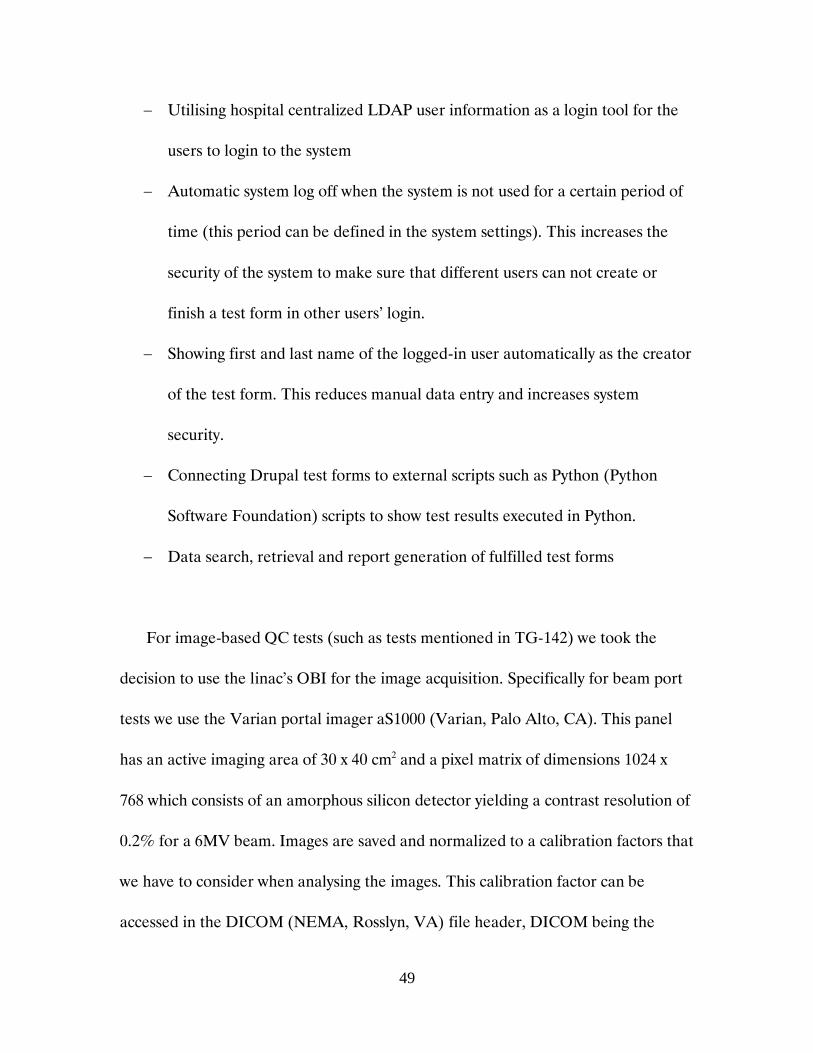
49
Utilising hospital centralized LDAP user information as a login tool for the
users to login to the system
Automatic system log off when the system is not used for a certain period of
time (this period can be defined in the system settings). This increases the
security of the system to make sure that different users can not create or
finish a test form in other users’ login.
Showing first and last name of the logged-in user automatically as the creator
of the test form. This reduces manual data entry and increases system
security.
Connecting Drupal test forms to external scripts such as Python (Python
Software Foundation) scripts to show test results executed in Python.
Data search, retrieval and report generation of fulfilled test forms
For image-based QC tests (such as tests mentioned in TG-142) we took the
decision to use the linac’s OBI for the image acquisition. Specifically for beam port
tests we use the Varian portal imager aS1000 (Varian, Palo Alto, CA). This panel
has an active imaging area of 30 x 40 cm2 and a pixel matrix of dimensions 1024 x
768 which consists of an amorphous silicon detector yielding a contrast resolution of
0.2% for a 6MV beam. Images are saved and normalized to a calibration factors that
we have to consider when analysing the images. This calibration factor can be
accessed in the DICOM (NEMA, Rosslyn, VA) file header, DICOM being the

50
default format in which the images are saved (Digital Imaging and Communication
in Medicine). First, a SQL query is executed through a python scripts initiated by
the Drupal form. This script queries the Unique Identifier number (UID) for the
specific patient/test phantom images from the ARIA database. This UID is then
used in another python script to retrieve (through a DICOM query) the specific
desired image from the ARIA image DICOM server using the pynetdicom
(pynetdicome V. 0.8.0, MIT license, https://pypi.python.org) python modules. This
image is then analyzed by a third python script using Matplotlib, a powerful imaging
module in python [7]. The results of this analysis, (values or graphs/images) can be
injected into the corresponding Drupal form of that test. Figure 10 depicts a
schematic of this flow.
Fig. 10: Flowchart to perform image-based QC tests.
ARIA Image
server
ARIA
Save results
(Qualitative/Image) in
a test form on the
system (Drupal)
DICOM query
specific image
Process
Schedulable script
(Python / Matplotlib,
Pynetdicom, etc.)
SQL query image dataset
to retrieve the UID

51
References
[1] Vasont Systems. Crash course for Content Management
http://www.vasont.com/resources/crash-course/
[2] Enterprise Content Management. What is Content Management?
http://www.contentmanager.eu.com/index.htm
[3] Angela Byron, Addison Berry, Nathan Haug, Jeff Eaton, James Walker, and Jeff
Robbins. Using Drupal. O’REILLY, first edition, 2008.
[4] SearchSOA. Content Management System (CMS)
http://searchsoa.techtarget.com/definition/content-management-system
[5] Drupal website. About Drupal: http://drupal.org/about
[6] http://php.net/manual/en/intro-whatis.php
[7] J. D. Hunter, Matplotlib : A 2D graphics environment, Journal of Computing In
Science and Engineering, Vol. 9, N. 3, P. 90-95, 2007.

52
CHAPTER 4
Results and Discussion
Contents
4.1 Introduction ........................................................................................................... 52
4.2 Implemented QC tests ........................................................................................... 54
4.1 Introduction
Following the discussions in the precedent chapters, a software QA tool has
been developed using Drupal with customized PHP scripts as well as a collection of
python scripts and modules. A large number of QC tests are performed (daily,
monthly, yearly, etc.) in the division of radiation oncology at the Jewish General
Hospital. In the interest of time and to keep the scope of this project reasonable, we
have chosen a handful of these tests (9) to be implemented within our Drupal QA
system. The selection has taken into consideration the relevance of these tests and
their role as a model for further development. For example, we have chosen two
image-based tests to demonstrate the feasibility of all the tests that would use
images acquired by the portal imager to characterize the MLC and the Jaws.
The system is hosted on a virtual linux server running Ubuntu (Ubuntu V.10,
Canonical Ltd, ubuntu.com) in the IT department of the hospital, and is properly
backed up as other clinical application/data hospital wide. It is accessible through a

53
main login webpage using any browser capable device (desktop, tablet and smart
phones) on the hospital intranet. Every hospital user has a centralized user account
at the IT department within the hospital LDAP server. The user rights or
permissions are managed within the Drupal systems through the roles settings of
Drupal. The role of a user is either: administrator, dosimetrist, physicist, engineer,
or technologist. This role defines the user access to the different test modules of the
system. After the user has logged into the system, a series of tests based on user role
are available for him/her to choose. Therefore, not all tests are accessible to all
roles. Users can choose the QC tests they want to perform. The user will first initiate
the test by clicking on it then he/she will fill in the required information. Once
complete the user saves the form, follows the steps required to validate the data
entry, and then finalizes the form, i.e. sealing the results which corresponds to an
electronic signature. Figure 11 shows a snapshot of the login page and figure 12 is
the QC tests selection available to a physicist user after logging into the system.
Fig. 11: User login page with username and password text boxes.

54
Fig. 12: System page after a physicist logs in. It shows the available tests for this role on the
right bar (QA actions) and user account information on the upper left bar (Username). A
linac status menu is also available at the lower left bar to view linacs’ latest status. The status
indicates if the linac is in operational clinical mode.
4.2 Implemented QC tests
Table 2 in next two pages lists the implemented QC tests and their
corresponding properties.
Patient ID - Patient name - Plan information
Patient ID - Patient name – Plan information
Patient ID - Patient name – Plan information
Patient ID - Patient name – Plan information
Patient ID - Patient name – Plan information
Patient ID - Patient name – Plan information
Patient ID - Patient name – Plan information
Patient ID - Patient name – Plan information
Patient ID - Patient name – Plan information
Patient ID - Patient name – Plan information
Username

55
Table 2: Implemented QC tests with their corresponding properties.
Tests Frequency Group Class Form type
On
Dem
and
Da
ily
Wee
kly
Mo
nth
ly
Qu
arte
rly
Bia
nn
ual
ly
An
nu
ally
Ph
ysic
ist
Do
sim
etri
st
Tec
hn
olo
gist
En
gin
eer
Pat
ien
t
Mac
hin
e
Ch
eck
list
Cal
cula
tio
n
Imag
e
Tex
t
(1) Plan QA Dosi /
Physics ✓
✓ ✓
✓
✓
(2) Maintenance
Worksheet ✓
✓
✓ ✓
✓ ✓ ✓
✓
(3) HDR source
change ✓
✓
✓
✓ ✓
(4) Photon /
Electron
Output for
linacs
✓
✓
✓
✓
(5) DLG
measurement ✓
✓
✓
✓
Tests Frequency Group Class Form type

56
Table 2 Continued: Implemented QC tests with their corresponding properties.
Tests Frequency Group Class Form type
On
Dem
and
Da
ily
Wee
kly
Mo
nth
ly
Qu
arte
rly
Bia
nn
ual
ly
An
nu
ally
Ph
ysic
ist
Do
sim
etri
st
Tec
hn
olo
gist
En
gin
eer
Pat
ien
t
Mac
hin
e
Ch
eck
list
Cal
cula
tio
n
Imag
e
Tex
t
(6) Ortho Weekly
QA ✓
✓
✓
✓
(7) Morning QA
for all machines ✓
✓
✓ ✓
(8) Image-based
test: MLC
acceleration
✓
✓
✓ ✓ ✓ ✓ ✓
(9) Image-based
test:
Asymmetric
collimator jaws
✓
✓
✓ ✓ ✓ ✓ ✓

57
As shown in Table 2, we have classified the tests by their frequency, user groups,
class (machine/patient), and Drupal form types.
The following pages describe the results of the implemented tests. It should be
noted that the data content in the reports presented in this section are tests data and
do not necessarily represent real measured clinical data. Each of them was
extensively tested but not all of them are in clinical use at the time this thesis is
being written.
(1) Plan QA Dosi / Physics: This test is meant to be a written electronic recorded
verification of the key items that the different groups (dosimetrists and
physicists) verify before releasing a treatment plan to the treatment unit. It
basically consists of an extensive check list of treatment plan dosimetric and
physical properties. It is naturally based on a checklist form and is generated
every time a new treatment plan is being approved within the Eclipse treatment
planning system. Treatment course and plan information are retrieved by
querying ARIA by filtering only the patient names/IDs that have an approved
plan at the time of the query therefore saving searching time for the specific
patients and minimizing data entry error as all the required demographic and
plan information for this patient will be transferred directly from Aria. This
checklist runs in two steps. First the dosimetrist initiates the dosimetry checklist
by filtering for the proper patient and completes the dosimetry checklist. Next, a
physics checklist tests follows that dosimetry check and is generated and

58
completed by physicist. Figure 13 shows the PDF report generated by our
system for the Physics part of that checklist. Note that we find all demographic
information as well as planning details and the list of checked items.
Figure 13: Plan QA Physics verification report. It contains patient demographics and
plan specific information as well as checked items.
(2) Maintenance worksheet: This form is meant to replace our current machine
maintenance intervention paperwork. The paper form is not optimal since it
requires many levels of signatures and follow-ups hence very likely to cause
unwanted delays and communication problems. The Drupal implementation of
that form can be used sequentially by (1) the technologist who reports the
problem; (2) the engineer who fixes the problem and finally (3) by the physicist

59
who performs relevant QC tests required to release the specific machine
clinically. Once the problem is reported by the technologist, a form is initiated
on which the problem is described and the form is saved. The engineering team
receives an email with a link to the reported problem page in the system. After
fixing the equipment, the engineering team fill-in and save its section of the
form describing the details of corrective actions. At this moment an email is sent
to the physicist of the day who is responsible to continue the process. The
physicist of the day is determined by a simple SQL query to the Aria database
that looks at the schedule and returns the physicist of the day. The form is then
ready for this physicist to complete when the relevant machine verifications are
performed and machine is ready for clinical use. Figure 14 shows the report
summary of the problem and actions taken.
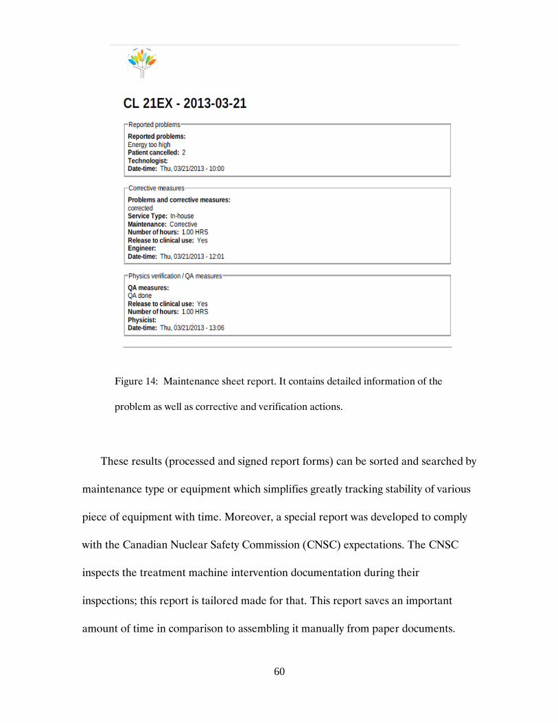
60
Figure 14: Maintenance sheet report. It contains detailed information of the
problem as well as corrective and verification actions.
These results (processed and signed report forms) can be sorted and searched by
maintenance type or equipment which simplifies greatly tracking stability of various
piece of equipment with time. Moreover, a special report was developed to comply
with the Canadian Nuclear Safety Commission (CNSC) expectations. The CNSC
inspects the treatment machine intervention documentation during their
inspections; this report is tailored made for that. This report saves an important
amount of time in comparison to assembling it manually from paper documents.

61
(3) HDR source change: This test replaces an excel sheet and is to be filled out
during our HDR source change. The physicist who supervises the source change
enters the new source data (serial number, apparent activity, etc.) from the
“Certificate for Sealed Sources” provided by the manufacturer and performs all
mandatory measurements: new source strength / activity and position
verification measurements and logs all the information into the system. Using
the Drupal form minimizes manual intervention and data manipulation. The
Drupal form is generated every time our HDR source needs to be replaced. A
sample image of the sealed source certificate is uploaded in the system to guide
the users through the proper sequence of data entry. Calculation information
for different values such as measured and expected activity, as well as relevant
electrometer and chamber information are available through a hyperlink
accessible at the top of the HDR source change form. Pressure, temperature
and dosimetric readings for several dwell positions are performed and recorded
in the Drupal form. Measured source activity is calculated (from source strength
values) and compared to the expected activity (calculated from source data
entered from source data sheet). By the time the physicist is satisfied with the
results, he/she moves to the next step of the form that consists of completing
activity updates (updated automatically from previously calculated values) and
completes the process. A summary report of all the measurements and
calculations is generated at the end of the process that is shown in figure 15.

62
Figure 15: HDR source change report. Details of source information, measurements
and activity updates are comprised in this report.
(4) Photon / Electron Output for linacs: This form replaces an Excel sheet that is
used to enter QC test data for photon or electron beam output tests. This test is

63
recommended by TG-142 to verify the photon and electron beam output
consistency and is performed by physicists on a monthly basis at the JGH. A
verification of the outputs is also performed by technologists every morning
during the warm-up of the linacs with a BeamChecker (QA Beamchecker Plus,
Standard Imaging, Middleton, WI). The BeamChecker data is not yet integrated
in our system. For our Drupal output test, the ion chamber readings are
measured, corrected for temperature and pressure and recorded for each beam
energy for both electron and photon beams. The output is then calculated from
TG-51 data which is available within our Drupal system: Percent Depth Dose
(PDD) for photon beams and Transfer Coefficient (TC) for electron beams.
Finally these numbers are compared to the yearly calibration data to ensure that
the test passes and linac output are consistent for both electron and photon
beams. In Drupal, this form is initiated by selection of the linac type and
preconfigured ion chambers and electrometers corresponding to the selected
linac. Also, setup information is available on the initial page of the form to
ensure that physicists follow correct setup while performing the test. In the next
step, all the calibration data retrieved from TG-51 QC results performed
annually are imported for each linac depending on the beam type (photon or
electron) and energy selected. Calibration data is available in a form that was
created to keep the annual calibration data that will be used in other QC tests.
These data include factors such as PDD (photon beams) and TC (electron

64
beams). After ion chamber readings are performed and output calculations are
executed in the Drupal form, the physicist reviews all these data and decides to
either finalize the measurements or repeat them depending on how satisfactory
the results are. Figures 16 and 17 show the results for both photon and electron
output tests generated by the system.
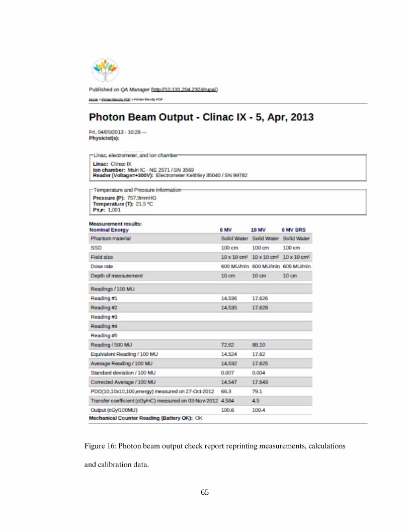
65
Figure 16: Photon beam output check report reprinting measurements, calculations
and calibration data.

66
Figure 17: Electron beam output check report representing measurements,
calculations and calibration data.

67
A trend of the output for both photon and electron beams is available for all
linacs and can be accessed through a search tool by filtering the linac type, its
corresponding ion chamber and test date. A screen shot of this trend for 6 MV
photon beams of the Varian linac IX, measured by Main IC is shown in figure 18.
Figure 18: Beam output trend filtered for linac type, ion chamber and date.
(5) DLG Measurement: The Dosimetric Leaf Gap (DLG) measurement is one of
linac monthly tests to verify the stability of the MLC leaf gap that is a critical
factor in the delivery of intensity modulated radiotherapy beams i.e. IMRT or
VMAT plans. The Drupal form for this test replaces an Excel sheet to log and
Ou
tpu
t [c
Gy/1
00M
U]
Date
12.12.24 13.04.05 13.04.05 13.04.05

68
calculate the test results. Ion chamber readings for several nominal leaf gap
values ranging from 2 mm to 20 mm are entered in the form and the leaf gap
value for which there is no transmission (null reading) is calculated. This value
is calculated by extrapolation of the measurements data. The Drupal form is
initiated by choosing linac type and corresponding ion chamber and
electrometer. In the next step, ion chamber readings for all nominal gaps are
measured, entered and saved in the form. However, no leaf gap value is
calculated and presented until the last measurement i.e. the measurement of 20
mm gap is executed. This is to avoid any misleading that could happen during
analysis if this value was calculated and shown after each nominal gap
measurement. Finally, the physicist saves and finalizes the test when he/she is
satisfied with the test results. Figure 19 is an example of the DLG measurement
test report generated by our system.

69
Figure 19: DLG Measurement test report.
(6) Orthovoltage Weekly QA: This test consists of an output (dose to water
Dw (in cGy) / 100 MU at the reference point) check for all beam qualities of the
orthovoltage machine. This test is performed on weekly basis. The Drupal form
replaces the Excel sheet used for this test. In the Drupal form for this test, the
ion chamber readings for each beam quality are entered one by one. Readings
are then corrected taking into consideration the ion chamber polarity ( Ppol), the
ion recombination (Pion), the temperature and pressure (Pt,p), etc. These
correction factors are retrieved from the annual measurements data that are

70
saved in a separate Drupal form. Physicists see values of these correction factors
in a table format on the Drupal form of this test. In the next step, dose to water
the output is calculated using the annual TG-61 calibration coefficients (Nk) for
each energy. These calculated outputs are compared to the annual
measurements and a percentage difference value is calculated. These
differences must lie within the accepted range of action level (3%). Finally,
physicist can terminate the test and view the report table that consists of the
readings, correction factors and calculations. At this time, a summary of the
performed QC test including outputs and difference values is generated and
sent automatically to the physicist who supervises the QC of the orthovoltage
machine for a quick review of the test result. For the purpose of ensuring that
the test is performed on weekly basis, a schedule that checks the creation of this
QC test report runs every Friday evening. If the QC test is not performed, the
physicist who supervises the QC of this unit receives an email alert/warning.
Furthermore, a trend of the dose to water can be generated by filtering test date
and beam quality. In figure 20 and 21 a sample of the test report and dose to
water trend for all beam qualities are shown consecutively.

71
Figure 20: Orthovoltage weekly QA report presenting measurements, calculations
and calibration data.

72
Figure 21: Beam output trend by date for each orthovoltage beam quality.
Ou
tpu
t [c
Gy/M
U]
Ou
tpu
t [c
Gy/M
U]
Ou
tpu
t [c
Gy/M
U]
Ou
tpu
t [c
Gy/M
U]
Week of the year

73
(7) Morning QA: This test consists of an exhaustive checklist that is filled out every
morning by the technologist who performs the warm-up of specific equipment
and ensures that all important aspects of that equipment are as working
properly. Drupal checklists are created for linacs, Acuity Simulator (Varian,
Palo Alto, CA), Brachytherapy HDR afterloader unit (Microselectron V3,
Elekta, Stockholm, Sweden), LightSpeed RT 16 CT-Simulator (GE Healthcare,
Little Chalfont, United Kingdom) and orthovoltage unit (XStrahl Ltd.,
Camberley, United Kingdom). All procedures and safety instructions for each
machine can be accessed through the links available on their corresponding
Drupal test forms. Another feature of this module is the email alerts that are
sent to the chief technologist in case of an incomplete or non-performed
morning QC test of any equipment at a specific time of the day. This time is
configurable in the system. However, this email is not generated during
weekends.
In the following section, we discuss the results of the two image-based QC tests
that we have implemented in our system (MLC acceleration and asymmetric jaws
tests).
(8) MLC acceleration test: This is a quarterly QC test that verifies that the
acceleration of a linac’s MLC leafs is consistent in time. For each linac, a pre-
defined QA treatment plan that consists of a complex MLC sequence is

74
delivered and an image is recorded on the portal imager. Figure 22 is a sample
of the recorded image on the portal imager.
Figure 22: MLC acceleration test image acquired on the portal imager of a linac.
To analyse the performance of the MLC, the acquired image in figure 22 is
retrieved through the process described in section 3.2.4. The image is then
analysed by calculating and comparing dose delivered to two different regions of
the image. These Regions of Interests (ROI) are defined and the mean pixel

75
values as well as standard deviations of the pixel values are calculated. Finally,
the difference between mean pixel values of the two ROI’s are calculated. A test
with difference value less than or equal to 3% is considered as passed. An
example of the results of the test is shown in figure 23.
Figure 23: MLC acceleration test results by python script. The acquired image on the
imager with defined ROI’s (top figure). ROI analysis results (bottom figure).
The same MLC pattern test is performed using Gafchromic film (EBT2,
Ashland, Wayne, NJ) but as described, our system allows automatic analysis of the
pattern by recording it on the portal imager.

76
(9) Collimator Asymmetric Jaws test: This is a quarterly QC test to verify the linac
asymmetric junction of the jaws. Four asymmetric fields of 5 x 5 cm2 are
delivered sequentially, each being a quadrant of a 10 x 10 cm2 area. The
composite irradiation of these four fields would ideally yield a flat 10 x 10 cm2
field. In reality we observe a cross at their junction that we want to characterize.
We want to perform our test with the portal imager of the linac to simplify the
analysis of the results as we directly obtain a digital image in the form of a
DICOM file in the clinical database. We validated our technique with our
current clinical practice, i.e. using Gafchromic film (EBT2, Ashland, Wayne,
NJ) where the four irradiations are recorded on one piece of film. The
irradiated film is scanned and analysed using the Film QA Pro (Film QA Pro
2013, Ashland, Wayne, NJ) software with an Epson scanner (10000XL, Suwa,
Nagona, Japan). From Film QA Pro we obtain a calibrated image that is
proportional to dose using the clinical calibration curves of the EBT2 film. For
the portal imager acquisition, we repeat three times the irradiation of four
quadrants to get better statistics on the image by taking a simple average of
them. As the portal imager doesn’t move between the irradiation of the four
quadrants, the images are inherently aligned and the average of the four images
could potentially also average errors from small motion of the whole carriage.
Figure 24 shows the four quadrant images acquired on the portal imager.

77
Figure 24: Four asymmetric fields of 5 x 5 cm2.
Dark regions on the fields are artefacts caused by the display settings
limitations (image width and level). The image data is good.
The 12 DICOM images are retrieved by the process described in section 3.2.4
to be used as the inputs of a python script that analyses the junctions. Images are
first averaged and merged to reconstruct the final image (similar to the image
acquired on the film). As explained above radiographic film was also irradiated
simultaneously to compare the results with the results of the portal images.

78
Figures 25 and 26 show the reconstructed image from the 12 portal images and
the image acquired with a film.
Figure 25: Reconstructed image of the image acquired on the portal imager.
Figure 26: Image acquired on the film (scaling is different on both images).

79
We investigated and compared two different features of these two images:
1) Measurement of the irradiated flat fields on each image shows that both of
these fields represent a 10 x 10 cm2
2) In both images, as expected, we observe a cross at the jaw junctions
resulting from four asymmetric field irradiations.
To characterize the junctions, we first look at the dose profiles (on the film or on
the portal images) at the jaw junctions i.e. X1, X2, Y1, Y2. Figures 27 and 28
show these dose profiles for one pixel line in Calibrated Units (CU) (for the
portal images) and in dose percentage (for the film). Both set of curves are
proportional to dose and can be normalized for means of inter-comparison.
Figure 27: Jaw junctions’ dose profiles in CU from the portal images analysis;
Y2 (upper left); Y1 (lower left); X2 (upper right); X2 (lower right).

80
Figure 28: Jaw junctions’ dose profile in dose percentage from the film analysis;
Y2 (upper left); Y1 (lower left); X2 (upper right); X2 (lower right).
The profiles of the portal images are smoother than the film profiles. This
results from the characteristics of the aS1000 portal imager that reduces noise to
improve image quality. For the full analysis and comparison we are interested in
obtaining a numerical quantification of the junctions. To get better statistics and
Y2 jaw
Y1 jaw X1 jaw
X2 jaw

81
a more reliable analysis we have decided to use an average of many profiles over
an ROI across the junction as shown in figure 29. Two parameters are reported:
1. Dose difference between minimum / maximum dose value at jaw junctions
in the dose profile and the adjunct dose values. We would like to make sure
that this value is not exceeding 5%.
2. Full width at half maximum (FWHM) for the four junctions.
For this analysis, we decided to choose four regions of interest (ROI) that
include jaw junctions on the reconstructed image as shown in figure 29.
Figure 29: ROI’s at four jaw junctions on the portal image.
82
Each green ROI is “collapsed” on the vertical direction to obtain one
average dose profile and each blue ROI is “collapsed” or averaged on the
horizontal direction. These averaged one dimensional arrays of pixels are shown
in figure 30.
Figure 30: Dose profiles in CU for the ROI’s at the four jaw junctions; ROI1, Y2(upper
left); ROI2, Y2(lower left); ROI1, X1(upper right); ROI2, X1(lower right).

83
The results of our analysis script are shown in figure 31.
Figure 31: Dose profile analysis. Min/max dose difference and FWHM.
Finally, the same analysis was performed on the film and the comparison
between the two methods is presented in tables 3 and 4. Values in the tables are
calibrated and scaled values.
Jaw
Min/Max dose difference
Portal image Film
(%) (%)
Y1 3.8±0.7 3.6±1.5
Y2 5.0±1.0 4.8±1.9
X1 4.7±0.9 4.9±1.6
X2 4.8±0.9 4.9±1.6
Table 3: Comparison of min/max dose difference between the film image and the
portal image.

84
Jaw
FWHM
Portal image Film
(± 0.8 mm) (± 0.2 mm)
Y1 3.5 3.5
Y2 4.7 4.6
X1 3.9 3.8
X2 3.8 3.8
Table 4: Comparison of FWHM analysis between the film and the portal image. The
third column represents the percentage difference between the value obtained with
the portal imager and the film.
In table 3, the uncertainties for the max/min dose differences are calculated
based on the standard deviation of a flat area of the image (0.2 in CU for the
portal image and for the 0.4 in dose percentage for the film). We can see that the
max/min difference values for the portal and the film images are equal within
their respective errors.
In table 4, the uncertainty for the FWHM values is ± 0.78 mm (equal to the
portal imager pixel pitch (distance between two pixels)) for the portal images
and ± 0.17 mm for the film. We can see that the FWHM values for the portal
and the film images are equal within their respective errors.

85
CHAPTER 5
Conclusions and Future Work
5.1 Conclusions ............................................................................................................ 85
5.2 Future Work .......................................................................................................... 86
5.1 Conclusions
We have successfully implemented a web-based quality control system for the
division of radiation oncology at the Jewish General Hospital. Our system is based
on the popular open source Content Management System Drupal. We have
extended the capabilities of Drupal by using some custom PHP and Python scripts as
well as some specialized Drupal modules. The various quality control tests are
implemented as Drupal forms containing several fields to select or fill up. The
system manages user login through the hospital’s LDAP server. Group rights are
defined through specific modules in the Drupal system. Our system can directly
query our Electronic Medical Record database for patient and plan information as
well as our image database through DICOM queries for image-based tests.
This tool favourably replaces many Excel sheets and paper forms as it provides
an easy access to users and managers. It optimizes QA data entry and minimizes the
possibility of errors and provides easier storage and retrieval of these data within
our radiation oncology division. Based on a centralized database, it is accessible to

86
users on desktop computers, smart phones, tablets, etc. and considerably facilitates
trend keeping and report generation (PDF/ graphical trends/summary/etc).
Functions such as scheduling and email alerts, allow more efficient management and
supervision of the workflows within our department. Moreover, data transfer from
the EMR and TPS of our department offers a fast and reliable way to enter
important data to the system. Using hospital LDAP as a login tool and the
possibility of electronic signature of the logged-in user saves time for paper
signature and improves security of the system.
Image-based QC tests (MLC acceleration and Asymmetric Jaws tests) executed
on the portal imager replace the film acquisition and manipulation hence greatly
simplifying the workflow for these tests. This approach also allows “automatic”
analysis from daily or weekly image acquisition performed by technologists as part
of a morning QA for example.
5.2 Future Work
Extending our tool to support all other QC tests that are performed as part of
our QA program is a priority. We have established a broad range of capabilities with
the already implemented tests and their specifications should be sufficient to cover
all other tests.
Additional work on scheduling tests, e-calendars, email alerts/reports and
automatic updating of the equipment’s clinical status would be greatly profitable,
principally in making these options more organized globally within the tool.

87
Image-based tests performed on the portal imager are numerous and advanced
image analysis tools are available to us through specialised python modules. The
possibility of automatic analysis of any image acquisition is certainly to be explored
as they could be incorporated in the morning QC tests performed routinely by
technologists. Results of these tests could be trended and reported automatically.
Future extension could include direct communication with some measurement
tool such as electrometers and specialized devices (Beamchecker, Profiler II (Sun
Nuclear Corp., Melbourne, FL), Matrix (IBA, Louvain-la-Neuve, Belgium), etc.).
The recent install of a TrueBeam linac (Varian, Palo Alto, CA) in our clinic opens
the door to complex, extensive and automatic tests as this new linac can fully be
controlled with external scripts (codes in XML (W3C Document License, w3.org)).
One can imagine coding an automatic sequence of QC tests to perform on this linac,
fully controlling all parameters of the delivery and saving their results directly in our
QA tool.

88
REFERENCES
[1] Todd Pawlicki, and Aron J. Mundt. Quality in radiation oncology. Med. Phys. 34
(5), 2007.
[2] Druker, Peter. Innovation and entrepreneurship practices and principals. Harper
& Raw, 1985.
[3] Crosby, Phillip. Quality is free. McGraw-Hill, New York, 1979.
[4] American Society of Quality: http://asq.org
[5] Faiz, M. Khan. The physics of Radiotherapy. Lippincott Williams & Wilkins,
third edition, 2003.
[6] American Association of Physicists in Medicine. AAPM TG-53 Report: Quality
Assurance for clinical radiotherapy treatment planning, 1998.
[7] Canadian Cancer Society. Cancer Canada: Cancer treatment
http://www.cancer.ca/Quebec/About%20cancer/Treatment/Radiation/External%
20beam%20radiation%20therapy.aspx?sc_lang=en&r=1
[8] American Association of Physicists in Medicine. AAPM TG-46 Report:
Comprehensive QA for radiation oncology, 1994.

89
[9] International Commission on Radiation Units and Measurements. ICRU report
62: Prescribing, recording and reporting photon beam therapy (Supplement to
ICRU report 50)
[10] Peter Dixon, Brian O’sallivan. Radiotherapy Quality Assurance: Time for
everyone to take it seriously. European Journal of cancer. 39 (4), 2003.
[11] European Society for Therapeutic Radiology and Oncology. ESTRO:
Recommendations for a Quality Assurance programme in External
Radiotherapy, First edition, 1995.
[12] Thwaits DI., Mijnhaer BJ., and Mills JA. Quality Assurance of External Beam
Radiotherapy in radiation oncology physics: A handbook for teachers and
students, E.B. Podgorsak (editor), IAEA, Vienna, Austria, 2005.
[13] Canadian Association of Provincial Cancer Agencies. CAPCA, Standards for
Quality Control at Canadian Radiation Treatment Centres: Major dosimetry
equipment, 2007.
[14] American Association of Physicists in Medicine. AAPM TG-13 Report:
Physical aspects of Quality Assurance in Radiation Therapy, 1994.
[15] L.W. Brady, H.P. Heilmann, M. Molls, and C. Nieder. Technical basis of
Radiation Therpay: Practical clinical applications, Seymour H. Levitt et al.
(editors), fifth edition, 2012.

90
[16] Canadian Partnership for Quality Radiotherapy. CPQR, Technical Quality
Control guidelines for Canadian Radiation Treatment centres: Major dosimetry
equipment, 2012.
[17] Canadian Association of Provincial Cancer Agencies. CAPCA, Standards for
Quality Control at Canadian Radiation Treatment Centres: Co-60 Teletherapy
unit, 2006.
[18] E.B. Podgorsak, Treatment machines for External Beam Radiotherapy: A
handbook for teachers and students, E.B. Podgorsak (editor), IAEA, Vienna,
Austria, 2005.
[19] American Association of Physicists in Medicine. AAPM TG-142 Report:
Quality Assurance of medical accelerator, 2009.
[20] Canadian Partnership for Quality Radiotherapy. CPQR, Technical Quality
Control guidelines for Canadian Radiation Treatment centres: Medical Linear
Accelerators and Multileaf Collimators, 2012.
[21] American Association of Physicists in Medicine. AAPM TG-50 Report: Basic
applications of Multileaf Collimators, 2001.
[22] James M. Galvinn, The Multileaf Collimator-A complete guide, 1999.

91
[23] Canadian Partnership for Quality Radiotherapy. CPQR, Technical Quality
Control guidelines for Canadian Radiation Treatment centres: Kilovoltage
X-ray radiotherapy machines, 2012.
[24] Canadian Association of Provincial Cancer Agencies. CAPCA, Standards for
Quality Control at Canadian Radiation Treatment Centres: Stereotactic
Radiosurgery/Radiation Therapy, 2006.
[25] American Association of Physicists in Medicine. AAPM Report No. 54:
Stereotactic Radiosurgery, 1995.
[26] American Association of Physicists in Medicine. AAPM TG-135 Report:
Quality Assurance for robotic radiosurgery, 2011.
[27] American Association of Physicists in Medicine. AAPM TG-56 Report: Code
of practice for brachytherapy physics, 1997.
[28] Canadian Partnership for Quality Radiotherapy. CPQR, Technical Quality
Control guidelines for Canadian Radiation Treatment centres: Brachytherapy
remote afterloaders, 2012.
[29] American Association of Physicists in Medicine. AAPM TG-58 Report: Clinical
use of Electronic Portal Imaging, 2001.

92
[30] Canadian Association of Provincial Cancer Agencies. CAPCA, Standards for
Quality Control at Canadian Radiation Treatment Centres: Simulators, 2005.
[31] Canadian Association of Provincial Cancer Agencies. CAPCA, Standards for
Quality Control at Canadian Radiation Treatment Centres: CT Simulators,
2007.
[32] E. Schreibemann, E. Elder, and T. Fox, Automated Quality Assurance for
Image-Guided Radiation Therapy, Journal of Applied Clinical Medical Physics.
10 (1), 2009.
[33] S. Yoo, T. Pawlicki et al., A quality assurance program for the on-board imager,
The International Journal of Medical physics Research and Practice. 33 (11),
2006.
[34] Canadian Association of Provincial Cancer Agencies. CAPCA, Standards for
Quality Control at Canadian Radiation Treatment Centres: EPID, 2005.
[35] N. Aguzaryan, T. Solberg, and J. J. DeMarco, Patient Specific Quality
Assurance for delivery of Intensity Modulated Radiotherapy, Journal of
Applied Clinical Medical Physics. 4 (1), 2003.
[36] Canadian Partnership for Quality Radiotherapy. CPQR, Technical Quality
Control guidelines for Canadian Radiation Treatment centres: Treatment
Planning Systems, 2012.
93
[37] American Association of Physicists in Medicine. Report of the IMRT
subcommittee of the AAPM radiation therapy committee: Guidance document
on delivery, treatment planning and clinical implementation of IMRT, 2003.
[38] J. Izewska, H. Svensson, and G. Ibbott, Worldwide Quality Assurance networks
for radiotherapy dosimetry, 2003.
[39] IAEA, Quality Assurance in Radiation Therapy, Vienna, Austria, 1997.
[40] American Association of Physicists in Medicine. AAPM Report No. 100:
Acceptance Testing and Quality Assurance Procedures for Magnetic Resonance
Imaging Facilities, 2010.
[41] American Association of Physicists in Medicine. AAPM TG-126 Report: PET
and PET/CT Acceptance Testing and Quality, 2009.
[42] J. F. Box, Guiness, Gosset, Fisher, and small samples, Statistical Science. Vol. 2,
No. 1, 1987.
[43] D. Létourneau, A. McNiven, DA. Jaffray. Multicenter collaborative Quality
Assurance program for the province of Ontario: first-year results. International
journal of radiation oncology biology physics. 86(1), 2003.

94
[44] Canada Health Infoway: EMR
https://www.infoway-inforout.ca/index.php/programs-services/certification-
services/what-infoway-certifies/emr
[45] Ministry of Health of British Columbia: e-Health – Faster, safer, better health
care (EMR)
http://www.health.gov.bc.ca/ehealth/emr.html
[46] Varian medical systems. ARIA overview
http://www.varian.com/us/oncology/radiation_oncology/aria/
[47] American Association of Physicists in Medicine. AAPM TG-53 Report: Quality
Assurance for clinical radiotherapy treatment planning, 1998.
[48] Vasont Systems. Crash course for Content Management
http://www.vasont.com/resources/crash-course/
[49] Enterprise Content Management. What is Content Management?
http://www.contentmanager.eu.com/index.htm
[50] Angela Byron, Addison Berry, Nathan Haug, Jeff Eaton, James Walker, and
Jeff Robbins. Using Drupal. O’REILLY, first edition, 2008.
[51] SearchSOA. Content Management System (CMS)
http://searchsoa.techtarget.com/definition/content-management-system

95
[52] Drupal website. About Drupal: http://drupal.org/about
[53] http://php.net/manual/en/intro-whatis.php
[54] J. D. Hunter, Matplotlib : A 2D graphics environment, Journal of Computing In
Science and Engineering, Vol. 9, N. 3, P. 90-95, 2007.