Embed Size (px)
Citation preview

WEAVE Top End General Assembly &
Alignment Overview
Kevin Dee
09 March 2015
WEAVE. Isaac Newton Group of Telescopes 13/9/2015 KMDee
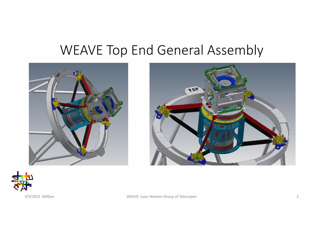
WEAVE Top End General Assembly
WEAVE. Isaac Newton Group of Telescopes 23/9/2015 KMDee
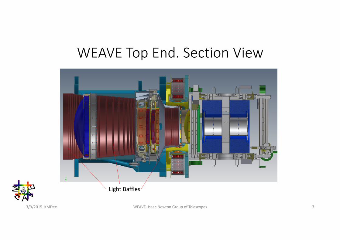
WEAVE Top End. Section View
WEAVE. Isaac Newton Group of Telescopes 33/9/2015 KMDee
Light Baffles
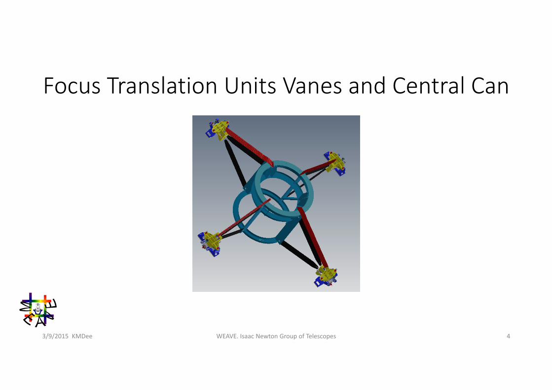
Focus Translation Units Vanes and Central Can
WEAVE. Isaac Newton Group of Telescopes 43/9/2015 KMDee
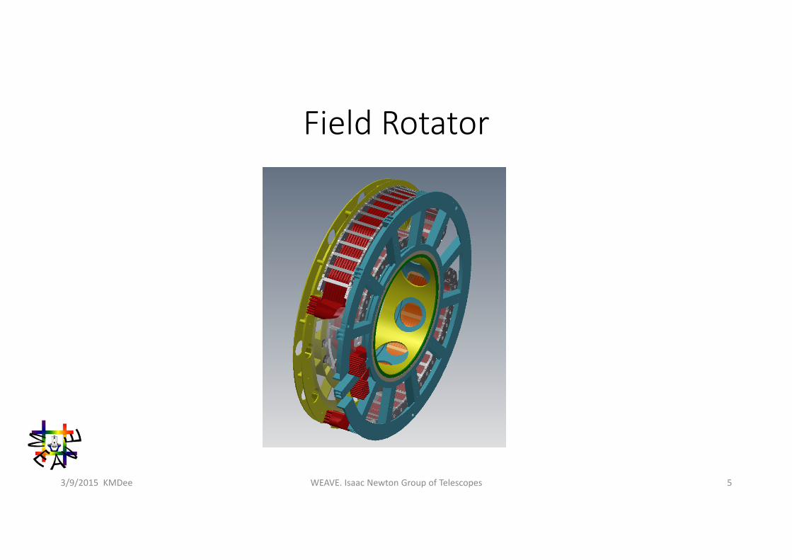
Field Rotator
WEAVE. Isaac Newton Group of Telescopes 53/9/2015 KMDee
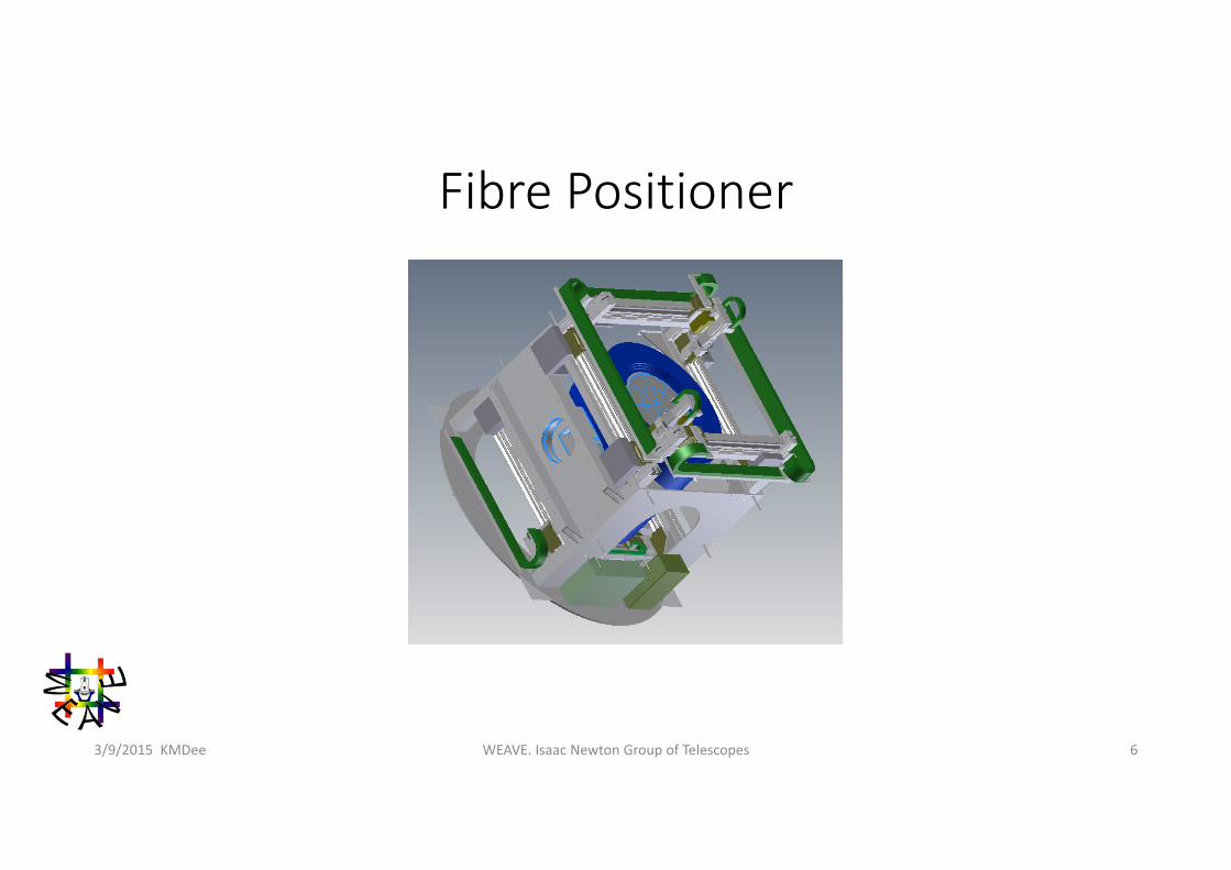
Fibre Positioner
WEAVE. Isaac Newton Group of Telescopes 63/9/2015 KMDee
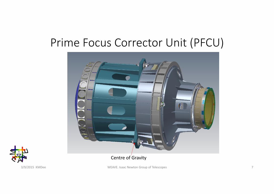
Prime Focus Corrector Unit (PFCU)
WEAVE. Isaac Newton Group of Telescopes 73/9/2015 KMDee
Centre of Gravity
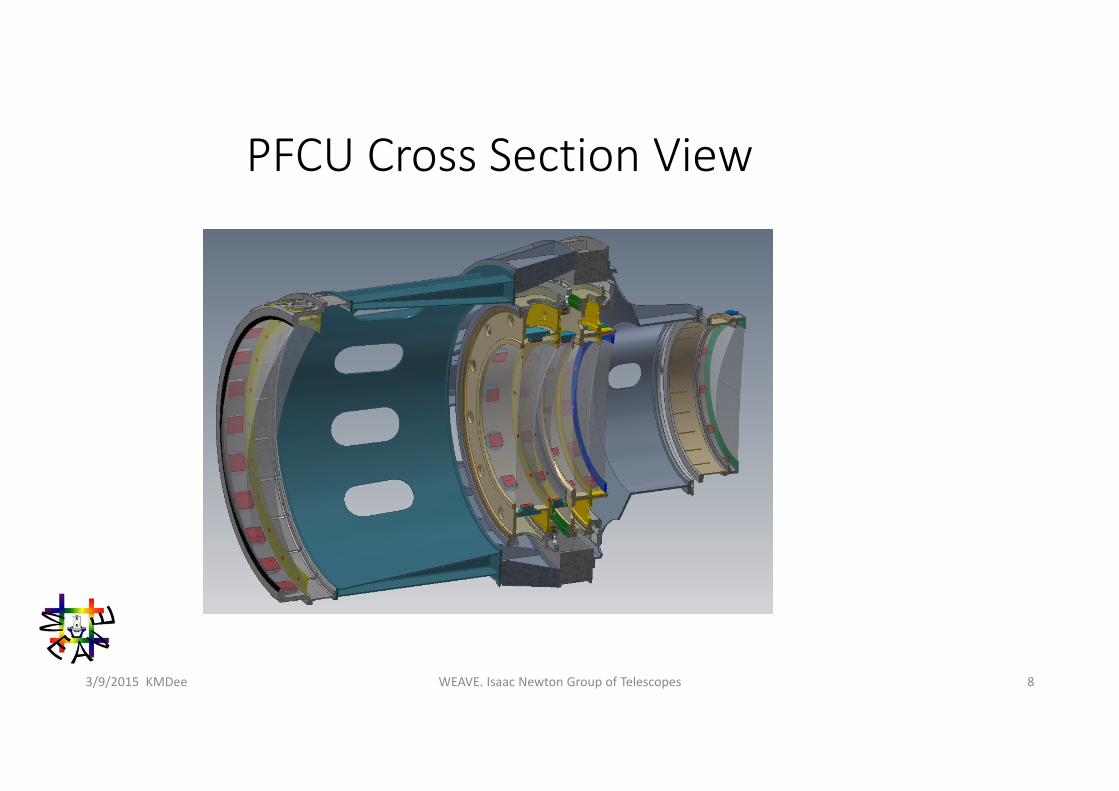
PFCU Cross Section View
WEAVE. Isaac Newton Group of Telescopes 83/9/2015 KMDee
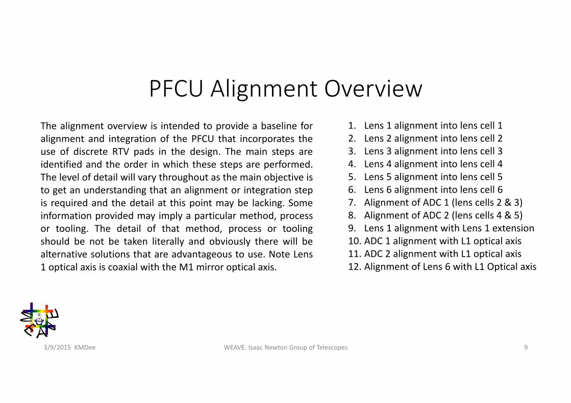
PFCU Alignment Overview
WEAVE. Isaac Newton Group of Telescopes 93/9/2015 KMDee
1. Lens 1 alignment into lens cell 12. Lens 2 alignment into lens cell 23. Lens 3 alignment into lens cell 34. Lens 4 alignment into lens cell 45. Lens 5 alignment into lens cell 56. Lens 6 alignment into lens cell 67. Alignment of ADC 1 (lens cells 2 & 3)8. Alignment of ADC 2 (lens cells 4 & 5)9. Lens 1 alignment with Lens 1 extension10. ADC 1 alignment with L1 optical axis11. ADC 2 alignment with L1 optical axis12. Alignment of Lens 6 with L1 Optical axis
The alignment overview is intended to provide a baseline foralignment and integration of the PFCU that incorporates theuse of discrete RTV pads in the design. The main steps areidentified and the order in which these steps are performed.The level of detail will vary throughout as the main objective isto get an understanding that an alignment or integration stepis required and the detail at this point may be lacking. Someinformation provided may imply a particular method, processor tooling. The detail of that method, process or toolingshould be not be taken literally and obviously there will bealternative solutions that are advantageous to use. Note Lens1 optical axis is coaxial with the M1 mirror optical axis.
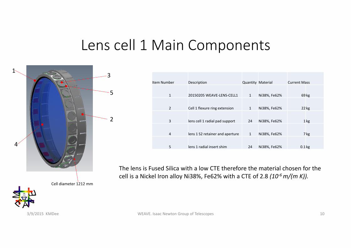
Lens cell 1 Main Components
WEAVE. Isaac Newton Group of Telescopes 103/9/2015 KMDee
Item Number Description Quantity Material Current Mass
1 20150205 WEAVE‐LENS‐CELL1 1 Ni38%, Fe62% 69 kg
2 Cell 1 flexure ring extension 1 Ni38%, Fe62% 22 kg
3 lens cell 1 radial pad support 24 Ni38%, Fe62% 1 kg
4 lens 1 S2 retainer and aperture 1 Ni38%, Fe62% 7 kg
5 lens 1 radial insert shim 24 Ni38%, Fe62% 0.1 kg
The lens is Fused Silica with a low CTE therefore the material chosen for the cell is a Nickel Iron alloy Ni38%, Fe62% with a CTE of 2.8 (10‐6 m/(m K)).
13
5
2
4
Cell diameter 1212 mm
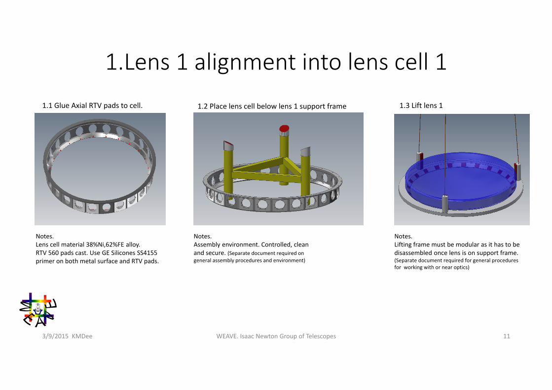
1.Lens 1 alignment into lens cell 1
WEAVE. Isaac Newton Group of Telescopes 113/9/2015 KMDee
Notes. Lens cell material 38%Ni,62%FE alloy.RTV 560 pads cast. Use GE Silicones SS4155 primer on both metal surface and RTV pads.
1.1 Glue Axial RTV pads to cell. 1.2 Place lens cell below lens 1 support frame 1.3 Lift lens 1
Notes. Assembly environment. Controlled, clean and secure. (Separate document required on general assembly procedures and environment)
Notes. Lifting frame must be modular as it has to be disassembled once lens is on support frame. (Separate document required for general procedures for working with or near optics)
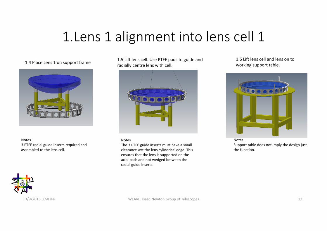
1.Lens 1 alignment into lens cell 1
WEAVE. Isaac Newton Group of Telescopes 123/9/2015 KMDee
Notes. 3 PTFE radial guide inserts required and assembled to the lens cell.
1.4 Place Lens 1 on support frame 1.5 Lift lens cell. Use PTFE pads to guide and radially centre lens with cell.
1.6 Lift lens cell and lens on to working support table.
Notes. The 3 PTFE guide inserts must have a small clearance wrt the lens cylindrical edge. This ensures that the lens is supported on the axial pads and not wedged between the radial guide inserts.
Notes. Support table does not imply the design just the function.
1.Lens 1 alignment into lens cell 1
WEAVE. Isaac Newton Group of Telescopes 133/9/2015 KMDee
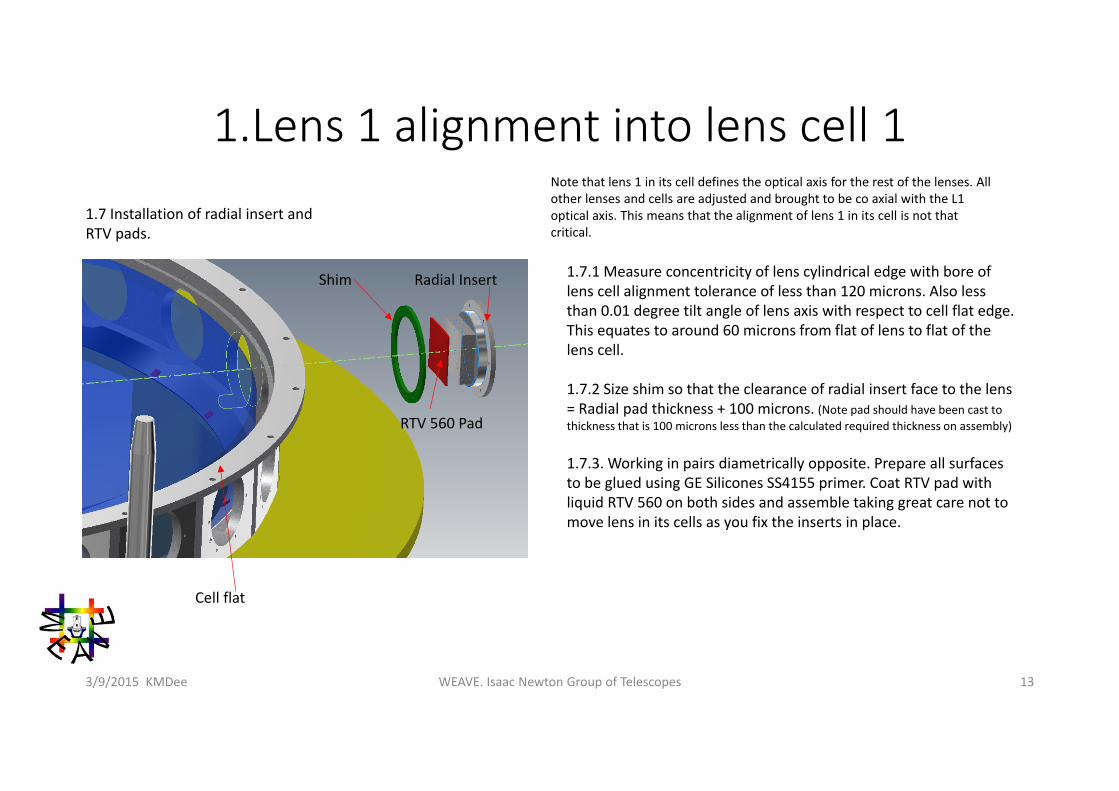
1.7 Installation of radial insert and RTV pads.
1.7.1 Measure concentricity of lens cylindrical edge with bore of lens cell alignment tolerance of less than 120 microns. Also less than 0.01 degree tilt angle of lens axis with respect to cell flat edge. This equates to around 60 microns from flat of lens to flat of the lens cell.
1.7.2 Size shim so that the clearance of radial insert face to the lens = Radial pad thickness + 100 microns. (Note pad should have been cast to thickness that is 100 microns less than the calculated required thickness on assembly)
1.7.3. Working in pairs diametrically opposite. Prepare all surfaces to be glued using GE Silicones SS4155 primer. Coat RTV pad with liquid RTV 560 on both sides and assemble taking great care not to move lens in its cells as you fix the inserts in place.
Note that lens 1 in its cell defines the optical axis for the rest of the lenses. All other lenses and cells are adjusted and brought to be co axial with the L1 optical axis. This means that the alignment of lens 1 in its cell is not that critical.
Cell flat
Shim
RTV 560 Pad
Radial Insert
1.Lens 1 alignment into lens cell 1
WEAVE. Isaac Newton Group of Telescopes 143/9/2015 KMDee
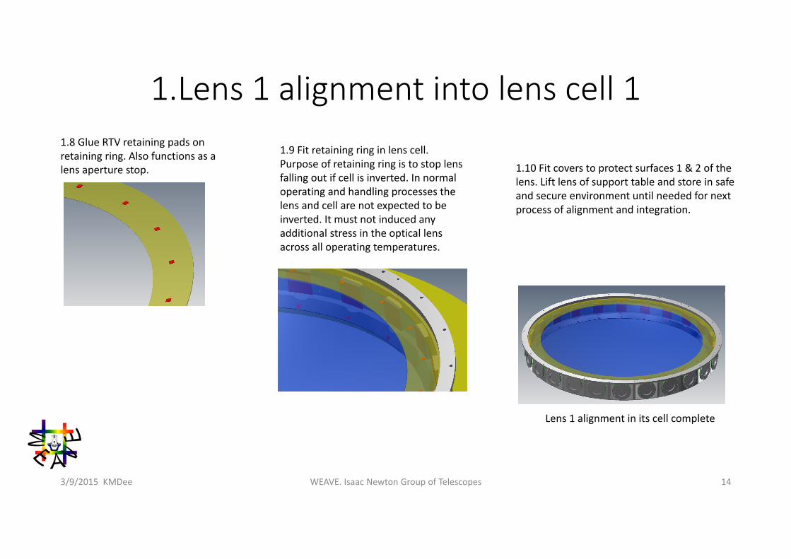
1.8 Glue RTV retaining pads on retaining ring. Also functions as a lens aperture stop.
1.9 Fit retaining ring in lens cell. Purpose of retaining ring is to stop lens falling out if cell is inverted. In normal operating and handling processes the lens and cell are not expected to be inverted. It must not induced any additional stress in the optical lens across all operating temperatures.
1.10 Fit covers to protect surfaces 1 & 2 of the lens. Lift lens of support table and store in safe and secure environment until needed for next process of alignment and integration.
Lens 1 alignment in its cell complete
2. Lens 2 alignment into lens cell 2
WEAVE. Isaac Newton Group of Telescopes 153/9/2015 KMDee
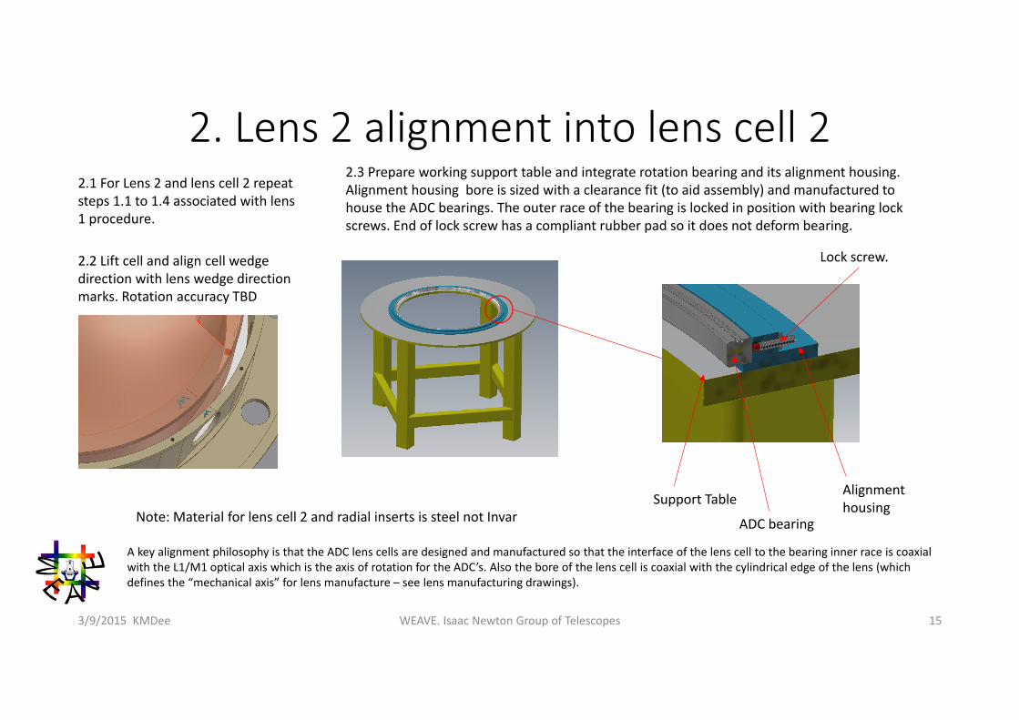
2.1 For Lens 2 and lens cell 2 repeat steps 1.1 to 1.4 associated with lens 1 procedure.
2.2 Lift cell and align cell wedge direction with lens wedge direction marks. Rotation accuracy TBD
2.3 Prepare working support table and integrate rotation bearing and its alignment housing. Alignment housing bore is sized with a clearance fit (to aid assembly) and manufactured to house the ADC bearings. The outer race of the bearing is locked in position with bearing lock screws. End of lock screw has a compliant rubber pad so it does not deform bearing.
Note: Material for lens cell 2 and radial inserts is steel not InvarSupport Table
ADC bearing
Alignment housing
A key alignment philosophy is that the ADC lens cells are designed and manufactured so that the interface of the lens cell to the bearing inner race is coaxial with the L1/M1 optical axis which is the axis of rotation for the ADC’s. Also the bore of the lens cell is coaxial with the cylindrical edge of the lens (which defines the “mechanical axis” for lens manufacture – see lens manufacturing drawings).
Lock screw.
2. Lens 2 alignment into lens cell 2
WEAVE. Isaac Newton Group of Telescopes 163/9/2015 KMDee
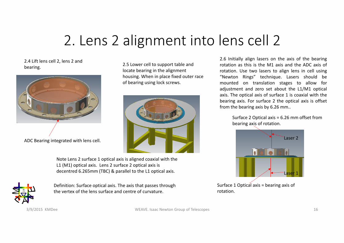
2.4 Lift lens cell 2, lens 2 and bearing. 2.5 Lower cell to support table and
locate bearing in the alignment housing. When in place fixed outer race of bearing using lock screws.
2.6 Initially align lasers on the axis of the bearingrotation as this is the M1 axis and the ADC axis ofrotation. Use two lasers to align lens in cell using“Newton Rings” technique. Lasers should bemounted on translation stages to allow foradjustment and zero set about the L1/M1 opticalaxis. The optical axis of surface 1 is coaxial with thebearing axis. For surface 2 the optical axis is offsetfrom the bearing axis by 6.26 mm..
Note Lens 2 surface 1 optical axis is aligned coaxial with the L1 (M1) optical axis. Lens 2 surface 2 optical axis is decentred 6.265mm (TBC) & parallel to the L1 optical axis.
ADC Bearing integrated with lens cell.
Surface 1 Optical axis = bearing axis of rotation.
Surface 2 Optical axis = 6.26 mm offset from bearing axis of rotation.
Laser 1
Laser 2
Definition: Surface optical axis. The axis that passes through the vertex of the lens surface and centre of curvature.
2. Lens 2 alignment into lens cell 2
WEAVE. Isaac Newton Group of Telescopes 173/9/2015 KMDee
Laser mounted on a translation stage
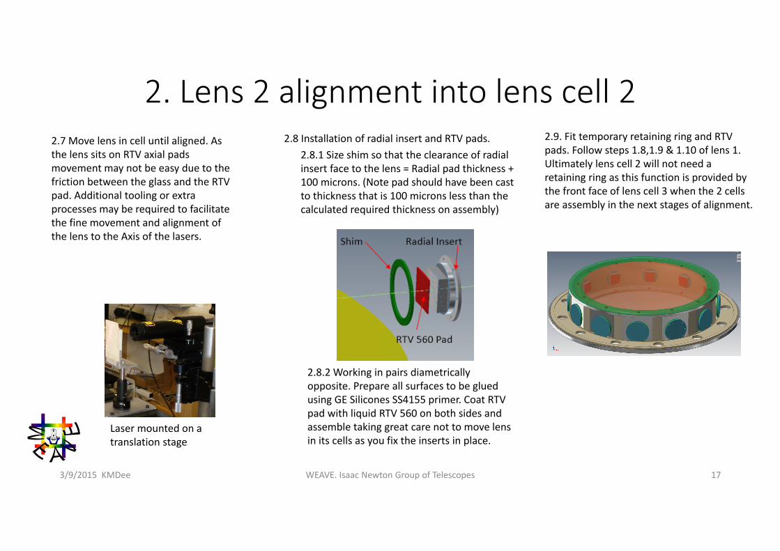
2.7 Move lens in cell until aligned. As the lens sits on RTV axial pads movement may not be easy due to the friction between the glass and the RTV pad. Additional tooling or extra processes may be required to facilitate the fine movement and alignment of the lens to the Axis of the lasers.
2.8 Installation of radial insert and RTV pads.2.8.1 Size shim so that the clearance of radial insert face to the lens = Radial pad thickness + 100 microns. (Note pad should have been cast to thickness that is 100 microns less than the calculated required thickness on assembly)
2.8.2 Working in pairs diametrically opposite. Prepare all surfaces to be glued using GE Silicones SS4155 primer. Coat RTV pad with liquid RTV 560 on both sides and assemble taking great care not to move lens in its cells as you fix the inserts in place.
2.9. Fit temporary retaining ring and RTV pads. Follow steps 1.8,1.9 & 1.10 of lens 1.Ultimately lens cell 2 will not need a retaining ring as this function is provided by the front face of lens cell 3 when the 2 cells are assembly in the next stages of alignment.
WEAVE. Isaac Newton Group of Telescopes 183/9/2015 KMDee
2,3,4 & 5 Tilted lenses Alignment Summary• The alignment of lens 2 in its cell presents a methodology to achieve alignment it is not a detailed description and requires development. There are obviously alternative methods to align the lenses in their cells.• The axis of the ADC bearings are nominally coaxial with the M1/L1 axis. The bearing rotation axis is the datum for alignment of tilted lens in their individual cells.• Lenses 2,3,4 & 5 of the ADC are tilted with respect to the M1/L1 optical axis. The optical axis's of Lens 2 surface 1 and lens 5 surface 2 are coaxial with the L1 axis. The optical axis's of surface 1 and surface 2 of both lens 3 and lens 4 are tilted with respect to the L1 optical axis.• Note all cells and inserts in the ADC are steel not INVAR
WEAVE. Isaac Newton Group of Telescopes 193/9/2015 KMDee
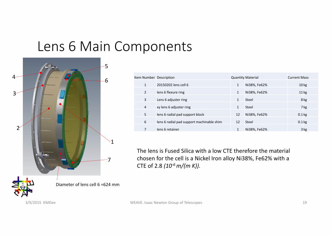
Lens 6 Main Components
Item Number Description Quantity Material Current Mass
1 20150202 lens cell 6 1 Ni38%, Fe62% 10kg
2 lens 6 flexure ring 1 Ni38%, Fe62% 11kg
3 Lens 6 adjuster ring 1 Steel 8 kg
4 xy lens 6 adjuster ring 1 Steel 7 kg
5 lens 6 radial pad support block 12 Ni38%, Fe62% 0.1 kg
6 lens 6 radial pad support machinable shim 12 Steel 0.1 kg
7 lens 6 retainer 1 Ni38%, Fe62% 3kg
1
7
6
5
2
3
4
Diameter of lens cell 6 =624 mm
The lens is Fused Silica with a low CTE therefore the material chosen for the cell is a Nickel Iron alloy Ni38%, Fe62% with a CTE of 2.8 (10‐6 m/(m K)).
WEAVE. Isaac Newton Group of Telescopes 203/9/2015 KMDee
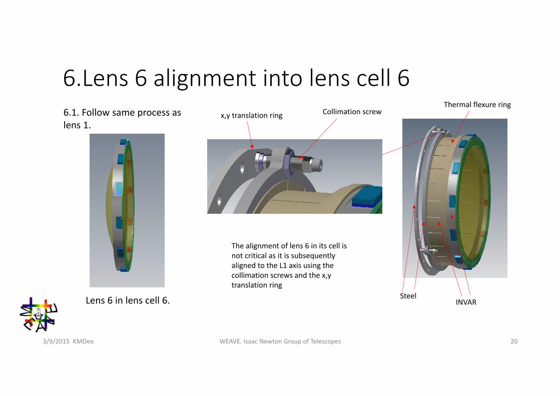
6.Lens 6 alignment into lens cell 66.1. Follow same process as lens 1.
Lens 6 in lens cell 6.
The alignment of lens 6 in its cell is not critical as it is subsequently aligned to the L1 axis using the collimation screws and the x,y translation ring
x,y translation ring Collimation screw
SteelINVAR
Thermal flexure ring
WEAVE. Isaac Newton Group of Telescopes 213/9/2015 KMDee
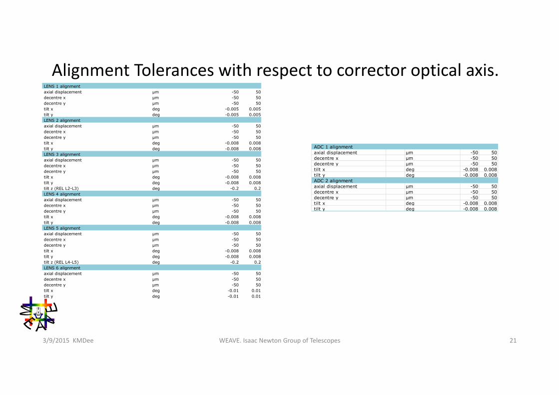
Alignment Tolerances with respect to corrector optical axis.LENS 1 alignmentaxial displacement µm -50 50decentre x µm -50 50decentre y µm -50 50tilt x deg -0.005 0.005tilt y deg -0.005 0.005LENS 2 alignmentaxial displacement µm -50 50decentre x µm -50 50decentre y µm -50 50tilt x deg -0.008 0.008tilt y deg -0.008 0.008LENS 3 alignmentaxial displacement µm -50 50decentre x µm -50 50decentre y µm -50 50tilt x deg -0.008 0.008tilt y deg -0.008 0.008tilt z (REL L2-L3) deg -0.2 0.2LENS 4 alignmentaxial displacement µm -50 50decentre x µm -50 50decentre y µm -50 50tilt x deg -0.008 0.008tilt y deg -0.008 0.008LENS 5 alignmentaxial displacement µm -50 50decentre x µm -50 50decentre y µm -50 50tilt x deg -0.008 0.008tilt y deg -0.008 0.008tilt z (REL L4-L5) deg -0.2 0.2LENS 6 alignmentaxial displacement µm -50 50decentre x µm -50 50decentre y µm -50 50tilt x deg -0.01 0.01tilt y deg -0.01 0.01
ADC 1 alignment axial displacement µm -50 50 decentre x µm -50 50 decentre y µm -50 50 tilt x deg -0.008 0.008 tilt y deg -0.008 0.008 ADC 2 alignment axial displacement µm -50 50 decentre x µm -50 50 decentre y µm -50 50 tilt x deg -0.008 0.008 tilt y deg -0.008 0.008
WEAVE. Isaac Newton Group of Telescopes 223/9/2015 KMDee
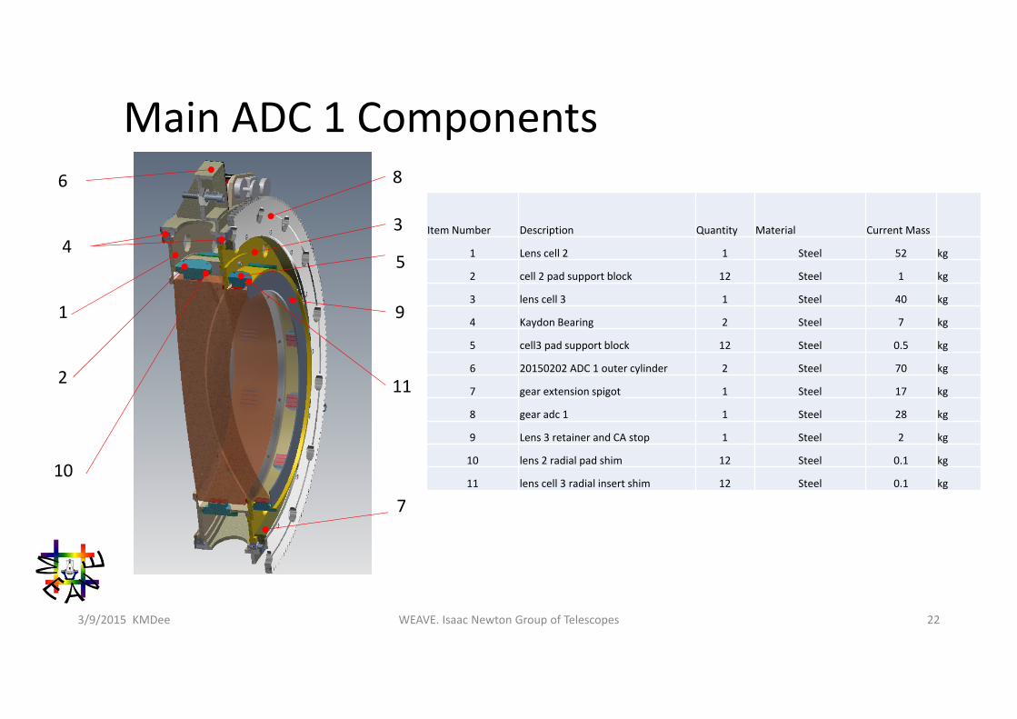
Item Number Description Quantity Material Current Mass
1 Lens cell 2 1 Steel 52 kg
2 cell 2 pad support block 12 Steel 1 kg
3 lens cell 3 1 Steel 40 kg
4 Kaydon Bearing 2 Steel 7 kg
5 cell3 pad support block 12 Steel 0.5 kg
6 20150202 ADC 1 outer cylinder 2 Steel 70 kg
7 gear extension spigot 1 Steel 17 kg
8 gear adc 1 1 Steel 28 kg
9 Lens 3 retainer and CA stop 1 Steel 2 kg
10 lens 2 radial pad shim 12 Steel 0.1 kg
11 lens cell 3 radial insert shim 12 Steel 0.1 kg
2
8
10
34
1
6
5
7
Main ADC 1 Components
9
11
WEAVE. Isaac Newton Group of Telescopes 233/9/2015 KMDee
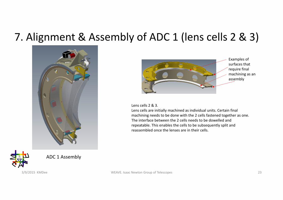
7. Alignment & Assembly of ADC 1 (lens cells 2 & 3)
Lens cells 2 & 3. Lens cells are initially machined as individual units. Certain final machining needs to be done with the 2 cells fastened together as one. The interface between the 2 cells needs to be dowelled and repeatable. This enables the cells to be subsequently split and reassembled once the lenses are in their cells.
Examples of surfaces that require final machining as an assembly
ADC 1 Assembly
WEAVE. Isaac Newton Group of Telescopes 243/9/2015 KMDee
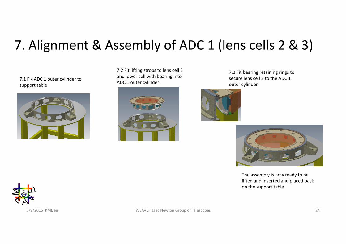
7. Alignment & Assembly of ADC 1 (lens cells 2 & 3)
7.1 Fix ADC 1 outer cylinder to support table
7.3 Fit bearing retaining rings to secure lens cell 2 to the ADC 1 outer cylinder.
7.2 Fit lifting strops to lens cell 2 and lower cell with bearing into ADC 1 outer cylinder
The assembly is now ready to be lifted and inverted and placed back on the support table
WEAVE. Isaac Newton Group of Telescopes 253/9/2015 KMDee
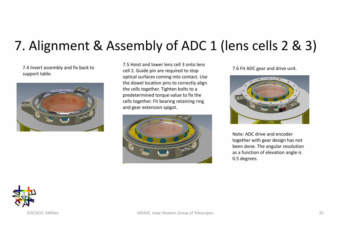
7. Alignment & Assembly of ADC 1 (lens cells 2 & 3)7.4 Invert assembly and fix back to support table.
7.5 Hoist and lower lens cell 3 onto lens cell 2. Guide pin are required to stop optical surfaces coming into contact. Use the dowel location pins to correctly align the cells together. Tighten bolts to a predetermined torque value to fix the cells together. Fit bearing retaining ring and gear extension spigot.
7.6 Fit ADC gear and drive unit.
Note: ADC drive and encoder together with gear design has not been done. The angular resolution as a function of elevation angle is 0.5 degrees.
WEAVE. Isaac Newton Group of Telescopes 263/9/2015 KMDee
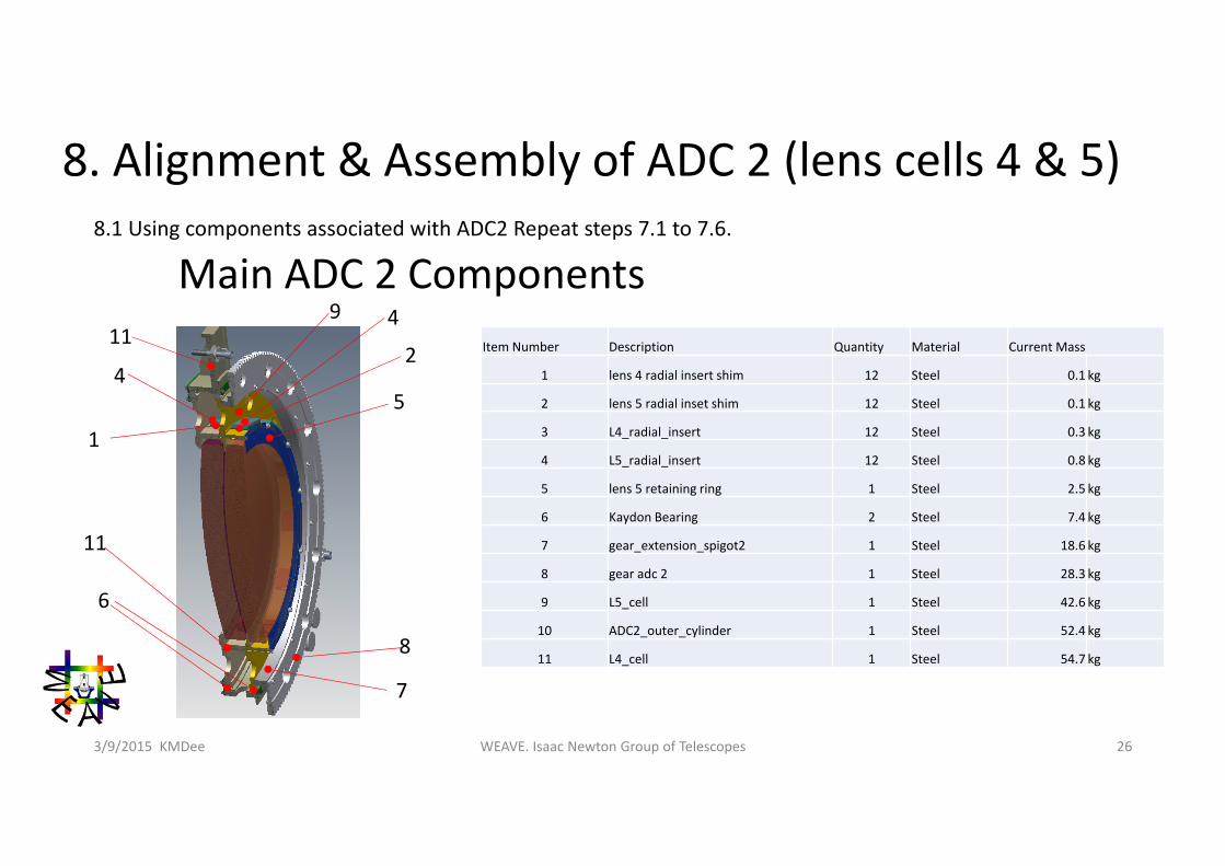
8. Alignment & Assembly of ADC 2 (lens cells 4 & 5)8.1 Using components associated with ADC2 Repeat steps 7.1 to 7.6.
Main ADC 2 ComponentsItem Number Description Quantity Material Current Mass
1 lens 4 radial insert shim 12 Steel 0.1 kg
2 lens 5 radial inset shim 12 Steel 0.1 kg
3 L4_radial_insert 12 Steel 0.3 kg
4 L5_radial_insert 12 Steel 0.8 kg
5 lens 5 retaining ring 1 Steel 2.5 kg
6 Kaydon Bearing 2 Steel 7.4 kg
7 gear_extension_spigot2 1 Steel 18.6 kg
8 gear adc 2 1 Steel 28.3 kg
9 L5_cell 1 Steel 42.6 kg
10 ADC2_outer_cylinder 1 Steel 52.4 kg
11 L4_cell 1 Steel 54.7 kg
7
4
5
1
42
6
8
9
11
11
WEAVE. Isaac Newton Group of Telescopes 273/9/2015 KMDee
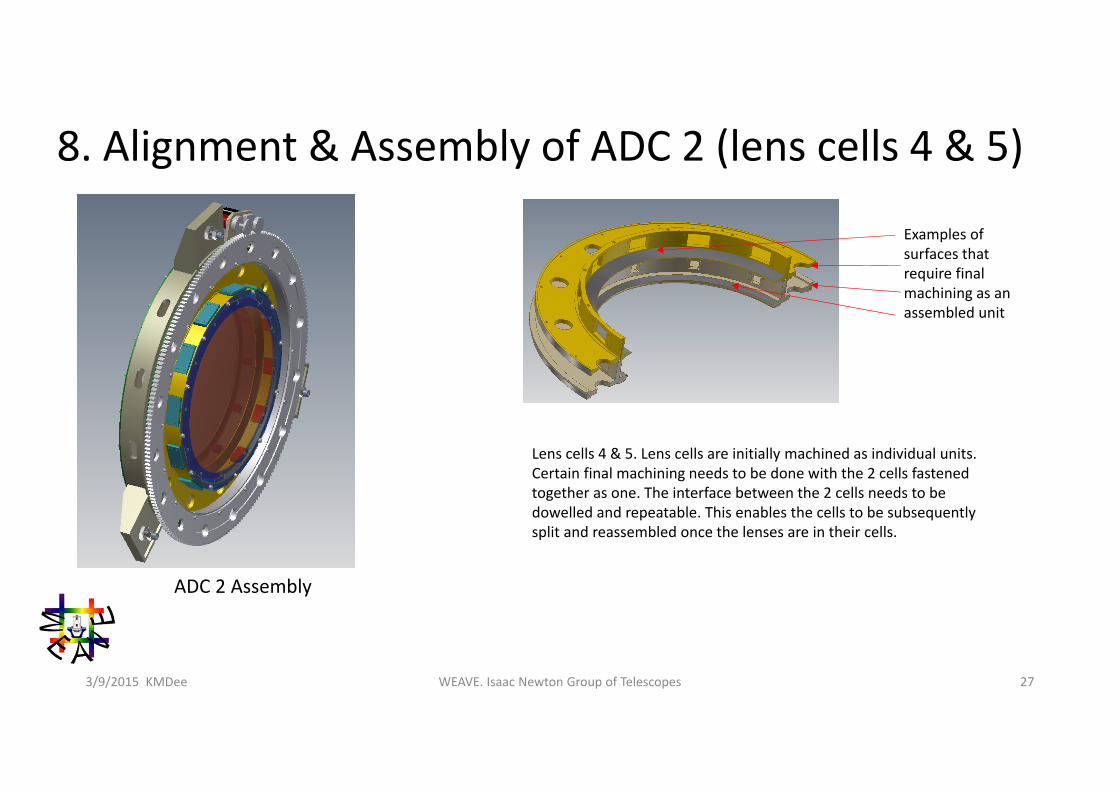
8. Alignment & Assembly of ADC 2 (lens cells 4 & 5)
Lens cells 4 & 5. Lens cells are initially machined as individual units. Certain final machining needs to be done with the 2 cells fastened together as one. The interface between the 2 cells needs to be dowelled and repeatable. This enables the cells to be subsequently split and reassembled once the lenses are in their cells.
Examples of surfaces that require final machining as an assembled unit
ADC 2 Assembly
WEAVE. Isaac Newton Group of Telescopes 283/9/2015 KMDee
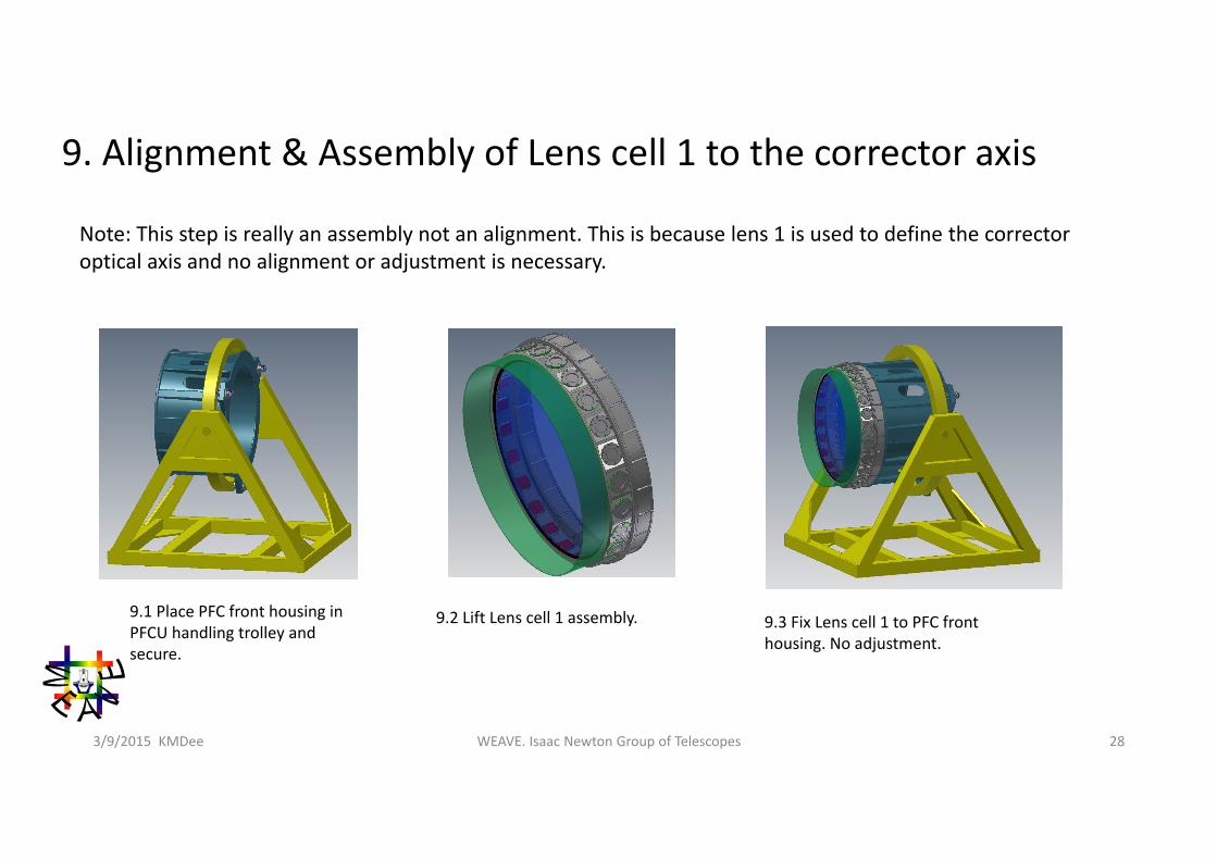
9. Alignment & Assembly of Lens cell 1 to the corrector axis
Note: This step is really an assembly not an alignment. This is because lens 1 is used to define the corrector optical axis and no alignment or adjustment is necessary.
9.1 Place PFC front housing in PFCU handling trolley and secure.
9.2 Lift Lens cell 1 assembly. 9.3 Fix Lens cell 1 to PFC front housing. No adjustment.
WEAVE. Isaac Newton Group of Telescopes 293/9/2015 KMDee
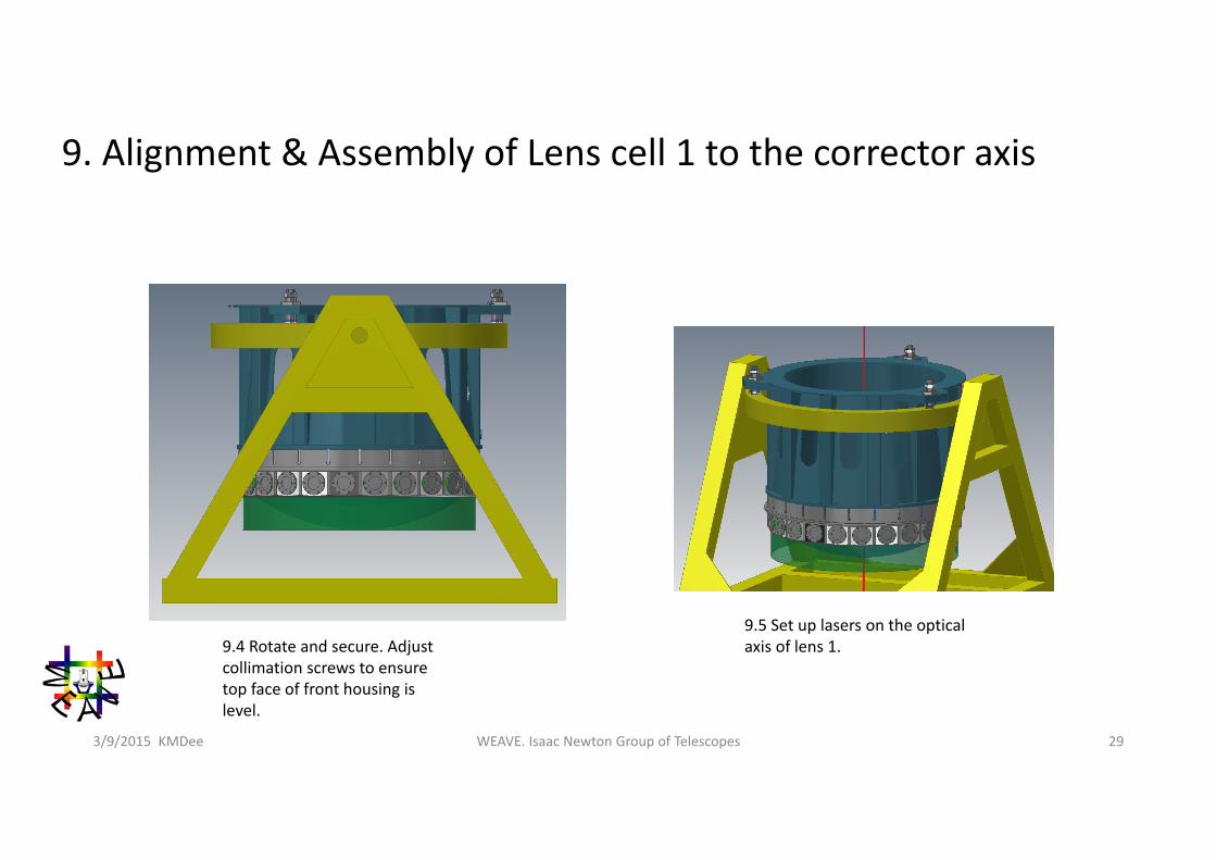
9. Alignment & Assembly of Lens cell 1 to the corrector axis
9.4 Rotate and secure. Adjust collimation screws to ensure top face of front housing is level.
9.5 Set up lasers on the optical axis of lens 1.
WEAVE. Isaac Newton Group of Telescopes 303/9/2015 KMDee
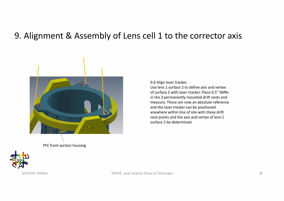
9. Alignment & Assembly of Lens cell 1 to the corrector axis
9.6 Align laser tracker.Use lens 1 surface 2 to define axis and vertex of surface 2 with laser tracker. Place 0.5” SMRs in the 3 permanently mounted drift nests and measure. These are now an absolute reference and the laser tracker can be positioned anywhere within line of site with these drift nest points and the axis and vertex of lens 1 surface 2 be determined.
PFC front section housing
WEAVE. Isaac Newton Group of Telescopes 313/9/2015 KMDee
10. ADC 1 alignment with L1 optical axis
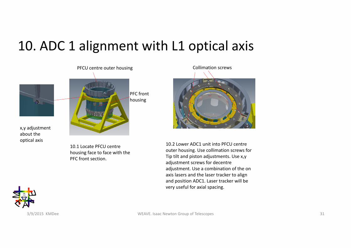
x,y adjustment about the optical axis
10.2 Lower ADC1 unit into PFCU centre outer housing. Use collimation screws for Tip tilt and piston adjustments. Use x,y adjustment screws for decentre adjustment. Use a combination of the on axis lasers and the laser tracker to align and position ADC1. Laser tracker will be very useful for axial spacing.
PFCU centre outer housing
10.1 Locate PFCU centre housing face to face with the PFC front section.
PFC front housing
Collimation screws
WEAVE. Isaac Newton Group of Telescopes 323/9/2015 KMDee
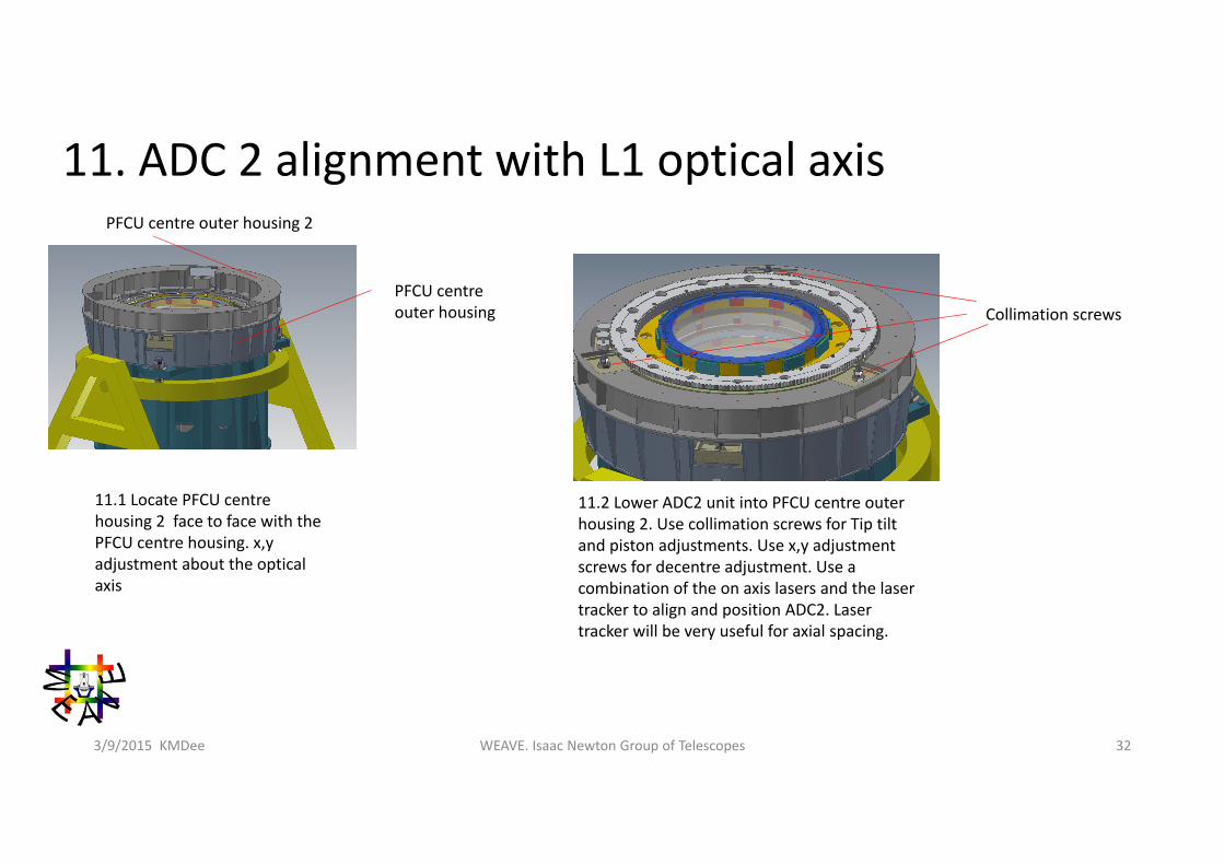
11. ADC 2 alignment with L1 optical axis
11.2 Lower ADC2 unit into PFCU centre outer housing 2. Use collimation screws for Tip tilt and piston adjustments. Use x,y adjustment screws for decentre adjustment. Use a combination of the on axis lasers and the laser tracker to align and position ADC2. Laser tracker will be very useful for axial spacing.
PFCU centre outer housing
11.1 Locate PFCU centre housing 2 face to face with the PFCU centre housing. x,y adjustment about the optical axis
Collimation screws
PFCU centre outer housing 2
WEAVE. Isaac Newton Group of Telescopes 333/9/2015 KMDee
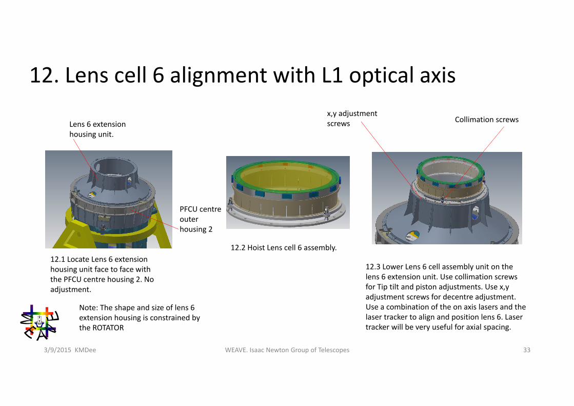
12. Lens cell 6 alignment with L1 optical axis
12.3 Lower Lens 6 cell assembly unit on the lens 6 extension unit. Use collimation screws for Tip tilt and piston adjustments. Use x,y adjustment screws for decentre adjustment. Use a combination of the on axis lasers and the laser tracker to align and position lens 6. Laser tracker will be very useful for axial spacing.
Lens 6 extension housing unit.
Collimation screws
PFCU centre outer housing 2
12.1 Locate Lens 6 extension housing unit face to face with the PFCU centre housing 2. No adjustment.
Note: The shape and size of lens 6 extension housing is constrained by the ROTATOR
12.2 Hoist Lens cell 6 assembly.
x,y adjustment screws
WEAVE. Isaac Newton Group of Telescopes 343/9/2015 KMDee
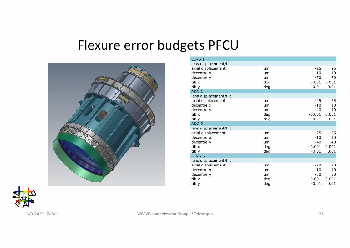
Flexure error budgets PFCULENS 1lens displacement/tiltaxial displacement µm -25 25decentre x µm -10 10decentre y µm -70 70tilt x deg -0.001 0.001tilt y deg -0.01 0.01ADC 1lens displacement/tiltaxial displacement µm -25 25decentre x µm -10 10decentre y µm -40 40tilt x deg -0.001 0.001tilt y deg -0.01 0.01ADC 2lens displacement/tiltaxial displacement µm -25 25decentre x µm -10 10decentre y µm -40 40tilt x deg -0.001 0.001tilt y deg -0.01 0.01LENS 6lens displacement/tiltaxial displacement µm -20 20decentre x µm -10 10decentre y µm -30 30tilt x deg -0.001 0.001tilt y deg -0.01 0.01
WEAVE. Isaac Newton Group of Telescopes 353/9/2015 KMDee
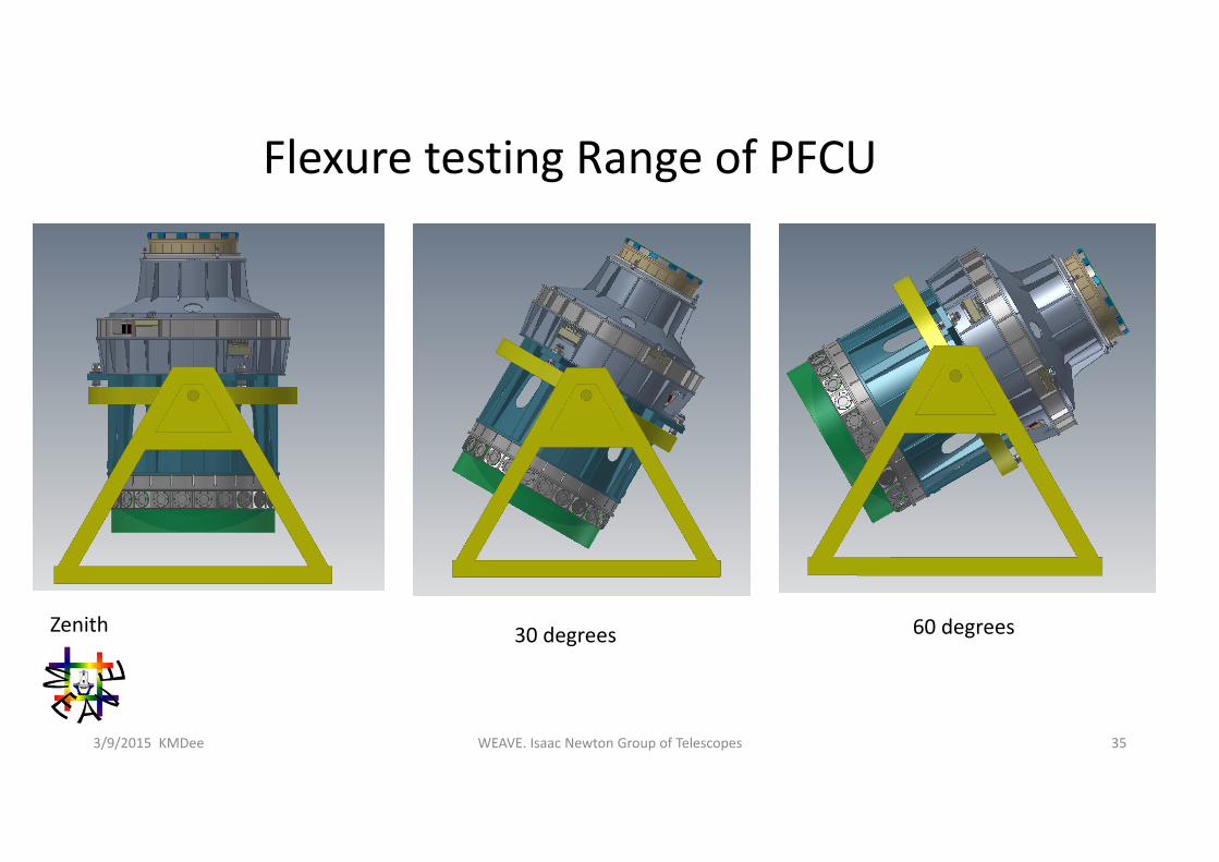
Flexure testing Range of PFCU
Zenith 30 degrees 60 degrees