Embed Size (px)
Citation preview
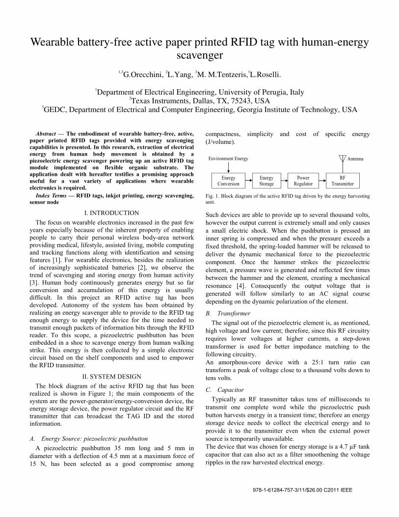
Wearable battery-free active paper printed RFID tag with human-energy scavenger
1,3G.Orecchini, 2L.Yang, 3M. M.Tentzeris,1L.Roselli.
1Department of Electrical Engineering, University of Perugia, Italy
2Texas Instruments, Dallas, TX, 75243, USA 3GEDC, Department of Electrical and Computer Engineering, Georgia Institute of Technology, USA
Abstract — The embodiment of wearable battery-free, active, paper printed RFID tags provided with energy scavenging capabilities is presented. In this research, extraction of electrical energy from human body movement is obtained by a piezoelectric energy scavenger powering up an active RFID tag module implemented on flexible organic substrate. The application dealt with hereafter testifies a promising approach useful for a vast variety of applications where wearable electronics is required.
Index Terms — RFID tags, inkjet printing, energy scavenging, sensor node
I. INTRODUCTION The focus on wearable electronics increased in the past few
years especially because of the inherent property of enabling people to carry their personal wireless body-area network providing medical, lifestyle, assisted living, mobile computing and tracking functions along with identification and sensing features [1]. For wearable electronics, besides the realization of increasingly sophisticated batteries [2], we observe the trend of scavenging and storing energy from human activity [3]. Human body continuously generates energy but so far conversion and accumulation of this energy is usually difficult. In this project an RFID active tag has been developed. Autonomy of the system has been obtained by realizing an energy scavenger able to provide to the RFID tag enough energy to supply the device for the time needed to transmit enough packets of information bits through the RFID reader. To this scope, a piezoelectric pushbutton has been embedded in a shoe to scavenge energy from human walking strike. This energy is then collected by a simple electronic circuit based on the shelf components and used to empower the RFID transmitter.
II. SYSTEM DESIGN The block diagram of the active RFID tag that has been
realized is shown in Figure 1; the main components of the system are the power-generator/energy-conversion device, the energy storage device, the power regulator circuit and the RF transmitter that can broadcast the TAG ID and the stored information.
A. Energy Source: piezoelectric pushbutton
A piezoelectric pushbutton 35 mm long and 5 mm in diameter with a deflection of 4.5 mm at a maximum force of 15 N, has been selected as a good compromise among
compactness, simplicity and cost of specific energy (J/volume).
Fig. 1. Block diagram of the active RFID tag driven by the energy harvesting unit. Such devices are able to provide up to several thousand volts, however the output current is extremely small and only causes a small electric shock. When the pushbutton is pressed an inner spring is compressed and when the pressure exceeds a fixed threshold, the spring-loaded hammer will be released to deliver the dynamic mechanical force to the piezoelectric component. Once the hammer strikes the piezoelectric element, a pressure wave is generated and reflected few times between the hammer and the element, creating a mechanical resonance [4]. Consequently the output voltage that is generated will follow similarly to an AC signal course depending on the dynamic polarization of the element.
B. Transformer The signal out of the piezoelectric element is, as mentioned,
high voltage and low current; therefore, since this RF circuitry requires lower voltages at higher currents, a step-down transformer is used for better impedance matching to the following circuitry. An amorphous-core device with a 25:1 turn ratio can transform a peak of voltage close to a thousand volts down to tens volts.
C. Capacitor Typically an RF transmitter takes tens of milliseconds to
transmit one complete word while the piezoelectric push button harvests energy in a transient time; therefore an energy storage device needs to collect the electrical energy and to provide it to the transmitter even when the external power source is temporarily unavailable. The device that was chosen for energy storage is a 4.7 µF tank capacitor that can also act as a filter smoothening the voltage ripples in the raw harvested electrical energy.
Energy Conversion
Energy Storage
Power Regulator
RF Transmitter
Environment Energy Antenna
978-1-61284-757-3/11/$26.00 C2011 IEEE
D. DC Linear Regulator An AC-DC full wave diode bridge rect
convert the AC voltage from piezoelectric esource and a DC linear regulator is added tvoltage across the capacitor to 3 V. To MAX666 low-dropout linear regulator, providsupply until the tank capacitor’s charge is drreference level of the DC linear regulator itsel
E. RF Transmitter The transmitter used (LINX TXE-433-KH2
active RFID tag; this component is housed in package and combines a highly optimized RFan on-board encoder.
III. SHOE-MOUNTED ANTENNA DAttentions have been paid to both the perf
aesthetic appearance of the antenna. The requirement of wearable electronicconsiderable design challenge in terms of technique. First the antenna needs to be confoshoe’s garment where no flat surface can unobtrusive, low-profile and comfortable totraditional rigid antennas are not applicable. Second, the 69 cm wavelength associated toband allocation at 433 MHz, requires theunobtrusive, low-profile and comfortable to wfar smaller than the wavelength. Third, the antenna needs to have robust perpresence of human body tissues because a grohardly incorporated into the shoe so the dehuman tissue must be accounted in the antennAs a proof-of-concept a design that uses a cproposed as a shoe-mounted antenna examsupposed to be stuck on the shoe so that nneeded for the antenna.
The antenna structure (Figure 2(a)) intrinsidipole, the center feeding is located in the band it will be connected to the output ptransmitter easily embedded and protected in tThe “radiating logo” appears on both sides oconnected to the central feeding by strip linesthe development the antenna is inkjet printeprinter on hydrophobic paper substrate [5].
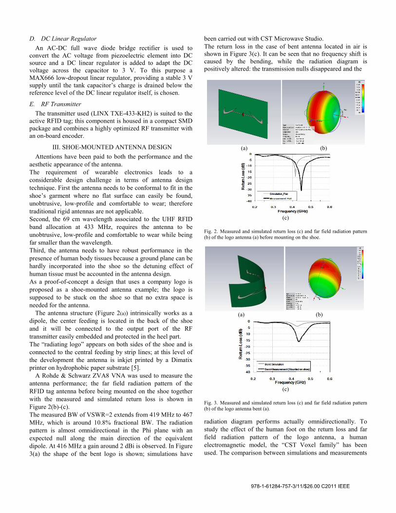
A Rohde & Schwarz ZVA8 VNA was useantenna performance; the far field radiationRFID tag antenna before being mounted on twith the measured and simulated return loFigure 2(b)-(c). The measured BW of VSWR=2 extends from MHz, which is around 10.8% fractional BWpattern is almost omnidirectional in the Phexpected null along the main direction ofdipole. At 416 MHz a gain around 2 dBi is ob3(a) the shape of the bent logo is shown; s
tifier is used to element into DC to adapt the DC
this purpose a ding a stable 3 V rained below the lf, is chosen.
2) is suited to the a compact SMD
F transmitter with
DESIGN formance and the
cs leads to a f antenna design ormal to fit in the easily be found,
o wear; therefore
o the UHF RFID e antenna to be wear while being
rformance in the ound plane can be etuning effect of
na design. company logo is
mple; the logo is no extra space is
ically works as a back of the shoe port of the RF the heel part. f the shoe and is s; at this level of ed by a Dimatix
d to measure the n pattern of the the shoe together oss is shown in
419 MHz to 467 W. The radiation hi plane with an f the equivalent
bserved. In Figure simulations have
been carried out with CST MicrowaThe return loss in the case of benshown in Figure 3(c). It can be seencaused by the bending, while positively altered: the transmission n
(a)
(c)
Fig. 2. Measured and simulated return loss (b) of the logo antenna (a) before mounting o
(a)
(c)
Fig. 3. Measured and simulated return loss (b) of the logo antenna bent (a). radiation diagram performs actuastudy the effect of the human footfield radiation pattern of the electromagnetic model, the “CSTused. The comparison between sim
ave Studio. nt antenna located in air is n that no frequency shift is the radiation diagram is nulls disappeared and the
(b)
(c) and far field radiation pattern on the shoe.
(b)
(c) and far field radiation pattern
ally omnidirectionally. To t on the return loss and far logo antenna, a human Voxel family” has been
mulations and measurements
978-1-61284-757-3/11/$26.00 C2011 IEEE
is shown in Figure 4(c). From the results shown in Figure 3 and 4 one can see that the presence of the human tissue causes a lower shift in the resonance frequency from around 430 MHz to 400 MHz; this is because the tissue works partially as a dielectric substrate for the antenna with a dielectric constant higher than the air that is the case of the sole bent paper antenna without foot behind it. The radiation pattern is shown in Figure 4(b); it can be observed that the presence of the foot increased slightly the directivity in the heel part of the shoe where the RFID tag and the central feeding lines of the antenna is placed. A slight variation of the radiation diagram is observed with the onset of a sort of main lobe with a directivity of 2.66 dBi; by the way, the overall omnidirectional behavior of the structure is retained.
(a) (b)
(c)
Fig. 4. Measured (foot in worn shoe) and simulated return loss of the logo antenna (electromagnetic model of foot).
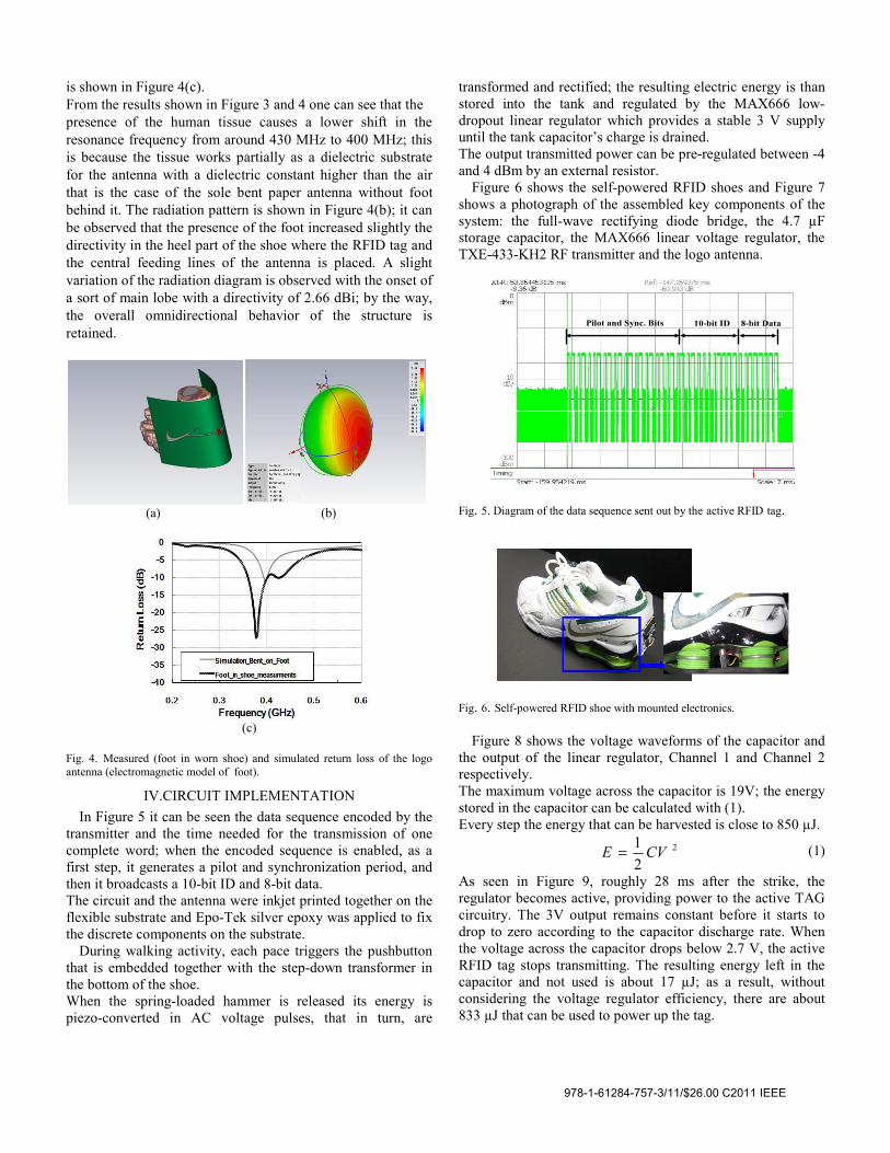
IV.CIRCUIT IMPLEMENTATION In Figure 5 it can be seen the data sequence encoded by the
transmitter and the time needed for the transmission of one complete word; when the encoded sequence is enabled, as a first step, it generates a pilot and synchronization period, and then it broadcasts a 10-bit ID and 8-bit data. The circuit and the antenna were inkjet printed together on the flexible substrate and Epo-Tek silver epoxy was applied to fix the discrete components on the substrate.
During walking activity, each pace triggers the pushbutton that is embedded together with the step-down transformer in the bottom of the shoe. When the spring-loaded hammer is released its energy is piezo-converted in AC voltage pulses, that in turn, are
transformed and rectified; the resulting electric energy is than stored into the tank and regulated by the MAX666 low-dropout linear regulator which provides a stable 3 V supply until the tank capacitor’s charge is drained. The output transmitted power can be pre-regulated between -4 and 4 dBm by an external resistor.
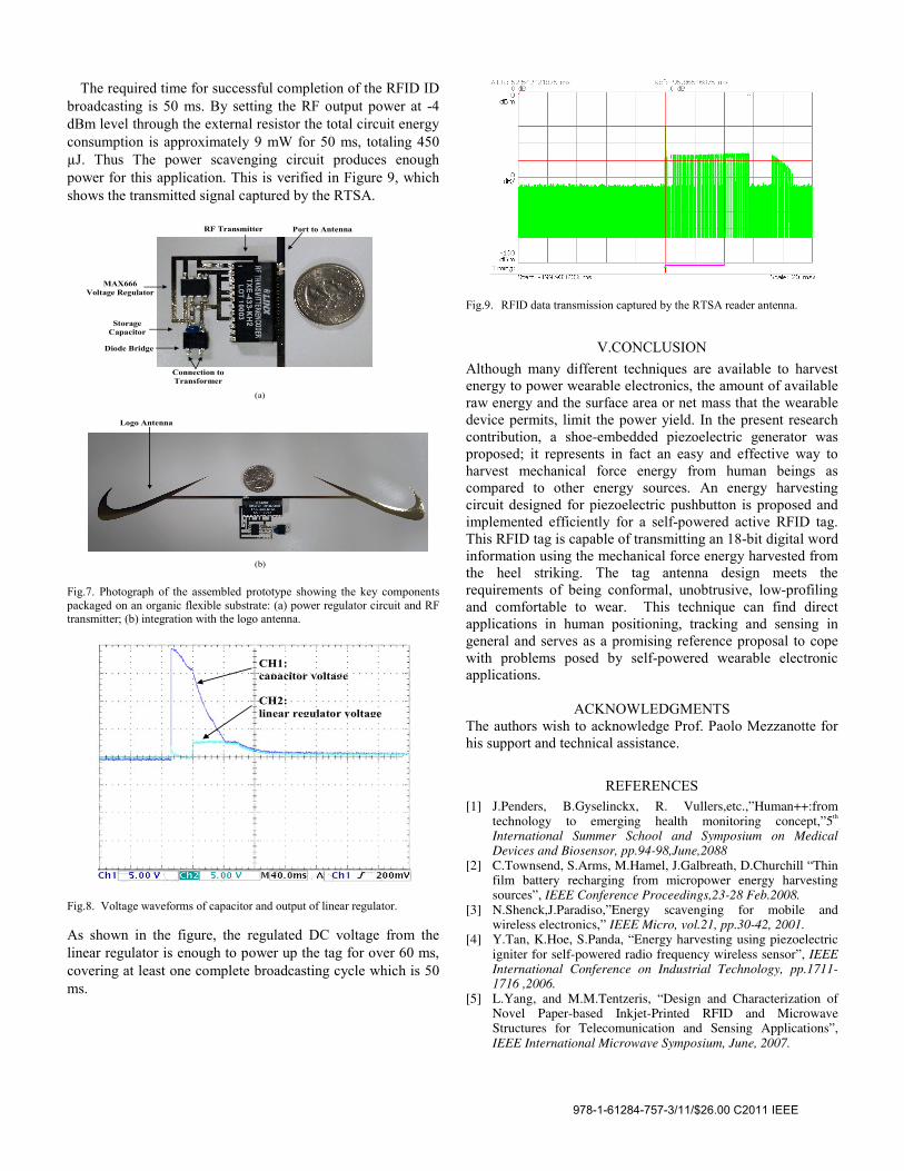
Figure 6 shows the self-powered RFID shoes and Figure 7 shows a photograph of the assembled key components of the system: the full-wave rectifying diode bridge, the 4.7 µF storage capacitor, the MAX666 linear voltage regulator, the TXE-433-KH2 RF transmitter and the logo antenna.
Fig. 5. Diagram of the data sequence sent out by the active RFID tag.
Fig. 6. Self-powered RFID shoe with mounted electronics.
Figure 8 shows the voltage waveforms of the capacitor and the output of the linear regulator, Channel 1 and Channel 2 respectively. The maximum voltage across the capacitor is 19V; the energy stored in the capacitor can be calculated with (1). Every step the energy that can be harvested is close to 850 µJ.
2
21 CVE =
(1)
As seen in Figure 9, roughly 28 ms after the strike, the regulator becomes active, providing power to the active TAG circuitry. The 3V output remains constant before it starts to drop to zero according to the capacitor discharge rate. When the voltage across the capacitor drops below 2.7 V, the active RFID tag stops transmitting. The resulting energy left in the capacitor and not used is about 17 µJ; as a result, without considering the voltage regulator efficiency, there are about 833 µJ that can be used to power up the tag.
10-bit ID 8-bit Data Pilot and Sync. Bits
978-1-61284-757-3/11/$26.00 C2011 IEEE
The required time for successful completion of the RFID ID broadcasting is 50 ms. By setting the RF output power at -4 dBm level through the external resistor the total circuit energy consumption is approximately 9 mW for 50 ms, totaling 450 µJ. Thus The power scavenging circuit produces enough power for this application. This is verified in Figure 9, which shows the transmitted signal captured by the RTSA.
Fig.7. Photograph of the assembled prototype showing the key components packaged on an organic flexible substrate: (a) power regulator circuit and RF transmitter; (b) integration with the logo antenna.
Fig.8. Voltage waveforms of capacitor and output of linear regulator. As shown in the figure, the regulated DC voltage from the linear regulator is enough to power up the tag for over 60 ms, covering at least one complete broadcasting cycle which is 50 ms.
Fig.9. RFID data transmission captured by the RTSA reader antenna.
V.CONCLUSION Although many different techniques are available to harvest energy to power wearable electronics, the amount of available raw energy and the surface area or net mass that the wearable device permits, limit the power yield. In the present research contribution, a shoe-embedded piezoelectric generator was proposed; it represents in fact an easy and effective way to harvest mechanical force energy from human beings as compared to other energy sources. An energy harvesting circuit designed for piezoelectric pushbutton is proposed and implemented efficiently for a self-powered active RFID tag. This RFID tag is capable of transmitting an 18-bit digital word information using the mechanical force energy harvested from the heel striking. The tag antenna design meets the requirements of being conformal, unobtrusive, low-profiling and comfortable to wear. This technique can find direct applications in human positioning, tracking and sensing in general and serves as a promising reference proposal to cope with problems posed by self-powered wearable electronic applications.
ACKNOWLEDGMENTS The authors wish to acknowledge Prof. Paolo Mezzanotte for his support and technical assistance.
REFERENCES [1] J.Penders, B.Gyselinckx, R. Vullers,etc.,”Human++:from
technology to emerging health monitoring concept,”5th International Summer School and Symposium on Medical Devices and Biosensor, pp.94-98,June,2088
[2] C.Townsend, S.Arms, M.Hamel, J.Galbreath, D.Churchill “Thin film battery recharging from micropower energy harvesting sources”, IEEE Conference Proceedings,23-28 Feb.2008.
[3] N.Shenck,J.Paradiso,”Energy scavenging for mobile and wireless electronics,” IEEE Micro, vol.21, pp.30-42, 2001.
[4] Y.Tan, K.Hoe, S.Panda, “Energy harvesting using piezoelectric igniter for self-powered radio frequency wireless sensor”, IEEE International Conference on Industrial Technology, pp.1711-1716 ,2006.
[5] L.Yang, and M.M.Tentzeris, “Design and Characterization of Novel Paper-based Inkjet-Printed RFID and Microwave Structures for Telecomunication and Sensing Applications”, IEEE International Microwave Symposium, June, 2007.
Diode Bridge
Storage Capacitor
MAX666 Voltage Regulator
RF Transmitter Port to Antenna
Connection to Transformer
Logo Antenna
(a)
(b)
CH1: capacitor voltage
CH2: linear regulator voltage
978-1-61284-757-3/11/$26.00 C2011 IEEE