Embed Size (px)
Citation preview

Wear 252 (2002) 644–653
Wear mechanism of metal bond diamond wheels truedby wire electrical discharge machining
Brian K. Rhoneya, Albert J. Shiha,∗, Ronald O. Scattergoodb,Ronald Ottc, Samuel B. McSpaddenc
a Department of Mechanical and Aerospace Engineering, North Carolina State University, Raleigh, NC 27695, USAb Department of Materials Science and Engineering, North Carolina State University, Raleigh, NC 27695, USA
c High Temperature Materials Laboratory, Oak Ridge National Laboratory, Oak Ridge, TN 37831, USA
Received 9 July 2001; received in revised form 15 January 2002; accepted 23 January 2002
Abstract
The stereographic scanning electron microscopy (SEM) imaging was used to investigate the wear mechanism in wire electrical dischargemachining (EDM) truing of metal bond diamond wheels for ceramic grinding. A piece of the grinding wheel was removed after truingand grinding to enable the examination of wheel surface and measurement of diamond protrusion heights using a SEM and stereographicimaging software. The stereographic SEM imaging method was calibrated by comparing with the profilometer measurement results. Onthe wheel surface after wire EDM truing and before grinding, some diamond grain protruding heights were measured in the 32�m level.Comparing to the 54�m average size of the diamond grain, this indicated that over half of the diamond was exposed. During the wire EDMprocess, electrical sparks occur between the metal bond and EDM wire, which leaves the diamond protruded in the gap between the wireelectrode and wheel. These protruding diamond grains with weak bond to the wheel were fractured under a light grinding condition. Afterheavy grinding, the diamond protrusion heights were estimated in the 5–15�m range above the wear flat. A cavity created by grindingdebris erosion wear of the wheel bond could be identified around the diamond grain. © 2002 Published by Elsevier Science B.V.
Keywords: Scanning electron microscopy (SEM); Diamond wheels; Electrical discharge machining (EDM); Grinding wheel wear
1. Introduction
Diamond wheels are used extensively in grinding of engi-neering ceramics for structural and electronic applications.To achieve the desired form accuracy and surface integrityon ground parts, diamond wheels are usually wear-resistantand difficult to shape or true to the desired geometry [1].The electrical discharge machining (EDM) process has beenapplied to generate the precise form on metal bond diamondwheels using either the die-sink [2–7] or wire [8] EDM con-figurations. At the start of grinding, a high wheel wear ratewas observed on metal bond diamond wheels trued by theEDM process. The wheel wear rate was significantly lowerin subsequent grinding [8]. The goal of this research is tostudy the wear mechanism of the wire EDM trued diamondwheels for ceramic grinding.
Advancements in three-dimensional stereo image analysisusing the scanning electron microscopy (SEM) have madeit an ideal tool to examine the surface topography of metalbond diamond wheels. By applying computer image analysis
∗ Corresponding author. Tel.:+1-919-515-5260; fax:+1-919-515-7968.E-mail address: [email protected] (A.J. Shih).
to a pair of SEM images, a topographic representation ofthe grinding wheel surface can be obtained. The height ofdiamond protrusion from the wheel surface after wire EDMtruing and after grinding can be quantified using the stereo-graphic SEM imaging analysis. SEM examinations of grind-ing wheel surfaces and comparison of diamond protrusionheights at different levels of grinding can reveal the wearmechanism for wire EDM trued metal bond diamond wheels.
An early application of stereographic SEM imagingmethod was presented by Lee and Russ [9] for the metrol-ogy of microelectronic devices. Syoji et al. [10] appliedthe stereographic SEM imaging to measure the protru-sion height of abrasive grains on a metal bond diamondwheel and to correlate the measured results to grindingperformance. Zhao et al. [11] used the stereographic SEMimaging to study the shape of cutting edges on surfaces ofa resinoid bond CBN wheel and to observe the effect oftruing parameters on CBN grains.
The diamond wheel used in this study consists of an elec-trically conductive metal bond and the non-electrically con-ductive diamond grain. During the EDM truing, electricalsparks are generated around the diamond to erode the metalbond and cause the whole diamond grain to fall out from the
0043-1648/02/$ – see front matter © 2002 Published by Elsevier Science B.V.PII: S0043-1648(02)00019-4

B.K. Rhoney et al. / Wear 252 (2002) 644–653 645
Fig. 1. Schematic illustration of the EDM wire, rotating diamond wheel,the gap between wire and wheel, and the protrusion of the diamond grainson the wheel surface.
wheel surface [8]. During the wire EDM process, as shownin Fig. 1, a gap in the 35�m level exists between the wireelectrode and rotating diamond wheel. The diamond grainprotrudes out of the wheel surface by a height close to orslightly less than the gap distance. This theory is examinedby using the stereographic SEM imaging to measure the di-amond protrusion height on wheel surface.
In this paper, the preparation of the diamond wheelsurface with different conditions for SEM study is firstintroduced. The procedures for using the SEM to generatethree-dimensional topographical data and calibrating thestereographic SEM measurement are then presented. Threeconditions of the wheel surface:
Fig. 2. The grinding wheel surface and the preparation of three areas with different levels of truing and grinding for stereographic SEM imaging study.
1. after wire EDM without grinding,2. after one pass of grinding with 0.127 mm down feed, and3. after 100 passes of grinding with 0.127 mm down feed,
are prepared and quantified using the stereographic SEMimaging method. A wheel wear mechanism was proposedbased on the observation.
2. Grinding wheel preparation
The 200 mm diameter grinding wheel was too big tobe observed using the SEM. After grinding, a piece onthe wheel surface, as shown in the front view Fig. 2, wasremoved from the wheel and examined using the SEM.The truing of the grinding wheel was conducted usinga Brother HS-5100 wire EDM machine. After truing, asshown in the side view in Fig. 2, the wheel was used togrind the sintered silicon nitride (TSN-10 by Toshiba) us-ing a Harig 618 grinding machine. The table speed was50.8 mm/s, wheel surface speed was 37 m/s, and length ofthe part ground was 21.7 mm. In each grinding pass, thedown feed was 0.127 mm and specific material removal ratewas 6.46 mm3/mm s. The middle section of the grindingwheel surface was worn by only a single pass of grind-ing of Workpiece #1, i.e.t1 = 0.127 mm in the side viewFig. 2. Workpiece #2 was ground by 99 passes, each with0.127 mm down feed, to wear the left section of the wheelin the side view by heavy grinding. Thet2 in Fig. 2 was12.573 mm.
In summary, three areas were generated on the wheel sur-face. These three areas were: (1) after wire EDM withoutgrinding, (2) after light grinding with one pass of 0.127 mmdown feed and (3) after heavy grinding with 100 passes of0.127 mm down feed.

646 B.K. Rhoney et al. / Wear 252 (2002) 644–653
3. Stereo scanning electron microscope
The stereographic SEM imaging is a measurement toolused in this study. This section discusses the procedure togenerate the surface topography using stereographic SEMimaging and the calibration of this measurement method.
3.1. Procedure for stereo SEM
A Hitachi S-4700 field emission SEM was used in thisstudy. This SEM was selected due to the automated stagepositioning and tilting features, which were required for con-structing a three-dimensional topographic image of the sur-face. First, an SEM image of the surface was taken with thestage set at zero degree tilt. A feature that could be relo-cated again, once the table was tilted, was then marked onthe image. Once this feature was identified, the stage wastilted by a specific small angle, two degrees in this case.Another SEM image was taken. This image was then trans-lated to bring the original marked feature back to match theoriginal position in the first image. By knowing the work
Fig. 3. Calibration of the stereographic SEM measurement method using a wear groove: (a) SEM micrograph of the wear groove and the starting andending points of a line segment, (b) stereo representation of the surface and (c) comparison of the wear groove measured using the Talysurf profilometerand stereographic SEM imaging methods.
distance and the pixel size, these two images could be com-bined using the AliconaTM imaging software to constructa three-dimensional image of the surface. Several line seg-ments were drawn on the SEM image and the software cal-culated and created a chart to show the change in height onpixels along these line segments.
3.2. Calibration
As shown in Fig. 3, a wear groove about 200�m wideand 12�m deep was used as a standard sample to calibratethe stereographic SEM imaging method. The SEM micro-graph of the groove and a line segment across the grooveare shown in Fig. 3a. The procedure presented in Section3.1 was applied to generate the stereo representation of thesurface, as shown in Fig. 3b. The same groove was alsomeasured using the Talysurf profilometer with diamond tipcontact stylus. Comparisons of these two measurement re-sults are shown in Fig. 3c. The two closely matched tracesverified and calibrated the stereographic SEM measurementused in this study.

B.K. Rhoney et al. / Wear 252 (2002) 644–653 647
Fig. 4. (a–e) SEM micrographs of the grinding wheel surface after wire EDM without grinding.
4. Diamond wheel surface after wire EDM truing
The first area to be observed using stereographic SEMimaging was the wheel surface after EDM truing withoutgrinding. SEM micrographs of the wheel surface are shownin Fig. 4. As shown in the overall view in Fig. 4c, the surfacewas rough with sparsely and evenly distributed diamondgrains. Some metal bond material has been resolidified orrecasted to the wheel surface. It is noted that these recastsare strongly bonded to the wheel surface, despite the useof a high-pressure jet of deionized water during wire EDMtruing and the ultrasonic cleaning before examining in theSEM.
Two types of metal resolidification can be identified onthe wheel surface. The first type is the recast sphere, whichis the molten metal bond that did not escape the gap duringEDM spark erosion and was resolidified on the wheel sur-face. Examples of the recast sphere are indicated in Fig. 4band d. The second type is the splashed recast, as shown byexamples in Fig. 4a and e. The splash in Fig. 4e is furthermagnified in Fig. 5a. This type of recast is possibly due tothe collision of the single spark eroded molten metal with thediamond and then splashing and resolidifying layer-by-layeron the surface close to a diamond grain. Figs. 4e and 5ashow that several layers of splashed recast can occur. Thisindicates that the splash occurs at different time during the

648 B.K. Rhoney et al. / Wear 252 (2002) 644–653
Fig. 5. The height of diamond protrusion on the wire EDM wheel surface without grinding: (a) the diamond grain in Fig. 4e and (b) the diamond grainin Fig. 4b.
wire EDM truing. Besides these recasts, diamond grains ex-posed out of the wheel surface can also be observed. Theprotrusion height of these diamond grains is measured usingthe stereographic SEM imaging method.
Fig. 5a shows the enlarged view of the diamond grainin Fig. 4e. Three line segments were selected on the SEMimage to measure the protrusion height of the diamondgrain. The AliconaTM three-dimensional imaging softwarewas used to construct a stereo image of this surface and tocalculate the variation of height along pixels on these threeline segments. The measurement trace starts from a pointmarked by s and ends at the point e. Two or three otherpoints, marked by a–c, are used as the intermediate markersto link the position on measured height trace to the point onSEM image.
Results of the height variation are shown in the trace belowSEM micrographs. The diamond grain in Fig. 5a protrudesover the surrounding metal matrix by about 29�m. Fig. 5bshows another diamond grain, the one boxed in Fig. 4b,protruding out of the surrounding surface by about 32�m.
The average size of the 325 ANSI mesh diamond grainin the wheel is about 54�m. Results in Fig. 5 indicatethat after wire EDM truing, many diamond grains onwheel surface have exposed over half of their size out-side the surrounding metal bond. Section 5 will showthat these over-protruded diamond grains are expectedto fracture or pull out of the wheel surface after lightgrinding. It is noted that not all the diamond grains areprotruding in the 30�m level. Other diamond protru-sion heights, in the range of 6–20�m, have been mea-sured. Some of these diamond grains may not be frac-tured and become active for material removal duringgrinding.
The hypothesis of the fracture of over-protruded diamondgrains after light grinding can support the wear measure-ment results presented in the wheel wear study [8]. The ini-tially high wear rate on the wire EDM trued metal bonddiamond wheel surface can be caused by the fracture ofover-protruding diamond grains. Fig. 5a and b also demon-strate the advantage of using the stereographic SEM as a

B.K. Rhoney et al. / Wear 252 (2002) 644–653 649
metrology tool to quantify the diamond protrusion height ongrinding wheel surface.
5. Wear of the diamond wheel surfaceafter light grinding
SEM micrographs of the wheel surface after one passgrinding of silicon nitride with 0.127 mm down feed areshown in Fig. 6. The spherical and splashed recasts, whichoriginally bonded to the wheel surface after EDM truing,were mostly disappeared. Some diamond grains had beenpulled out and left a cavity on the wheel surface, as indicated
Fig. 6. (a–e) SEM micrographs of the wheel surface after light grinding.
in Fig. 6c and e. Some of the diamond grains exhibitedfractured surfaces, such as those marked in Fig. 6a and b.Wear flat areas on the metal bond, such as those shown inFig. 6a and c–e, were created after light grinding. Thesewear flats were used as the datum for stereographic SEMmeasurement of diamond protrusion heights.
Fig. 7 shows results of two diamond protrusion heightmeasurements. The starting point of the line, marked by s,was located on a wear flat, which was set as the datum formeasurement. The straight-line segment in Fig. 7a crossedthe two diamond grains shown in Fig. 6d. The first diamondgrain, marked by b, had about the same height as the wearflat. The second diamond grain, marked by c, was about
650 B.K. Rhoney et al. / Wear 252 (2002) 644–653
Fig. 7. The height of diamond protrusion on the wheel surface after light grinding: (a) the two diamond grains in Fig. 6d and (b) the diamond grain inFig. 6e.
6�m above the wear flat. Both diamond grains showed rubmarks on the surface and appeared to be active in grind-ing. Another example illustrated the active diamond grain inFig. 6e, which is marked as point b in Fig. 7b, had about thesame height as the datum wear flat surface. Fig. 7 and othermeasurement traces on the wheel surface after light grindingconcluded diamond grains protruding above the wear flat byabout 6–12�m after light grinding.
6. Wear of the diamond wheel surfaceafter heavy grinding
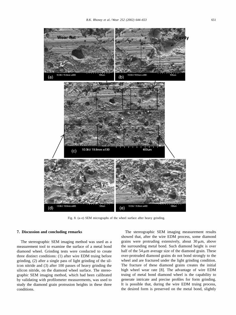
The wheel surface after 100 grinding passes of 0.127 mmdown feed, or 100 times more work-material removed thanthe light grinding presented in Section 5, was studied. SEMmicrographs of the wheel surface after such heavy grindingare shown in Fig. 8. Comparing to Fig. 6c, relatively largerwear flat areas could be seen in Fig. 8c. The cavity createdby diamond grain pull out, as indicated in Fig. 8b and c,could be identified.
The diamond grain located in the middle of a large wearflat area shown in Fig. 8b was studied using the stereographicSEM imaging method. Fig. 9a showed a line starting andending both on the wear flat. The diamond grain, indicatedby b, was protruding about 5�m over the wear flat. A cav-ity in front of the diamond grain, about 4�m deep, couldbe observed. As illustrated in Fig. 10, the grinding debriseroded the bond in front of the diamond grain during grind-ing and generated a cavity. For grinding ceramics, the useof debris for erosion wear of the wheel bond in front of di-amond grain has been reported [12]. This is a technology toself-dress or self-sharpen of wheels for efficient grinding ofceramics.
Another diamond grain, not shown in Fig. 8, was studiedusing the stereographic SEM imaging method. As shownin Fig. 9b, this diamond grain, marked by b, is protrud-ing over the wear flat by about 13�m. A cavity in frontof this diamond grain could also be identified in Fig. 9b.Fig. 9 and other measurements showed diamond grains areprotruding about 5–15�m above the wear flat after heavygrinding.
B.K. Rhoney et al. / Wear 252 (2002) 644–653 651
Fig. 8. (a–e) SEM micrographs of the wheel surface after heavy grinding.
7. Discussion and concluding remarks
The stereographic SEM imaging method was used as ameasurement tool to examine the surface of a metal bonddiamond wheel. Grinding tests were conducted to createthree distinct conditions: (1) after wire EDM truing beforegrinding, (2) after a single pass of light grinding of the sil-icon nitride and (3) after 100 passes of heavy grinding thesilicon nitride, on the diamond wheel surface. The stereo-graphic SEM imaging method, which had been calibratedby validating with profilometer measurements, was used tostudy the diamond grain protrusion heights in these threeconditions.
The stereographic SEM imaging measurement resultsshowed that, after the wire EDM process, some diamondgrains were protruding extensively, about 30�m, abovethe surrounding metal bond. Such diamond height is overhalf of the 54�m average size of the diamond grain. Theseover-protruded diamond grains do not bond strongly to thewheel and are fractured under the light grinding condition.The fracture of these diamond grains creates the initialhigh wheel wear rate [8]. The advantage of wire EDMtruing of metal bond diamond wheel is the capability togenerate intricate and precise profiles for form grinding.It is possible that, during the wire EDM truing process,the desired form is preserved on the metal bond, slightly

652 B.K. Rhoney et al. / Wear 252 (2002) 644–653
Fig. 9. The height of diamond protrusion on the wheel surface after heavy grinding: (a) the diamond grain in Fig. 8b and (b) a diamond grain protrudedfrom the wear flat.
below the tip of over-protruding diamond grains. This isespecially important for the precision form grinding usingEDM trued diamond wheels. More studies are required tofurther validate this hypothesis.
Benefits of using the stereographic SEM imaging as ameasurement tool have been demonstrated in this study.Heights of diamond protrusion are very difficult to quantifyusing the contact profilometer method. The stereographicSEM imaging method can be applied to other research ar-eas to study the topography of rough surfaces that are eithertoo small or difficult to be measured using the stylus contactprobing method.
Fig. 10. The grinding debris erosion of a cavity in front of the diamondgrain.
Acknowledgements
The authors gratefully acknowledge the support byNational Science Foundation Grant #9983582 (Dr. K.P.Rajurkar, Program Director). Support for this research wasalso provided by the Assistant Secretary for Energy Ef-ficiency and Renewable Energy, Office of TransportationTechnologies, as part of the High Temperature MaterialsLaboratory User Program, Oak Ridge National Laboratory,managed by UT-Battelle, LLC, for the US Department ofEnergy under Contract no. DE-AC05-00OR22725.
References
[1] A.J. Shih, Rotary truing of the vitreous bond diamond grindingwheels using metal bond diamond disks, Machining Sci. Technol. 2(1998) 13–28.
[2] K. Suzuki, T. Uematsu, T. Nakagawa, On-machine truing/dressing ofmetal bond diamond grinding wheels by electro-discharge machining,Ann. CIRP 36 (1) (1987) 115–118.
[3] K. Suzuki, T. Uematsu, T. Yanase, T. Nakagawa, On-machineelectro-discharge truing for metal bond diamond grinding wheelsfor ceramics, in: S. Jahanmir (Ed.), Proceedings of the International

B.K. Rhoney et al. / Wear 252 (2002) 644–653 653
Conference on Machining of Advanced Materials, NIST SpecialPublication 847, Gaithersburg, MD, 20–22 July 1993, pp. 83–88.
[4] X. Wang, B. Ying, W. Liu, EDM dressing of fine grain superabrasive grinding wheel, J. Mater. Process. Technol. 62 (1996) 299–302.
[5] K. Sato, T. Yokoyama, K. Suzuki, Production of electrodepositeddiamond wheels and grinding performance for hard metals andceramics, J. Mater. Process. Technol. 62 (1996) 303–308.
[6] J. Qian, W. Li, H. Ohmori, Precision internal grinding with a metal-bonded diamond grinding wheel, J. Mater. Process. Technol. 105(2000) 80–86.
[7] C. Zhang, H. Ohmori, W. Li, Small-hole machining of ceramicmaterial with electrolytic interval-dressing (ELID-II) grinding, J.Mater. Process. Technol. 105 (2000) 284–289.
[8] B.K. Rhoney, A.J. Shih, R.O. Scattergood, J.L. Akemon, D.J. Gust,M.B. Grant, Cylindrical wire electrical discharge machining of
metal bond diamond wheels, Int. J. Machine Tool Manufac., inpress.
[9] J.H. Lee, J.C. Russ, Metrology of microelectronic devices by stereoSEM, J. Comput. Assisted Microsc. 1 (1) (1989) 79–90.
[10] K. Syoji, L. Zhou, S. Matsui, Studies on truing and dressing ofdiamond wheels (1st report): the measurement of protrusion height ofabrasive grains by using a stereo pair and the influence of protrusionheight on grinding performance, Bull. Jpn. Soc. Precis. Eng. 24 (2)(1990) 124–129.
[11] X. Zhao, K. Syoji, T. Kuriyagawa, L. Zhou, Truing of resinoid-bonded CBN wheels (1st report, cutting edge shape after truing),Trans. Jpn. Soc. Mech. Eng. Part C 62 (601) (1996) 3725–3730.
[12] A.J. Shih, T.M. Yonushonis, High infeed rate method for grindingceramic workpiece with silicon carbide grinding wheels, US Patent6,030,277 (2000).