Embed Size (px)
Citation preview
MULTIDISCIPLINARY CENTER FOR EARTHQUAKE ENGINEERING RESEARCH
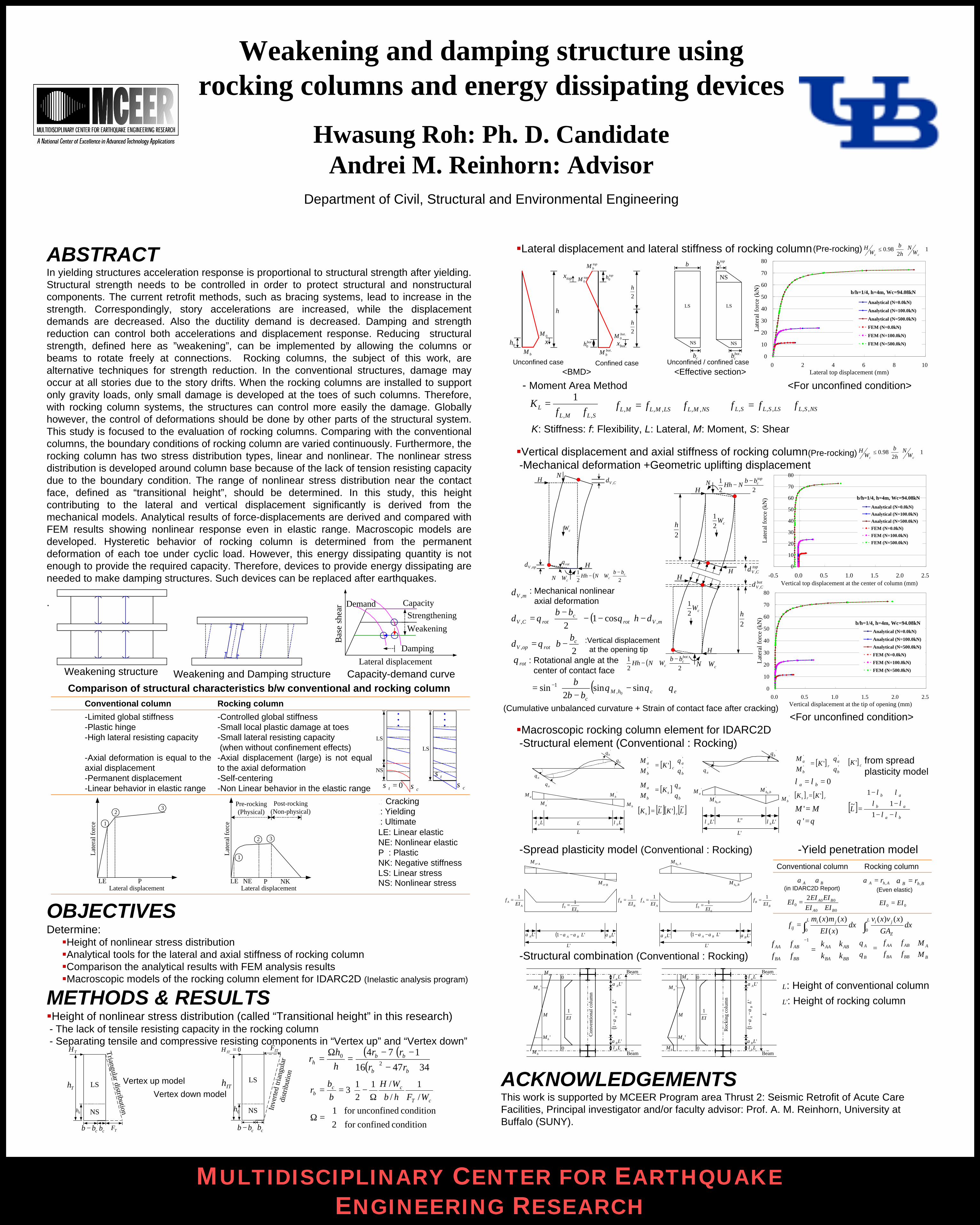
Weakening and damping structure using rocking columns and energy dissipating devices
Hwasung Roh: Ph. D. CandidateAndrei M. Reinhorn: Advisor
Department of Civil, Structural and Environmental Engineering
ABSTRACTIn yielding structures acceleration response is proportional to structural strength after yielding. Structural strength needs to be controlled in order to protect structural and nonstructural components. The current retrofit methods, such as bracing systems, lead to increase in the strength. Correspondingly, story accelerations are increased, while the displacement demands are decreased. Also the ductility demand is decreased. Damping and strength reduction can control both accelerations and displacement response. Reducing structural strength, defined here as ”weakening”, can be implemented by allowing the columns or beams to rotate freely at connections. Rocking columns, the subject of this work, are alternative techniques for strength reduction. In the conventional structures, damage may occur at all stories due to the story drifts. When the rocking columns are installed to support only gravity loads, only small damage is developed at the toes of such columns. Therefore, with rocking column systems, the structures can control more easily the damage. Globally however, the control of deformations should be done by other parts of the structural system. This study is focused to the evaluation of rocking columns. Comparing with the conventional columns, the boundary conditions of rocking column are varied continuously. Furthermore, the rocking column has two stress distribution types, linear and nonlinear. The nonlinear stress distribution is developed around column base because of the lack of tension resisting capacity due to the boundary condition. The range of nonlinear stress distribution near the contact face, defined as “transitional height”, should be determined. In this study, this height contributing to the lateral and vertical displacement significantly is derived from the mechanical models. Analytical results of force-displacements are derived and compared with FEM results showing nonlinear response even in elastic range. Macroscopic models are developed. Hysteretic behavior of rocking column is determined from the permanent deformation of each toe under cyclic load. However, this energy dissipating quantity is not enough to provide the required capacity. Therefore, devices to provide energy dissipating are needed to make damping structures. Such devices can be replaced after earthquakes.
.
Comparison of structural characteristics b/w conventional and rocking column
OBJECTIVESDetermine:§Height of nonlinear stress distribution§Analytical tools for the lateral and axial stiffness of rocking column§Comparison the analytical results with FEM analysis results§Macroscopic models of the rocking column element for IDARC2D (Inelastic analysis program)
METHODS & RESULTS§Height of nonlinear stress distribution (called “Transitional height” in this research)- The lack of tensile resisting capacity in the rocking column- Separating tensile and compressive resisting components in “Vertex up” and “Vertex down”
§Lateral displacement and lateral stiffness of rocking column
- Moment Area Method <For unconfined condition>
§Vertical displacement and axial stiffness of rocking column-Mechanical deformation +Geometric uplifting displacement
<For unconfined condition>§Macroscopic rocking column element for IDARC2D-Structural element (Conventional : Rocking)
-Spread plasticity model (Conventional : Rocking) -Yield penetration model
-Structural combination (Conventional : Rocking)
ACKNOWLEDGEMENTSThis work is supported by MCEER Program area Thrust 2: Seismic Retrofit of Acute Care Facilities, Principal investigator and/or faculty advisor: Prof. A. M. Reinhorn, University at Buffalo (SUNY).
<BMD>
Cracking: Yielding: UltimateLE: Linear elasticNE: Nonlinear elasticP : PlasticNK: Negative stiffnessLS: Linear stressNS: Nonlinear stress
-Controlled global stiffness-Small local plastic damage at toes-Small lateral resisting capacity(when without confinement effects) -Axial displacement (large) is not equal to the axial deformation-Self-centering-Non Linear behavior in the elastic range
-Limited global stiffness-Plastic hinge-High lateral resisting capacity
-Axial deformation is equal to the axial displacement-Permanent displacement-Linear behavior in elastic range
Rocking columnConventional column
PLELateral displacement
Lat
eral
forc
e 1
23
ITF
Inve
rted
trian
gula
rdi
strib
utio
n
0=ITH
0h
cbcbb −
ITh
NS
LS
( )( )( ) 344716
1742
0
+−
−−=
Ω=∴
bb
bbh
rr
rrhh
r
<Effective section>
both0
toph0
2h
2h
.botbM
0h
h
bM
0Mx
.0botM
topM 0
topbM
.botx
topx
cb
b
LS
NS
.botcb
LS
NS
topcb
NS
NSMLLSMLML fff ,,,,, += NSSLLSSLSL fff ,,,,, +=SLML
L ffK
,,
1+
=
cW
cWN +
H( )
221 c
c
bbWNHh
−+−
HN
CV ,δ
opV ,δ rotθ
( ) mVrotc
rotCV hbb
,, cos12
δθθδ −−−
−
=
−=
2,c
rotopV
bbθδ
rotθ : Rotational angle at thecenter of contact face
(Cumulative unbalanced curvature + Strain of contact face after cracking)
aθ'
aθ
'bθ
bθ
'LLaλ Lbλ
aM'
aM
'bM
bM
L
'aM
'bM
'aθ
'bθ
"L'Laλ 'Lbλ
',0 bhM
',0 ahM
'L
[ ]
=
'
'
'
'
'b
ac
b
a KMM
θθ
[ ]
=
b
as
b
a KMM
θθ
[ ] [ ][ ] [ ]LKLK cs~
'~
=
[ ]
=
'
'
'
'
'b
ar
b
a KMM
θθ
0== ba λλ
[ ] [ ] rrs KK '=
MM ='θθ ='
[ ] cK ' from spread plasticity model
[ ]ba
ab
ab
Lλλ
λλλλ
−−
−
−
=1
11
~
'LAα 'LBα
AA EI
f1
=
AcrM
BcrM
00
1EI
f = BB EI
f1
=
( ) '1 LBA αα −−
'L
AhM ,0
BhM ,0
00
1EI
f =
'LAα
'L
AA EI
f1
=B
B EIf
1=
'LBα( ) '1 LBA αα −−∫∫ +=
L
Z
jiL jiij dx
GA
xvxvdx
xEI
xmxmf
00
)()(
)(
)()(
=
B
A
BBBA
ABAA
B
A
MM
ffff
θθ
=
−
BBBA
ABAA
BBBA
ABAA
kkkk
ffff 1
Laλ'LAα
Lbλ'LBα
()
'1
LB
Aα
α−
−
L
EI1
0
0
M
Con
vent
iona
l col
umn
'aM
'bM
aM Beam
BeambM
Aα Bα
00
000
2
BA
BA
EIEIEIEI
EI+
=
AhA r ,=α BhB r ,=α
00 EIEI =
Rocking columnConventional column
Laλ'LAα
Lbλ'LBα
()
'1
LB
Aα
α−
−
L
EI1
0
0
M
Roc
king
col
umn
'aM
'bM
aM
bM
Beam
Beam
L
'L
: Height of conventional column: Height of rocking column
Vertex up model
Vertex down model
(in IDARC2D Report)
Unconfined case Confined case Unconfined / confined case
mV ,δ : Mechanical nonlinearaxial deformation
K: Stiffness: f: Flexibility, L: Lateral, M: Moment, S: Shear
=Ωcondition confinedfor 2
condition unconfinedfor 1
( ) εθθθ +
−
−= −
chMcbb
bsinsin
2sin
0,1
0
10
20
30
40
50
60
70
80
-0.5 0.0 0.5 1.0 1.5 2.0 2.5Vertical top displacement at the center of column (mm)
Lat
eral
forc
e (k
N)
Analytical (N=0.0kN)
Analytical (N=100.0kN)
Analytical (N=500.0kN)
FEM (N=0.0kN)
FEM (N=100.0kN)
FEM (N=500.0kN)
b/h=1/4, h=4m, Wc=94.08kN
0
10
20
30
40
50
60
70
80
0 2 4 6 8 10Lateral top displacement (mm)
Lat
eral
forc
e (k
N)
Analytical (N=0.0kN)
Analytical (N=100.0kN)
Analytical (N=500.0kN)
FEM (N=0.0kN)
FEM (N=100.0kN)
FEM (N=500.0kN)
b/h=1/4, h=4m, Wc=94.08kN
+≤ 1
298.0
cc WN
hb
WH(Pre-rocking)
(Pre-rocking)
+≤ 1
298.0
cc WN
hb
WH
:Vertical displacementat the opening tip
0
10
20
30
40
50
60
70
80
0.0 0.5 1.0 1.5 2.0 2.5Vertical displacement at the tip of opening (mm)
Lat
eral
forc
e (k
N)
Analytical (N=0.0kN)
Analytical (N=100.0kN)
Analytical (N=500.0kN)
FEM (N=0.0kN)
FEM (N=100.0kN)
FEM (N=500.0kN)
b/h=1/4, h=4m, Wc=94.08kN
TF
0h
TH
cbcbb −
Th LS
NS
Triangular distribution
topCV ,δ
botCV ,δ
2h
2h
N
cWN +
H
HH
H
221 top
cbbNHh
−−
cW21
cW21
( )22
1 .botc
cbb
WNHh−
+−
(Even elastic)
Ω
−==cT
ccb WFhb
WHbb
r/1
//1
21
3
Lateral displacementLE NE P
Lat
eral
forc
e
1
2 3
Pre-rocking(Physical)
Post-rocking(Non-physical)
NK
Weakening structure Weakening and Damping structure Capacity-demand curve
StrengtheningWeakening
DampingLateral displacement
Bas
e sh
ear Demand Capacity
cσtσ
0=tσ
NS
LS
LS
cσ