Embed Size (px)
Citation preview

IN THIS ISSUE:
“We would like to thank all of you, who participated in our anniversary celebrations and confirmed the global recognition we enjoy. We are proud to have earned the
long-term confidence and trust of all of you.”
Dear reader,
The party is over!
After the week-long celebration of our 100th anniversary at the beginning of September, we are back at work. We are proud that so many of you could participate and show the long-term confi dence and trust you all have in our work. We promise to continue carrying on in the tradition of conducting research and development beyond the current state of technology. It is our strategy to meet your needs by continuously improving our tools – both, the experimental and the numerical ones – but also with the development of new equipment and facilities.
At present, our daily work shows no sign of slowing down. Rising requirements lead to more precise and challenging technical specifi cations which, in turn, demand increasingly complex testing under high pressure circumstances, not only in open water but also more and more in ice covered environments. Future markets will require
extraordinary levels of ingenuity, skills and commitment. Each project still is unique and the selection of the specifi c numerical tool and the necessary model tests should be made in close cooperation with our experts.
In these times, networking, knowledge exchange and marketing are of fundamental importance for us to keep our position in the world. We need to meet you: our clients, partners and colleagues all over the world. I hope this will happen during the next months. There will be several chances to meet our experts and discuss all your questions related to ship and offshore hydrodynamics in open water and in ice. Events will be the meeting of the German Society of Naval Architects STG in Berlin, and the MARINTEC 2013 in Shanghai, China. Our team is prepared to answer any question you may have.
Juergen Friesch - Managing DirectorMARINTEC CHINA 2013
• 100 years HSVA – Thank You for Celebrating with Us
• Asymetric Rudder Bulb Design for Energy Saving
• On Nice Views Through Small Holes
• Not Just a Cosmetic Nose Job – the ES-Bow of the CSBC Corporation, Taiwan
• CFD Recaps 80 Year Old Model Tests for Transatlantic Liners
• A New Control and Propulsion System (SAS) for Seakeeping Tests
• Simulation of Ice Management Operations
• A New Search-and-Rescue Cruiser Class at HSVA
• A New Towing Arrangement for Measurement of Wave Added Resistance in Oblique Seas
• Member of Staff
• TITANIC II Model Test Held at HSVA

Thank You for Celebrating with Us
Between the 9th and 13th of September this year, HSVA celebrated its 100th anniversary. The celebrations started on Monday with a reception of the Hamburg Senate in the house of the Patriotic Society of Hamburg, the old City Hall, with 160 guests.On Tuesday, a symposium took place, with various presentations and a discussion on “Shipping in the Future” as well as a dinner high above the rooftops of Hamburg, with about 240 participants.On Wednesday afternoon the people of HSVA, together with our customers celebrated a barbecue on the site of the Model Basin. Again, more than 160 friends came.Starting on Thursday afternoon, we celebrated the anniversary with our retired people with a party that ended for some of us not before the early Friday morning.At the end of the week the doors of the model basin were opened for the people of Hamburg. On that open day at the site of the Model Basin in Hamburg-Barmbek 1400 visitors took the chance to look at the different facilities and watch some tests.
Newswave 2
100 years

Thank You for Celebrating with Us1913 – 2013


Newswave 11
During the offi cial celebrations on Monday and Tuesday, offi cial welcome addresses were given by the First Mayor of Hamburg, Dr. Olaf Scholz; Frank Horch, Senator of Economics, Innovation and Transport in Hamburg; Dr. Herbert Aly, Chairman of the Supervisory Board of HSVA; Dr. Gerhard Strasser, Chairman of the International Towing Tank Con-ference – ITTC; Dr. Graham Clarke, Director of the European Council for Maritime Applied R&D – ECMAR.Speeches were given by Niels Kaiser, representative of the German ship owner Norddeutsche Reederei H. Schuldt, Dr. Po Fan Chen, representing the shipyard CSBC Corpo-ration in Taiwan and Dr. Hugo J. Heerema, representing Bluewater Energy Services BV in The Netherlands.During the round table discussion Dr. Bas Buchner from MARIN, the model basin in the Netherlands, Prof. Stefan Krüger of the Technical University of Hamburg-Harburg, Dr. Carsten Wiebers from KfW IPEX-Bank GmbH in Frankfurt and Jacob Buus Petersen from the classifi cation society ABS in Denmark expressed their opinions on the future of our business.
Newswave 5

Newswave 6
Asymetric Rudder Bulb Design for Energy Saving
by Yan Xing-Kaeding & Scott Gatchell
The development of Energy Saving Devices (ESDs) is a hot topic in the maritime industry. These energy savings directly translate into reduced fuel costs and improved environ-mental impact. The diffi culty in the develop-ment is determining the most suitable design for the given ship and operating condition(s).
Within the GRIP project (an FP7 EU project with 11 partners, introduced already in
Newswave 2012/01) HSVA is leading Work Package 5: “Designing Customised ESDs”. In this work package, a fully automated design and optimisation cycle including parametric ESD modelling, grid generation and RANS propulsion prediction has been established to obtain an optimised ESD design.
It is well known that optimisations utilizing RANS methods are quite computationally intensive (i.e. expensive), especially when a large number of design parameters are
involved. This is normally the case for an ESD model. Restricting the parameters means restricting the design space, which may not always be desirable due to the risk of fi nding only a local optimum.
An alternative approach is to utilize the adjoint-based sensitivity analysis by reversing the RANS equations to pursue the sensitivity of the geometry based on a prescribed objective function using fl ow variables. This approach, which has
Fig. 1: Rotational energy by tangential fl ow comparing the cases without (left) and with rudder bulb (right)
Fig. 2: Computed surface sensitivities using the rotational energy as objective function: Starboard view (left), port view (right)

Newswave 7
been presented already in the previous issue of Newswave for the case of a bulk carrier aftbody, helps to identify the design variables that have the greatest impact, in order to reduce the search space to a more manageable number of variables, with lower risk of missing the global optimum.
It is, however, not trivial to defi ne an objective function that leads to an optimised design of ESD, due to the complexity of hull-propeller-ESD interaction. Finding the working principle of each ESD is therefore of great importance and is also one of the aims of the GRIP project.
The adjoint solver has been newly developed into the HSVA in-house RANS code FreSCo+ thanks to several research projects. One example is now presented here showing how the adjoint analysis has inspired an asymmetric rudder bulb design for energy saving. Figure 1 shows the rotational energy of the tangential fl ow behind the propeller due to the presence of the rudder bulb.By using this rotational energy as the objective function, the sensitivities on the surface of the hull, rudder and bulb in Figure 2 strongly
suggest an asymmetric rudder bulb as well as a twisted rudder. The surface sensitivities can in principle be transformed into the parameter sensitivities, which leads to an asymmetric rudder bulb, shown in Figure 3.
The computed streamlines through the propeller hub region, shown in Figure 4,
confi rm that the so-called propeller hub vortex has been largely eliminated due to the presence of the rudder bulb. The fi nal results predict an energy saving of 2.7% in the case of an asymmetric rudder bulb and 1.6% if the bulb stays axis-symmetric.
Fig. 4: Computed streamlines through the propeller hub region: Without (left) and with rudder bulb (right)
Fig. 3: Asymmetric design of rudder bulb: Profi le view (left) yellow indicates cross section location comparing red asymmetric bulb to black circular section (right)

Newswave 8
On Nice Views Through Small Holes
by Christian Johannsen
The latest generation of miniature video cameras allows full scale cavi-tation observations with much better quality just through a small bore in the shell plating.
Two years ago HSVA’s NewsWave issue 2011/1 explained in much detail the constraints and compromises one had to live with when planning cavitation observations on a real ship. At that time good quality pictures of propeller cavitation required large observation windows to be mounted in the shell either already during the building phase of the vessel or subsequently in a dry dock. The only possibility to avoid those windows was to use a so-called boroscope, shifted outboards through a small bore in the shell. This boroscope, a stiff kind of endoscope with fi ber optics and a camera on top, swallowed a huge amount of light. Slow shutter speeds of the camera and motion blur were the consequences. At a typical shutter speed of 1/25 sec for the camera on top of the boroscope, the blade tip of a 9 m container ship propeller advanced by 1.7 m during each single frame was taken.
But times have changed! HSVA has recently invested in the latest generation of miniature video cameras. This camera is small enough to be placed watertight at the end of a steel tube with the same dimensions as the boroscope. The procedure is easy:
• On short notice the shell plating of the ship gets a number of M20 threaded holes above the propeller. This can easily be done in any harbor from inside when the ship is trimmed to lift this part of the shell above the water line. • Special HSVA-provided stop cock units are screwed in to close the openings.• For the investigations just one HSVA technician gets onboard to shift the new camera through the stop cock unit outboards at sea without spilling one drop.• High quality pictures are recorded by the miniature camera within an hour and without complex artifi cial lighting installations. • If necessary, the same openings can be used a minute later to measure the pressure pulses generated by the working propeller.
Fig. 1 shows the new equipment recently installed in the shell plating of a 16,000 TEU
container vessel. Fig. 2 shows a number of pictures taken with this observation equipment, illuminated by not more than a weakly clouded sky.
Of course, the pictures cannot compete with the sharpness of pictures taken at stroboscopic light. The motion freezing effect of 5 µsec strobe fl ash is absolutely unbeatable. Nevertheless, the interesting phenomena – back sheet and tip vortex cavitation here in this case – are clearly visible. So whenever trouble shooting or a small budget require for a quick and easy solution, HSVA‘s new full scale observation technique is a very good choice.
Fig. 1: HSVA’s new equipment for high quality cavitation observation or pressure pulse measurement onboard
Fig. 2: Cavitation on a 9 m diameter container ship propeller at 70 RPM, taken by the miniature camera just
through a 20 mm bore in the shell plating

Newswave 9
Not Just a Cosmetic Nose Job – the ES-Bow of the CSBC Corporation, Taiwan
by Hilmar Klug
Together with HSVA the Taiwanese shipyard CSBC Corporation, Taiwan developed a next generation bulbous bow concept for new-built and existing container vessels. The so-called ES-Bow (Energy Saving-Bow) takes into account that the operating profi le of container vessels nowadays includes sailing the vessel at low speeds and light draughts as well as at scantling draught and higher speeds. Such an operating profi le calls for a bulbous bow which generates low wave making resistance in the low speed and light draught condition, while at fuller draughts and higher speeds a reduction of the bow wave system is wanted. It is clear that the resulting bulbous bow shape must be the result of a compromise of the most signifi cant
operating conditions. Thus, in the beginning the defi nition of the most frequently used loading conditions and the corresponding service speeds is needed. The result is a less voluminous, slender bulbous bow. Figure 1 shows a traditional bulbous bow optimised for contract speed at design draught. Figure 2 shows the ES-Bow for the same vessel.Diagram 1 shows the change in power consumption for the conventional bow and the ES-Bow. One shall note that the vessel fi tted with the ES-Bow is less sensitive to changes in trim, too.The photos 1 through 4 exemplary document the change of the wave pattern at two of the four investigated draughts.Finally photo 5 shows the ES-Bow retro-fi t building block on the shipyard waiting for the fi rst vessel to dock.
Diagram 1: Performance comparison Photo 5: ES-Bow building block on the shipyard ready for fi rst vessel to dock
Fig. 1: Conventional bulbous bow Fig. 2: ES-Bow
Photo 1: Light draught and low speed – conventional bow
Photo 3: Full load draught and high speed – conventional bow
Photo 2: Light draught and low speed – ES-Bow
Photo 4: Full load draught and high speed – ES Bow

Newswave 10
CFD Recaps 80 Year Old Model Tests for Transatlantic Liners
by Jan-Patrick Voß, Scott Gatchell & Jochen Marzi
During the last 100 years of operation HSVA’s towing tanks have seen – the models – of a large number of signifi cant ships being tested. Very prominent examples are the two transatlantic liners “Bremen” and “Europa” built by German Yards Deschimag A.G. Weser and Blohm & Voss in the 1920ies. The two sister vessels ushered in a new era of transatlantic passenger transport between Europe and North America, both of them winning the “Blue Riband” for the fastest Atlantic crossing during their maiden voyage to New York.
To commemorate the event, HSVA started an in-house project to re-analyse the performance of the ships using latest CFD analysis tools. Rediscovering the old lines plans in the archives of Deutsches Schiffahrts Museum in Bremerhaven and of shipyard Blohm & Voss in Hamburg provided the basis for a challenging new project to prove the capabilities of the
in-house RANS code FreSCo+ which was put to use to compare the performance of the two record holders in calm water and selected sea conditions. Bringing together the lines of the two “look alike” sister ships revealed for the fi rst time the striking
overall differences of the design concepts followed by the two builders and their design teams at the time. Built to the same overall specifi cations and dimensions, it was already obvious from old photographs that the bow sections had a different character and the all new bulbous bow at the time of Europa was much more pronounced than that of her sister vessel. Comparing the full lines plans additionally indicates also a signifi cant difference in overall shape. While “Bremen’s” hull shows a pronounced V-shape, the Hamburg-built “Europa” has much more pronounced U-shape frame sections.
In a fi rst step calm water resistance was computed for both ships. The following fi gure 3 shows the comparison of wave pattern for a speed of 27 kts. Although the overall shape looks largely similar, distinct differences are obvious at the bow where “Europa” shows a more pronounced bow wave while in turn the forward shoulder
Fig. 2: Comparison of lines plans for “Bremen” (black) and “Europa” (red) based on recreated CAD data
Fig. 1: HSVA advertisement in 1930ies showing the model of the Bremen in waves

Newswave 11
appears to be smoother. Further, waves in the wake of the hull are less pronounced too.
The predicted resistance curve up to a – theoretical – speed of 29 kts indicates that “Europa” despite the higher bow wave has an advantage of abt. 3.7% over a wide range, the gap between the two hullforms closing only at the upper end of the range. This indicates that the more pronounced bulb on “Europa” and the interplay with the slightly hollow waterlines at the forward shoulder perform better than the fore body of “Bremen”, even though the more rounded stem creates the ever visible high bow wave. This bow wave is also visible in the analysis in waves which was performed in the second step. As RANS predictions for a complete North Atlantic wave spectrum are rather time-consuming, only two signifi cant single waves have been selected. A shorter wave (λ = 133.6 m, HS = 3.5 m) and a wave closer to ship length with higher amplitude (λ = 267.9 m, HS = 5.5 m). Although only small differences can be seen from motion results obtained for both designs, the prediction also indicates that both, the added resistance and the pitch motions of “Europa” are slightly smaller than that of “Bremen”, hence supporting the reported fact, that “Europa” was the
favourite vessel for rough sea conditions in the past.
The CFD predictions performed indicate that “Europa” performed better both, in calm water as well as in typical wave conditions encountered in the North Atlantic. The analysis also highlights potential for further improvement, e.g. water line
entrance, which would have yield a smoother wave formation at the stem. The bulb confi guration chosen for both vessels is very meaningful given the time of their development. The larger bulb used on “Europa” together with the specifi c lines of the fore body appear to have worked slightly better than that of “Bremen”.
Fig. 4: Seakeeping predictions for “Europa” and comparison with contemporary photograph
Fig. 3: Comparison of wave pattern at v=27 kts, Europa (top) and Bremen (bottom) and total resistance

Newswave 12
A New Control and Propulsion System (SAS) for Seakeeping Tests
by Arndt Schumacher & Peter Soukup
Since June 2013 the seakeeping tests in the large towing tank of HSVA can be performed with the new control and propulsion system for ship models, called “SAS” (Steuerungs- und Antriebssystem für Seegang). The SAS-system is characterised by an improved functionality, like the advanced autopilot as well as completely new hardware, like new control devices and driving engines. The adaptation of the new control and propulsion system has become necessary, because of the integration of the new Side Wave Generator into the seakeeping tests. The tests in oblique and beam seas lead to more complex manoeuvring and
seakeeping behaviour of the model, which necessitated the improved steering and propulsion control of the model. In addition the increasing demand for DP-tests for a multitude of vessel types emphasized the need for the acquisition.
The SAS-system is able to guide the model in seaway with its autopilot through the tank either heading- or position-controlled. Also zigzag-manoeuvres are possible; even in a fully automated manner, so that the steering module of the SAS-system automatically initiates a turn before the model would come too near the tank wall. During the operation of the SAS the main and sub-carriages automatically follow
the model in the towing tank, keeping it permanently in the range of the optical tracking system. The model’s position and motions in the tank are continuously measured by this optical tracking system. The SAS-system can also be used with battery power in the model. Thus when the need arises, the system can be used without any cable connections between the model in seaway and the towing carriage.
A model test with SAS can be started completely automatically so that the model reaches the given starting position of the measurement section at the given starting time with the given test speed. For this purpose the control algorithm computes

Newswave 13
continuously the remaining distance and adjusts the speed correspondingly. Thus the model can reach for example a certain wave train under the same circumstances also in repetition runs, making deterministic testing and exact comparison of the results from different test runs possible.
In case of a less complex test setup the autopilot of the model can also operate with an inertial vertical reference unit (Gyro) instead of the Krypton tracking system. The user can also interact at any time in order to make corrections e.g. for the heading or to switch to manual control in case of emergency situations.
Beside the automated control of the model position and heading the SAS-system can control up to four stabilizing fins, eight driving motors and eight rudders simultaneously. For the operation of the stabilizing fins at zero-speed on under way either an in-house control algorithm or a steering signal provided by the fin manufacturers can be used for the fin control. Thus comparison studies with different fin stabilizing systems of different manufactures can be carried out. Moreover the SAS-system is designed so that the in-house DP system module developed by SIREHNA can be connected in order to control up to eight thruster units. As an extension in the near future
the control of active antiroll tanks will be added to the system.
Summarizing all, seakeeping tests with the SAS-system are characterised by high accuracy and reproducibility. The demands of our customers for tests with a large variety of vessel types can be met. When using the highest automation level the model, the main carriage, the sub-carriage, and two wave makers can be started by pushing one button. Model test runs for highly realistic sea keeping scenarios can thus be performed precisely and if necessary they can be repeated leading to measured values on vessel behaviour of high reliability.
Simulation of Ice Management Operations
by Quentin Hisette & Nils Reimer
In arctic regions, sea water can be covered, fully or partially, by many kinds of sea ice features, such as level ice, ice ridges and rubble fi elds. During winter and spring seasons, sea ice may cover very large areas of the Arctic Ocean. Additionally, ice pieces may drift and extent even more the coverage area where ice pieces can be found.On the other hand, numerous industrial and economical activities take place in the Arctic Ocean, mainly shipping routes and hydrocarbon exploration and extraction. In this context, a recently started project of the Hamburg Ship Model Basin focuses on the Physical ice management. Physical ice management is used to reduce the threat from potentially hazardous or restrictive ice conditions relatively to a
platform or structure. More practically, one or several icebreaking vessels are used in the proximity of a platform to cut the ice sheet, fl oes and ridges into smaller pieces, manageable by the protected structure without damage, avoiding expensive disconnection costs.The project consists in a simulation tool for ice management operations. According to several input parameters, like ice distribution and vessel(s) icebreaking capabilities, the simulation code is able to predict an operation scenario, generate a visualization of the operation and produce post-processed results (size distribution of the broken fl oes, ...).The code for simulation of ice management operations is written according to the struc- ture proposed in the fl ow chart of fi gure 1. Each box consists in a different module, and
the corresponding set of modules altogether forms the simulation script.From the study of the different ice management techniques, we defi ne what are the relevant parameters to be considered in order to accurately defi ne the operating conditions. For example: ice thickness and drift velocity, managed ice concentration, icebreaking vessel power and dimensions, etc. The offshore structure to be defended is described by its main dimensions, and the maximum acceptable size of the broken fl oes that can hit the structure is considered as a target value of the calculation.One of the main parts of the simulation tool consists in the evaluation of the ice resistance. When moving in level ice or in large fl oes, the resistance is estimated thanks to the semi-empirical theory of Lindqvist (1989).

Newswave 14
For the resistance in ridges1, the breaking process is more complicated and requires a dynamic simulation model, as the vessel uses its kinetic energy to break the accumulation of ice. The method is based on some recent papers from Slettebø & Ueland (2010) and Ehle (2011). All the estimation methods are
validated through comparisons with full or model scale results from the Hamburg Ship Model Basin.According to the open-water characteristics of the icebreaking vessel(s) thruster(s), their thrust is evaluated as a function of the delivered power. From the resistance estimation, it becomes
then possible to determine the equilibrium point of the icebreaker. In the simulation, the ship is power-driven, i.e. a power level is given as input and the software iterates until it gets the equilibrium velocity such that the propeller thrust equals the ice resistance.As the ice management operations mainly
Fig. 2: Types of ice management methods (Wright & Dunderdale, 2005)
Fig 1: Flow chart of the simulation Fig. 4: Floe analyses

Newswave 15
consist in zig-zag or closed trajectories, defi n- ing the turning ability of the icebreaking vessel is a crucial point. The purpose of this module is to determine the rudder/pods angle(s) and the power level that are required in order to achieve a 90° or a 180° turn of any given radius. The code is based on a theoretical approach of the turning maneuver, coupled with the Lindqvist resistance estimation method in linear motion. Again, the simulation results are compared with experimental results from the Hamburg Ship Model Basin.In order to manage the ice up-drift a structure to defend, several management strategies (or techniques) can be used (Fig. 2). As each of them has its benefi ts and drawbacks, the best suited method has to be selected according to the actual ice confi guration: drift velocity, varying direction, concentration, etc. Once the management technique is defi ned, the area to be managed, that is to say, the area within the icebreaking vessel(s) will work, can
be defi ned. The width and length of this area mainly depend on the protected structure dimensions, but also on the drift speed and on the variability of its direction. The trajectory of each vessel is then calculated in order to adequately cover this area. The calculated trajectories are time-related, so that they can be used to visualize the vessel(s) motion in ice along time. From the ship’s beam, the width of the broken channel is calculated and the drift motion of the ice pieces is simulated. As a result, an animation of the ice management operations is obtained (Fig. 3). From the resulting broken ice confi guration, the software is able to measure the corre- sponding fl oe size, mass and momentum and give the results under the form of an histogram (Fig. 4). These results are then used to compare the different management techniques, regards to the ice conditions and the available icebreaking fl eet.At any moment of the process, the software
is able to inform the user if the requested ice management appears to be impossible. In such a case, the software gives the reason of the problem (insuffi cient icebreaking power, excessive drift speed, ...) and suggests a few solutions (requested minimal icebreaking power, manageable fl oe size, ...).As a conclusion, this simulation tool for ice management operations is a fully working software that can be easily improved and modifi ed by simply replacing any module by another or adding new modules in order to meet any specifi c demand from the Hamburg Ship Model Basin’s clients.
Fig. 3: Visualization of the ice management
1 Ice ridges are formations appearing when two ice sheets come into contact and break so that small pieces of ice accumulate along a line

Newswave 16
A New Search-and-Rescue Cruiser Class at HSVA
by Oliver Reinholz
In October 2013, the German Maritime Search and Rescue Service (DGzRS) awarded the construction of the prototype of the new 28 m Search-and-Rescue (SAR) Cruiser Class to Fassmer Shipyard.The contract marks yet another step in the long-lasting and successful cooperation between the Bremen-based DGzRS and Fassmer, located on the lower river Weser, just outside of the State of Bremen. The new cruiser class is part of the thorough renewal of the DGzRS fl eet that was seen during the last years. The vessels are scheduled to replace the aging fl eet of the 27.5 m rescue cruisers, which will reach 30 years of operation during the years to come. However, the fi rst unit will be replacing the VORMANN LEISS, a veteran 23.3 m class cruiser based on the island of Amrum. The prototype is scheduled for delivery in 2015, the year of DGzRS´ 150th anniversary. Following the 20 m (2008) and the 36.5 m (2011) cruiser classes, both as well built by Fassmer, the 28 m ships will be the third newly developed class during the recent years. With an overall length of 27.90 m and a beam of
6.20 m, a total of 120 tons will be displaced at a draught of 1.80 m. Two main engines with a total power of nearly 3,000 kW push the crafts to a maximum speed of 24.0 kts, which is equal to a Froude Number of nearly 0.8. The cruisers therefore operate in the range of transition from displacing to semi-planing. As a high achievable speed is mandatory, lightweight construction is necessary and ensured by using aluminium for the ship´s hull. As typical for the SAR cruisers of its kind, the 28 m class will also carry a separate daughter boat, deployed via the stern ramp for rescue of shipwrecked persons from the water or for fast SAR operations that cannot be handled by the cruiser itself due to e.g. water depth limitations. Essential for their future operational profi le, the cruiser and the daughter boat are designed with self-righting capability.HSVA was contracted by Fassmer Shipyard for improvement of the hydrodynamic design of the new cruiser class. The initial investigations comprised extensive optimization tests in calm water as well as long test series towards the verifi cation of the vessel behaviour in heavy seas.Both the powering and the seakeeping characteristics are vital for SAR vessels.
A high top speed is needed for fast deployment into the rescue area. At the same time, the vessel needs to fulfi l demanding requirements towards motion and response in waves in order to provide a safe platform for the crew during operation under harsh conditions. When it comes to hull design works, these two issues are often contrary to each other and well-balanced compromises need to be applied. The hull lines are based on the 20 m vessels and were modifi ed towards the needs of the new class. The experience made by the crew during operation of the 20 m cruisers played an important role during the lines development. Due to the high Froude Numbers during fast transit, special attention was again to be paid towards appropriate hull design.In an extensive and systematic sequence of powering tests with a 1/6 scaled model, HSVA investigated several hull applications and modifi cations such as trim wedges and spray rails and their impact on the powering situation. However, with regard to safe and feasible daily operation, characteristics such as water spray development and dynamic trim behaviour are yet as important as the mere power values.
Fig. 1: The new 28 m SAR cruiser class during seakeeping tests at HSVA
Newswave 17
As a result of the optimization tests, the vessel´s power consumption was signifi cantly reduced. The demand for high speed is fulfi lled with reasonable required engine power. This marks a substantial benefi t in terms of operational costs during daily service.With the optimal propulsion setup found, the numerous seakeeping tests were the next hurdle that needed to be cleared. For this purpose, a free-running, remotely controlled model, manufactured to a scale of 1/17, was rigorously tested in waves with full scale
heights of up to nearly 7 metres. Working in these tough environments, the crew of a rescue cruiser needs to know what the ship can do and how far it can be pushed. Therefore, it was tested to the limits in beam, oblique and especially in the much-respected following seas. The impact of violent head waves and heavy shipping of green water is a dangerous threat to every ship at sea. Consequently, the vessel was as well intensely investigated in head seas. Design aspects such as the arrangement of
the bridge windows, the bow fl are and the forecastle bulwark were carefully evaluated.Crew safety during operation in rough seas is of paramount importance. To be able to quantify the effects of the ship´s motions on the personnel, accelerometers were installed at numerous locations, such as the helmsman´s position, forecastle deck area and others.The seakeeping tests showed that extreme wave conditions which are likely to be encountered in future service can induce pronounced ship motions and responses.
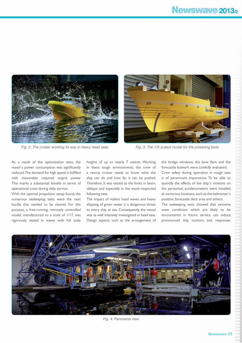
Fig. 4: Panorama view
Fig. 2: The cruiser working its way in heavy head seas Fig. 3: The 1/6 scaled model for the powering tests

Newswave 18
However, when called to duty, the DGzRS cruisers need to withstand the most severe sea states that can be expected in the North and Baltic Sea areas. Given its relatively small size compared to the sheer dimensions of the surrounding waves, the test series proved that the new cruiser design is quite robust and able to remain operational even in largest sea states. The superstructure geometry and arrangement were determined to be very effective in terms of protecting the vessel from heavy head sea impacts.As a conclusion, it can be stated that the hull form is a satisfying trade-off between open water performance and the behaviour in waves. Currently, the results and fi ndings of the test series at HSVA are incorporated into the fi nal ship concept by Fassmer and the DGzRS. With the detail design phase to start soon, the project is on track for delivery of the fi rst unit in 2015.
The DGzRS was founded in 1865. Since then she has carried out search and rescue missions as a charity – independently and accepting sole responsibility, fi nanced by its own funds and on a voluntary basis.
In fact, the DGzRS assumed a more or less public duty without claiming one cent of the public funding that is normally awarded to non-profi t organizations.
Approximately 300,000 sustaining members keep the rescue crews afl oat through regular contributions.
The German Maritime Search and Rescue Service (DGzRS)
180 full-time employees and round about 800 volunteers are on call on 20 rescue cruisers and 40 rescue boats – in more than 2,000 rescue missions each year, in all weathers, around the clock.
54 stations in the North Sea and Baltic Sea form a dense rescue network. All missions are coordinated by the central Maritime Rescue Co-ordination Centre in Bremen.
www.seenotretter.de
A New Towing Arrangement for Measurement of Wave Added Resistance in Oblique Seas
by Petri Valanto
In the framework of the research project PerSee (Performance in Seaway) the HSVA has carried out a large number of measurements on wave added resistance in regular waves in seven wave directions between 180° and 0° of ship heading. For this it was necessery to develop a new towing arrangement allowing the ship model motions in oblique seas as free as possible, but making it simultaneously possible to measure the towing resistance:The ship model is towed with a vertical
towing pole located in the middle of the ship. A vertical guiding pole at the bow controls the ship model direction. This guiding pole is fi xed onto a separate carriage moving freely in the x-direction. Both poles can freely move in the vertical direction. For accurate measurement of the towing force and the side force, each pole is connected to the model with a purpose-built force balance.The ship motion components roll, pitch and heave are completely free. The surge, sway, and yaw components are restrained with suitably soft springs allowing the cyclic
motions of the model in seaway, but keeping it softly on its course and position. In order to be able to adjust the restoring springs of the motion components completely separately, an additional carriage was constructed for the towing system to also separate the restoring springs for yaw and sway motions.The towing system is contructed so that all motion components, e.g. roll, can be individually fully restrained for research purposes. With this possibility we have already demonstrated the dramatic effect of parametric rolling in head seas on the ship resistance.

Newswave 19
For accurate measurement of wave added resistance the ship must be able to execute roll motions freely in all wave directions. In head and following seas parametric rolling, and in all other directions the wave excitation lead to ship roll motions. For this it is necessary to have the roll axis of the ship model in the correct height above the baseline, also when the ship model is connected to the towing system. In principle the same applies also to the pitch motion. However, in order not to cause an artifi cial and unreal trim moment on the model, the model should be towed in a feasible manner approximately at the height of the thrust bearing of the propeller shaft of the ship. This second alternative, which implies that the pitch axis is located
at the height of the thrust bearing, was priorisized in the tests for the mentioned PerSee Project. In order to facilitate these requirements the HSVA has constructed two purpose-built force balances measuring the towing and side forces in the ship fi xed coordinates and allowing the roll and pitch axes to be separated and the vertical distance between them to be adjusted. The new towing arrangement was used in the measurement of the ship (wave added) resistance in seaways with success. Propulsion tests using the same arrangement will follow in the coming winter to study the effi ciency of propulsion in realistic seaways. The new piece of equipment allows to carry out measurements on the resistance
of different ship bow forms also in oblique seas, thus giving impulses on ship hull design and optimisation. This is important as the highest resistance values are often not encountered in head seas, but in bow quartering seas, specially in the range of the frequently encountered relatively short waves. Second, it allows to study the effi ciency of the propulsion in seaway. We are convinced that the new towing arrangement will help in designing ship hulls for optimum performance in seaway and in choosing the best propulsion point for a chosen ship design.
Fig. 1: Trial version of the new towing arrangement for oblique seas in the HSVA large towing tank. The arrows show the direction of the movement of the different components of the system.

Hamburg Ship Model Basin • Bramfelder Straße 164 • D-22305 Hamburg
Phone: +49-40-692030 • Fax: +49-40-69203345 • Email: [email protected] • Web: www.hsva.de
ww
w.e
nvi
se.c
om
Member of Staff
Dr. Yongpyo Hong joined HSVA in March 2010 as a project manager in the Seakeeping, Manoeuvring & Offshore department. His main role in this position is to perform model tests and numerical analyses on the dynamic behaviour of various ships and offshore structures. He fi nished his MSc degree at Seoul National University in 2000, and got his PhD degree with the thesis on the dynamics of long fl exible marine risers at RIAM (Research Institute for Applied Mechanics) in Kyushu University (Japan) in 2004.Before joining HSVA, he worked as a senior research engineer for 6 years in Samsung
Heavy Industries, and was involved in many actual projects for offshore platforms and special vessels. His major activities included coupled dynamics of fl oating structures with moorings and risers, DP control of special vessels or drillships, investigation on springing and whipping phenomena of a ship in waves and engineering design of FPSO and DDS (deep-draft semi-submersible).Yongpyo likes to make walks outside with his wife and two sons into small pretty parks nearby the house. In his spare times, he enjoys reading books, listening to music, playing table tennis, and recently he tries to recover the old forgotten skill of playing piano.
Vistit us at MARINTEC CHINA, International Maritime Conference & Exhibition, 3rd–6th December 2013, Shanghai, China. You can fi nd us in the German Pavilion, hall no. N2 at our stand no. N2F21-04.
MARINTEC CHINA 2013
TITANIC II Model Test Held at HSVA
by Uwe Hollenbach
The Finnish Design Company Deltamarin and the Shipping Company Blue Star Line conducted the fi rst model testing of the proposed Titanic II at HSVA in September this year. Present day cruise liners have a completely different hull shape and therefore are unsuitable as references for the Titanic II project. The designer and the ship owner decided performing model tests is the only accurate and reliable method predicting the speed power characteristics for such a passenger vessel prototype as Titanic II.The Titanic II model was given the HSVA model number 5000. In honour of Titanic II and Blue Star Line, HSVA held a naming ceremony before the tests. World Project Director of Titanic II, Baljeet Singh, expressed her hopes and wishes for this project in her speech:
“It is a great honour to be invited here today to say a few words at this ceremony of the 5,000th
model for HSVA in its 100th year of operation. On behalf of the chairman and board of Blue Star Line, I would like to congratulate HSVA on reaching this milestone and wish you another 5,000 and more model tests. Today also marks the fi rst ever model test for the Titanic II. I have come many thousands of miles to be here with you all, inspired by the commitment of so many who have crossed the sea to make America their home. Titanic II is for all of them. It’s for the artists, the craftsman, the crew and the men, women and children who sailed on Titanic from Europe to America, their hopes, dreams, their courage and their aspirations. So, when the day comes, and it most surely will, when Titanic II sails into New York, you will be able to say that you were here, when it all began.”
Grete Ernst, Project Manager, Resi-stance & Propulsion, HSVA, christens
the Titanic II model at the naming cere-mony at the HSVA facility in Hamburg. Behind Mrs Ernst are (l-r) Uwe Hollen-bach, Director, Head of Resistance & Propulsion; Jürgen Friesch, Managing Director; Baljeet Singh, World Project Director of Titanic II; Markku Kanerva,
Director Sales, Deltamarin.


![Applied Ocean Research · 2021. 3. 26. · PPTC Propeller. at full scale than model scale [5,6]. ESD investigation, optimisation and Table analyses should therefore be performed at](https://img.pdfslide.us/doc/110x75/61281080602a381eee3935f4/applied-ocean-research-2021-3-26-pptc-propeller-at-full-scale-than-model-scale.jpg)