Embed Size (px)
Citation preview
iIntegrity, Ingenuity, Innovation
WE BUILD THE BEST CABLE BUSPERIOD.
superiortray.com Integrity, Ingenuity, Innovation
iiIntegrity, Ingenuity, Innovation
Introduction to 2Standard System Features 4Ownership Benefits 6Custom Design & Fabrication 8Custom Layout Solutions 10Corrosive Environments 11Cable Bus Components 12System Balance & Optimization 14Technical Information 16Ampacity Comparison 18
Sizing 18Trenched Systems 22Integrated Walkway 24High Bus 26Clients 28
Rev. 2016-08-31

Super iorTray.com | 6 0 4 . 5 7 2 . 4 41 91
Superior Tray is a major manufacturer in the cable bus and cable tray industries. Superior Tray is a Canadian owned and operated company.
Located in Surrey, British Columbia, Superior Tray was established in 1996 as a custom metal fabrication shop. Superior Tray expanded into cable management and power distribution systems in 2004, and has since redesigned the manufacturing of cable bus and cable tray, expanding and developing product lines for the 21st century. Superior Tray continues to design and develop new electrical distribution and cable management systems while still offering exceptional craftsmanship. Our agents and dealers form a complete distribution network to serve our valued customers in Canada, the United States, Australia, and Central America. Each agent is a trained specialist in our product line, and is backed up by an expert technical team of designers and engineers at our head office. The entire Superior Tray team works hard to support our customers by providing answers to our customer’s questions quickly and directly. No job is too big for our distribution network to handle. Combined with the shortest lead times in the industry and competitive pricing, Superior Tray takes pride in supplying products that are done right, on budget, and on time.
You can be assured Superior Tray will exceed your expectations with our state-of-the-art facility equipped with CNC machinery, automated production lines, robotics, and highly trained technical staff. We can take a blueprint, CAD model, sketch, or even a simple thought to turn your concept into the perfect solution. Superior Tray will work with you every step of the way to ensure your complete satisfaction. Our product line is not limited to one facet; we are constantly developing and expanding concepts to push the envelope of design. Some examples of this include our Integrated Walkway and Service Chase Way systems. These integrated systems incorporate cable bus or steam, water, gas or any other process lines into a walkway or chase way. Doing so dramatically reduces the footprint and the cost as compared to separate installations. Products manufactured by Superior Tray are fabricated to the highest level of standards. We have received numerous CSA and UL certifications for our products. CSA (Canadian Standards Association) and UL (Underwriters Laboratories) are third party independent product safety testing organizations, which perform thorough testing of any product we produce before issuing a certification. Product certifications and standards information from CSA and UL can be found at www.csa.ca, and www.ul.com, respectively.
2Integrity, Ingenuity, Innovation
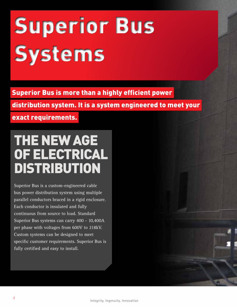
Superior Bus Systems
Superior Bus is more than a highly efficient power
distribution system. It is a system engineered to meet your
exact requirements.
THE NEW AGE OF ELECTRICAL DISTRIBUTION Superior Bus is a custom-engineered cable
bus power distribution system using multiple
parallel conductors braced in a rigid enclosure.
Each conductor is insulated and fully
continuous from source to load. Standard
Superior Bus systems can carry 400 - 10,400A
per phase with voltages from 600V to 218kV.
Custom systems can be designed to meet
specific customer requirements. Superior Bus is
fully certified and easy to install.
Super iorTray.com | 6 0 4 . 5 7 2 . 4 41 93
4Integrity, Ingenuity, Innovation
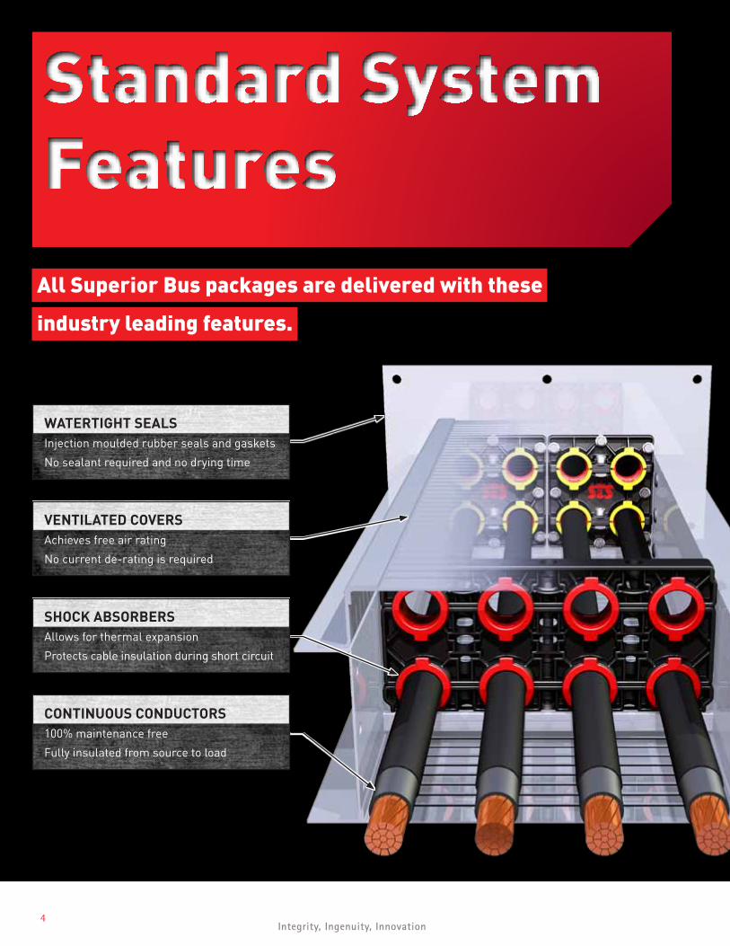
Standard SystemFeatures
WATERTIGHT SEALSInjection moulded rubber seals and gaskets
No sealant required and no drying time
VENTILATED COVERSAchieves free air rating
No current de-rating is required
SHOCK ABSORBERSAllows for thermal expansion
Protects cable insulation during short circuit
CONTINUOUS CONDUCTORS100% maintenance free
Fully insulated from source to load
All Superior Bus packages are delivered with these
industry leading features.
Super iorTray.com | 6 0 4 . 5 7 2 . 4 41 95
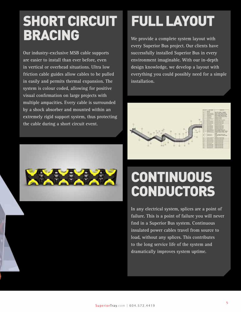
SHORT CIRCUIT BRACINGOur industry-exclusive MSB cable supports
are easier to install than ever before, even
in vertical or overhead situations. Ultra low
friction cable guides allow cables to be pulled
in easily and permits thermal expansion. The
system is colour coded, allowing for positive
visual confirmation on large projects with
multiple ampacities. Every cable is surrounded
by a shock absorber and mounted within an
extremely rigid support system, thus protecting
the cable during a short circuit event.
CONTINUOUS CONDUCTORSIn any electrical system, splices are a point of
failure. This is a point of failure you will never
find in a Superior Bus system. Continuous
insulated power cables travel from source to
load, without any splices. This contributes
to the long service life of the system and
dramatically improves system uptime.
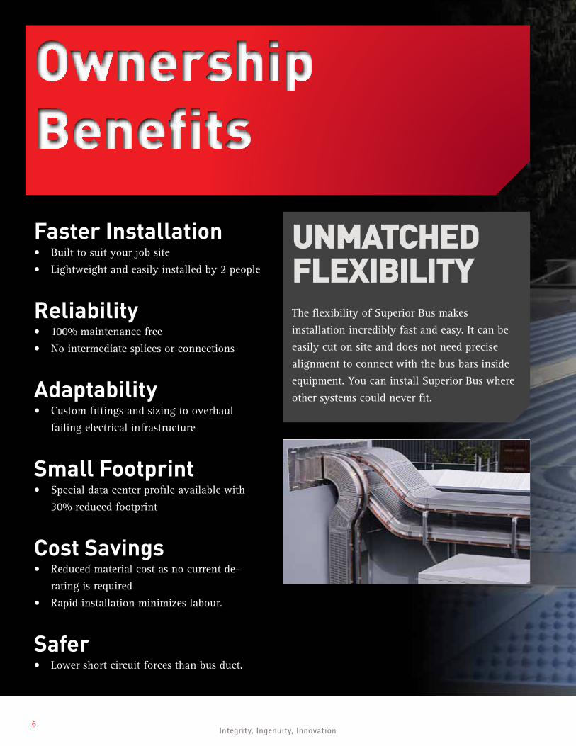
FULL LAYOUTWe provide a complete system layout with
every Superior Bus project. Our clients have
successfully installed Superior Bus in every
environment imaginable. With our in-depth
design knowledge, we develop a layout with
everything you could possibly need for a simple
installation.
6Integrity, Ingenuity, Innovation
Ownership Benefits
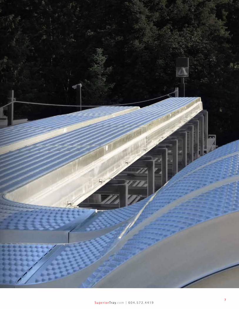
UNMATCHED FLEXIBILITYThe flexibility of Superior Bus makes
installation incredibly fast and easy. It can be
easily cut on site and does not need precise
alignment to connect with the bus bars inside
equipment. You can install Superior Bus where
other systems could never fit.
Faster Installation• Built to suit your job site
• Lightweight and easily installed by 2 people
Reliability• 100% maintenance free
• No intermediate splices or connections
Adaptability• Custom fittings and sizing to overhaul
failing electrical infrastructure
Small Footprint• Special data center profile available with
30% reduced footprint
Cost Savings• Reduced material cost as no current de-
rating is required
• Rapid installation minimizes labour.
Safer• Lower short circuit forces than bus duct.
Super iorTray.com | 6 0 4 . 5 7 2 . 4 41 97
8Integrity, Ingenuity, Innovation
Custom Design & Fabrication
Our experienced team can design a Superior Bus system
that suits your specific needs.
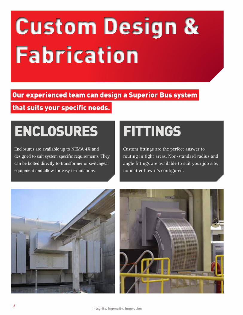
ENCLOSURESEnclosures are available up to NEMA 4X and
designed to suit system specific requirements. They
can be bolted directly to transformer or switchgear
equipment and allow for easy terminations.
FITTINGSCustom fittings are the perfect answer to
routing in tight areas. Non-standard radius and
angle fittings are available to suit your job site,
no matter how it’s configured.
Super iorTray.com | 6 0 4 . 5 7 2 . 4 41 99
FROST HEAVECertain soil conditions exist where underground
ice can form and cause the ground to heave.
Hinged fittings are available to accommodate
the potentially damaging effect of frost heave.
ISOLATIONSections of Superior Bus can be fabricated from
UV resistant UHMW polyethylene. This is done
to electrically isolate a section of cable bus
enclosure from the remainder of the system.
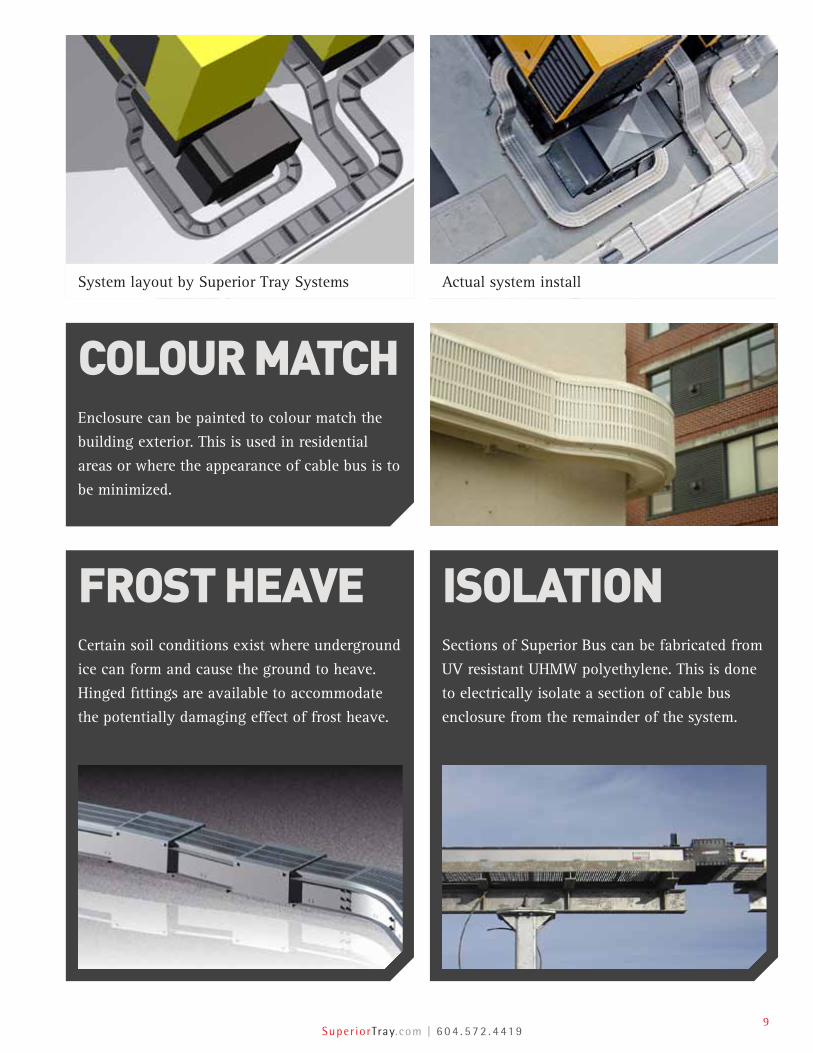
COLOUR MATCHEnclosure can be painted to colour match the
building exterior. This is used in residential
areas or where the appearance of cable bus is to
be minimized.
System layout by Superior Tray Systems Actual system install
10Integrity, Ingenuity, Innovation
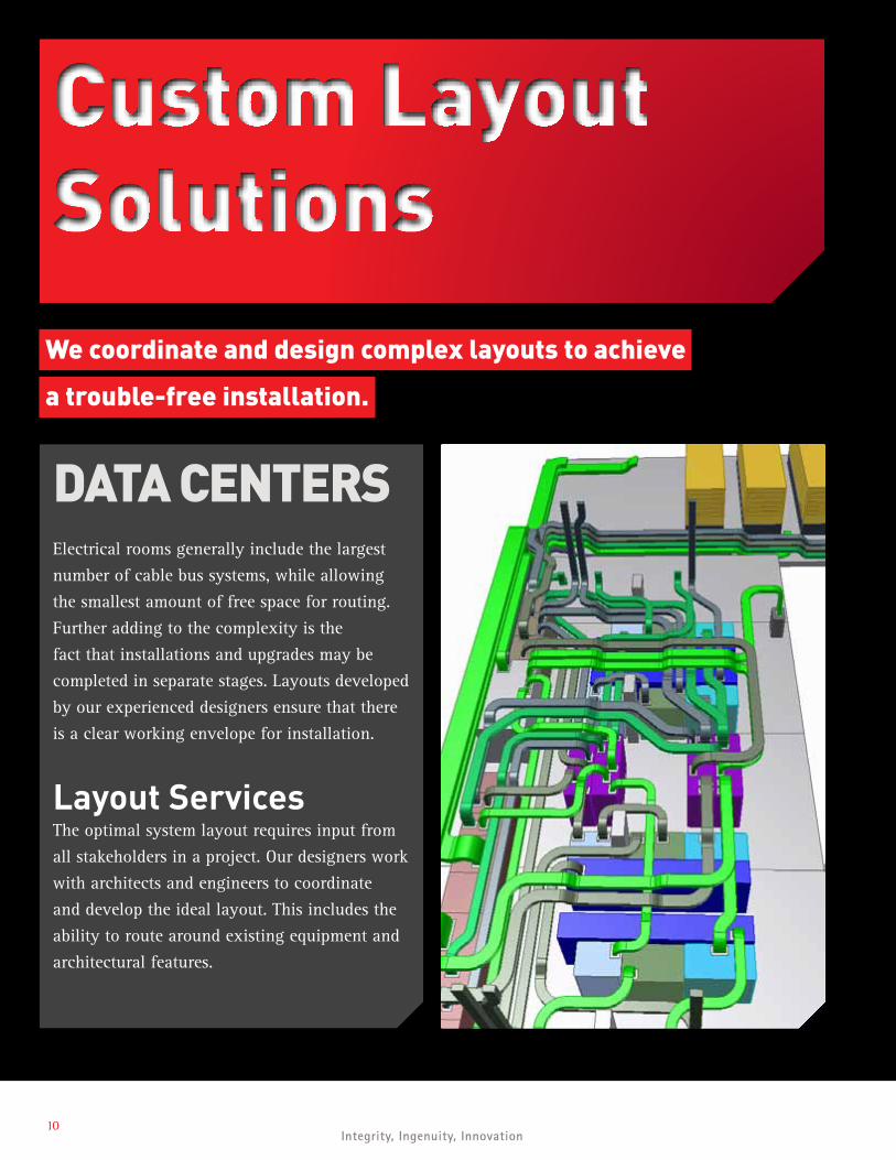
Custom Layout Solutions
We coordinate and design complex layouts to achieve
a trouble-free installation.
DATA CENTERSElectrical rooms generally include the largest
number of cable bus systems, while allowing
the smallest amount of free space for routing.
Further adding to the complexity is the
fact that installations and upgrades may be
completed in separate stages. Layouts developed
by our experienced designers ensure that there
is a clear working envelope for installation.
Layout ServicesThe optimal system layout requires input from
all stakeholders in a project. Our designers work
with architects and engineers to coordinate
and develop the ideal layout. This includes the
ability to route around existing equipment and
architectural features.
Super iorTray.com | 6 0 4 . 5 7 2 . 4 41 911
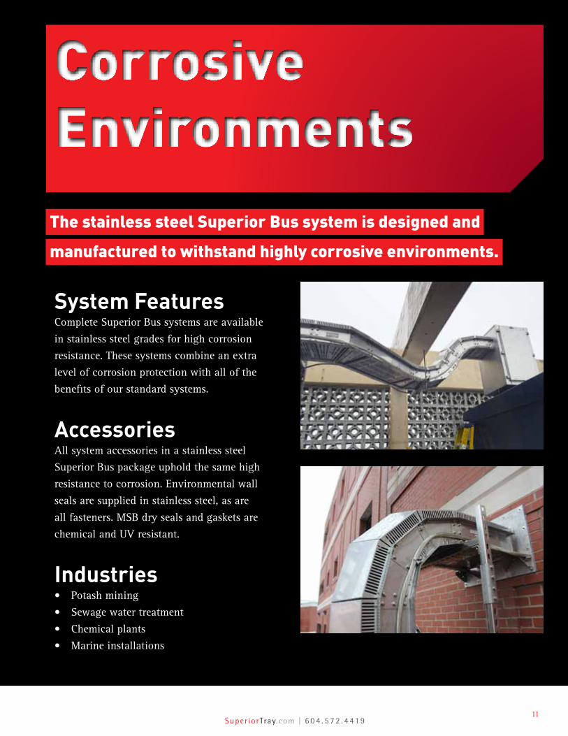
Corrosive Environments
The stainless steel Superior Bus system is designed and
manufactured to withstand highly corrosive environments.
System FeaturesComplete Superior Bus systems are available
in stainless steel grades for high corrosion
resistance. These systems combine an extra
level of corrosion protection with all of the
benefits of our standard systems.
AccessoriesAll system accessories in a stainless steel
Superior Bus package uphold the same high
resistance to corrosion. Environmental wall
seals are supplied in stainless steel, as are
all fasteners. MSB dry seals and gaskets are
chemical and UV resistant.
Industries• Potash mining
• Sewage water treatment
• Chemical plants
• Marine installations
12Integrity, Ingenuity, Innovation
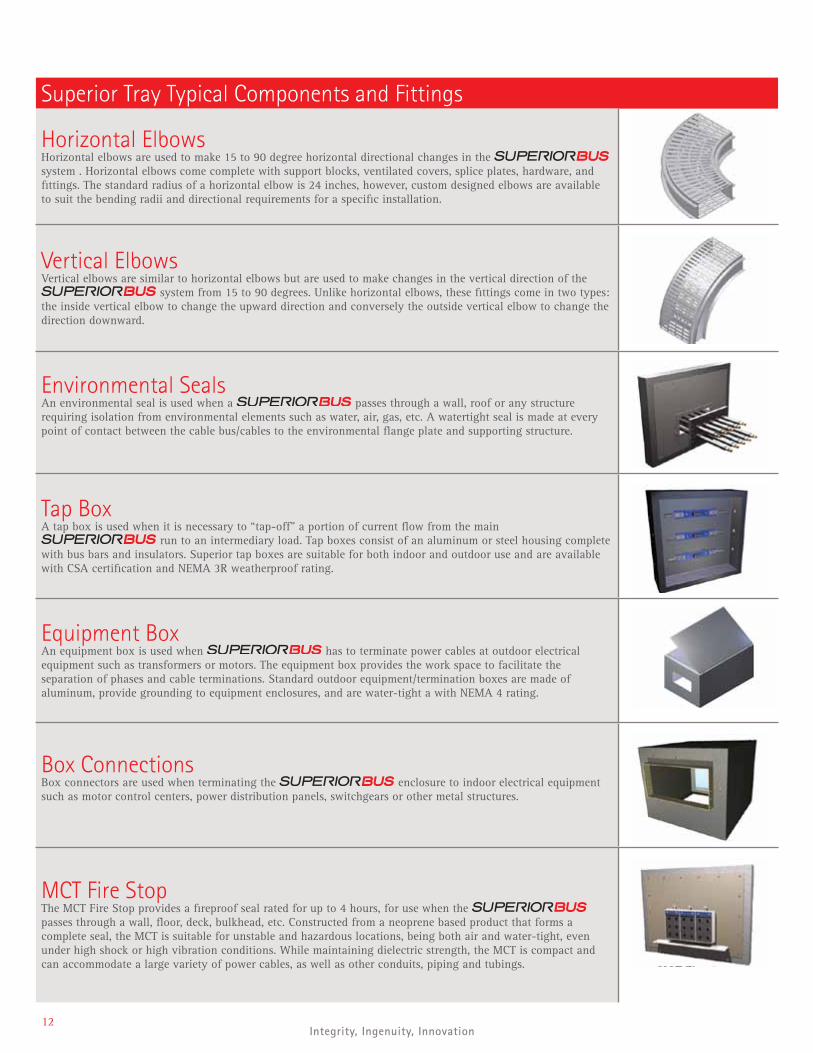
Superior Tray Typical Components and Fittings
Horizontal ElbowsHorizontal elbows are used to make 15 to 90 degree horizontal directional changes in the system . Horizontal elbows come complete with support blocks, ventilated covers, splice plates, hardware, and fittings. The standard radius of a horizontal elbow is 24 inches, however, custom designed elbows are available to suit the bending radii and directional requirements for a specific installation.
Vertical ElbowsVertical elbows are similar to horizontal elbows but are used to make changes in the vertical direction of the
system from 15 to 90 degrees. Unlike horizontal elbows, these fittings come in two types: the inside vertical elbow to change the upward direction and conversely the outside vertical elbow to change the direction downward.
Environmental SealsAn environmental seal is used when a passes through a wall, roof or any structure requiring isolation from environmental elements such as water, air, gas, etc. A watertight seal is made at every point of contact between the cable bus/cables to the environmental flange plate and supporting structure.
Tap BoxA tap box is used when it is necessary to “tap-off” a portion of current flow from the main
run to an intermediary load. Tap boxes consist of an aluminum or steel housing complete with bus bars and insulators. Superior tap boxes are suitable for both indoor and outdoor use and are available with CSA certification and NEMA 3R weatherproof rating.
Equipment Box An equipment box is used when has to terminate power cables at outdoor electrical equipment such as transformers or motors. The equipment box provides the work space to facilitate the separation of phases and cable terminations. Standard outdoor equipment/termination boxes are made of aluminum, provide grounding to equipment enclosures, and are water-tight a with NEMA 4 rating.
Box ConnectionsBox connectors are used when terminating the enclosure to indoor electrical equipment such as motor control centers, power distribution panels, switchgears or other metal structures.
MCT Fire StopThe MCT Fire Stop provides a fireproof seal rated for up to 4 hours, for use when the passes through a wall, floor, deck, bulkhead, etc. Constructed from a neoprene based product that forms a complete seal, the MCT is suitable for unstable and hazardous locations, being both air and water-tight, even under high shock or high vibration conditions. While maintaining dielectric strength, the MCT is compact and can accommodate a large variety of power cables, as well as other conduits, piping and tubings.
Super iorTray.com | 6 0 4 . 5 7 2 . 4 41 913
Superior Tray Typical Components and Fittings
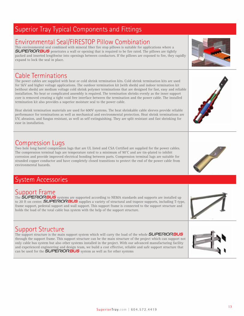
Environmental Seal/FIRESTOP Pillow CombinationThis environmental seal combined with mineral fiber fire stop pillows is suitable for applications where a
penetrates a wall or opening that is required to be fire rated. The pillows are tightly packed and inserted lengthwise into openings between conductors. If the pillows are exposed to fire, they rapidly expand to lock the seal in place.
Cable TerminationsThe power cables are supplied with heat or cold shrink termination kits. Cold shrink termination kits are used for 5kV and higher voltage applications. The outdoor termination kit (with sheds) and indoor termination kit (without sheds) are medium voltage cold shrink polymer terminations that are designed for fast, easy and reliable installation. No heat or complicated assembly is required. The termination shrinks evenly as the inner support core is removed creating a tight void free interface between the termination and the power cable. The installed termination kit also provides a superior moisture seal to the power cable.
Heat shrink termination materials are used for 600V systems. The heat shrinkable cable sleeves provide reliable performance for terminations as well as mechanical and environmental protection. Heat shrink terminations are UV, abrasion, and fungus resistant, as well as self extinguishing. They are split resistant and fast shrinking for ease in installation.
Compression LugsTwo hole long barrel compression lugs that are UL listed and CSA Certified are supplied for the power cables. The compression terminal lugs are temperature rated to a minimum of 90˚C and are tin-plated to inhibit corrosion and provide improved electrical bonding between parts. Compression terminal lugs are suitable for stranded copper conductor and have completely closed transitions to protect the end of the power cable from environmental hazards.
System Accessories
Support FrameThe systems are supported according to NEMA standards and supports are installed up to 20 ft on center. supplies a variety of structural and trapeze supports, including T-type, frame support, pedestal support and wall support. This support frame is connected to the support structure and holds the load of the total cable bus system with the help of the support structure.
Support StructureThe support structure is the main support system which will carry the load of the whole through the support frame. This support structure can be the main structure of the project which can support not only cable bus system but also other systems installed in the project. With our advanced manufacturing facility and experienced engineering and design team, we build a cost effective, reliable and safe support structure that can be used for the system as well as for other systems
14Integrity, Ingenuity, Innovation
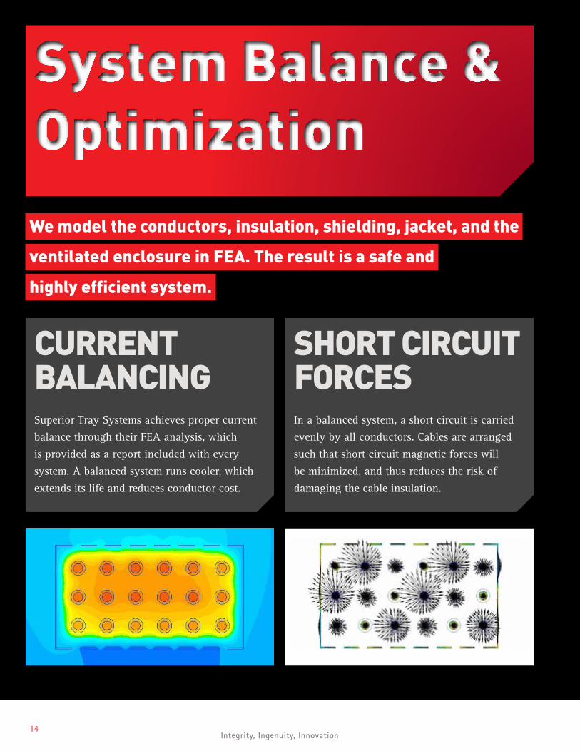
CURRENT BALANCINGSuperior Tray Systems achieves proper current
balance through their FEA analysis, which
is provided as a report included with every
system. A balanced system runs cooler, which
extends its life and reduces conductor cost.
System Balance & Optimization
We model the conductors, insulation, shielding, jacket, and the
ventilated enclosure in FEA. The result is a safe and
highly efficient system.
SHORT CIRCUIT FORCESIn a balanced system, a short circuit is carried
evenly by all conductors. Cables are arranged
such that short circuit magnetic forces will
be minimized, and thus reduces the risk of
damaging the cable insulation.
Super iorTray.com | 6 0 4 . 5 7 2 . 4 41 915
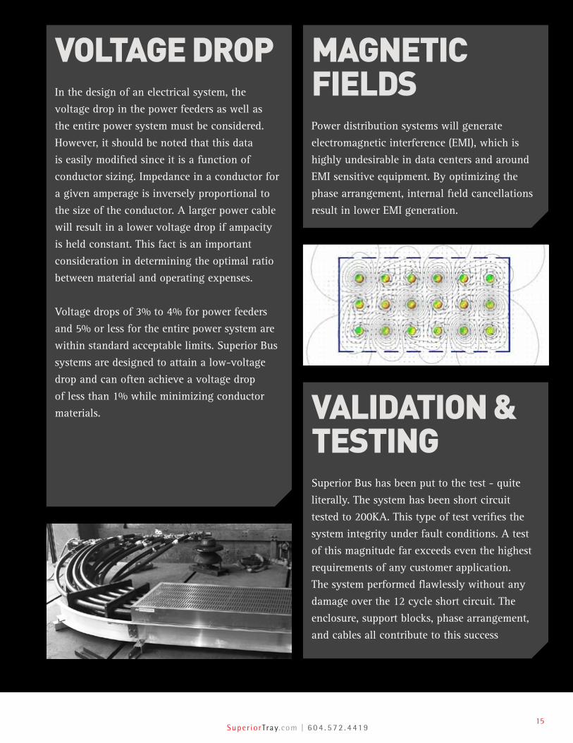
VALIDATION & TESTINGSuperior Bus has been put to the test - quite
literally. The system has been short circuit
tested to 200KA. This type of test verifies the
system integrity under fault conditions. A test
of this magnitude far exceeds even the highest
requirements of any customer application.
The system performed flawlessly without any
damage over the 12 cycle short circuit. The
enclosure, support blocks, phase arrangement,
and cables all contribute to this success
MAGNETIC FIELDSPower distribution systems will generate
electromagnetic interference (EMI), which is
highly undesirable in data centers and around
EMI sensitive equipment. By optimizing the
phase arrangement, internal field cancellations
result in lower EMI generation.
VOLTAGE DROPIn the design of an electrical system, the
voltage drop in the power feeders as well as
the entire power system must be considered.
However, it should be noted that this data
is easily modified since it is a function of
conductor sizing. Impedance in a conductor for
a given amperage is inversely proportional to
the size of the conductor. A larger power cable
will result in a lower voltage drop if ampacity
is held constant. This fact is an important
consideration in determining the optimal ratio
between material and operating expenses.
Voltage drops of 3% to 4% for power feeders
and 5% or less for the entire power system are
within standard acceptable limits. Superior Bus
systems are designed to attain a low-voltage
drop and can often achieve a voltage drop
of less than 1% while minimizing conductor
materials.
16Integrity, Ingenuity, Innovation
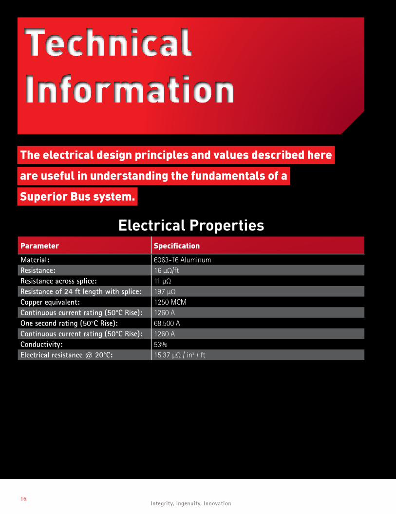
Technical Information
The electrical design principles and values described here
are useful in understanding the fundamentals of a
Superior Bus system.
Electrical PropertiesParameter Specification
Material: 6063-T6 AluminumResistance: 16 µΩ/ftResistance across splice: 11 µΩResistance of 24 ft length with splice: 197 µΩCopper equivalent: 1250 MCMContinuous current rating (50°C Rise): 1260 AOne second rating (50°C Rise): 68,500 AContinuous current rating (50°C Rise): 1260 AConductivity: 53%Electrical resistance @ 20°C: 15.37 µΩ / in2 / ft
Super iorTray.com | 6 0 4 . 5 7 2 . 4 41 917
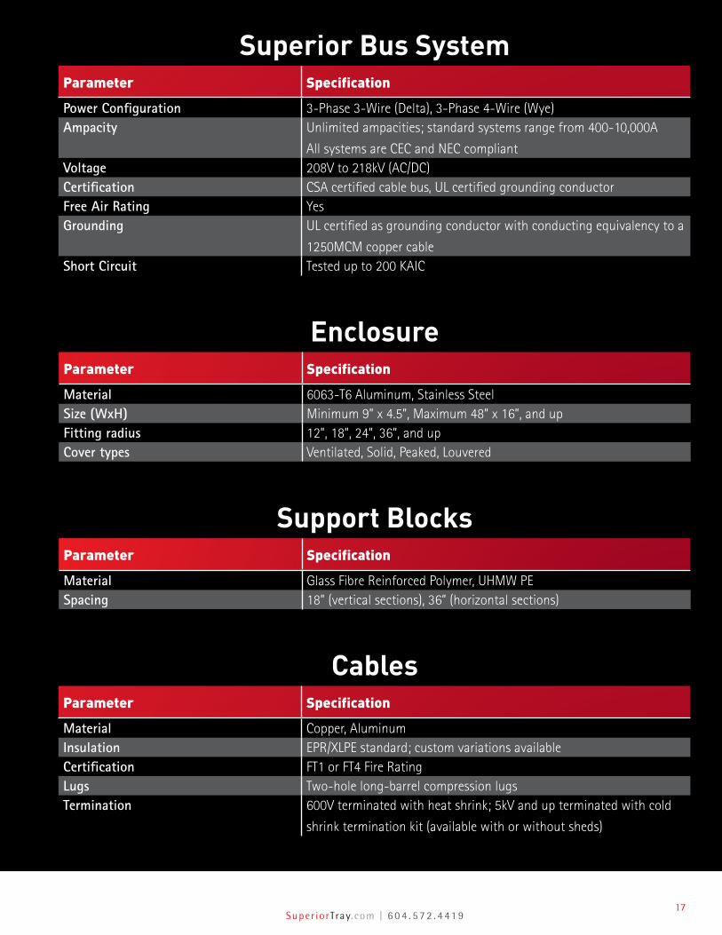
Superior Bus SystemParameter Specification
Power Configuration 3-Phase 3-Wire (Delta), 3-Phase 4-Wire (Wye)Ampacity Unlimited ampacities; standard systems range from 400-10,000A
All systems are CEC and NEC compliantVoltage 208V to 218kV (AC/DC)Certification CSA certified cable bus, UL certified grounding conductorFree Air Rating YesGrounding UL certified as grounding conductor with conducting equivalency to a
1250MCM copper cableShort Circuit Tested up to 200 KAIC
EnclosureParameter Specification
Material 6063-T6 Aluminum, Stainless SteelSize (WxH) Minimum 9” x 4.5”, Maximum 48” x 16”, and upFitting radius 12”, 18”, 24”, 36”, and upCover types Ventilated, Solid, Peaked, Louvered
Support BlocksParameter Specification
Material Glass Fibre Reinforced Polymer, UHMW PESpacing 18” (vertical sections), 36” (horizontal sections)
CablesParameter Specification
Material Copper, AluminumInsulation EPR/XLPE standard; custom variations availableCertification FT1 or FT4 Fire RatingLugs Two-hole long-barrel compression lugsTermination 600V terminated with heat shrink; 5kV and up terminated with cold
shrink termination kit (available with or without sheds)

18Integrity, Ingenuity, Innovation
SYSTEMCONDUCTOR SIZE
(MCM)
NEC AMPACITY (AMP)OF 90˚C RATED
CONDUCTOR AND 40˚C AMBIENT TEMPERATURE
CANADIAN SYSTEMS AMPACITY (AMP) OF 90˚C RATED
CONDUCTOR AND 30˚C AMBIENT TEMPERATURE
INTERLOCKED ARMORED CABLE
(IN TRAY)(AMP)
THREE SINGLE CONDUCTOR CABLES IN CONDUIT (IN AIR)
(AMP)
600V System500 637 660 405 477750 805 845 500 5981000 960 1000 585 689
5kV System500 695 730 425 473750 900 945 525 5791000 1075 1129 590 659
15kV System500 685 719 470 481750 885 929 570 5881000 1060 1113 650 677
Superior Cable Bus Sizing- Ampacity Listing1. The reference figures shown are the typical arrangement of power cables in a multi-layered System. 2. Each system is designed to ensure reliable performance and the client’s unique requirements.3. We custom build System with different dimensions for clients where there are space restrictions at the project sites.4. For higher cable bus voltage (35kV, 69kV, and up) contact Superior Tray at [email protected] or +1-604-572-4419.5. Ampacity ratings are given based on a 90°C operating temperature.
TABLE A - 600 VOLTS 3-PHASE, 3-WIRE SYSTEM (AMPACITY AT 40˚C AMBIENT FOR NEC EXCEPT THOSE MARKED * WHICH IS AT 30˚C AMBIENT FOR CEC)
AMPACITY (AMPS) VOLTAGE (V)SYSTEM
CONFIGURATIONENCLOSURE DIMENSIONS (IN INCHES)
FIGURE REFERENCEA B C
800 600 3-Phase, 3-Wire 12 1/2 6 9 Type 1
1200 600 3-Phase, 3-Wire 12 1/2 6 9 Type 2
1300 600 3-Phase, 3-Wire 12 1/2 6 9 Type 2
1400 600 3-Phase, 3-Wire 12 1/2 8 9 Type 2
1600 600 3-Phase, 3-Wire 12 1/2 8 9 Type 2
1750 600 3-Phase, 3-Wire 12 1/2 8 9 Type 2
1950 600 3-Phase, 3-Wire 15 1/2 6 12 Type 3
2100 600 3-Phase, 3-Wire 21 1/2 8 18 Type 3
2600 600 3-Phase, 3-Wire 21 1/2 6 18 Type 3A
2800 600 3-Phase, 3-Wire 21 1/2 8 18 Type 3A
3100 600 3-Phase, 3-Wire 21 1/2 8 18 Type 3A
3300 600 3-Phase, 3-Wire 21 1/2 8 18 Type 3A
3500 600 3-Phase, 3-Wire 21 1/2 8 18 Type 3A
3900 600 3-Phase, 3-Wire 21 1/2 10 18 Type 4
4200 600 3-Phase, 3-Wire 21 1/2 10 18 Type 4
4700 600 3-Phase, 3-Wire 21 1/2 10 18 Type 4
5000 600 3-Phase, 3-Wire 21 1/2 10 18 Type 4
5300 600 3-Phase, 3-Wire 21 1/2 10 18 Type 4
5300-11000 600
Custom designed and built, please contact Superior Tray for more information.Heavy Duty System of Up To 20,000 600
Ampacity ComparisonsBased on the NEC & ICEA Tables at 90°C in 40°C Ambient, the following table illustrates the greater current carrying capacity of
as compared to other methods:
A
Super iorTray.com | 6 0 4 . 5 7 2 . 4 41 919
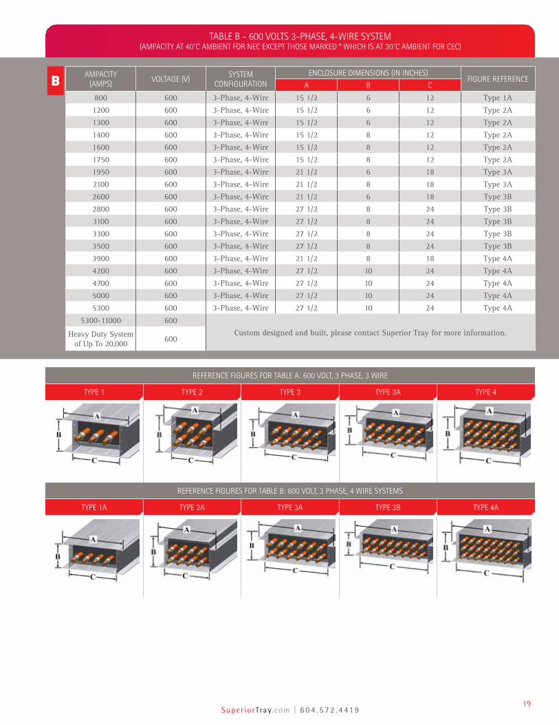
REFERENCE FIGURES FOR TABLE A: 600 VOLT, 3 PHASE, 3 WIRE
TYPE 1 TYPE 2 TYPE 3 TYPE 3A TYPE 4
REFERENCE FIGURES FOR TABLE B: 600 VOLT, 3 PHASE, 4 WIRE SYSTEMS
TYPE 1A TYPE 2A TYPE 3A TYPE 3B TYPE 4A
TABLE B - 600 VOLTS 3-PHASE, 4-WIRE SYSTEM (AMPACITY AT 40˚C AMBIENT FOR NEC EXCEPT THOSE MARKED * WHICH IS AT 30˚C AMBIENT FOR CEC)
AMPACITY (AMPS)
VOLTAGE (V)SYSTEM
CONFIGURATIONENCLOSURE DIMENSIONS (IN INCHES)
FIGURE REFERENCEA B C
800 600 3-Phase, 4-Wire 15 1/2 6 12 Type 1A
1200 600 3-Phase, 4-Wire 15 1/2 6 12 Type 2A
1300 600 3-Phase, 4-Wire 15 1/2 6 12 Type 2A
1400 600 3-Phase, 4-Wire 15 1/2 8 12 Type 2A
1600 600 3-Phase, 4-Wire 15 1/2 8 12 Type 2A
1750 600 3-Phase, 4-Wire 15 1/2 8 12 Type 2A
1950 600 3-Phase, 4-Wire 21 1/2 6 18 Type 3A
2100 600 3-Phase, 4-Wire 21 1/2 8 18 Type 3A
2600 600 3-Phase, 4-Wire 21 1/2 6 18 Type 3B
2800 600 3-Phase, 4-Wire 27 1/2 8 24 Type 3B
3100 600 3-Phase, 4-Wire 27 1/2 8 24 Type 3B
3300 600 3-Phase, 4-Wire 27 1/2 8 24 Type 3B
3500 600 3-Phase, 4-Wire 27 1/2 8 24 Type 3B
3900 600 3-Phase, 4-Wire 21 1/2 8 18 Type 4A
4200 600 3-Phase, 4-Wire 27 1/2 10 24 Type 4A
4700 600 3-Phase, 4-Wire 27 1/2 10 24 Type 4A
5000 600 3-Phase, 4-Wire 27 1/2 10 24 Type 4A
5300 600 3-Phase, 4-Wire 27 1/2 10 24 Type 4A
5300-11000 600
Custom designed and built, please contact Superior Tray for more information.Heavy Duty System of Up To 20,000 600
B

20Integrity, Ingenuity, Innovation
TYPE 2 TYPE 3 TYPE 3A TYPE 4
TABLE C - 5kV 3-PHASE, 3-WIRE SYSTEM (AMPACITY AT 40˚C AMBIENT)
AMPACITY (AMPS) VOLTAGE (kV)SYSTEM
CONFIGURATIONENCLOSURE DIMENSIONS (IN INCHES)
FIGURE REFERENCEA B C
1100 5 3-Phase, 3-Wire 12 1/2 6 9 Type 2
1300 5 3-Phase, 3-Wire 12 1/2 8 9 Type 2
1800 5 3-Phase, 3-Wire 12 1/2 8 9 Type 2
2000 5 3-Phase, 3-Wire 21 1/2 8 18 Type 3
2200 5 3-Phase, 3-Wire 21 1/2 6 18 Type 3A
2700 5 3-Phase, 3-Wire 21 1/2 8 18 Type 3
3600 5 3-Phase, 3-Wire 21 1/2 8 18 Type 3A
4100 5 3-Phase, 3-Wire 21 1/2 10 18 Type 4
5400 5 3-Phase, 3-Wire 21 1/2 10 28 Type 4
Above 5400 5 Custom designed and built, please contact Superior Tray for more information.
TABLE D - 5kV 3-PHASE, 4-WIRE SYSTEM (AMPACITY AT 40˚C AMBIENT)
AMPACITY (AMPS) VOLTAGE (kV)SYSTEM
CONFIGURATIONENCLOSURE DIMENSIONS (IN INCHES)
FIGURE REFERENCEA B C
1100 5 3-Phase, 4-Wire 15 1/2 6 12 Type 2A
1300 5 3-Phase, 4-Wire 15 1/2 8 12 Type 2A
1800 5 3-Phase, 4-Wire 15 1/2 8 12 Type 2A
2000 5 3-Phase, 4-Wire 21 1/2 8 18 Type 3A
2200 5 3-Phase, 4-Wire 21 1/2 6 24 Type 3B
2700 5 3-Phase, 4-Wire 21 1/2 8 18 Type 3A
3600 5 3-Phase, 4-Wire 21 1/2 10 18 Type 4
4100 5 3-Phase, 4-Wire 27 1/2 10 24 Type 4A
5400 5 3-Phase, 4-Wire 33 1/2 10 24 Type 4A
Above 5400 5 Custom designed and built, please contact Superior Tray for more information.
TYPE 2A TYPE 3A TYPE 3B TYPE 4 TYPE 4A
C
D
Super iorTray.com | 6 0 4 . 5 7 2 . 4 41 921
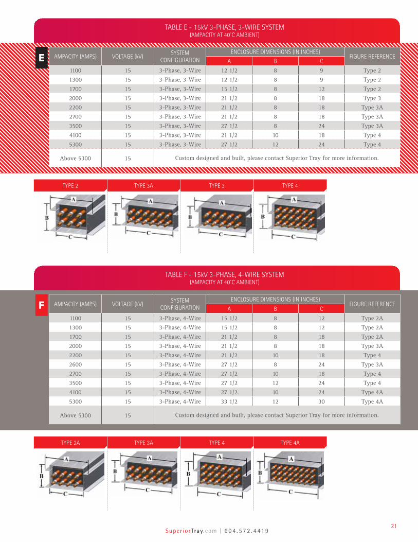
TABLE E - 15kV 3-PHASE, 3-WIRE SYSTEM (AMPACITY AT 40˚C AMBIENT)
AMPACITY (AMPS) VOLTAGE (kV)SYSTEM
CONFIGURATIONENCLOSURE DIMENSIONS (IN INCHES)
FIGURE REFERENCEA B C
1100 15 3-Phase, 3-Wire 12 1/2 8 9 Type 2
1300 15 3-Phase, 3-Wire 12 1/2 8 9 Type 2
1700 15 3-Phase, 3-Wire 15 1/2 8 12 Type 2
2000 15 3-Phase, 3-Wire 21 1/2 8 18 Type 3
2200 15 3-Phase, 3-Wire 21 1/2 8 18 Type 3A
2700 15 3-Phase, 3-Wire 21 1/2 8 18 Type 3A
3500 15 3-Phase, 3-Wire 27 1/2 8 24 Type 3A
4100 15 3-Phase, 3-Wire 21 1/2 10 18 Type 4
5300 15 3-Phase, 3-Wire 27 1/2 12 24 Type 4
Above 5300 15 Custom designed and built, please contact Superior Tray for more information.
TABLE F - 15kV 3-PHASE, 4-WIRE SYSTEM (AMPACITY AT 40˚C AMBIENT)
AMPACITY (AMPS) VOLTAGE (kV)SYSTEM
CONFIGURATIONENCLOSURE DIMENSIONS (IN INCHES)
FIGURE REFERENCEA B C
1100 15 3-Phase, 4-Wire 15 1/2 8 12 Type 2A
1300 15 3-Phase, 4-Wire 15 1/2 8 12 Type 2A
1700 15 3-Phase, 4-Wire 21 1/2 8 18 Type 2A
2000 15 3-Phase, 4-Wire 21 1/2 8 18 Type 3A
2200 15 3-Phase, 4-Wire 21 1/2 10 18 Type 4
2600 15 3-Phase, 4-Wire 27 1/2 8 24 Type 3A
2700 15 3-Phase, 4-Wire 27 1/2 10 18 Type 4
3500 15 3-Phase, 4-Wire 27 1/2 12 24 Type 4
4100 15 3-Phase, 4-Wire 27 1/2 10 24 Type 4A
5300 15 3-Phase, 4-Wire 33 1/2 12 30 Type 4A
Above 5300 15 Custom designed and built, please contact Superior Tray for more information.
TYPE 2 TYPE 3A TYPE 3 TYPE 4
TYPE 2A TYPE 3A TYPE 4 TYPE 4A
E
F
22Integrity, Ingenuity, Innovation
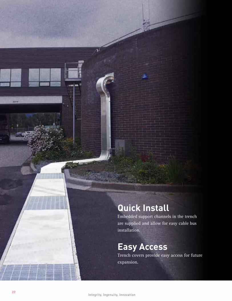
Quick InstallEmbedded support channels in the trench
are supplied and allow for easy cable bus
installation.
Easy AccessTrench covers provide easy access for future
expansion.
Super iorTray.com | 6 0 4 . 5 7 2 . 4 41 923
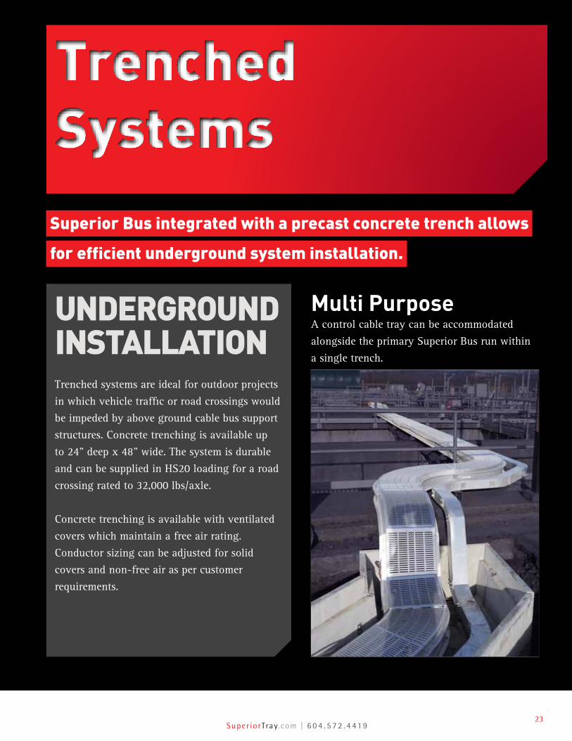
TrenchedSystems
Superior Bus integrated with a precast concrete trench allows
for efficient underground system installation.
UNDERGROUNDINSTALLATION Trenched systems are ideal for outdoor projects
in which vehicle traffic or road crossings would
be impeded by above ground cable bus support
structures. Concrete trenching is available up
to 24” deep x 48” wide. The system is durable
and can be supplied in HS20 loading for a road
crossing rated to 32,000 lbs/axle.
Concrete trenching is available with ventilated
covers which maintain a free air rating.
Conductor sizing can be adjusted for solid
covers and non-free air as per customer
requirements.
Multi PurposeA control cable tray can be accommodated
alongside the primary Superior Bus run within
a single trench.
24Integrity, Ingenuity, Innovation
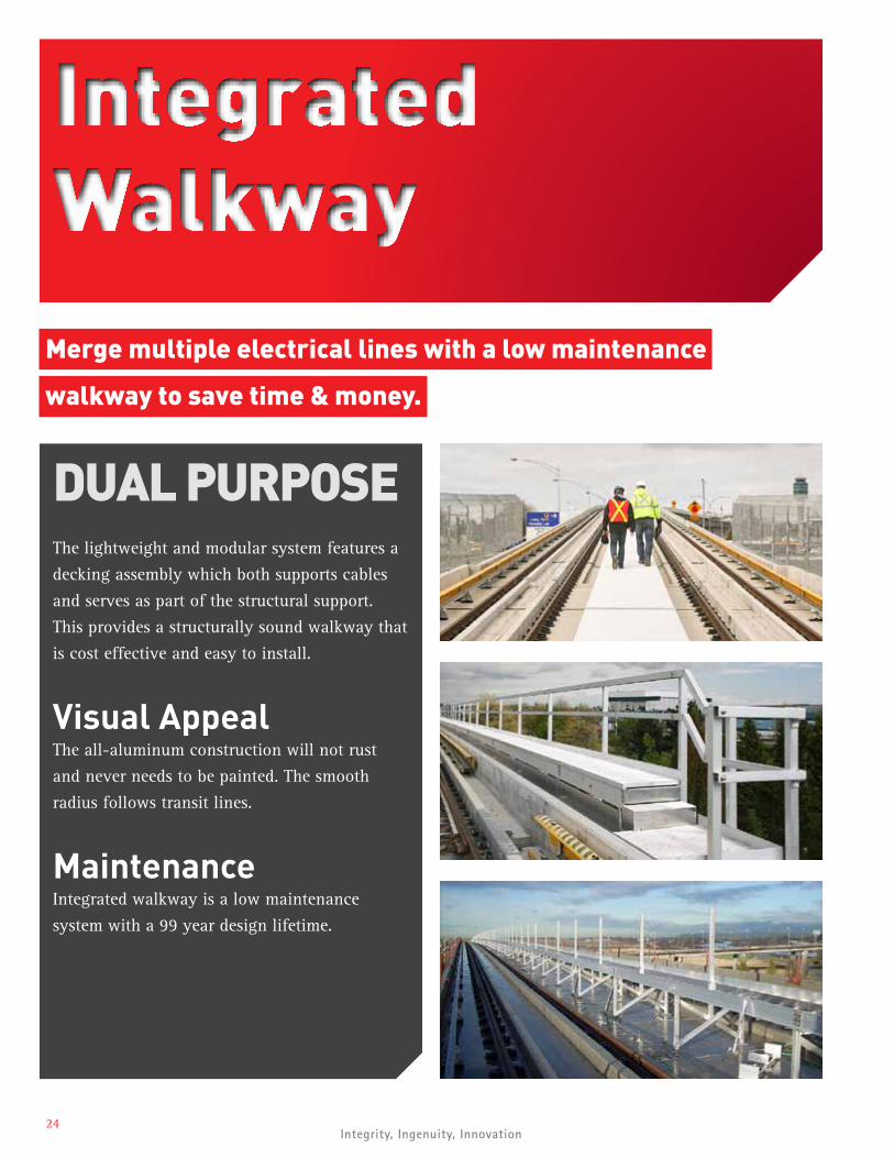
Integrated Walkway
Merge multiple electrical lines with a low maintenance
walkway to save time & money.
DUAL PURPOSEThe lightweight and modular system features a
decking assembly which both supports cables
and serves as part of the structural support.
This provides a structurally sound walkway that
is cost effective and easy to install.
Visual AppealThe all-aluminum construction will not rust
and never needs to be painted. The smooth
radius follows transit lines.
MaintenanceIntegrated walkway is a low maintenance
system with a 99 year design lifetime.
Super iorTray.com | 6 0 4 . 5 7 2 . 4 41 925
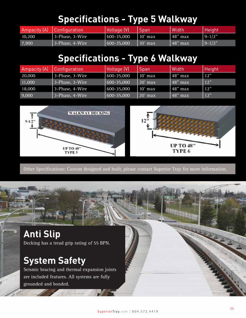
Specifications - Type 5 WalkwayAmpacity (A) Configuration Voltage (V) Span Width Height10,200 3-Phase, 3-Wire 600-35,000 10’ max 48” max 9-1/2”7,900 3-Phase, 4-Wire 600-35,000 10’ max 48” max 9-1/2”
Specifications - Type 6 WalkwayAmpacity (A) Configuration Voltage (V) Span Width Height20,000 3-Phase, 3-Wire 600-35,000 10’ max 48” max 12”11,000 3-Phase, 3-Wire 600-35,000 20’ max 48” max 12”18,000 3-Phase, 4-Wire 600-35,000 10’ max 48” max 12”9,000 3-Phase, 4-Wire 600-35,000 20’ max 48” max 12”
Anti SlipDecking has a tread grip rating of 55 BPN.
System SafetySeismic bracing and thermal expansion joints
are included features. All systems are fully
grounded and bonded.
Other Specifications: Custom designed and built, please contact Superior Tray for more information.
26Integrity, Ingenuity, Innovation
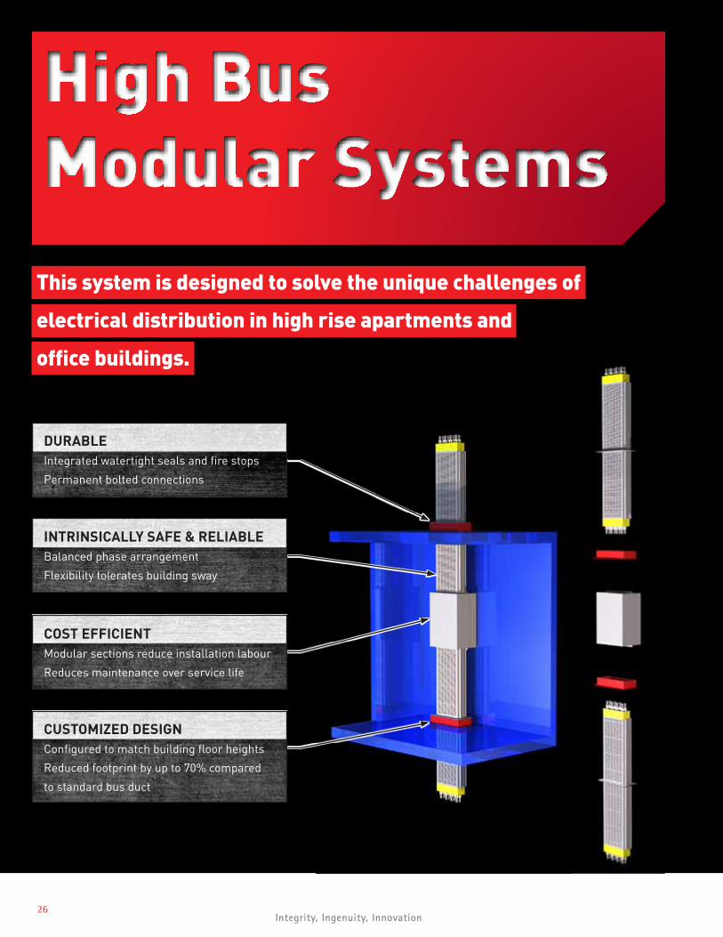
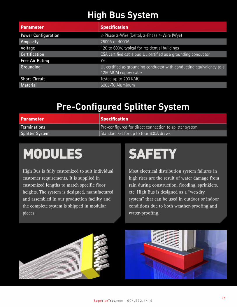
High BusModular Systems
This system is designed to solve the unique challenges of
electrical distribution in high rise apartments and
office buildings.
CUSTOMIZED DESIGNConfigured to match building floor heights
Reduced footprint by up to 70% compared
to standard bus duct
DURABLEIntegrated watertight seals and fire stops
Permanent bolted connections
INTRINSICALLY SAFE & RELIABLEBalanced phase arrangement
Flexibility tolerates building sway
COST EFFICIENTModular sections reduce installation labour
Reduces maintenance over service life
Super iorTray.com | 6 0 4 . 5 7 2 . 4 41 927
High Bus SystemParameter Specification
Power Configuration 3-Phase 3-Wire (Delta), 3-Phase 4-Wire (Wye)Ampacity 2500A or 4000AVoltage 120 to 600V, typical for residential buildingsCertification CSA certified cable bus, UL certified as a grounding conductorFree Air Rating YesGrounding UL certified as grounding conductor with conducting equivalency to a
1250MCM copper cableShort Circuit Tested up to 200 KAICMaterial 6063-T6 Aluminum
Pre-Configured Splitter SystemParameter Specification
Terminations Pre-configured for direct connection to splitter systemSplitter System Standard set for up to four 600A draws
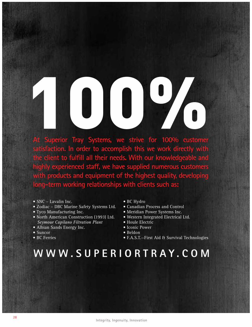
SAFETY Most electrical distribution system failures in
high rises are the result of water damage from
rain during construction, flooding, sprinklers,
etc. High Bus is designed as a “wet/dry
system” that can be used in outdoor or indoor
conditions due to both weather-proofing and
water-proofing.
MODULES High Bus is fully customized to suit individual
customer requirements. It is supplied in
customized lengths to match specific floor
heights. The system is designed, manufactured
and assembled in our production facility and
the complete system is shipped in modular
pieces.
28Integrity, Ingenuity, Innovation
•SNC–LavalinInc.•Zodiac–DBCMarineSafetySystemsLtd.•TycoManufacturingInc.•NorthAmericanConstruction(1993)Ltd. Seymour Capilano Filtration Plant•AlbianSandsEnergyInc.•Suncor•BCFerries
•BCHydro•CanadianProcessandControl•MeridianPowerSystemsInc.•WesternIntegratedElectricalLtd.•HouleElectric•IconicPower•Beldon•F.A.S.T.—FirstAid&SurvivalTechnologies
At Superior Tray Systems, we strive for 100% customer satisfaction. In order to accomplish this we work directly with the client to fulfill all their needs. With our knowledgeable and highly experienced staff, we have supplied numerous customers with products and equipment of the highest quality, developing long-term working relationships with clients such as:
W W W . S U P E R I O R T R A Y . C O M
Super iorTray.com | 6 0 4 . 5 7 2 . 4 41 929
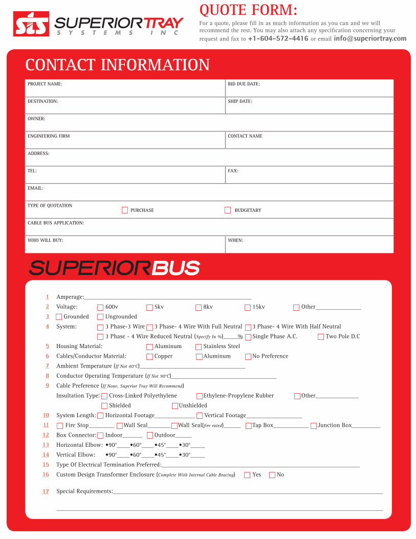
Amperage:
Voltage: 600v 5kv 8kv 15kv Other
Grounded Ungrounded
System: 3 Phase-3 Wire 3 Phase- 4 Wire With Full Neutral 3 Phase- 4 Wire With Half Neutral
3 Phase - 4 Wire Reduced Neutral (Specify In %) % Single Phase A.C. Two Pole D.C
Housing Material: Aluminum Stainless Steel
Cables/Conductor Material: Copper Aluminum No Preference
Ambient Temperature (If Not 40°C)
Conductor Operating Temperature (If Not 90°C)
Cable Preference (If None, Superior Tray Will Recommend)
Insultation Type: Cross-Linked Polyethylene Ethylene-Propylene Rubber Other
Shielded Unshielded
System Length: Horizontal Footage Vertical Footage
Fire Stop Wall Seal Wall Seal(fire rated) Tap Box Junction Box
Box Connector: Indoor Outdoor
HorizontalElbow:•90° •60° •45° •30°
VerticalElbow: •90° •60° •45° •30°
Type Of Electrical Termination Preferred:
Custom Design Transformer Enclosure (Complete With Internal Cable Bracing) Yes No
Special Requirements:
PROJECT NAME: BID DUE DATE:
DESTINATION: SHIP DATE:
OWNER:
ENGINEERING FIRM CONTACT NAME
ADDRESS:
TEL: FAX:
EMAIL:
TYPE OF QUOTATION PURCHASE BUDGETARY
CABLE BUS APPLICATION:
WHO WILL BUY: WHEN:
CONTACT INFORMATION
QUOTE FORM:For a quote, please fill in as much information as you can and we will recommend the rest. You may also attach any specification concerning your request and fax to +1-604-572-4416 or email [email protected]
1
2
3
4
5
6
7
8
9
10
11
12
13
14
15
16
17
30Integrity, Ingenuity, Innovation
Superior Tray Systems Inc.#12 – 13025 84th Avenue
Surrey, BCV3W 1B3
Tel: +1-604-572-4419Email: [email protected]: www.superiortray.com
superiortray.com Integrity, Ingenuity, Innovation