Embed Size (px)
Citation preview

A Product of
Sherwood, Oregon USA
WE-3 WATER EXTRACTOR PARTS MANUAL
S/N ASC-0WE3-001 ONLY
PB0WE32006
Page i -- Rev: 11/10
SAFETY
WARNING: Some illustrations in this parts list show the Water Extractor without shields to allow for a better view of the area being addressed. The Water Extractor should never be operated with any of the safety shields removed.
Do not clean, lubricate, or make any adjustments on the equipment while it is in operation.
Do not start the equipment until you are certain everyone is clear of the machine and have ensured there are no tools on the unit.
Do not work around equipment in loose clothing.
Do not attempt to service any equipment while the motor is running.
Inspection Covers and Safety Shields should only be removed by authorized service persons.
After servicing do not place the equipment back into operation until all Safety Shields and Devices have been replaced. Operation without Safety Shields and Devices can place the operator into a hazardous situation.
Do not open or work on the In-Feed System until the fl ow of material has been stopped and the Water Extractor Motor has been turned off.
Do not make any adjustments or reach under any load bearing surfaces while they are loaded.
INSTRUCT ALL OPERATORS ON SAFETY PRECAUTIONS.

Rev: 11/10 -- Page ii
INTRODUCTION
This manual contains illustrations and parts lists of components and assemblies which make up the machine. Each page consists of the name of the assembly or component, a reference number, part number, part name and the quantities of the part used.
Assembly or component names help identify the illustration and parts list for each fi gure. This name also helps locate the general area of the machine where the assembly or component can be located.
Reference numbers shown in a column refers to the numbered parts in the illustration. This ties the part in the illustration to the part number and description in the parts list. Part numbers are used to identify individual parts or part assemblies.
Part descriptions provide the name of the part, plus additional information such as dimensional specifi cation and what parts are grouped together to form part assemblies, which helps you identify the parts.
Quantities listed for each illustration are only for that assembly or component and not the total used per machine.
Indent dots are used to indicate assemblies and sub-parts of assemblies. No dot indicates the major assembly. Part descriptions which are indented with dots are sub-parts of the major assembly shown above.
Parts pages will be revised as necessary to show the latest parts information. Revision information will be on the bottom of the page
This parts manual is not intended to be a complete guide for machine service or repairs. Contact your dealer for any of your service or technical requirements.
HOW TO USE THE MANUAL
UPDATING AND REORDERING MAN U ALS
The parts lists, illustrations and specifi cations in this manual are based on the latest information available at the time of publication. Your machine may have product improvement and options not yet contained in this manual.
A copy of this manual is supplied with each machine. Additional copies are available through you dealer. When ordering additional manuals, use the reorder number listed on the front cover and the quantity needed.
Page iii Rev: 11/10
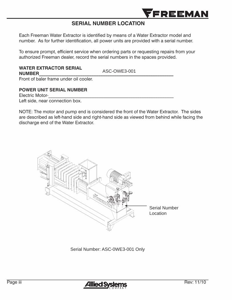
Each Freeman Water Extractor is identifi ed by means of a Water Extractor model and number. As for further identifi cation, all power units are provided with a serial number.
To ensure prompt, effi cient service when ordering parts or requesting repairs from your authorized Freeman dealer, record the serial numbers in the spaces provided.
WATER EXTRACTOR SERIAL NUMBER___________________________________________________________ Front of baler frame under oil cooler.
POWER UNIT SERIAL NUMBER Electric Motor-_______________________________________________________ Left side, near connection box.
NOTE: The motor and pump end is considered the front of the Water Extractor. The sides are described as left-hand side and right-hand side as viewed from behind while facing the discharge end of the Water Extractor.
SERIAL NUMBER LOCATION
Serial Number Location
Serial Number: ASC-0WE3-001 Only
ASC-OWE3-001
Rev: 11/10 Page iv
WE3 Assembly .............................................................................................................................. 2Infeed Chute .................................................................................................................................. 4Tension Rail Assembly................................................................................................................. 6Plunger Assembly ........................................................................................................................ 8Restriction Cylinder ................................................................................................................... 10Plunger Cylinder ......................................................................................................................... 12Tank Assembly............................................................................................................................ 14Junction Box ............................................................................................................................... 16Control Box ................................................................................................................................. 18Shields And Decals .................................................................................................................... 20
TABLE OF CONTENTS
Page 1 Rev: 11/10
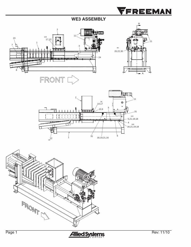
WE3 ASSEMBLY
A
A
11
20,22,30
4X
11
2
1
8
7 3
17,1312X
18,19,21,16
14,17
5,21,19,18
16,21,19,18
3X
14X
6
4
510,9
124X
2
1
11
23
24
14X
31
31
Rev: 11/10 Page 2
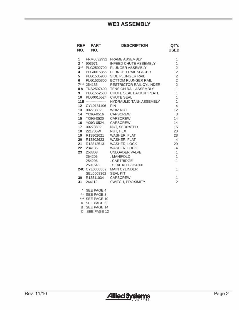
WE3 ASSEMBLY
REF PART DESCRIPTION QTY.NO. NO. USED
1 FRM0032932 FRAME ASSEMBLY 12 * 903971 INFEED CHUTE ASSEMBLY 13 ** PLG2592700 PLUNGER ASSEMBLY 24 PLG0015355 PLUNGER RAIL SPACER 25 PLG1535900 SIDE PLUNGER RAIL 26 PLG1535800 BOTTOM PLUNGER RAIL 27 *** 254185 RESTRICTOR RAIL CYLINDER 28 A TNS2597400 TENSION RAIL ASSEMBLY 19 PLG1552500 CHUTE SEAL BACKUP PLATE 110 PLG0015524 CHUTE SEAL 111B ----------------- HYDRAULIC TANK ASSEMBLY 112 CYL0181106 PIN 413 00273802 WHIZ NUT 12 14 Y09G-0516 CAPSCREW 315 Y09G-0520 CAPSCREW 1416 Y09G-0524 CAPSCREW 1417 00273802 NUT, SERRATED 1518 221705W NUT, HEX 28 19 R13802621 WASHER, FLAT 2820 R13802623 WASHER, FLAT 421 R13812513 WASHER, LOCK 2922 234135 WASHER, LOCK 423 253308 UNLOADER VALVE 1 254205 . MANIFOLD 1 254206 . CARTRIDGE 1 2501643 . SEAL KIT F/25420624 C CYL0003362 MAIN CYLINDER 1 SEL0003362 SEAL KIT30 R13811034 CAPSCREW 131 244112 SWITCH, PROXIMITY 2
* SEE PAGE 4 ** SEE PAGE 8 *** SEE PAGE 10 A SEE PAGE 6 B SEE PAGE 14 C SEE PAGE 12
Page 3 Rev: 11/10
1
9
2
3
3
15
14
3
6
8
5
7
13
7
12
1110
6
4
413
4
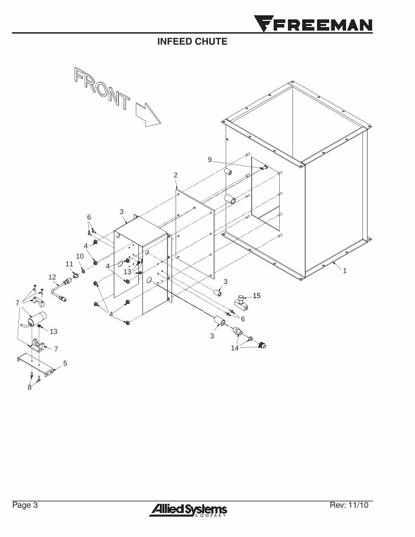
INFEED CHUTE
Rev: 11/10 Page 4
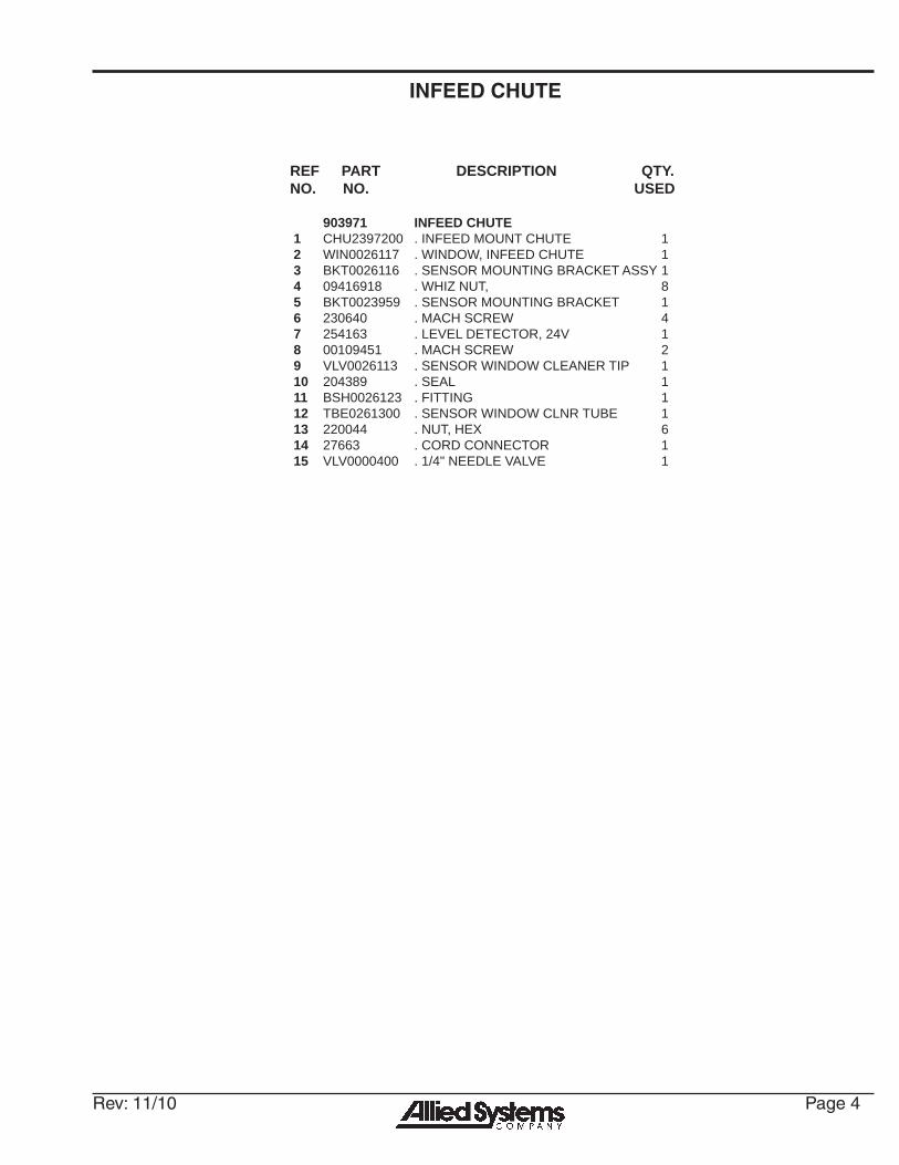
INFEED CHUTE
REF PART DESCRIPTION QTY.NO. NO. USED
903971 INFEED CHUTE1 CHU2397200 . INFEED MOUNT CHUTE 12 WIN0026117 . WINDOW, INFEED CHUTE 13 BKT0026116 . SENSOR MOUNTING BRACKET ASSY 14 09416918 . WHIZ NUT, 85 BKT0023959 . SENSOR MOUNTING BRACKET 16 230640 . MACH SCREW 47 254163 . LEVEL DETECTOR, 24V 18 00109451 . MACH SCREW 29 VLV0026113 . SENSOR WINDOW CLEANER TIP 110 204389 . SEAL 111 BSH0026123 . FITTING 112 TBE0261300 . SENSOR WINDOW CLNR TUBE 113 220044 . NUT, HEX 6 14 27663 . CORD CONNECTOR 115 VLV0000400 . 1/4" NEEDLE VALVE 1

Page 5 Rev: 11/10
TENSION RAIL ASSEMBLY
DETAIL A
A
1
2
3
4
5
6
7
8
9
9
810

Rev: 11/10 Page 6
TENSION RAIL ASSEMBLY
REF PART DESCRIPTION QTY.NO. NO. USED
TNS2597400 RESTRICTOR RAIL ASSEMBLY1 TNS0025974 . RESTRICTION RAIL 12 WIP0021095 . TENSION RAIL WIPER 23 WIP2105400 . WIPER SUPPORT 24 SCOS000312 . FLAT HD SOC (SS) 185 WAS0000143 . 3/8" MALLEABLE BEVEL WASHER 186 231851 . NUT, ESNA; NC (SS) 187 237642 . CAPSCREW; (SS) 28 234173 . WASHER, FLAT; (SS) 49 BSH00VG275 . BUSHING 210 233852 . NUT, ESNA; NC (SS) 2
Page 7 Rev: 11/10
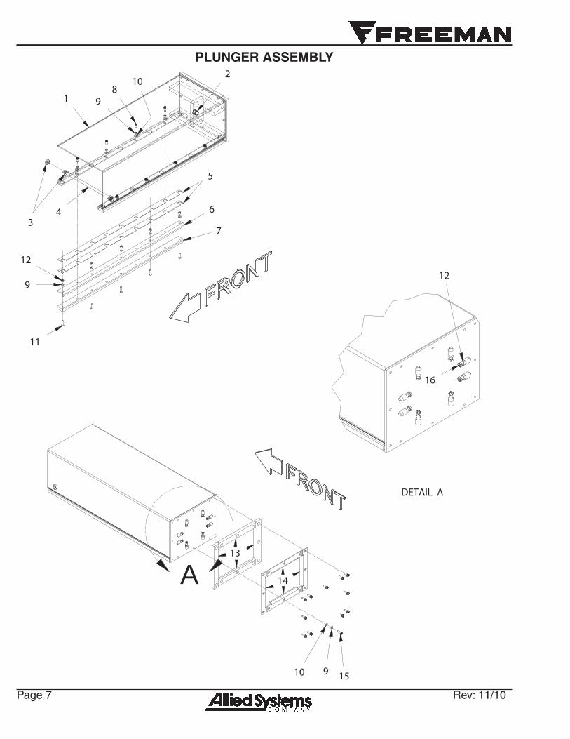
PLUNGER ASSEMBLY
1
2
3 4
5
6
7
89
10
11
9
12
DETAIL A
A13
14
910 15
12
16
Rev: 11/10 Page 8
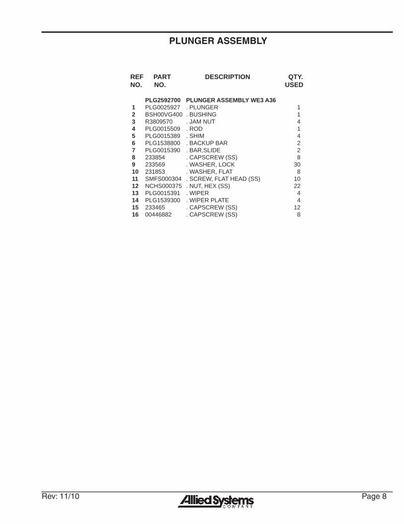
PLUNGER ASSEMBLY
REF PART DESCRIPTION QTY.NO. NO. USED
PLG2592700 PLUNGER ASSEMBLY WE3 A361 PLG0025927 . PLUNGER 12 BSH00VG400 . BUSHING 13 R3809570 . JAM NUT 44 PLG0015509 . ROD 15 PLG0015389 . SHIM 46 PLG1538800 . BACKUP BAR 27 PLG0015390 . BAR,SLIDE 28 233854 . CAPSCREW (SS) 89 233569 . WASHER, LOCK 3010 231853 . WASHER, FLAT 811 SMFS000304 . SCREW, FLAT HEAD (SS) 1012 NCHS000375 . NUT, HEX (SS) 2213 PLG0015391 . WIPER 414 PLG1539300 . WIPER PLATE 415 233465 . CAPSCREW (SS) 1216 00446882 . CAPSCREW (SS) 8

Page 9 Rev: 11/10
RESTRICTION CYLINDER
1 78
121615
41413211
5613143910
Rev: 11/10 Page 10
RESTRICTION CYLINDER
REF PART DESCRIPTION QTY.NO. NO. USED
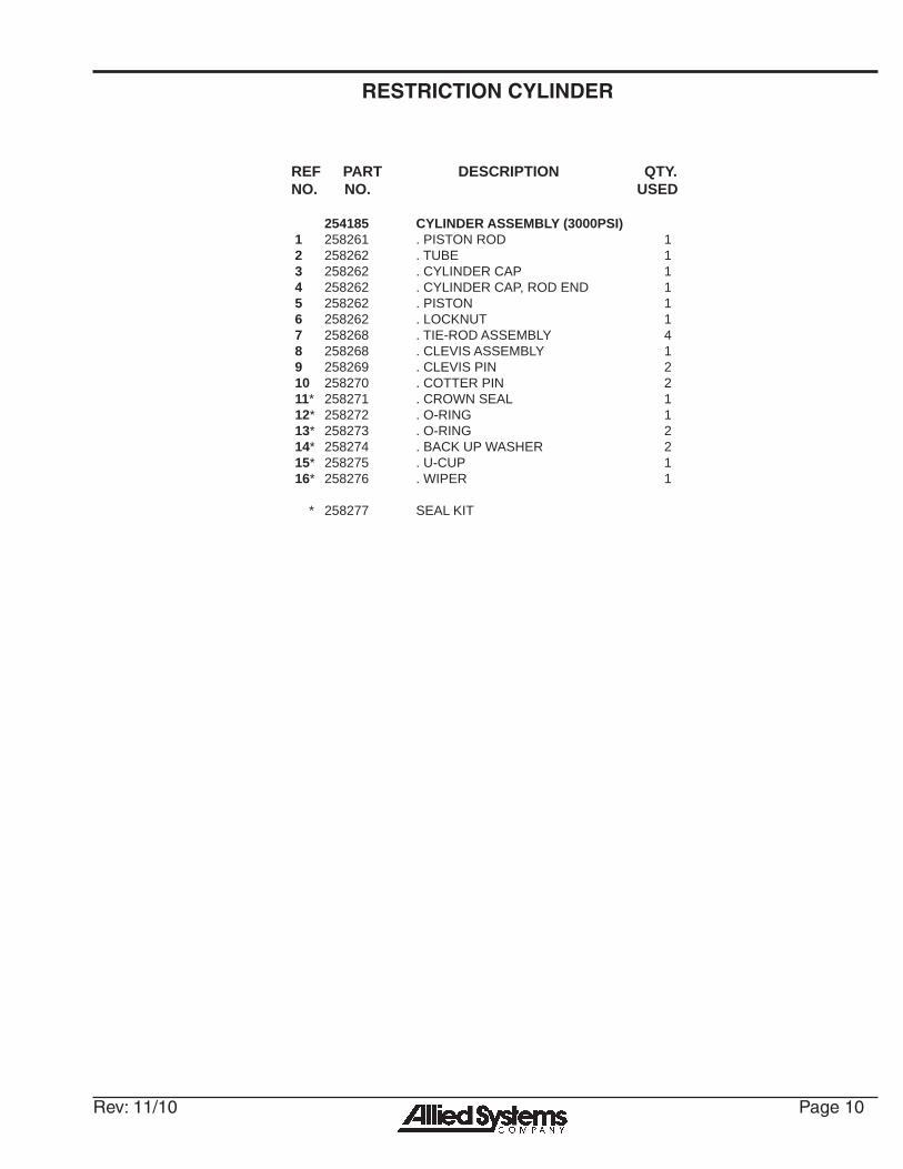
254185 CYLINDER ASSEMBLY (3000PSI) 1 258261 . PISTON ROD 12 258262 . TUBE 13 258262 . CYLINDER CAP 14 258262 . CYLINDER CAP, ROD END 15 258262 . PISTON 16 258262 . LOCKNUT 17 258268 . TIE-ROD ASSEMBLY 48 258268 . CLEVIS ASSEMBLY 19 258269 . CLEVIS PIN 210 258270 . COTTER PIN 211 * 258271 . CROWN SEAL 112 * 258272 . O-RING 113 * 258273 . O-RING 214 * 258274 . BACK UP WASHER 2 15 * 258275 . U-CUP 116 * 258276 . WIPER 1
* 258277 SEAL KIT
Page 11 Rev: 11/10
PLUNGER CYLINDER
1 2 3 4 5 6 713
13
8 9 10 9 11 12
Rev: 11/10 Page 12
PLUNGER CYLINDER
REF PART DESCRIPTION QTY.NO. NO. USED
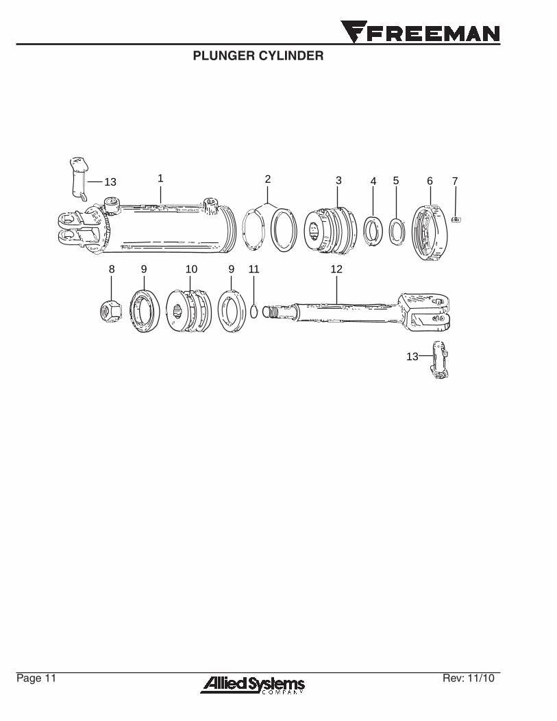
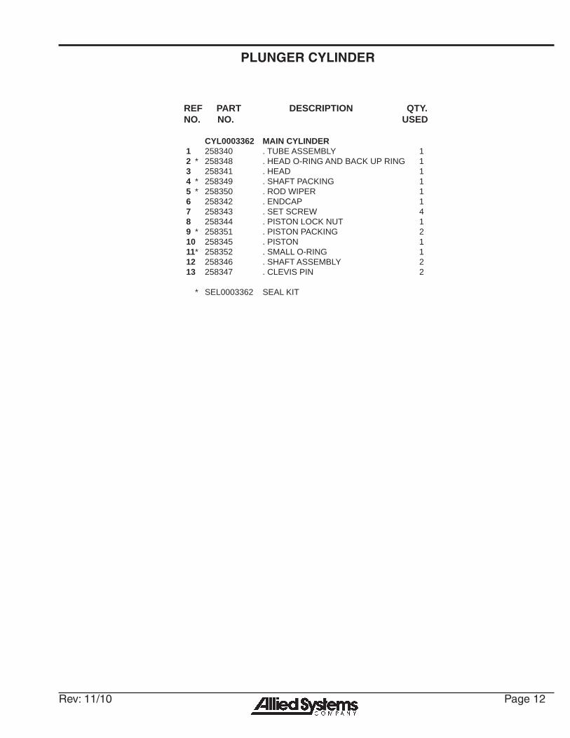
CYL0003362 MAIN CYLINDER 1 258340 . TUBE ASSEMBLY 12 * 258348 . HEAD O-RING AND BACK UP RING 13 258341 . HEAD 14 * 258349 . SHAFT PACKING 15 * 258350 . ROD WIPER 16 258342 . ENDCAP 17 258343 . SET SCREW 48 258344 . PISTON LOCK NUT 19 * 258351 . PISTON PACKING 210 258345 . PISTON 111 * 258352 . SMALL O-RING 112 258346 . SHAFT ASSEMBLY 213 258347 . CLEVIS PIN 2
* SEL0003362 SEAL KIT
Page 13 Rev: 11/10
1
2
3 4,5,6
30
207
8
9
10 1112
13
4,5,6
15
18
18
7
22
21
18
22
23
21 187
18
15
29
30
31
25
26
27
28
20
19
25262728
14
2
Junction BoxSee Page 16
Control BoxSee Page 18
14
1819
23
24
18
18
32
16 17
16
17
31
31
TANK ASSEMBLY
Rev: 11/10 Page 14
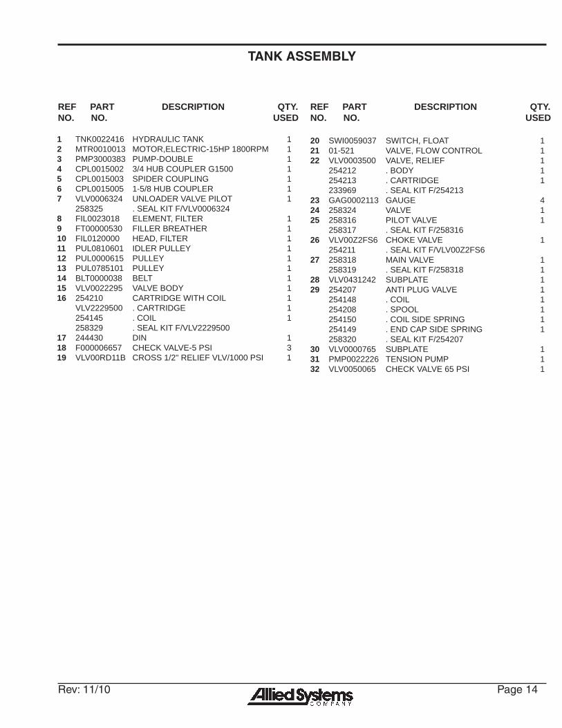
TANK ASSEMBLY
REF PART DESCRIPTION QTY.NO. NO. USED
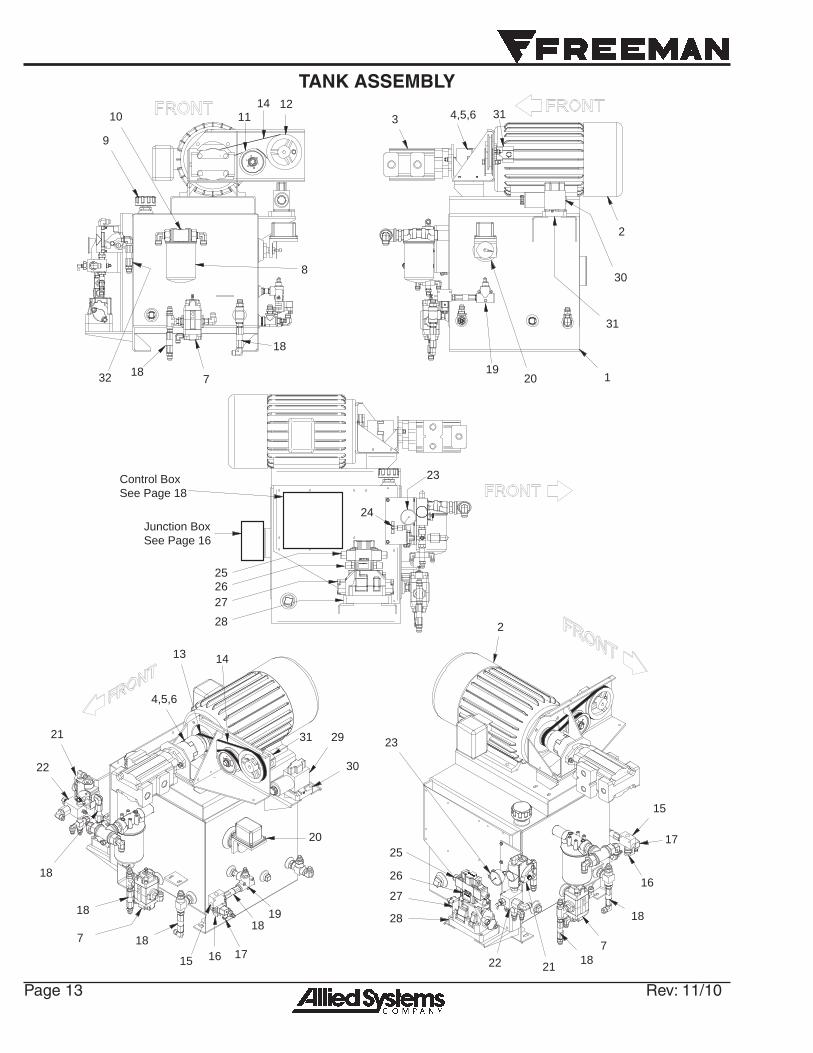
1 TNK0022416 HYDRAULIC TANK 12 MTR0010013 MOTOR,ELECTRIC-15HP 1800RPM 13 PMP3000383 PUMP-DOUBLE 14 CPL0015002 3/4 HUB COUPLER G1500 15 CPL0015003 SPIDER COUPLING 16 CPL0015005 1-5/8 HUB COUPLER 17 VLV0006324 UNLOADER VALVE PILOT 1 258325 . SEAL KIT F/VLV00063248 FIL0023018 ELEMENT, FILTER 19 FT00000530 FILLER BREATHER 110 FIL0120000 HEAD, FILTER 111 PUL0810601 IDLER PULLEY 112 PUL0000615 PULLEY 113 PUL0785101 PULLEY 114 BLT0000038 BELT 115 VLV0022295 VALVE BODY 116 254210 CARTRIDGE WITH COIL 1 VLV2229500 . CARTRIDGE 1 254145 . COIL 1 258329 . SEAL KIT F/VLV222950017 244430 DIN 118 F000006657 CHECK VALVE-5 PSI 319 VLV00RD11B CROSS 1/2" RELIEF VLV/1000 PSI 1
20 SWI0059037 SWITCH, FLOAT 121 01-521 VALVE, FLOW CONTROL 122 VLV0003500 VALVE, RELIEF 1 254212 . BODY 1 254213 . CARTRIDGE 1 233969 . SEAL KIT F/25421323 GAG0002113 GAUGE 424 258324 VALVE 125 258316 PILOT VALVE 1 258317 . SEAL KIT F/25831626 VLV00Z2FS6 CHOKE VALVE 1 254211 . SEAL KIT F/VLV00Z2FS627 258318 MAIN VALVE 1 258319 . SEAL KIT F/258318 128 VLV0431242 SUBPLATE 129 254207 ANTI PLUG VALVE 1 254148 . COIL 1 254208 . SPOOL 1 254150 . COIL SIDE SPRING 1 254149 . END CAP SIDE SPRING 1 258320 . SEAL KIT F/25420730 VLV0000765 SUBPLATE 131 PMP0022226 TENSION PUMP 132 VLV0050065 CHECK VALVE 65 PSI 1
REF PART DESCRIPTION QTY.NO. NO. USED

Page 15 Rev: 11/10
BO
X S
HO
WN
WIT
H L
IDR
EM
OV
ED
FO
R C
LAR
ITY
1
2
3
4
JUNCTION BOX

Rev: 11/10 Page 16
JUNCTION BOX
REF PART DESCRIPTION QTY.NO. NO. USED
ELC2459700 JUNCTION BOX ELECTRICAL GROUP1 BOX0030145 . JUNCTION BOX 12 PNL0024594 . JUNCTION BOX PANEL 13 MSR0010140 . MARKER STRIP 10 POST 14 BAB0010140 . BARRIER BLOCK 10 POST 1
Page 17 Rev: 11/10
CONTROL BOX

Rev: 11/10 Page 18
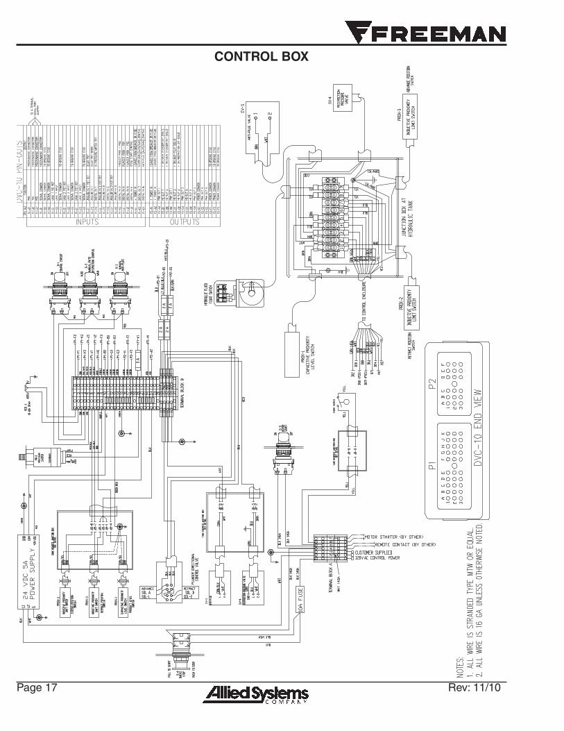
CONTROL BOX
REF PART DESCRIPTION QTY.NO. NO. USED
902229 CONTROL PANEL ASSEMBLY WE-31 28286 BACK PANEL 12 902230 PROGRAMMED MOD CONTROLLER 13 254146 POWER SUPPLY 24 V DC, 5 A 17 SWI0096201 ADJUSTABLE PRESSURE SWITCH 18 241309 2 POS SWITCH 49 245511 OPERATOR, PUSH-PULL 110 245512 BUTTON; EMERGENCY STOP, RED 112 ELC7531010 POTENTIOMETER 113 KOB0001P2B POTENTIOMETER KNOB 114 17511 FUSE HOLDER (SURFACE MOUNT) 115 20313 FUSE HOLDER COVER 1
33
3
12,13 34 27
1
14,15,18
40
2522
25 22 22 24 21
10,30,35
27,34 28,34 29,34
31,34
36,37,38
35
2
REF PART DESCRIPTION QTY.NO. NO. USED
18 241791 FUSE 10A 121 247209 DIODE TERMINAL BLOCK 422 239317 TERMINAL BLOCK 1924 232239 JUMPER 1325 232238 PLATE END 327 901768 DECAL, CONTROL CIRCUIT 128 901769 DECAL, RESTRICTION 129 901770 DECAL, ANTI PLUG 130 901771 DECAL, EMERGENCY STOP 131 901772 DECAL, MOTOR START 133 902228 WE3 ENCLOSURE 134 256203 2 POS SEL SW MAINT 435 256204 EM STOP PUSH/PULL MAINT 1
Page 19 Rev: 11/10
SHIELDS AND DECALS
1
2
3
4
5
6
7
8
9
9
8
10
9
Rev: 11/10 Page 20
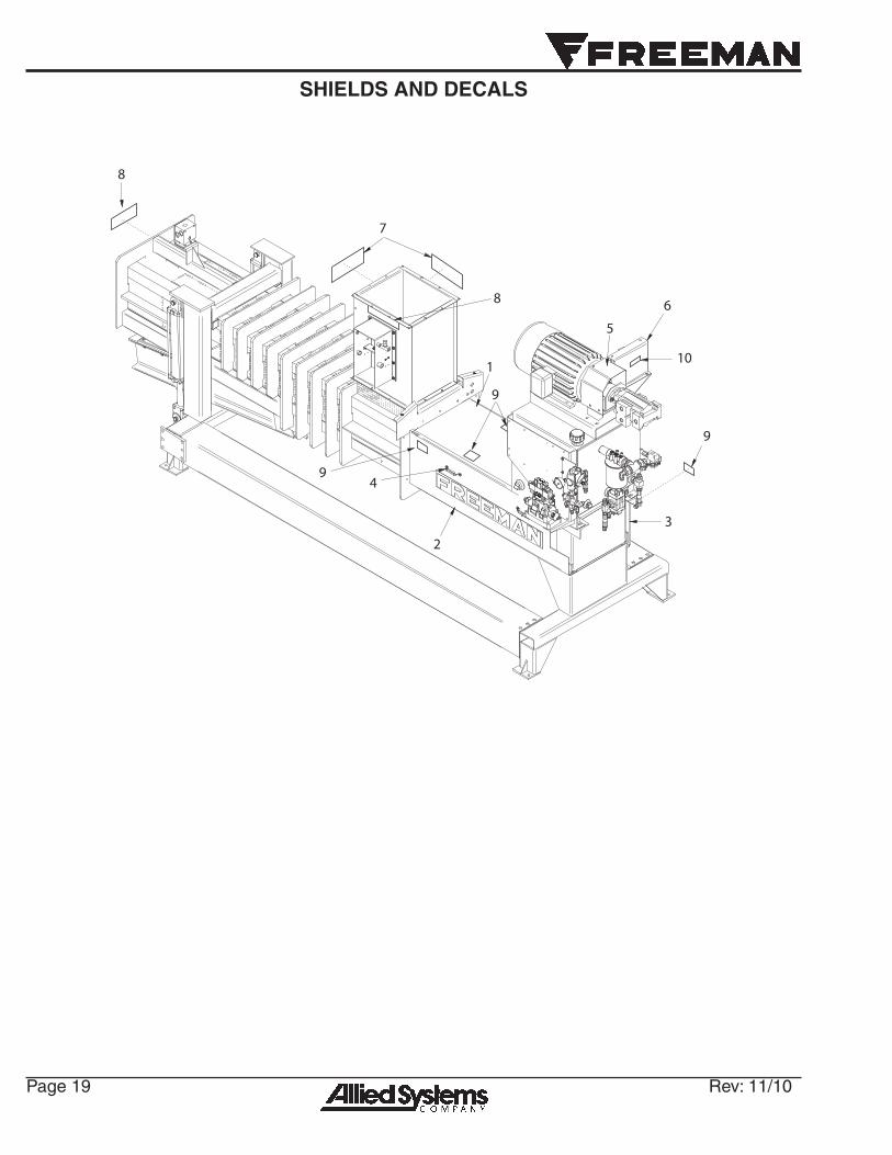
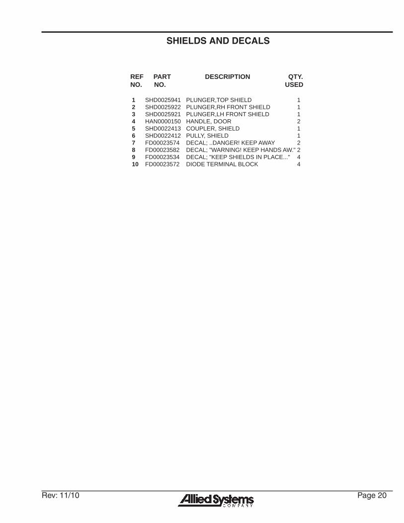
SHIELDS AND DECALS
REF PART DESCRIPTION QTY.NO. NO. USED
1 SHD0025941 PLUNGER,TOP SHIELD 12 SHD0025922 PLUNGER,RH FRONT SHIELD 13 SHD0025921 PLUNGER,LH FRONT SHIELD 14 HAN0000150 HANDLE, DOOR 25 SHD0022413 COUPLER, SHIELD 16 SHD0022412 PULLY, SHIELD 17 FD00023574 DECAL; ..DANGER! KEEP AWAY 28 FD00023582 DECAL; "WARNING! KEEP HANDS AW." 29 FD00023534 DECAL; "KEEP SHIELDS IN PLACE..." 410 FD00023572 DIODE TERMINAL BLOCK 4

To fi nd a dealer in your area,Call: 503-625-2560Fax: 503-625-7269
Visit our website: http//www.alliedsystems.comPB0WE32006 11/10
Printed in USA