Embed Size (px)
Citation preview
Abstract— The wire electrical discharge machining process
(WEDM) is largely employed in the metal mechanic industry -
especially in its tooling sector, as tools generally have complex
geometry and are made of hard materials with low usinability,
which hinders the application of conventional machining
processes. This work presents an investigation of the influence
of the cutting parameters in the WEDM process of the VC131
tool steel. A FANUC ROBOCUT α-OiE equipment was used in
the experiments. The machining of the VC131 steel in the ‘as
supplied’ condition (untreated), with a hardness of 19 HRC,
and after a quench and temper heat treatment, with a hardness
of 53 HRC, was analysed. This work aims to compare the
cutting parameters generated by the equipment, which are
based on technical tables, with those optimized by the operator.
In this study, the machining time, the material removal rate and
the surface finishing obtained before and after the optimization
of the cutting parameters were compared. There was an
important gain in the material removal rate and a small loss in
the surface finishing when the machine parameters were
adjusted to improve the performance of the machining process
of the VC131 tool steel before and after the heat treatment.
Index Terms — Wire electrical discharge machining. Steel.
Material removal rate.
I. INTRODUCTION
HE wire electrical discharge machinig (WEDM) process
offers great advantages, as it is a cutting method that
may be applied to any electrical conductor, hardened (heat
treated) materials included. Besides, a stress relieving
treatment after machining is not required and the material
microstructure is not affected by the process. During the
machining process, the wire, which serves as electrode,
follows a pre-programmed path that may be determined
either by manual input into the machine’s control panel or by
using a specific CAM software. The use of this process
enhances the competitiveness of industries, as it allows them
to offer precision products with complex geometries.
II. LITERATURE REVIEW
The companies of the metal mechanic sector, especially
the tool makers, frequently use the VC131 tool steel for
making parts and tools to be used in production. However, a
A. Jefferson is with the Department of Machining, College SENAI
Campinas, São Paulo - Brazil ([email protected]).
C. Balbino is with the Department of Machining, College SENAI
Campinas, São Paulo - Brazil ([email protected]).
W. Thomas is with the Department of Machining, College SENAI
Campinas, São Paulo - Brazil ([email protected]).
A. Hassui is with the Department of Mechanical, University of
Campinas, São Paulo - Brazil ([email protected])
great issue faced by those companies is related to the
difficulties in machining heat treated materials without
affecting their mechanical properties.
According to Dibitongo et al (1989), the electrical
discharge machining process (EDM) has attracted attention
of industries as it is a technical advance that allows for the
machining of parts with varied and complex geometries, that
would be difficult or even impossible to obtain through other
traditional machining processes, such as milling and drilling.
As stated by Uddeholm (2002), the temperature at the cut
region may reach up to 50,000 °C during the electrical
discharge machining process. However, this process has
some advantages when compared to traditional machining
process, as in those processes physical contact between the
cutting tool and the part is required, whereas such contact
does not happen in the electrical discharge process.
Consequently, no mechanical force is applied on the surface
of the machined part, which allows for preserving the
microstructure of its material.
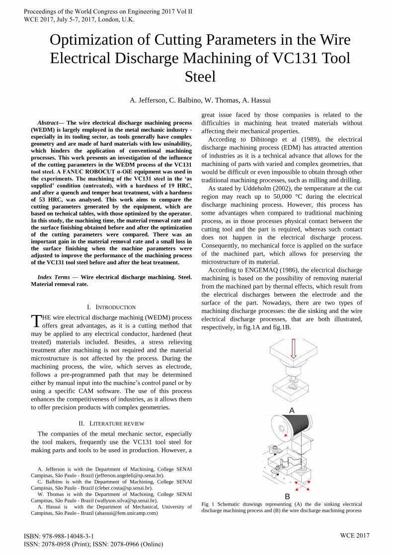
According to ENGEMAQ (1986), the electrical discharge
machining is based on the possibility of removing material
from the machined part by thermal effects, which result from
the electrical discharges between the electrode and the
surface of the part. Nowadays, there are two types of
machining discharge processes: the die sinking and the wire
electrical discharge processes, that are both illustrated,
respectively, in fig.1A and fig.1B.
A
B
Fig 1 Schematic drawings representing (A) the die sinking electrical
discharge machining process and (B) the wire discharge machining process
Optimization of Cutting Parameters in the Wire
Electrical Discharge Machining of VC131 Tool
Steel
A. Jefferson, C. Balbino, W. Thomas, A. Hassui
T
Proceedings of the World Congress on Engineering 2017 Vol II WCE 2017, July 5-7, 2017, London, U.K.
ISBN: 978-988-14048-3-1 ISSN: 2078-0958 (Print); ISSN: 2078-0966 (Online)
WCE 2017
As stated by Sommer et al (1994), in both types of
processes, the upper head of the machine and the base tank
embody the positive and negative terminals, which are key
parts of the electrical circuit. During the cutting process, the
part is immersed in dielectric fluid, which may be either
deionized water or oil and serves insulator and cooling fluid.
When the wire approaches the part and the insulating
resistance of the dielectric is breached by the electric tension
that exists between the wire and the surface of the part, an
electric current between both appears and causes the opening
of a slit on the part’s surface. That slit is then filled by
dielectric fluid.
As stated by Sommer (1994), the mechanical properties of
the wire employed as electrode in the WEDM process are of
key-importance, as well as its melting point. In turn, both
characteristics are directly related to its chemical
composition. In this process, it is desirable that the wire is
slightly worn out in order to prevent short-circuits.
According to Sommer et al (1994), the process of
removing material by using electrical discharges is in use
since the 1950s. Nonetheless, it was only in 1969 that the
Swiss company Agie produced the world’s first electrical
discharge machine. Initially, the equipment was capable of
machining with cutting speeds (Vw) as high as 21.5
mm2/min. Years later, in the beginning of the 1980’s,
equipments that followed the same concept but incorporated
new technologies allowed for machining with cutting speeds
as high as 64.5 mm2/min. As stated by Hespanhos et al
(2009), the wire electrical discharge machines have greatly
evolved during the last years, and nowadays they’re capable
of working with cutting speeds as high as 500 mm2/min.
The cutting speed, determined in mm2/min, is related to
the equipment’s capability of machining materials.
According to GF Agie-Charmilles (2007), the technological
evolution made it possible to obtain a good surface finish in
the machining of surfaces, with average roughness as small
as 0.05 μm (N3 class).
The most important parameters in the wire electrical
discharge machining process are:
VM: Machining electric voltage [ V ];
T: Wire tension [ g ];
WF: Wire feeding speed [ m/min ];
FR: Water flux [ l/min ].
The VM parameter is related to the adjustment of the
amplitude of the electric pulses responsible for the cutting.
The bigger the VM value, the greater is the peak amplitude
of the electric pulses and, therefore, the cutting speed. Still,
as VM grows, the wire tends to break more easily.
The T parameter is important in reducing vibration during
the machining process, which affects the precision of the cut.
Generally, the bigger the T value, the smaller is the
vibration. However, an increment in T in rough machining
makes the wire more prone to rupture.
The wire feeding speed (WF), on its turn, is proportional
to the cutting speed. For an example, in rough machine
operations, where higher cutting speeds are used, the wire
thins out quicker than in finishing operations – that happens
because of the greater wear caused by the more intense
electrical discharges in the first type of operation.
The water flux (FR) consists in the amount of dielectric
fluid that is injected in the system per unit of time and,
therefore, to the speed of the fluid that leaves the injection
nozzle. The greater the jet speed, the greater is the wire
vibration and, hence, the cut precision decreases.
III. EXPERIMENTAL PROCEDURE
The experiments took place in the wire electrical
discharge machining laboratory of the SENAI “Roberto
Mange” Faculty of Technology. A FANUC WEDM CNC
machine was used. The machine was of the ROBOCUT α-
OiE model and had a command of the FANUC Séries 31i-
WA type.
Initially, the WEDM machining tests were performed with
typical cutting parameters, that were generated by the
equipment and based on its technical tables. After, those
parameters were optimized to improve the cutting efficiency
and the material removing rate. The cutting parameters
generated by the machine and the optimized ones are shown
in Table I.
Test specimens were machined from VC131 tool steel in
two conditions: as supplied, with a hardness of 19 HRC, and
after a quench and temper heat treatment, with a hardness of
53 HRC. The chemical compositions of the test specimens
was evaluated through a spectrometry chemical analysis
made by the SGS Labmat Análises e Ensaios de Materiais
Ltda. The results of the analysis are shown in Table II.
After the WEDM experiments were performed, the
hardness of the cut surfaces of the specimens was measured
using a FUTURE-TECH (model LC-200RB) table
durometer. Five indentations were made on the cut surface
of each sample; of those, the two first measurements were
discarded and the three last ones were used to calculate the
average hardness on the surfaces.
Measurements for the evaluation of the surface finish of
the machined parts were made using a portable surface
roughness tester of the model Mahr – MarSurf M300C. For
each part, the measurements were performed on three
different regions on the cut surface. Then, the values
obtained from the three measures were used to calculate the
average surface roughness.
TABLE I
CUTTING PARAMETERS GENERATED BY THE MACHINE AND
THEIR OPTIMIZED VALUES.
Parameter Machine Optimized
VM [V] 31 34
T [g] 1300 1000
WF [m/min] 10 15
FR [l/min] 15 18
TABLE II
CHEMICAL COMPOSITION OF THE VC131 TOOL STEEL USED.
C Si Mn P Cr W 1.910% 0.270% 0.617% 0.001% 10.931% 0.609%
Ni Mo Cu V Co Fe 0.134% 0.009% 0.045% 0.125% 0.025% BASE
Proceedings of the World Congress on Engineering 2017 Vol II WCE 2017, July 5-7, 2017, London, U.K.
ISBN: 978-988-14048-3-1 ISSN: 2078-0958 (Print); ISSN: 2078-0966 (Online)
WCE 2017
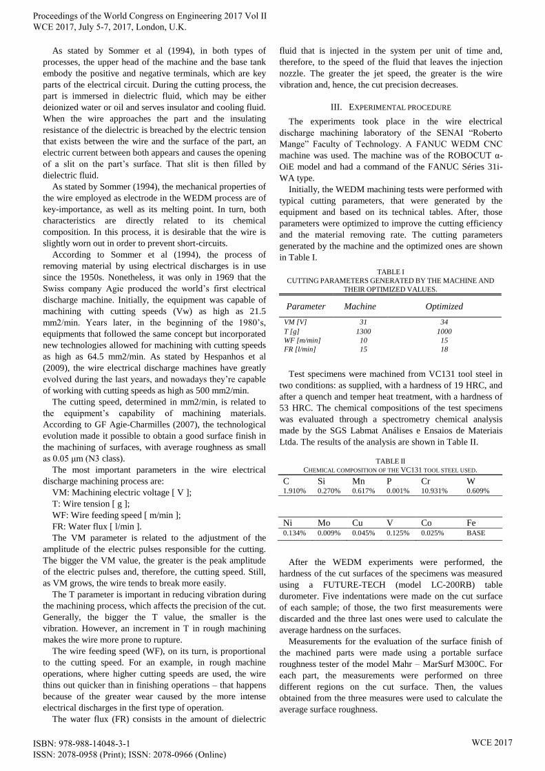
For each machining condition, three straight cuts,
perpendicular to the length of the VC131 test specimens,
were made. The cut sections were of square geometry, they
had 37.50 mm sides and a cut area of 1406 mm2. The cuts
were made with a 5 mm spacing between them, as depicted
in fig.2.
Fig 2 Experimental set up and geometry of the machined cuts.
In the experiments, the material was fixed to the machine's
work table according to the information contained in the
equipment operations manual and the manufacturer's
recommendations. An uncoated Ø 0.25 mm Extra Hard 900
N/mm² brass wire tool-electrode, supplied by KAMETAL,
was used. The electrode presents an elongation of 2 - 2.5 %
and its composition follows the ASTM B-36 standard (63%
Cu + 37% Zn).
In each experiment, the PM 21 cutting mode was used, as
it is recommended for rough machining operations by the
equipment’s manufacturer.
The debris from the cutting operation were removed by
0.8 bar water jets, which were discharged by the upper and
down nozzles of the machine heads, as recommended by the
equipment’s manufacturer for the employed wire diameter.
IV. RESULTS
The first part of the experiment was performed using the
cutting parameters that were generated by the machine
software after it was inputted with the following variables:
part’s material, wire diameter and cut thickness. It was
observed that the machine software generated the same
parameters for the ‘as supplied’ material, herein called
untreated material, and the heat treated material.
The average machining time, linear cutting speeds and
material removal rates were registered. For each test
condition, three samples were used. The results are
described in Table III, and they indicate that the cut
operations were well succeeded.
In the first experiment, the material of the test specimen
was the VC131 tool steel in the untreated condition, with no
heat treatment and presenting a hardness of 19 HRC. The
cutting parameters generated by the equipment’s software
were used. In these conditions, the recorded values for the
average machining time, average cutting speed and average
surface roughness (Ra) were 12 min and 10 s, 3.082 mm/min
and Ra 2.541 µm, respectively.
In the second experiment, the test specimens’ material and
the set up were the same as in the first one, with the
difference that the optimized cutting parameters were used.
It was observed that the average cutting speed increased to
3.739 mm/min, which corresponded to a reduction in the
machining time from 12 min 10 s to 10 min 02 s, and a slight
increase in the cut surface average roughness to Ra 2.813
µm.
In the third experiment, the material of the test specimen
was the heat treated VC131 tool steel, which had a hardness
of 53 HRC. The cutting parameters generated by the
equipment’s software were used. In this case, the recorded
values for the average machining time, average cutting speed
and average surface roughness (Ra) were 10 min and 36 s,
3.5382 mm/min and Ra 2.652 µm, respectively.
In the fourth experiment, the test specimens’ material and
the set up were the same as in the third one, with the
difference that the optimized cutting parameters were used.
It was observed that the average cutting speed increased
from 3.5382 mm/min to 4.131 mm/min, the machining time
was reduced to 9 min and 05 s, and the obtained cut surface
average roughness was Ra 2.899 µm.
TABLE III
AVERAGE MACHINING TIMES, LINEAR CUTTING SPEEDS AND MATERIAL
REMOVAL RATES OBTAINED IN THE TESTED EXPERIMENTAL CONDITIONS.
PARAMETERS
MACHINE OPTIMIZED
‘AS
SUPPLIED’
UNTREATED
VC131 TOOL
STEEL
19 HRC
QUENCHED
AND
TEMPERED
VC131 TOOL
STEEL
53 HRC
‘AS
SUPPLIED’
UNTREATED
VC131 TOOL
STEEL
19 HRC
QUENCHED
AND
TEMPERED
VC131 TOOL
STEEL
53 HRC
Machining
time [min] 12.172 10.600 10.039 9.078
Linear
cutting
speed
[mm/min]
3.082 3.538 3.739 4.131
Material
removal rate
[mm²/min]
115.5 132.7 140.1 154.9
Proceedings of the World Congress on Engineering 2017 Vol II WCE 2017, July 5-7, 2017, London, U.K.
ISBN: 978-988-14048-3-1 ISSN: 2078-0958 (Print); ISSN: 2078-0966 (Online)
WCE 2017
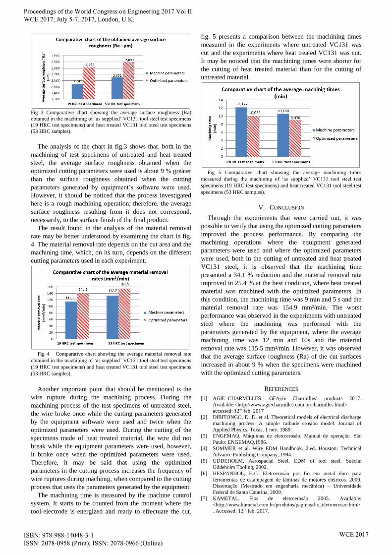
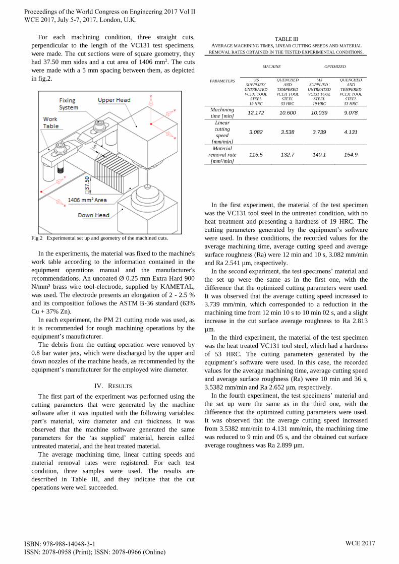
Fig 3 Comparative chart showing the average surface roughness (Ra)
obtained in the machining of ‘as supplied’ VC131 tool steel test specimens
(19 HRC test specimens) and heat treated VC131 tool steel test specimens
(53 HRC samples).
The analysis of the chart in fig.3 shows that, both in the
machining of test specimens of untreated and heat treated
steel, the average surface roughness obtained when the
optimized cutting parameters were used is about 9 % greater
than the surface roughness obtained when the cutting
parameters generated by equipment’s software were used.
However, it should be noticed that the process investigated
here is a rough machining operation; therefore, the average
surface roughness resulting from it does not correspond,
necessarily, to the surface finish of the final product.
The result found in the analysis of the material removal
rate may be better understood by examining the chart in fig.
4. The material removal rate depends on the cut area and the
machining time, which, on its turn, depends on the different
cutting parameters used in each experiment.
Fig 4 Comparative chart showing the average material removal rate
obtained in the machining of ‘as supplied’ VC131 tool steel test specimens
(19 HRC test specimens) and heat treated VC131 tool steel test specimens
(53 HRC samples).
Another important point that should be mentioned is the
wire rupture during the machining process. During the
machining process of the test specimens of untreated steel,
the wire broke once while the cutting parameters generated
by the equipment software were used and twice when the
optimized parameters were used. During the cutting of the
specimens made of heat treated material, the wire did not
break while the equipment parameters were used, however,
it broke once when the optimized parameters were used.
Therefore, it may be said that using the optimized
parameters in the cutting process increases the frequency of
wire ruptures during machinig, when compared to the cutting
process that uses the parameters generated by the equipment.
The machining time is measured by the machine control
system. It starts to be counted from the moment where the
tool-electrode is energized and ready to effectuate the cut.
fig. 5 presents a comparison between the machining times
measured in the experiments where untreated VC131 was
cut and the experiments where heat treated VC131 was cut.
It may be noticed that the machining times were shorter for
the cutting of heat treated material than for the cutting of
untreated material.
Fig 5 Comparative chart showing the average machining times
measured during the machining of ‘as supplied’ VC131 tool steel test
specimens (19 HRC test specimens) and heat treated VC131 tool steel test
specimens (53 HRC samples).
V. CONCLUSION
Through the experiments that were carried out, it was
possible to verify that using the optimized cutting parameters
improved the process performance. By comparing the
machining operations where the equipment generated
parameters were used and where the optimized parameters
were used, both in the cutting of untreated and heat treated
VC131 steel, it is observed that the machining time
presented a 34.1 % reduction and the material removal rate
improved in 25.4 % at the best condition, where heat treated
material was machined with the optimized parameters. In
this condition, the machining time was 9 min and 5 s and the
material removal rate was 154.9 mm²/min. The worst
performance was observed in the experiments with untreated
steel where the machining was performed with the
parameters generated by the equipment, where the average
machining time was 12 min and 10s and the material
removal rate was 115.5 mm²/min. However, it was observed
that the average surface roughness (Ra) of the cut surfaces
increased in about 9 % when the specimens were machined
with the optimized cutting parameters.
REFERENCES
[1] AGIE–CHARMILLES. GFAgie Charmilles’ products 2017.
Available:<http://www.agiecharmilles.com.br/charmilles.html>
accessed: 12th feb. 2017
[2] DIBITONGO, D. D. et al. Theoretical models of electrical discharge
machining process. A simple cathode erosion model. Journal of
Applied Physics, Texas, 1 nov. 1989.
[3] ENGEMAQ. Máquinas de eletroerosão. Manual de operação. São
Paulo: ENGEMAQ,1986.
[4] SOMMER et al. Wire EDM Handbook. 2.ed. Houston: Technical
Advance Publishing Company, 1994.
[5] UDDEHOLM, Aerospacial Steel, EDM of tool steel. Suécia:
Uddeholm Tooling, 2002.
[6] HESPANHOL, H.C. Eletroerosão por fio em metal duro para
ferramentas de estampagem de lâminas de motores elétricos. 2009.
Dissertação (Mestrado em engenharia mecânica) – Universidade
Federal de Santa Catarina, 2009.
[7] KAMETAL. Fios de eletroerosão 2005. Available:
<http://www.kametal.com.br/produtos/paginas/fio_eletroerosao.htm>
. Accessed: 12th feb. 2017.
Proceedings of the World Congress on Engineering 2017 Vol II WCE 2017, July 5-7, 2017, London, U.K.
ISBN: 978-988-14048-3-1 ISSN: 2078-0958 (Print); ISSN: 2078-0966 (Online)
WCE 2017

![WCE 2016, June 29 - July 1, 2016, London, U.K. Equator-Friendly … · 2016. 7. 21. · greatly with the global price of petroleum [11]. With increas- ... Proceedings of the World](https://img.pdfslide.us/doc/110x75/5fbb5af6bda9be48541d890f/wce-2016-june-29-july-1-2016-london-uk-equator-friendly-2016-7-21-greatly.jpg)


![WCE 2015, July 1 - 3, 2015, London, U.K. Improving Cities ... · the importance of the storage and processing infrastructure [15]–[17], highlighting non-relational databases and](https://img.pdfslide.us/doc/110x75/5f7cc04d03bc6600757ef4b1/wce-2015-july-1-3-2015-london-uk-improving-cities-the-importance-of.jpg)


![WCE 2017, July 5-7, 2017, London, U.K. Rail Power ... · speed and high power railways systems, ... (SVCs) or static synchronous compensators (STATCOMs) [5]. The main disadvantage](https://img.pdfslide.us/doc/110x75/5ae268ea7f8b9a7b218be9ee/wce-2017-july-5-7-2017-london-uk-rail-power-and-high-power-railways-systems.jpg)


![WCE 2017, July 5-7, 2017, London, U.K. Empirical … Terms— anaerobic digestion, saw dust, Cow dung, Cassava peels. I. INTRODUCTION NERGY is one [7]of the most fundamental inputs](https://img.pdfslide.us/doc/110x75/5af403017f8b9a190c8c7424/wce-2017-july-5-7-2017-london-uk-empirical-terms-anaerobic-digestion.jpg)