Embed Size (px)
DESCRIPTION
How to use the WBS
Citation preview
WBS Modeler A Microsoft Office Visio 2007 Add-In Implementation
2008
Documentation for Visio WBS Modeler
Page 2 of 45
Contents
1 Introduction 3
1.1 Purpose ......................................................................................... 3
2 Installation 4
2.1 Pre-requisites .................................................................................. 4
2.2 Installation procedure ........................................................................ 4
3 Getting Started 9
3.1 Selecting/Opening the WBS Modeler Template .......................................... 9
4 Import from Microsoft Office Project 11
4.1 The Import Process .......................................................................... 11
5 Modeling Process 15
5.1 Icons ............................................................................................ 15
5.2 Functions / Menus ............................................................................ 16
5.3 Custom Properties ........................................................................... 22
5.4 Process ......................................................................................... 23
5.4.1 Creating elements ........................................................................ 23
5.4.2 Linking elements .......................................................................... 26
5.4.3 Arranging elements ....................................................................... 28
5.4.4 Hiding elements ........................................................................... 31
5.4.5 Renaming elements ....................................................................... 32
5.4.6 Moving elements .......................................................................... 33
5.4.7 Deleting elements ........................................................................ 34
6 Reporting 35
7 Export to Microsoft Office Project 38
7.1 Compare with Microsoft Office Project .................................................. 38
7.2 Review Differences .......................................................................... 40
7.3 Export to Microsoft Office Project ........................................................ 42
8 Removal of WBS Modeler 44
Documentation for Visio WBS Modeler
Page 3 of 45
1 Introduction
1.1 Purpose
The Visio WBS Modeler (WBS Modeler in the following) is intended to improve the project
planning process by giving the opportunity to generate Project Plans from a Work Break-
down Structure (WBS) using a graphical representation of elements.
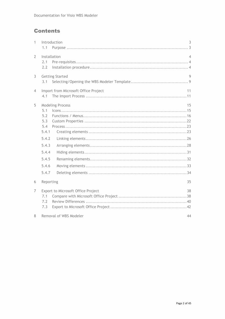
A WBS structure is a hierarchical representation of the elements and sub-elements in a
project (see Figure 1).
Level 1
Level 2
Figure 1: Work Breakdown Structure (WBS) example
The WBS Modeler can either be used to visualize and edit an existing project plan or to cre-
ate a new project plan in Microsoft Office Visio 2007 Professional and then export it to Mi-
crosoft Office Project (2003+) to carry out the next planning steps.
The Application enables effective integration of Visio with Microsoft Office Project. It pro-
vides an approach to visually and graphically create, edit and modify project plans using
Visio.
The WBS Modeler offers the ability to manage project elements in a graphical view, as well
as offering functionality to layout a WBS in Visio. The WBS can be exported back to Micro-
soft Office Project into a new project plan. It is also possible to update an existing plan.
To organize the structure within a WBS Modeler the outline code from Microsoft Office Pro-
ject is utilised.
2 Installation
2.1 Pre-requisites
Microsoft Office Visio 2007 Professional
Microsoft Office Project 2003 SP1 or later
.NET Framework 2.0
http://www.microsoft.com/downloads/details.aspx?FamilyID=0856EACB-4362-4B0D-8EDD-
AAB15C5E04F5&displaylang=en
Microsoft Visio 2007 Primary Interop Assemblies
http://www.microsoft.com/downloads/details.aspx?familyid=59daebaa-bed4-4282-a28c-
b864d8bfa513&displaylang=en
2.2 Installation procedure
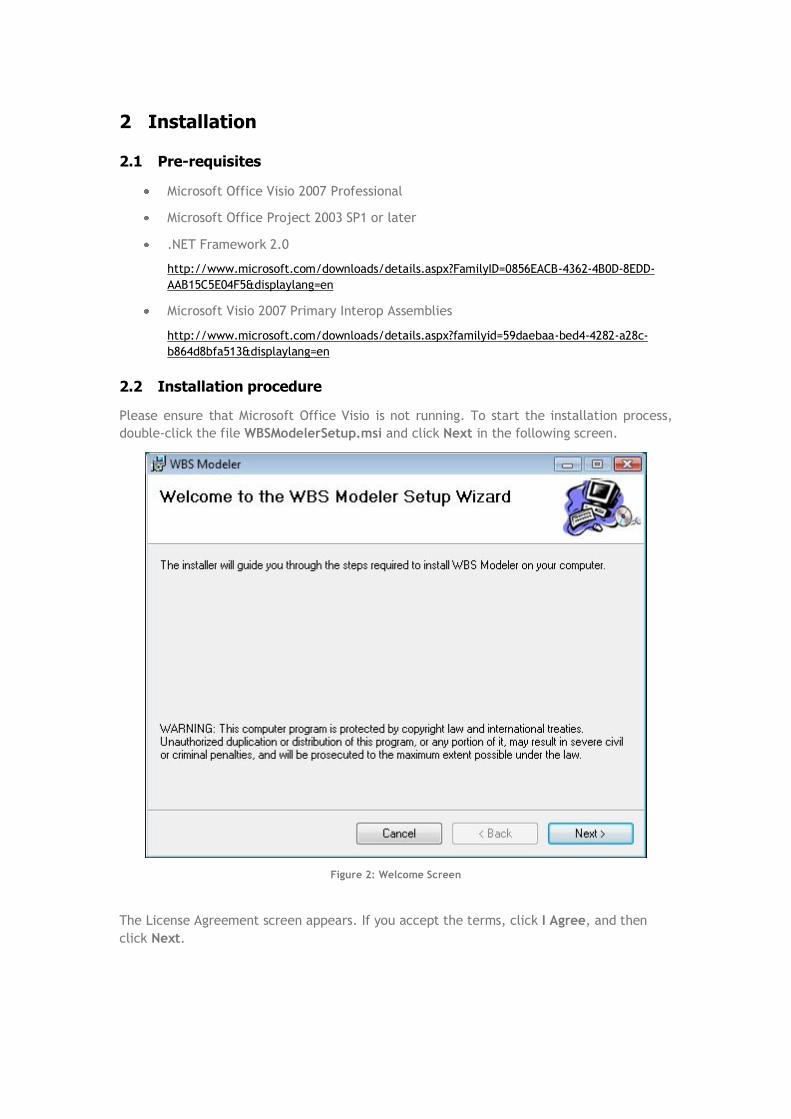
Please ensure that Microsoft Office Visio is not running. To start the installation process,
double-click the file WBSModelerSetup.msi and click Next in the following screen.
Figure 2: Welcome Screen
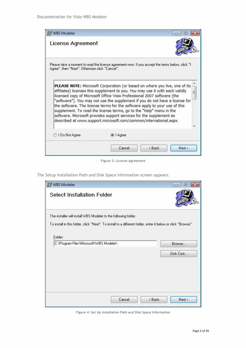
The License Agreement screen appears. If you accept the terms, click I Agree, and then
click Next.
Documentation for Visio WBS Modeler
Page 5 of 45
Figure 3: License Agreement
The Setup Installation Path and Disk Space Information screen appears.
Figure 4: Set Up Installation Path and Disk Space Information
Documentation for Visio WBS Modeler
Page 6 of 45
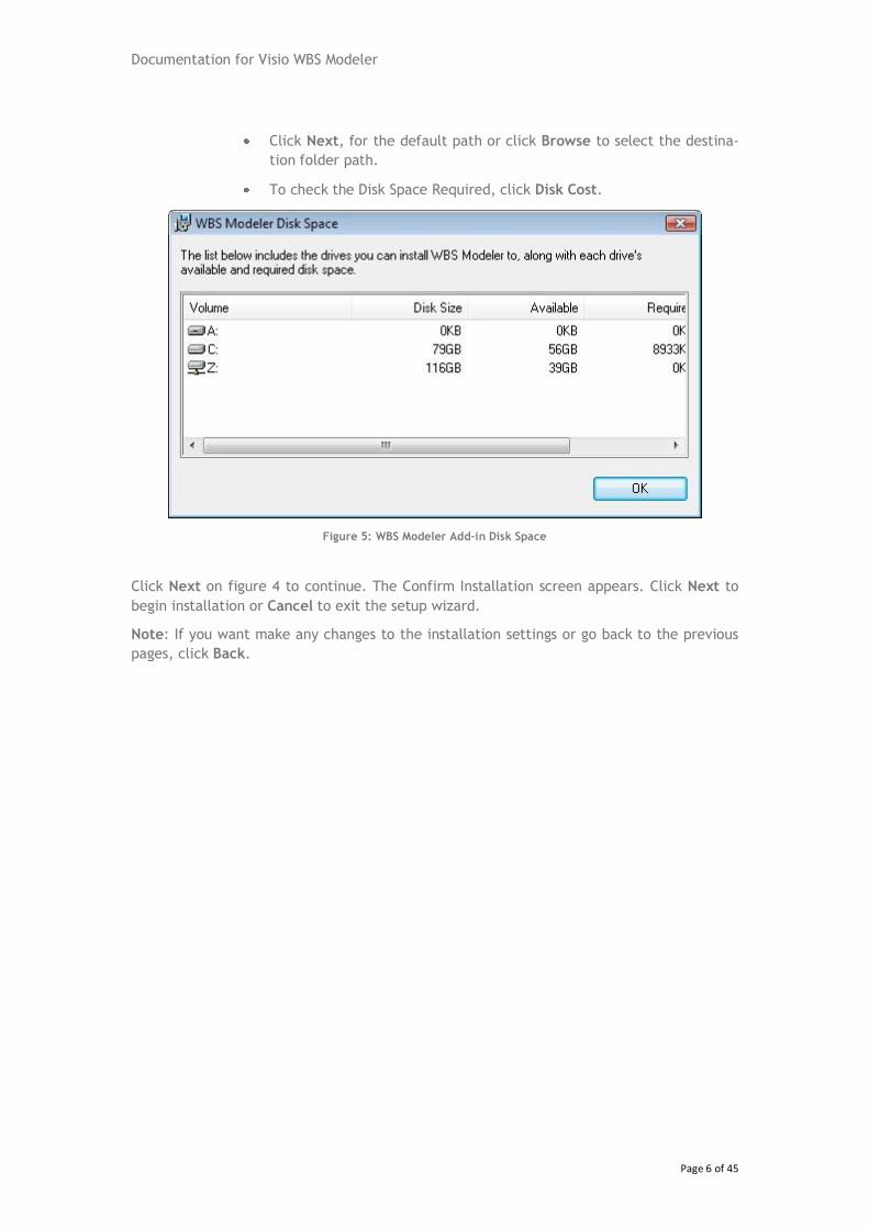
Click Next, for the default path or click Browse to select the destina-
tion folder path.
To check the Disk Space Required, click Disk Cost.
Figure 5: WBS Modeler Add-in Disk Space
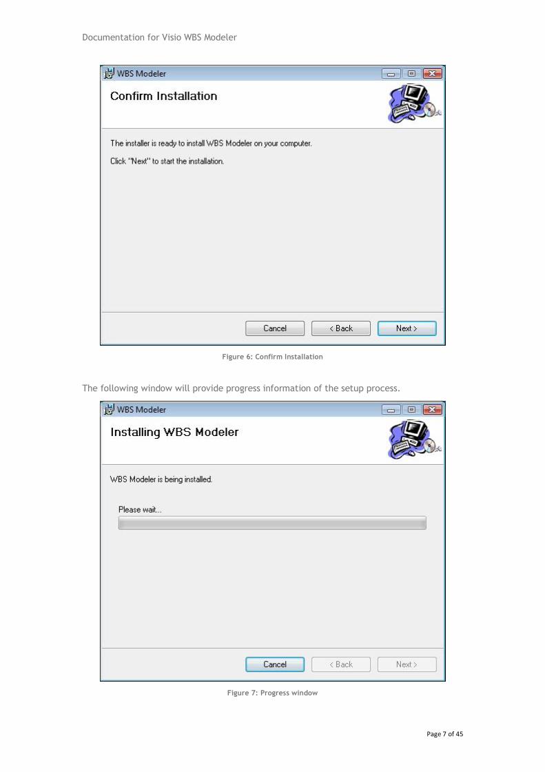
Click Next on figure 4 to continue. The Confirm Installation screen appears. Click Next to
begin installation or Cancel to exit the setup wizard.
Note: If you want make any changes to the installation settings or go back to the previous
pages, click Back.
Documentation for Visio WBS Modeler
Page 7 of 45
Figure 6: Confirm Installation
The following window will provide progress information of the setup process.
Figure 7: Progress window
Documentation for Visio WBS Modeler
Page 8 of 45
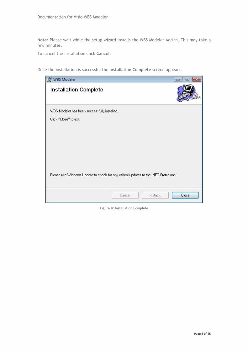
Note: Please wait while the setup wizard installs the WBS Modeler Add-in. This may take a
few minutes.
To cancel the installation click Cancel.
Once the installation is successful the Installation Complete screen appears.
Figure 8: Installation Complete
Documentation for Visio WBS Modeler
Page 9 of 45
3 Getting Started
1. This section describes the basic flow of the reference implementation.
2. The Microsoft Office Visio 2007 Add-in for WBS Modeler is a COM Add-In that starts
up automatically with Visio.
3.1 Selecting/Opening the WBS Modeler Template
The Add-In when installed adds a new template WBS Modeler under WBS Templates Cate-
gory.
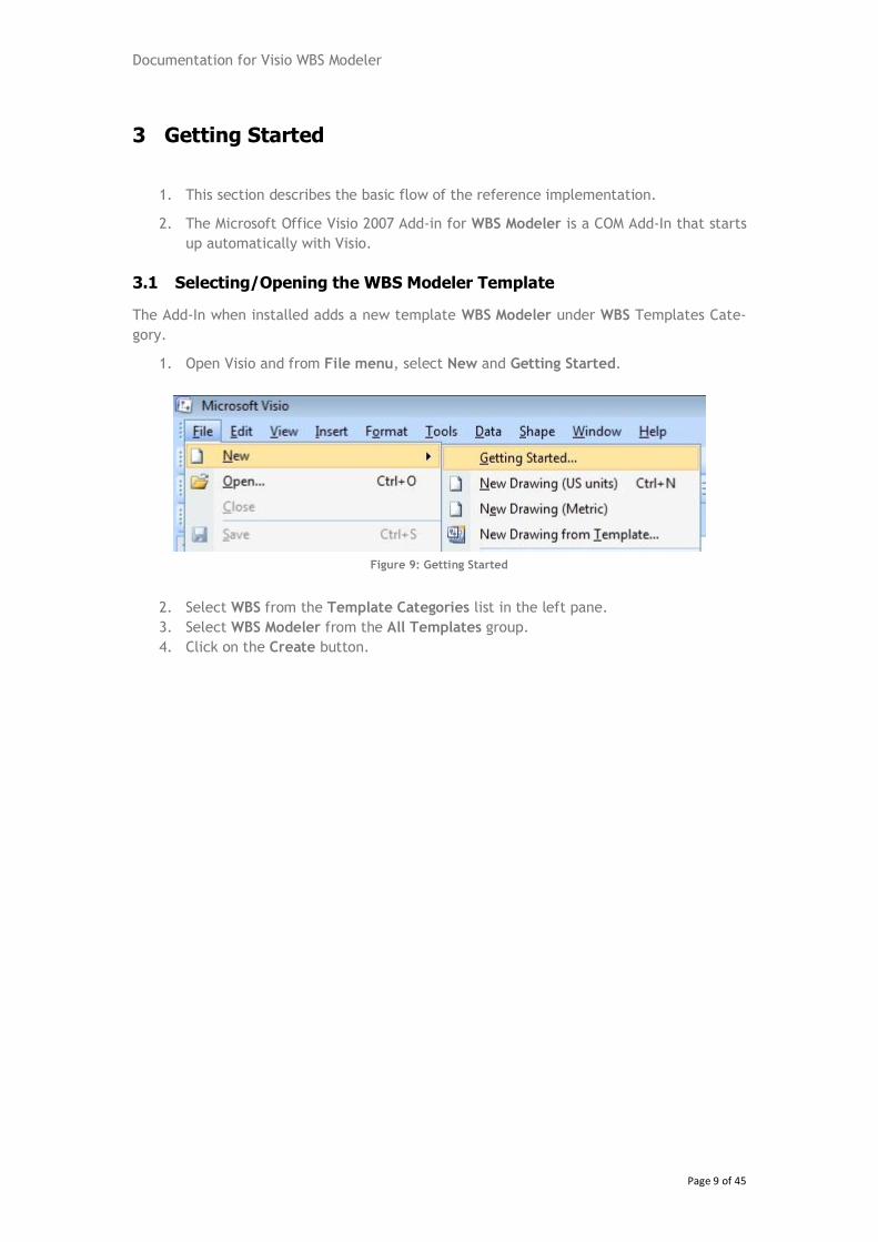
1. Open Visio and from File menu, select New and Getting Started.
Figure 9: Getting Started
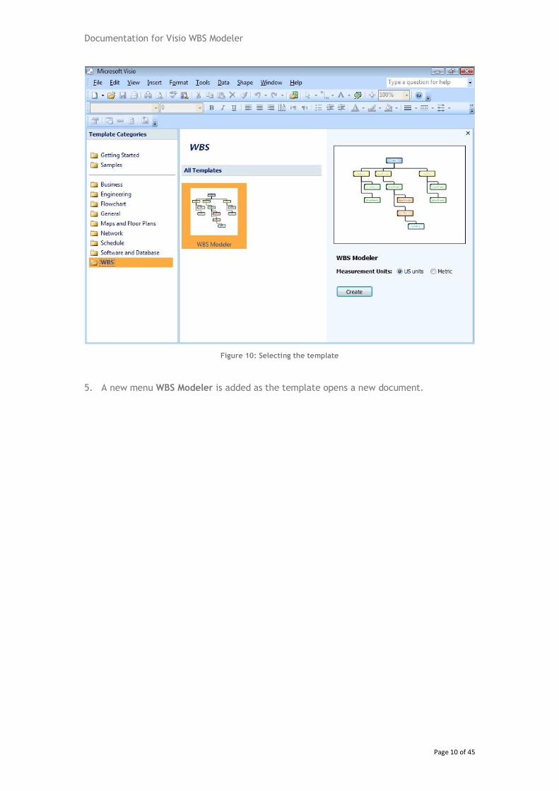
2. Select WBS from the Template Categories list in the left pane.
3. Select WBS Modeler from the All Templates group.
4. Click on the Create button.
Documentation for Visio WBS Modeler
Page 10 of 45
Figure 10: Selecting the template
5. A new menu WBS Modeler is added as the template opens a new document.
Documentation for Visio WBS Modeler
Page 11 of 45
4 Import from Microsoft Office Project
4.1 The Import Process
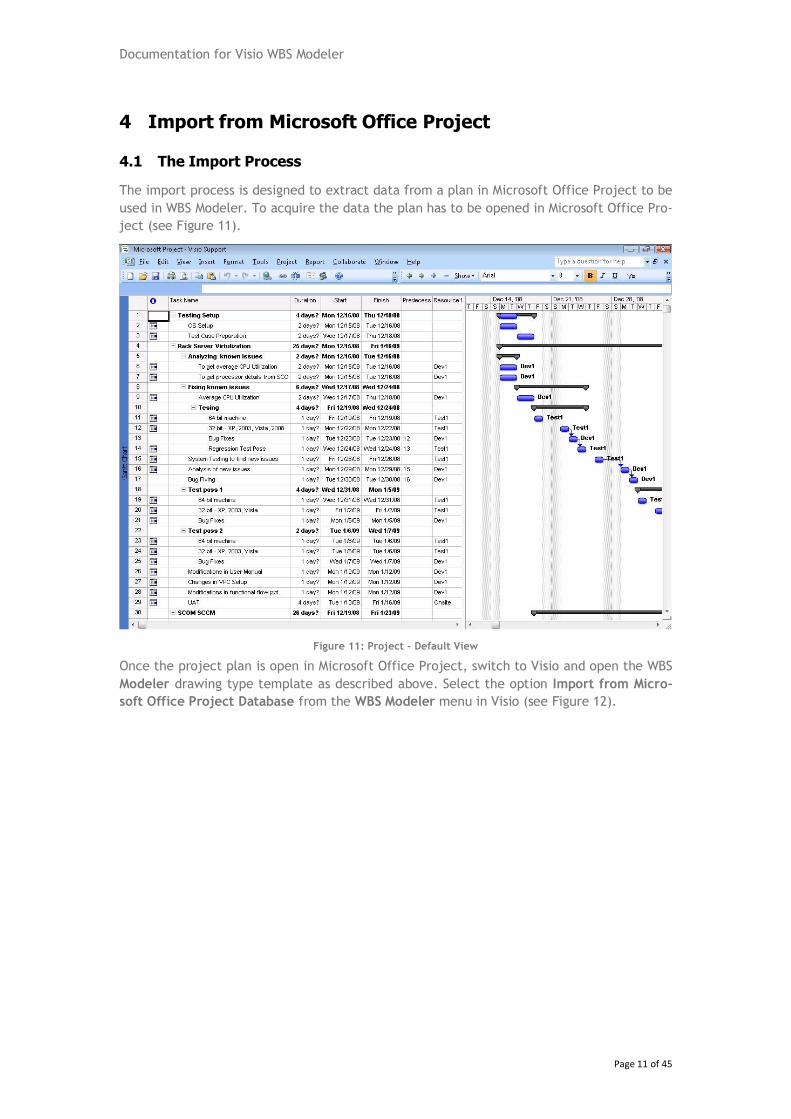
The import process is designed to extract data from a plan in Microsoft Office Project to be
used in WBS Modeler. To acquire the data the plan has to be opened in Microsoft Office Pro-
ject (see Figure 11).
Figure 11: Project - Default View
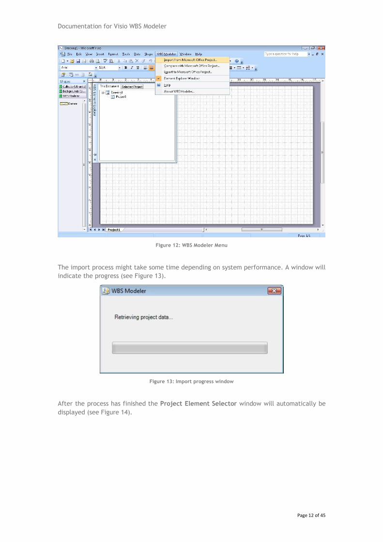
Once the project plan is open in Microsoft Office Project, switch to Visio and open the WBS
Modeler drawing type template as described above. Select the option Import from Micro-
soft Office Project Database from the WBS Modeler menu in Visio (see Figure 12).
Documentation for Visio WBS Modeler
Page 12 of 45
Figure 12: WBS Modeler Menu
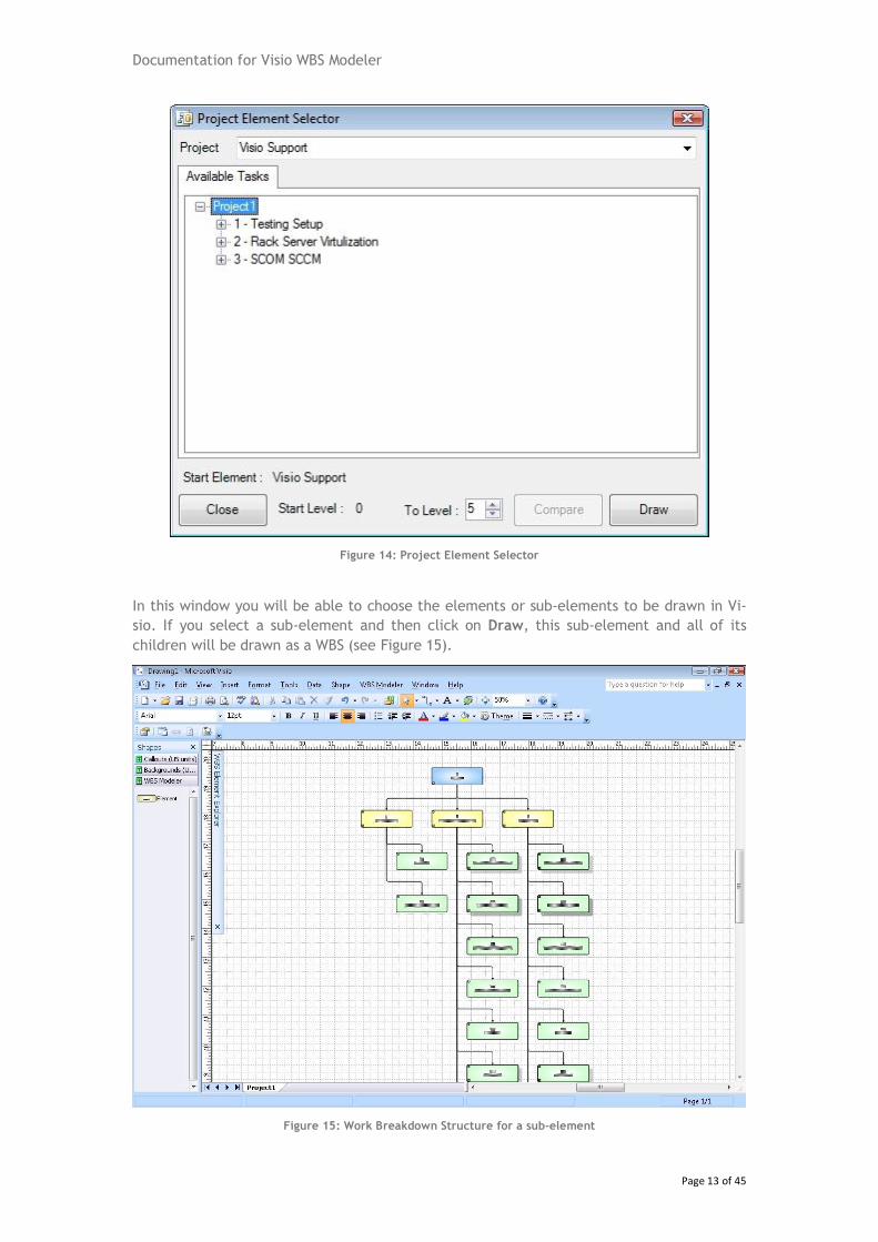
The import process might take some time depending on system performance. A window will
indicate the progress (see Figure 13).
Figure 13: Import progress window
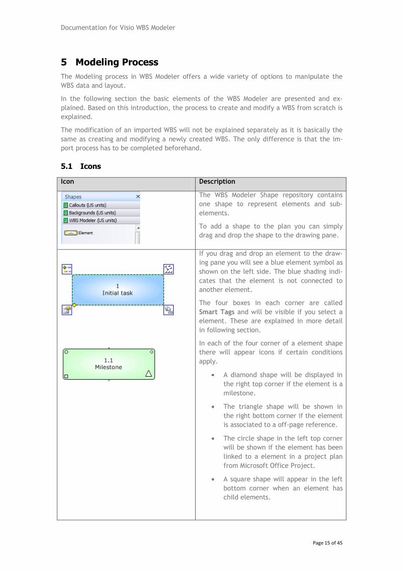
After the process has finished the Project Element Selector window will automatically be
displayed (see Figure 14).
Documentation for Visio WBS Modeler
Page 13 of 45
Figure 14: Project Element Selector
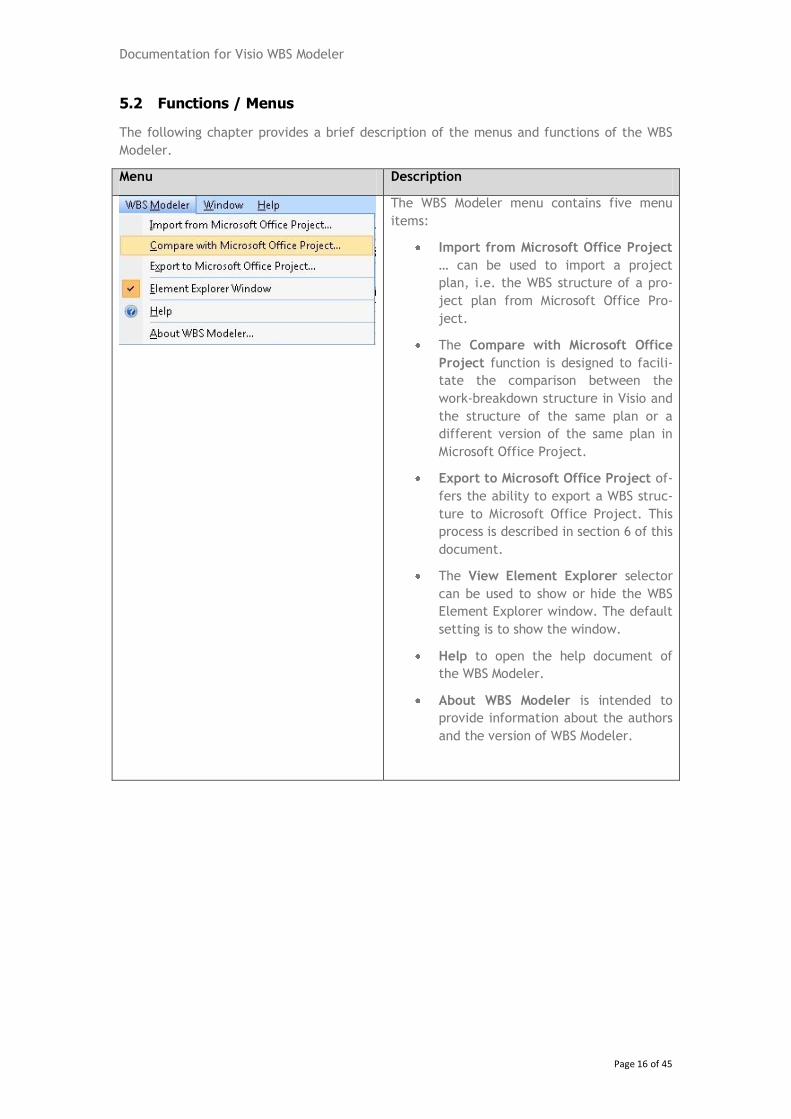
In this window you will be able to choose the elements or sub-elements to be drawn in Vi-
sio. If you select a sub-element and then click on Draw, this sub-element and all of its
children will be drawn as a WBS (see Figure 15).
Figure 15: Work Breakdown Structure for a sub-element

Documentation for Visio WBS Modeler
Page 14 of 45
The same applies if you choose to import the project summary element; the resulting WBS
will in most cases be considerably bigger and due to limitations in the layout process not
aligned as in the previous example. However, the layout can easily be improved using the
functionality provided by WBS Modeler as described in the Modeling section later in this
document.
Documentation for Visio WBS Modeler
Page 15 of 45
5 Modeling Process
The Modeling process in WBS Modeler offers a wide variety of options to manipulate the
WBS data and layout.
In the following section the basic elements of the WBS Modeler are presented and ex-
plained. Based on this introduction, the process to create and modify a WBS from scratch is
explained.
The modification of an imported WBS will not be explained separately as it is basically the
same as creating and modifying a newly created WBS. The only difference is that the im-
port process has to be completed beforehand.
5.1 Icons
Icon Description
The WBS Modeler Shape repository contains
one shape to represent elements and sub-
elements.
To add a shape to the plan you can simply
drag and drop the shape to the drawing pane.
If you drag and drop an element to the draw-
ing pane you will see a blue element symbol as
shown on the left side. The blue shading indi-
cates that the element is not connected to
another element.
The four boxes in each corner are called
Smart Tags and will be visible if you select a
element. These are explained in more detail
in following section.
In each of the four corner of a element shape
there will appear icons if certain conditions
apply.
A diamond shape will be displayed in
the right top corner if the element is a
milestone.
The triangle shape will be shown in
the right bottom corner if the element
is associated to a off-page reference.
The circle shape in the left top corner
will be shown if the element has been
linked to a element in a project plan
from Microsoft Office Project.
A square shape will appear in the left
bottom corner when an element has
child elements.
Documentation for Visio WBS Modeler
Page 16 of 45
5.2 Functions / Menus
The following chapter provides a brief description of the menus and functions of the WBS
Modeler.
Menu Description
The WBS Modeler menu contains five menu
items:
Import from Microsoft Office Project
… can be used to import a project
plan, i.e. the WBS structure of a pro-
ject plan from Microsoft Office Pro-
ject.
The Compare with Microsoft Office
Project function is designed to facili-
tate the comparison between the
work-breakdown structure in Visio and
the structure of the same plan or a
different version of the same plan in
Microsoft Office Project.
Export to Microsoft Office Project of-
fers the ability to export a WBS struc-
ture to Microsoft Office Project. This
process is described in section 6 of this
document.
The View Element Explorer selector
can be used to show or hide the WBS
Element Explorer window. The default
setting is to show the window.
Help to open the help document of
the WBS Modeler.
About WBS Modeler is intended to
provide information about the authors
and the version of WBS Modeler.
Documentation for Visio WBS Modeler
Page 17 of 45
Menu Description
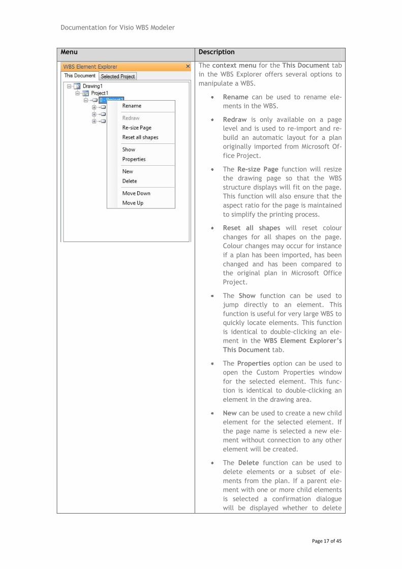
The context menu for the This Document tab
in the WBS Explorer offers several options to
manipulate a WBS.
Rename can be used to rename ele-
ments in the WBS.
Redraw is only available on a page
level and is used to re-import and re-
build an automatic layout for a plan
originally imported from Microsoft Of-
fice Project.
The Re-size Page function will resize
the drawing page so that the WBS
structure displays will fit on the page.
This function will also ensure that the
aspect ratio for the page is maintained
to simplify the printing process.
Reset all shapes will reset colour
changes for all shapes on the page.
Colour changes may occur for instance
if a plan has been imported, has been
changed and has been compared to
the original plan in Microsoft Office
Project.
The Show function can be used to
jump directly to an element. This
function is useful for very large WBS to
quickly locate elements. This function
is identical to double-clicking an ele-
ment in the WBS Element Explorer’s
This Document tab.
The Properties option can be used to
open the Custom Properties window
for the selected element. This func-
tion is identical to double-clicking an
element in the drawing area.
New can be used to create a new child
element for the selected element. If
the page name is selected a new ele-
ment without connection to any other
element will be created.
The Delete function can be used to
delete elements or a subset of ele-
ments from the plan. If a parent ele-
ment with one or more child elements
is selected a confirmation dialogue
will be displayed whether to delete
Documentation for Visio WBS Modeler
Page 18 of 45
Menu Description
the child elements as well or not. If
the child elements are kept they will
be connected to the parent element of
the deleted element if present.
Move Down / Move Up can be used to
move an element up or down within
the currently selected WBS level.
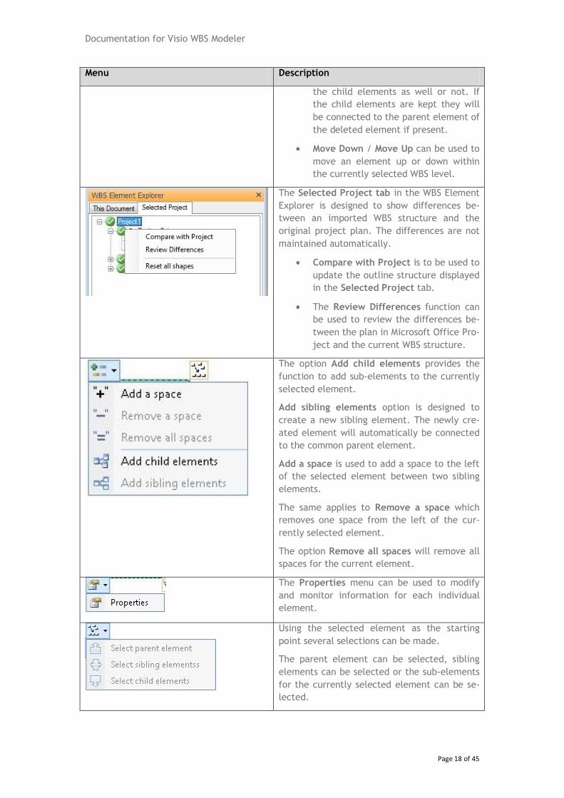
The Selected Project tab in the WBS Element
Explorer is designed to show differences be-
tween an imported WBS structure and the
original project plan. The differences are not
maintained automatically.
Compare with Project is to be used to
update the outline structure displayed
in the Selected Project tab.
The Review Differences function can
be used to review the differences be-
tween the plan in Microsoft Office Pro-
ject and the current WBS structure.
The option Add child elements provides the
function to add sub-elements to the currently
selected element.
Add sibling elements option is designed to
create a new sibling element. The newly cre-
ated element will automatically be connected
to the common parent element.
Add a space is used to add a space to the left
of the selected element between two sibling
elements.
The same applies to Remove a space which
removes one space from the left of the cur-
rently selected element.
The option Remove all spaces will remove all
spaces for the current element.
The Properties menu can be used to modify
and monitor information for each individual
element.
Using the selected element as the starting
point several selections can be made.
The parent element can be selected, sibling
elements can be selected or the sub-elements
for the currently selected element can be se-
lected.
Documentation for Visio WBS Modeler
Page 19 of 45
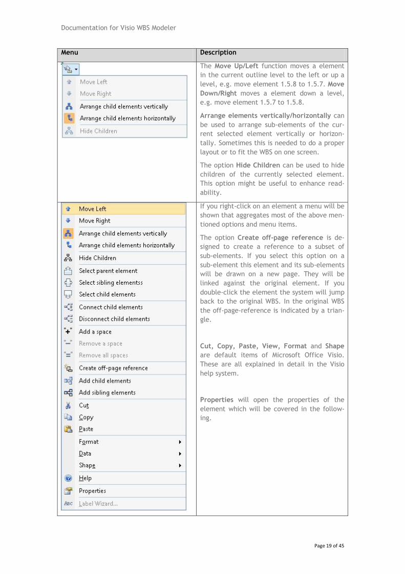
Menu Description
The Move Up/Left function moves a element
in the current outline level to the left or up a
level, e.g. move element 1.5.8 to 1.5.7. Move
Down/Right moves a element down a level,
e.g. move element 1.5.7 to 1.5.8.
Arrange elements vertically/horizontally can
be used to arrange sub-elements of the cur-
rent selected element vertically or horizon-
tally. Sometimes this is needed to do a proper
layout or to fit the WBS on one screen.
The option Hide Children can be used to hide
children of the currently selected element.
This option might be useful to enhance read-
ability.
If you right-click on an element a menu will be
shown that aggregates most of the above men-
tioned options and menu items.
The option Create off-page reference is de-
signed to create a reference to a subset of
sub-elements. If you select this option on a
sub-element this element and its sub-elements
will be drawn on a new page. They will be
linked against the original element. If you
double-click the element the system will jump
back to the original WBS. In the original WBS
the off-page-reference is indicated by a trian-
gle.
Cut, Copy, Paste, View, Format and Shape
are default items of Microsoft Office Visio.
These are all explained in detail in the Visio
help system.
Properties will open the properties of the
element which will be covered in the follow-
ing.
Documentation for Visio WBS Modeler
Page 20 of 45
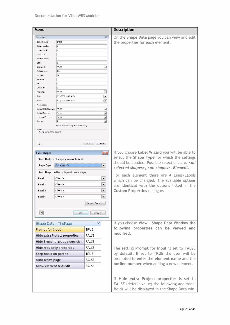
Menu Description
On the Shape Data page you can view and edit
the properties for each element.
If you choose Label Wizard you will be able to
select the Shape Type for which the settings
should be applied. Possible selections are: <all
selected shapes>, <all shapes>, Element.
For each element there are 4 Lines/Labels
which can be changed. The available options
are identical with the options listed in the
Custom Properties dialogue.
If you choose View – Shape Data Window the
following properties can be viewed and
modified.
The setting Prompt for Input is set to FALSE
by default. If set to TRUE the user will be
prompted to enter the element name and the
outline number when adding a new element.
If Hide extra Project properties is set to
FALSE (default value) the following additional
fields will be displayed in the Shape Data win-
Documentation for Visio WBS Modeler
Page 21 of 45
Menu Description
dow:
Cos t
Est im at ed
% C om pl et e
Dur at io n
Res ou rc e
ID
Uni qu e ID
Mil es to ne
Sta rt
Fin is h
Pre de ce ss or
If Hide Element layout properties is set to
FALSE (default setting) the following addi-
tional information will be displayed in the
Shape Data window for elements:
Ver ti ca l Su b Ele me nt
Ver ti ca l Sp ac ing
Hor iz on ta l Sp aci ng
Hid e Ch il dr en
Spa ce s
If Hide read only properties is set to FALSE
(default is TRUE) the following additional
properties will be displayed in the Shape Data
window for elements:
Pag e Na me
Pag e Nu mb er
Fil e Na me
Lab el N am e
Lab el W BS
Documentation for Visio WBS Modeler
Page 22 of 45
Menu Description
The Keep focus on parent is set to TRUE by
default. If this option is set to FALSE the se-
lection will be moved to the child elements
instead of the parent element when connect-
ing elements.
5.3 Custom Properties
Property Description
Element Name Name of the element
Outline Number Position of the element in the WBS/Outline;
The Outline Number represents the level of the element within
the work breakdown structure of the plan. If only a part of the
whole plan is imported from Microsoft Office Project this will
refer to the original structure of the plan.
This information will be used to update the relevant parts of
the project plan when the plan is exported back to Microsoft
Office Project.
WBS Code The WBS Code is used to store information about the original
WBS value of a plan as imported from Microsoft Office Project.
Element Project This field is designed to store information about the project an
element belongs to.
Vertical Sub Elements Child elements associated with this element will be arranged
vertically if set to TRUE (default). If set to FALSE child ele-
ments will be arranged horizontally.
Vertical Spacing This option will affect all direct child elements of the currently
selected element. The options available are:
Tightest, tight, normal, loose,
loosest.
Horizontal Spacing This option will affect all direct child elements of the currently
selected element. The options available are:
tightest, tight, normal, loose,
loosest.
Hide Children If set to TRUE all children of the currently selected element
will be hidden. If set to FALSE hidden elements will be visible
again.
Spaces Determines the spaces left to or above the currently selected
element depending on the parent element’s Vertical Sub Ele-
ment setting.
Documentation for Visio WBS Modeler
Page 23 of 45
Page Name Read-Only field for the name of the page the element is cur-
rently being displayed in.
Page Number Read-Only field for the number of the page the element is cur-
rently being displayed in.
File Name Read-only field to display the Visio file name.
Label Name Read-only field for the element name as the display area length
is limited to 24 characters.
Label WBS Read-only field to display the element label for the WBS Code.
If the WBS code is different from the Outline number it will be
displayed as: “1.2.5 [1.2.6]” where the first number represents
the Outline Number and the number in brackets represents the
WBS Code as originally read from Microsoft Office Project.
5.4 Process
This chapter covers the functionality of the WBS Modeler and how the functions and menu
items briefly described in the previous two sections can be used.
5.4.1 Creating elements
5.4.1.1 Drag and drop
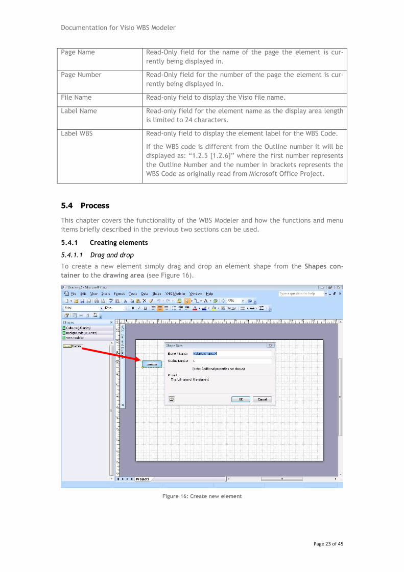
To create a new element simply drag and drop an element shape from the Shapes con-
tainer to the drawing area (see Figure 16).
Figure 16: Create new element
Documentation for Visio WBS Modeler
Page 24 of 45
The prompt for the Element Name and Outline Number will open automatically after the
element has been dropped to drawing area. The Outline Number will be recalculated once
the element has been connected to another element to achieve consistency.
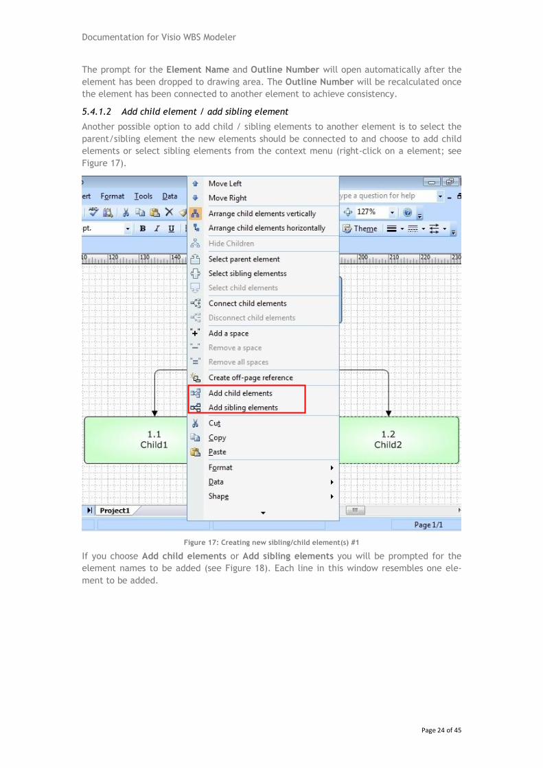
5.4.1.2 Add child element / add sibling element
Another possible option to add child / sibling elements to another element is to select the
parent/sibling element the new elements should be connected to and choose to add child
elements or select sibling elements from the context menu (right-click on a element; see
Figure 17).
Figure 17: Creating new sibling/child element(s) #1
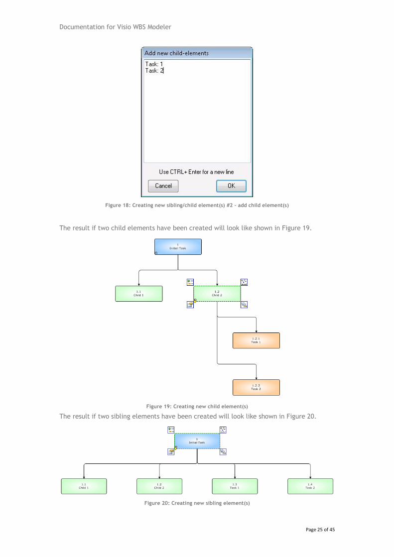
If you choose Add child elements or Add sibling elements you will be prompted for the
element names to be added (see Figure 18). Each line in this window resembles one ele-
ment to be added.
Documentation for Visio WBS Modeler
Page 25 of 45
Figure 18: Creating new sibling/child element(s) #2 – add child element(s)
The result if two child elements have been created will look like shown in Figure 19.
Figure 19: Creating new child element(s)
The result if two sibling elements have been created will look like shown in Figure 20.
Figure 20: Creating new sibling element(s)
Documentation for Visio WBS Modeler
Page 26 of 45
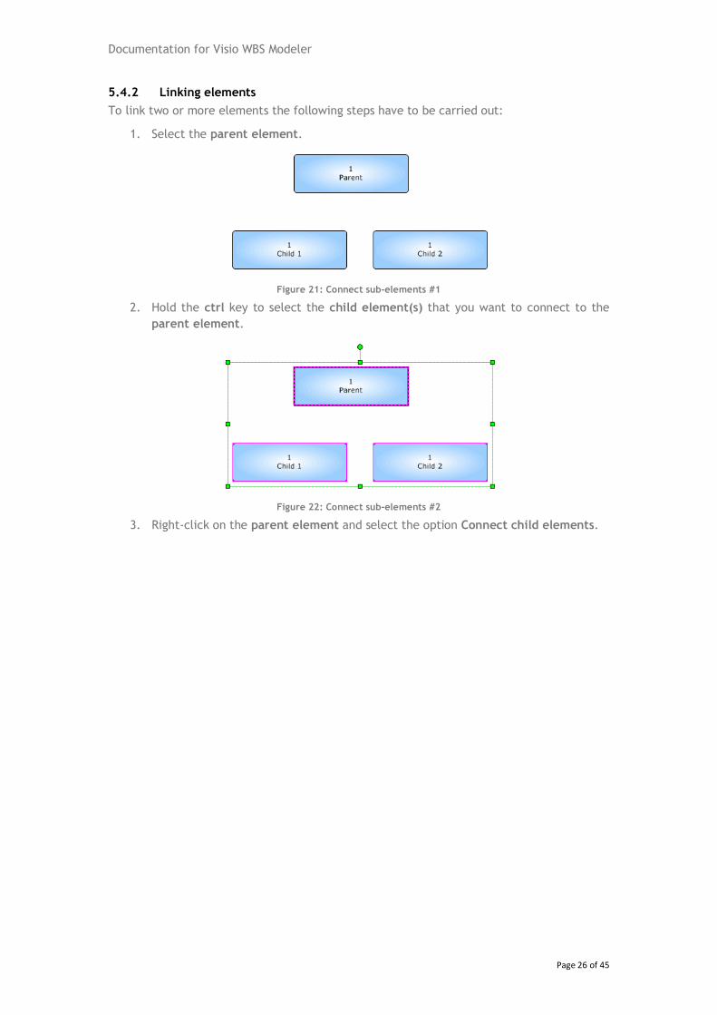
5.4.2 Linking elements
To link two or more elements the following steps have to be carried out:
1. Select the parent element.
Figure 21: Connect sub-elements #1
2. Hold the ctrl key to select the child element(s) that you want to connect to the
parent element.
Figure 22: Connect sub-elements #2
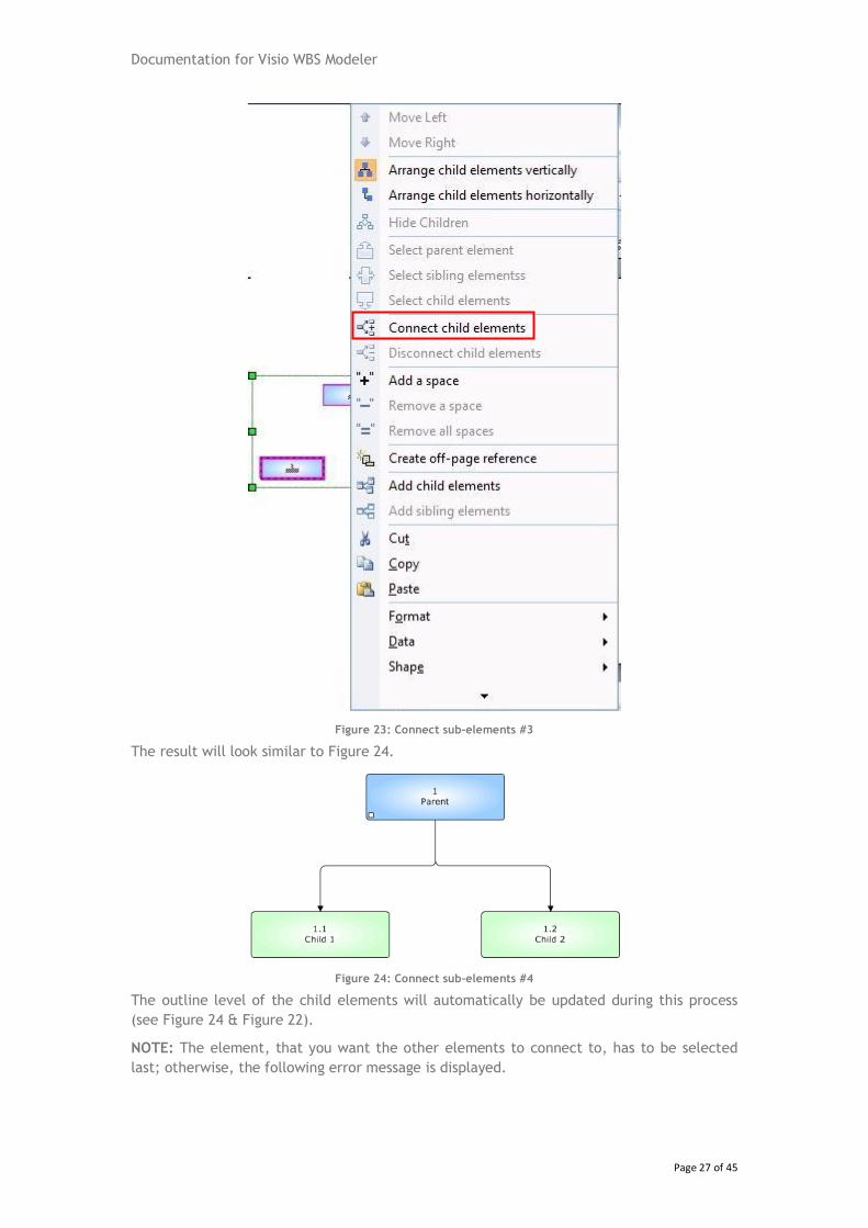
3. Right-click on the parent element and select the option Connect child elements.
Documentation for Visio WBS Modeler
Page 27 of 45
Figure 23: Connect sub-elements #3
The result will look similar to Figure 24.
Figure 24: Connect sub-elements #4
The outline level of the child elements will automatically be updated during this process
(see Figure 24 & Figure 22).
NOTE: The element, that you want the other elements to connect to, has to be selected
last; otherwise, the following error message is displayed.
Documentation for Visio WBS Modeler
Page 28 of 45
Figure 25: Error message - Task can only have one parent
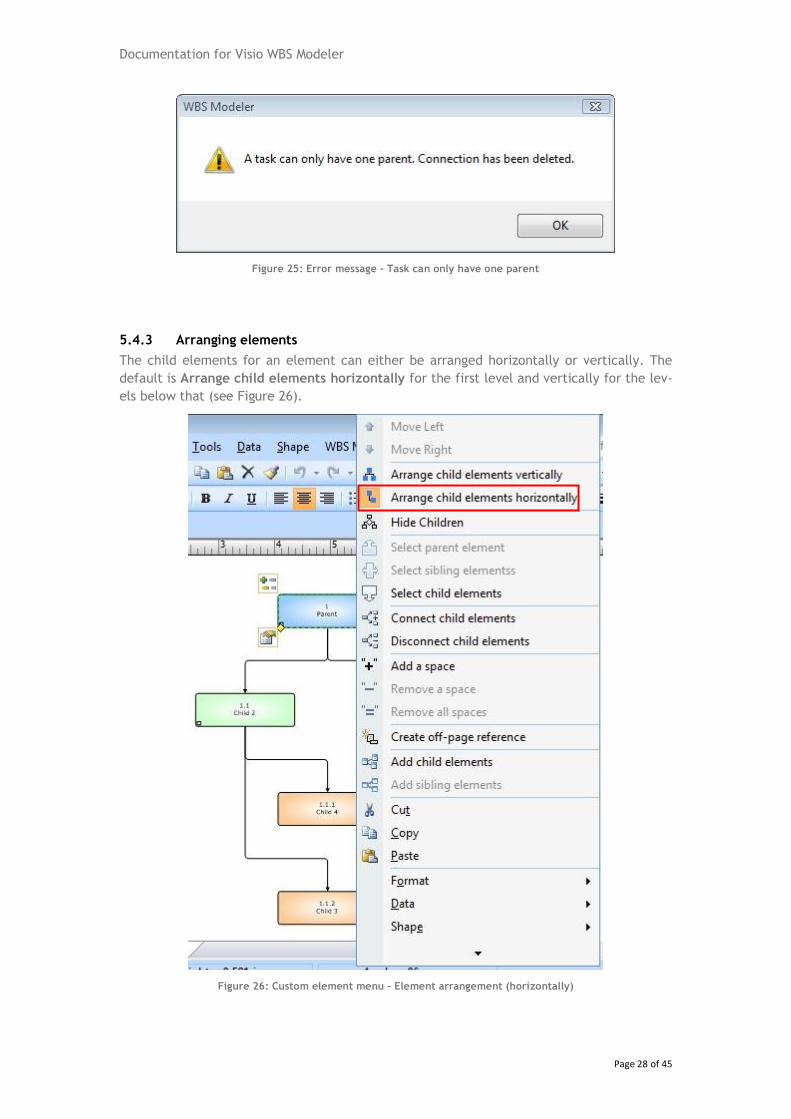
5.4.3 Arranging elements
The child elements for an element can either be arranged horizontally or vertically. The
default is Arrange child elements horizontally for the first level and vertically for the lev-
els below that (see Figure 26).
Figure 26: Custom element menu – Element arrangement (horizontally)
Documentation for Visio WBS Modeler
Page 29 of 45
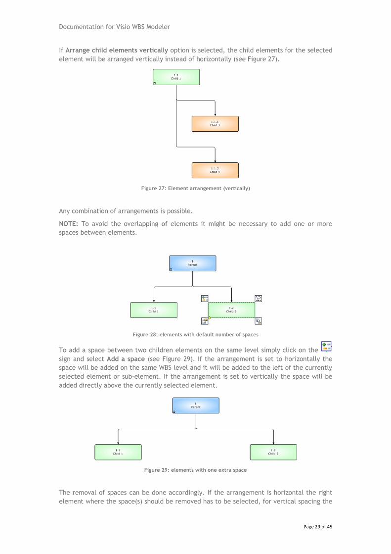
If Arrange child elements vertically option is selected, the child elements for the selected
element will be arranged vertically instead of horizontally (see Figure 27).
Figure 27: Element arrangement (vertically)
Any combination of arrangements is possible.
NOTE: To avoid the overlapping of elements it might be necessary to add one or more
spaces between elements.
Figure 28: elements with default number of spaces
To add a space between two children elements on the same level simply click on the
sign and select Add a space (see Figure 29). If the arrangement is set to horizontally the
space will be added on the same WBS level and it will be added to the left of the currently
selected element or sub-element. If the arrangement is set to vertically the space will be
added directly above the currently selected element.
Figure 29: elements with one extra space
The removal of spaces can be done accordingly. If the arrangement is horizontal the right
element where the space(s) should be removed has to be selected, for vertical spacing the
Documentation for Visio WBS Modeler
Page 30 of 45
elements directly below the spaces have to be selected. If Remove a space is selected one
space will be removed at a time. The Remove all spaces option can be used to remove
more than one space between two elements.
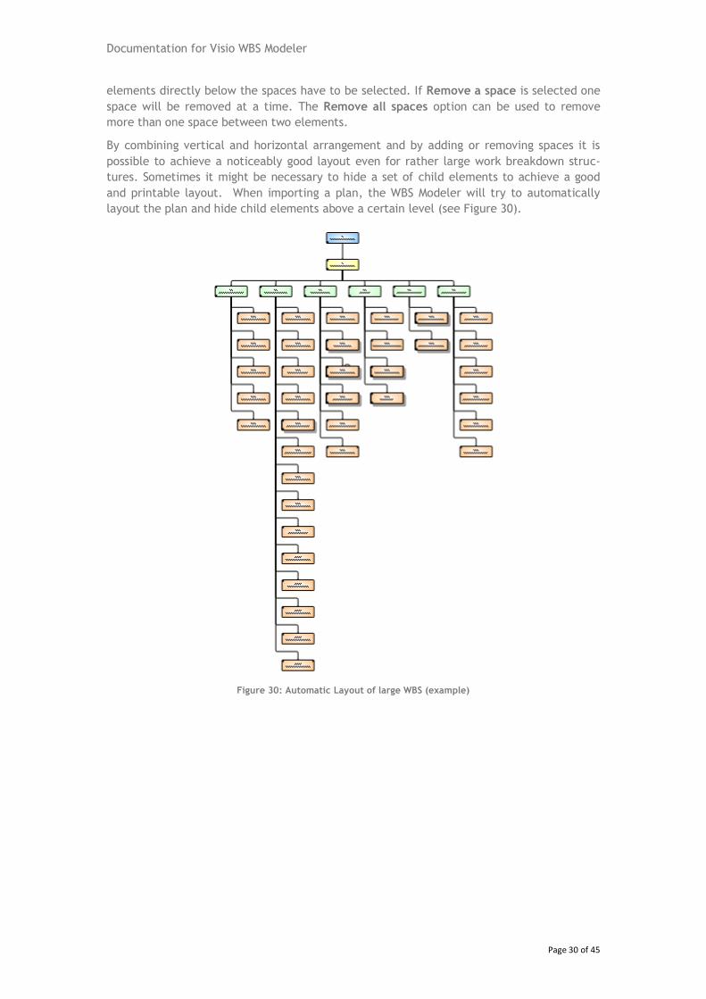
By combining vertical and horizontal arrangement and by adding or removing spaces it is
possible to achieve a noticeably good layout even for rather large work breakdown struc-
tures. Sometimes it might be necessary to hide a set of child elements to achieve a good
and printable layout. When importing a plan, the WBS Modeler will try to automatically
layout the plan and hide child elements above a certain level (see Figure 30).
Figure 30: Automatic Layout of large WBS (example)
Documentation for Visio WBS Modeler
Page 31 of 45
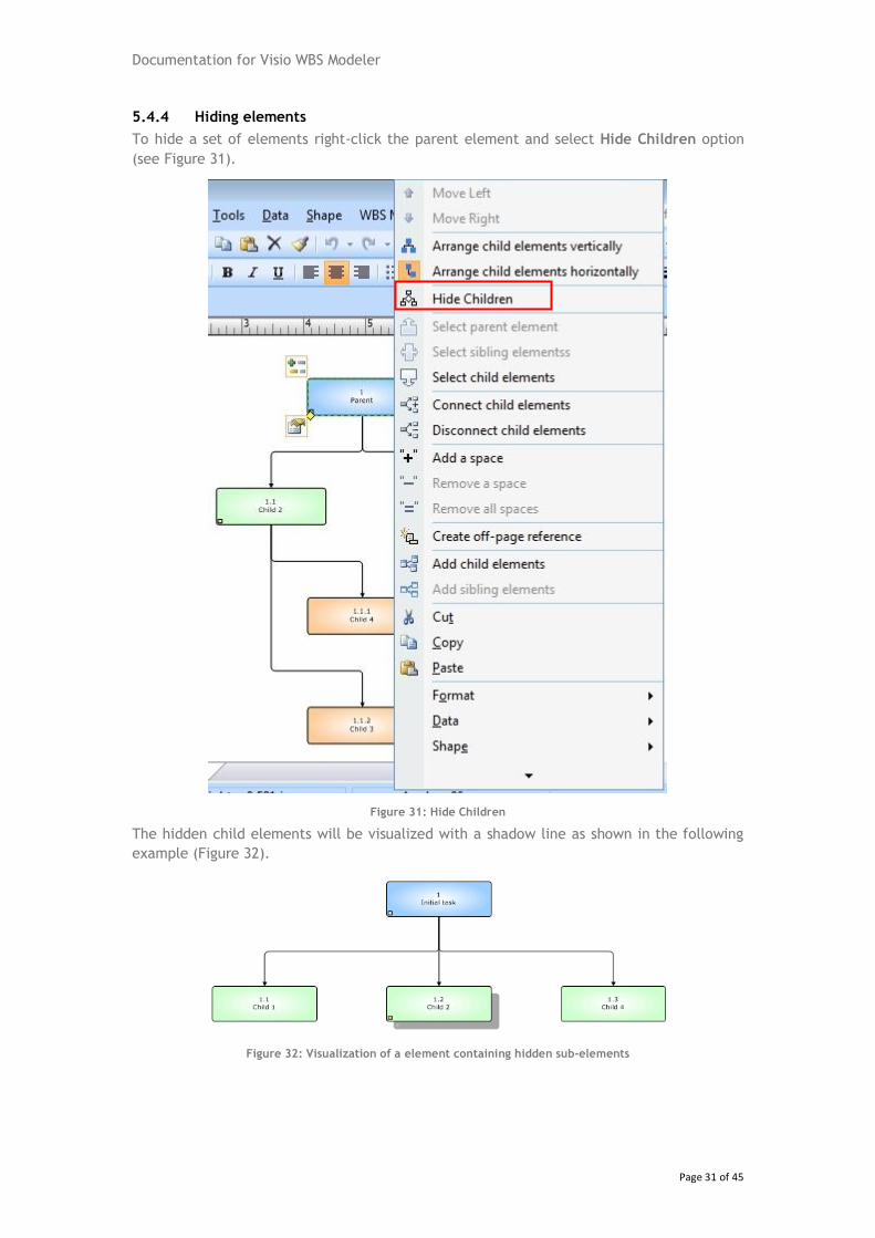
5.4.4 Hiding elements
To hide a set of elements right-click the parent element and select Hide Children option
(see Figure 31).
Figure 31: Hide Children
The hidden child elements will be visualized with a shadow line as shown in the following
example (Figure 32).
Figure 32: Visualization of a element containing hidden sub-elements
Documentation for Visio WBS Modeler
Page 32 of 45
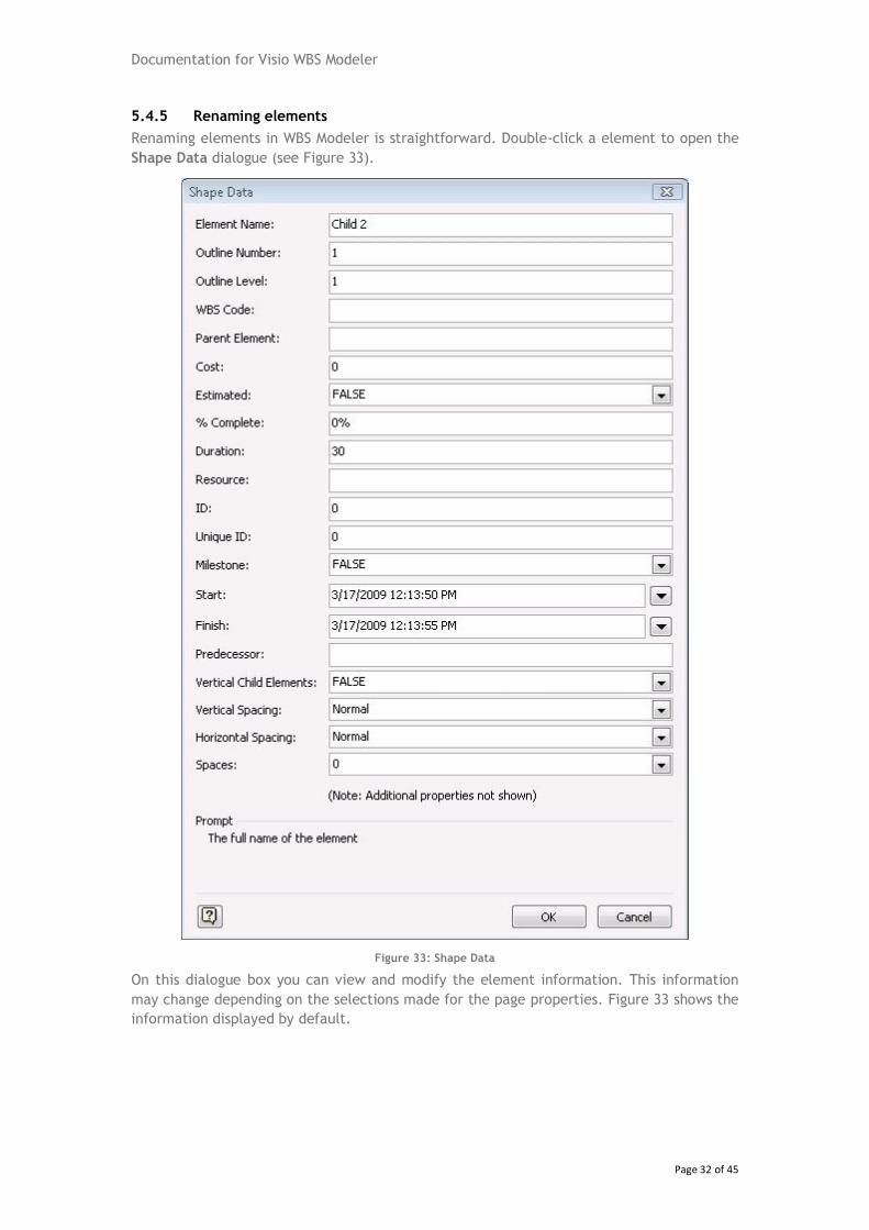
5.4.5 Renaming elements
Renaming elements in WBS Modeler is straightforward. Double-click a element to open the
Shape Data dialogue (see Figure 33).
Figure 33: Shape Data
On this dialogue box you can view and modify the element information. This information
may change depending on the selections made for the page properties. Figure 33 shows the
information displayed by default.
Documentation for Visio WBS Modeler
Page 33 of 45
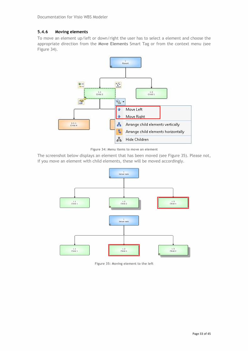
5.4.6 Moving elements
To move an element up/left or down/right the user has to select a element and choose the
appropriate direction from the Move Elements Smart Tag or from the context menu (see
Figure 34).
Figure 34: Menu items to move an element
The screenshot below displays an element that has been moved (see Figure 35). Please not,
if you move an element with child elements, these will be moved accordingly.
Figure 35: Moving element to the left
Documentation for Visio WBS Modeler
Page 34 of 45
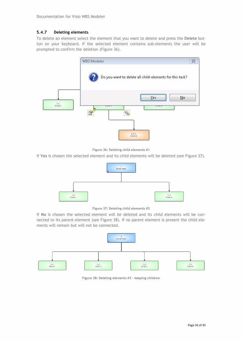
5.4.7 Deleting elements
To delete an element select the element that you want to delete and press the Delete but-
ton on your keyboard. If the selected element contains sub-elements the user will be
prompted to confirm the deletion (Figure 36).
Figure 36: Deleting child elements #1
If Yes is chosen the selected element and its child elements will be deleted (see Figure 37).
Figure 37: Deleting child elements #2
If No is chosen the selected element will be deleted and its child elements will be con-
nected to its parent-element (see Figure 38). If no parent element is present the child ele-
ments will remain but will not be connected.
Figure 38: Deleting elements #3 - keeping children
Documentation for Visio WBS Modeler
Page 35 of 45
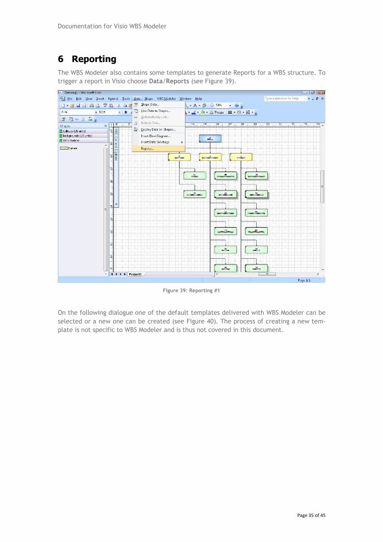
6 Reporting
The WBS Modeler also contains some templates to generate Reports for a WBS structure. To
trigger a report in Visio choose Data/Reports (see Figure 39).
Figure 39: Reporting #1
On the following dialogue one of the default templates delivered with WBS Modeler can be
selected or a new one can be created (see Figure 40). The process of creating a new tem-
plate is not specific to WBS Modeler and is thus not covered in this document.
Documentation for Visio WBS Modeler
Page 36 of 45
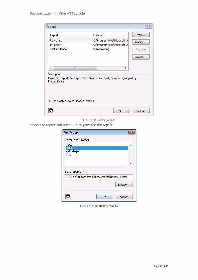
Figure 40: Choose Report
Select the report and press Run to generate the report.
Figure 41: Run Report window
Documentation for Visio WBS Modeler
Page 37 of 45
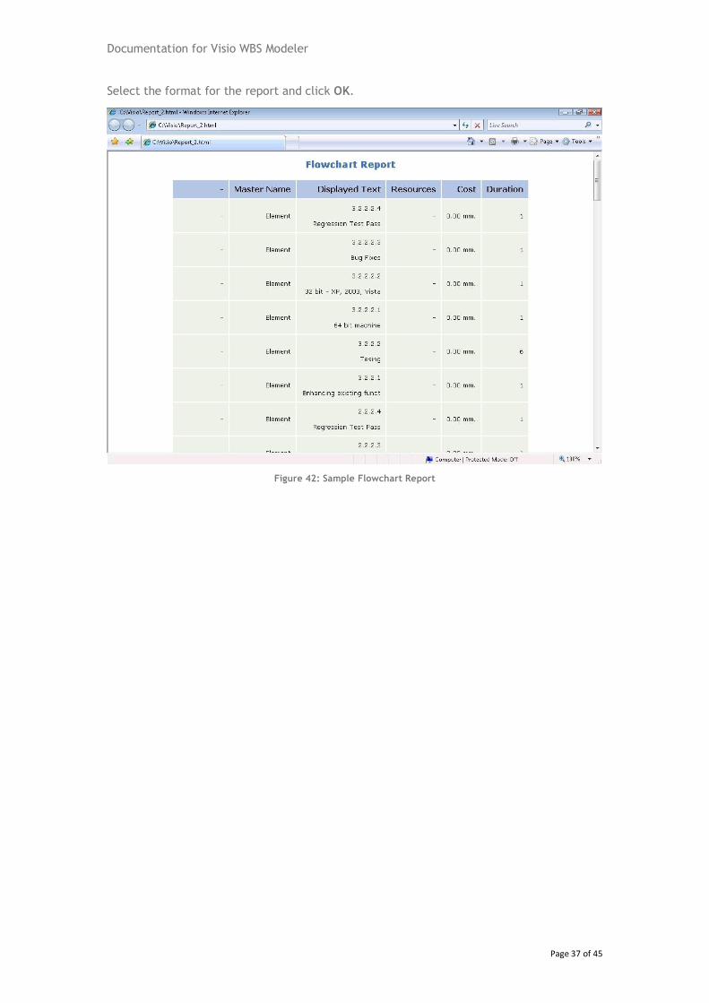
Select the format for the report and click OK.
Figure 42: Sample Flowchart Report
Documentation for Visio WBS Modeler
Page 38 of 45
7 Export to Microsoft Office Project
7.1 Compare with Microsoft Office Project
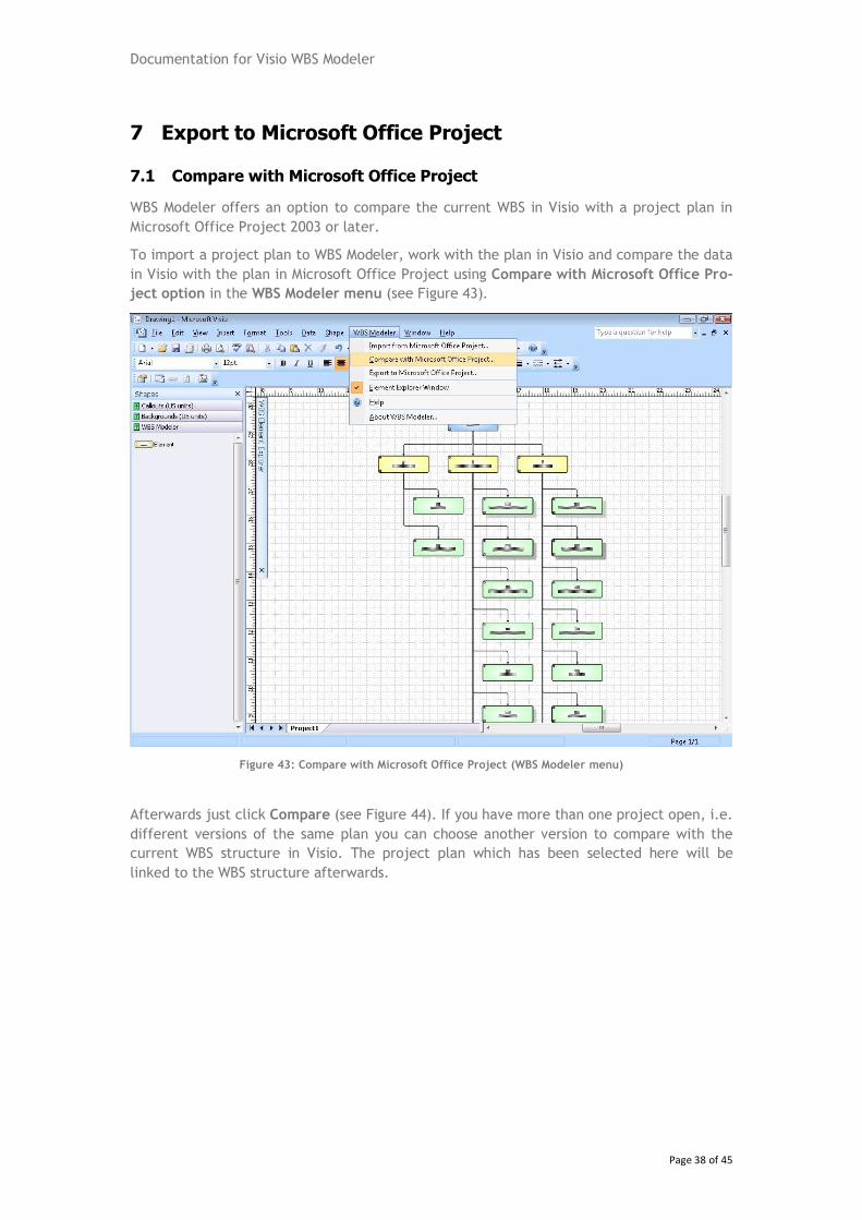
WBS Modeler offers an option to compare the current WBS in Visio with a project plan in
Microsoft Office Project 2003 or later.
To import a project plan to WBS Modeler, work with the plan in Visio and compare the data
in Visio with the plan in Microsoft Office Project using Compare with Microsoft Office Pro-
ject option in the WBS Modeler menu (see Figure 43).
Figure 43: Compare with Microsoft Office Project (WBS Modeler menu)
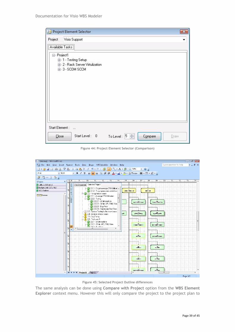
Afterwards just click Compare (see Figure 44). If you have more than one project open, i.e.
different versions of the same plan you can choose another version to compare with the
current WBS structure in Visio. The project plan which has been selected here will be
linked to the WBS structure afterwards.
Documentation for Visio WBS Modeler
Page 39 of 45
Figure 44: Project Element Selector (Comparison)
Figure 45: Selected Project Outline differences
The same analysis can be done using Compare with Project option from the WBS Element
Explorer context menu. However this will only compare the project to the project plan to
Documentation for Visio WBS Modeler
Page 40 of 45
which the WBS is currently being linked to and therefore no Project Element Selector win-
dow will be shown.
Figure 46: Compare with Microsoft Office Project (WBS Element Explorer context menu)
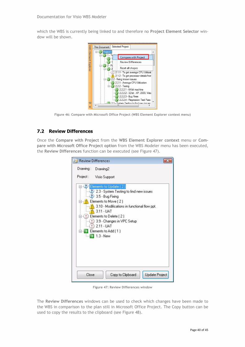
7.2 Review Differences
Once the Compare with Project from the WBS Element Explorer context menu or Com-
pare with Microsoft Office Project option from the WBS Modeler menu has been executed,
the Review Differences function can be executed (see Figure 47).
Figure 47: Review Differences window
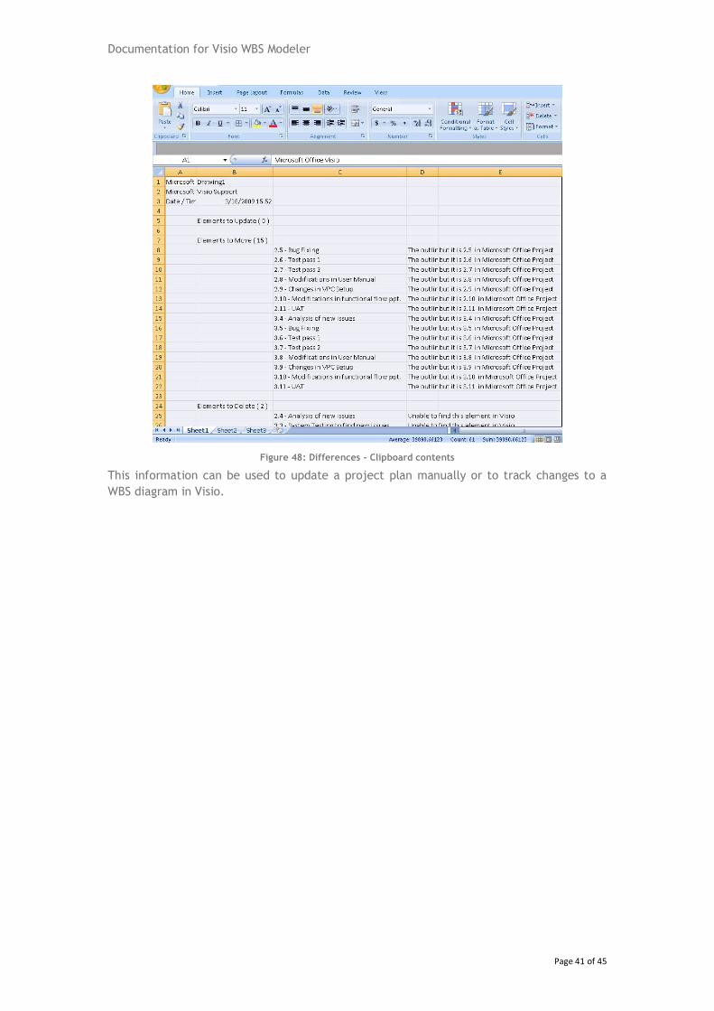
The Review Differences windows can be used to check which changes have been made to
the WBS in comparison to the plan still in Microsoft Office Project. The Copy button can be
used to copy the results to the clipboard (see Figure 48).
Documentation for Visio WBS Modeler
Page 41 of 45
Figure 48: Differences - Clipboard contents
This information can be used to update a project plan manually or to track changes to a
WBS diagram in Visio.
Documentation for Visio WBS Modeler
Page 42 of 45
7.3 Export to Microsoft Office Project
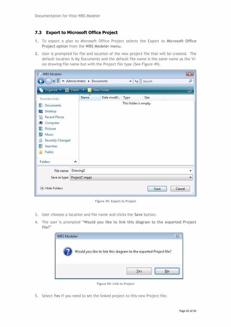
1. To export a plan to Microsoft Office Project selects the Export to Microsoft Office
Project option from the WBS Modeler menu.
2. User is prompted for file and location of the new project file that will be created. The
default location is My Documents and the default file name is the same name as the Vi-
sio drawing file name but with the Project file type (See Figure 49).
Figure 49: Export to Project
3. User chooses a location and file name and clicks the Save button.
4. The user is prompted “Would you like to link this diagram to the exported Project
file?”
Figure 50: Link to Project
5. Select Yes if you need to set the linked project to this new Project file.
Documentation for Visio WBS Modeler
Page 43 of 45
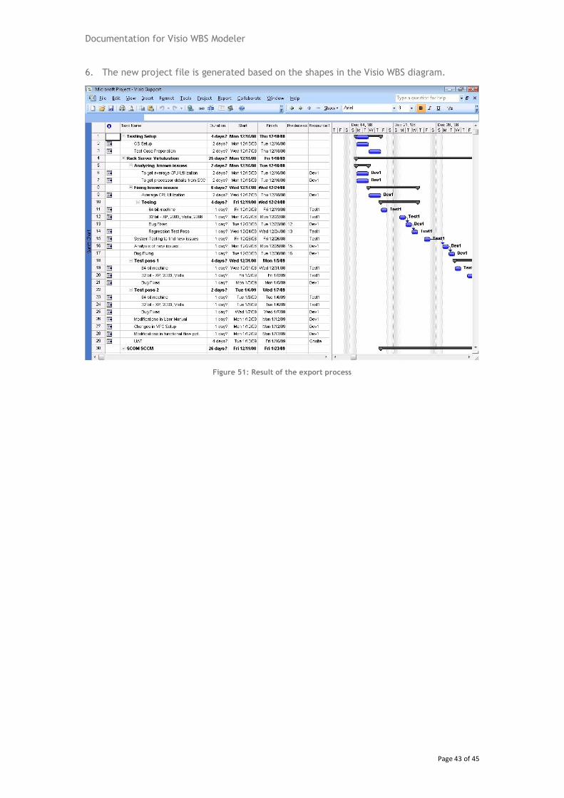
6. The new project file is generated based on the shapes in the Visio WBS diagram.
Figure 51: Result of the export process
Documentation for Visio WBS Modeler
Page 44 of 45
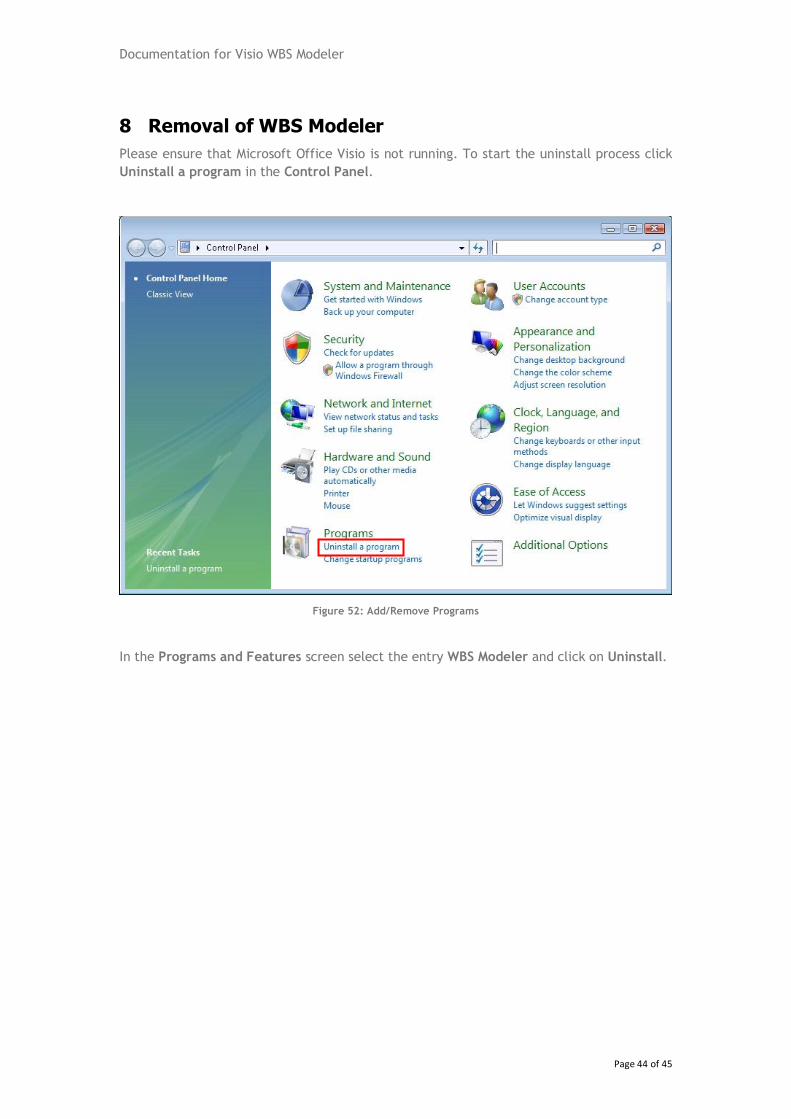
8 Removal of WBS Modeler
Please ensure that Microsoft Office Visio is not running. To start the uninstall process click
Uninstall a program in the Control Panel.
Figure 52: Add/Remove Programs
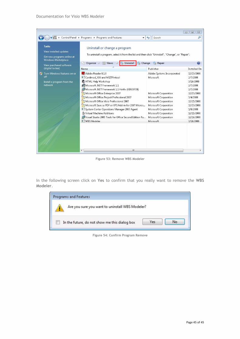
In the Programs and Features screen select the entry WBS Modeler and click on Uninstall.
Documentation for Visio WBS Modeler
Page 45 of 45
Figure 53: Remove WBS Modeler
In the following screen click on Yes to confirm that you really want to remove the WBS
Modeler.
Figure 54: Confirm Program Remove