Embed Size (px)
Citation preview

WEIGHT AND BALANCE MANUAL
LIST OF EFFECTIVE PAGES
* Asterisk indicates pages revised, added or deleted by the current revision.
ANAC APPROVED REVISION 5 A W
B -
135/
1562
- F
AA
LIST OF EFFECTIVE PAGES
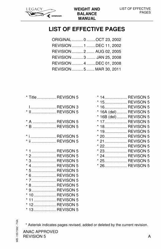
ORIGINAL ..........0 ........OCT 23, 2002
REVISION ..........1 ........DEC 11, 2002
REVISION ..........2 ....... AUG 02, 2005
REVISION ..........3 ........ JAN 25, 2008
REVISION ..........4 ........DEC 01, 2008 REVISION ..........5 ....... MAR 30, 2011
* Title ................. REVISON 5 I ....................... REVISON 3 * II ...................... REVISON 5 * A ..................... REVISON 5 * B ..................... REVISON 5 * i ....................... REVISON 5 * ii ...................... REVISON 5 * 1...................... REVISON 5 * 2...................... REVISON 5 * 3...................... REVISON 5 * 4...................... REVISON 5 * 5...................... REVISON 5 * 6...................... REVISON 5 * 7...................... REVISON 5 * 8...................... REVISON 5 * 9...................... REVISON 5 * 10.................... REVISON 5 * 11.................... REVISON 5 * 12.................... REVISON 5 * 13.................... REVISON 5
* 14.................... REVISON 5 * 15.................... REVISON 5 * 16.................... REVISON 5 * 16A (del) ......... REVISON 5 * 16B (del) ......... REVISON 5 * 17.................... REVISON 5 * 18.................... REVISON 5 * 19.................... REVISON 5 * 20.................... REVISON 5 * 21.................... REVISON 5 * 22.................... REVISON 5 * 23.................... REVISON 5 * 24.................... REVISON 5 * 25.................... REVISON 5 * 26.................... REVISON 5
LIST OF EFFECTIVE PAGES
WEIGHT AND BALANCE MANUAL
ANAC APPROVED
B REVISION 5
WB
-135
/156
2 -
FA
A
INTENTIONALLY BLANK
WEIGHT AND BALANCE MANUAL
WEIGHT AND BALANCE
ANAC APPROVED REVISION 5 i
WB
-135
/156
2 - F
AA
TABLE OF CONTENTS
GENERAL............................................................................................ 1 STANDARD TERMS AND DEFINITIONS........................................... 2 WEIGHING FACILITIES...................................................................... 4
WEIGHING EQUIPMENT............................................................... 4 WEIGHING INSTRUCTIONS......................................................... 4
PASSENGERS.................................................................................... 5 PASSENGER LOCATION.............................................................. 5 PASSENGER WEIGHT.................................................................. 5
BAGGAGE LOADING.......................................................................... 6 BAGGAGE WEIGHT AND LOCATION.......................................... 6 BAGGAGE LOADING PROCEDURES.......................................... 6 CARRY-ON BAGGAGE ................................................................. 6 BAGGAGE COMPARTMENT ........................................................ 6
BALANCE REFERENCE SYSTEM..................................................... 7 BALANCE ARMS/BODY STATION ............................................... 7
AIRPLANE JACKING .......................................................................... 9 JACK POINTS LOCATION............................................................. 9
MAXIMUM GROSS WEIGHT AND CENTER OF GRAVITY LIMITS ..................................................................................... 10
CG CONSTRAINTS ..................................................................... 10 CG ENVELOPE FOR OPERATION............................................. 10 CG ENVELOPE FOR JACKING .................................................. 11 MOMENT/CG CHANGES ............................................................ 12
FUEL DATA....................................................................................... 13 FUEL DEFINITIONS..................................................................... 13 FUEL QUANTITIES (LEGACY 600)............................................. 14 FUEL QUANTITIES (LEGACY 650)............................................. 15 FUEL DISTRIBUTION TABLE ..................................................... 16
MISCELLANEOUS FLUIDS .............................................................. 22 FLIGHT CREW ITEMS...................................................................... 23 BAGGAGE LOADING........................................................................ 24
BAGGAGE LOADING PROCEDURES........................................ 24 INTERIOR ARRANGEMENT ............................................................ 25
STANDARD CONFIGURATION (EXAMPLE) .............................. 25
WEIGHT AND BALANCE
WEIGHT AND BALANCE MANUAL
ANAC APPROVED ii REVISION 5
WB
-135
/156
2 - F
AA
INTENTIONALLY BLANK
WEIGHT AND BALANCE MANUAL
WEIGHT AND BALANCE
ANAC APPROVED REVISION 5 1
WB
-135
/156
2 - F
AA
GENERAL The Weight and Balance Manual provides instructions referring to the weighing and loading of the EMB-135BJ.
The Instructions and Data herein presented are approved by the Airworthiness Authority to comply with the applicable regulations.
The Basic Empty Weight value obtained during the airplane weighing procedures should be used as point of departure for each loading operation.
Based on the contained information, the operator can determine the airplane weight and CG at any time of flight.
WEIGHT AND BALANCE
WEIGHT AND BALANCE MANUAL
ANAC APPROVED 2 REVISION 5
WB
-135
/156
2 - F
AA
STANDARD TERMS AND DEFINITIONS
EQUIPPED EMPTY WEIGHT (EEW) OR MANUFACTURER EMPTY WEIGHT (MEW)
It is the weight of structure, power plant, instruments, interior furnishings, systems, optional, portable, and emergency equipment and other items of equipment that are an integral part of the airplane configuration. It is essentially a dry weight, including only those fluids contained in closed systems such as oxygen, fire extinguisher agent, landing gear shock absorber fluid, etc...
BASIC EMPTY WEIGHT (BEW)
It is the MEW plus the weight of the following items:
− APU oil; − Engine oil; − Hydraulic fluid; − Unusable fuel.
OPERATIONAL EMPTY WEIGHT (OEW)
It is the BEW plus the weight of the operational items.
Operational items are those necessary for airplane operation and not included in the BEW.
The operational items are:
− Crew and crew baggage; − Navigation kit (manuals, charts, etc.); − Catering (beverages and foods) and removable service
equipment for galley (such as standard units, etc.); − Lavatory rinse water; − Lavatory chemical fluid.
ACTUAL ZERO FUEL WEIGHT (AZFW)
This is the OEW plus actual payload.
WEIGHT AND BALANCE MANUAL
WEIGHT AND BALANCE
ANAC APPROVED REVISION 5 3
WB
-135
/156
2 - F
AA
PAYLOAD
This is the weight of passengers, baggage and cargo.
MAXIMUM ALLOWABLE PAYLOAD
It is the maximum approved payload that can be loaded into the airplane. Such value varies with the fuel loaded into the fuselage tanks. The following formula defines the Maximum Allowable Payload:
Maximum Allowable Payload = MZWFW – (fuel in fuselage tanks) – OEW
As a consequence, if fuselage tanks are empty, then Maximum Payload is the Maximum Zero Wing Fuel Weight (MZWFW) less Operational Empty Weight (OEW).
MAXIMUM DESIGN ZERO WING FUEL WEIGHT (MZWFW)
This is the maximum authorized weight before usable fuel be loaded in the wings. The MZWFW is related to airplane structural limitations.
MAXIMUM DESIGN RAMP WEIGHT (MRW)
This is the maximum authorized ramp weight.
MAXIMUM DESIGN TAKEOFF WEIGHT (MTOW)
This is the maximum authorized weight for takeoff.
MAXIMUM DESIGN LANDING WEIGHT (MLW)
This is the maximum authorized weight for landing.
MINIMUM OPERATING WEIGHT (MOW)
This is the minimum authorized weight to operate the airplane.
WEIGHT AND BALANCE
WEIGHT AND BALANCE MANUAL
ANAC APPROVED 4 REVISION 5
WB
-135
/156
2 - F
AA
WEIGHING FACILITIES The airplane should be weighed inside a closed facility that will:
− Exclude all wind and drafts. − Permit shutdown of air conditioning during the weighing
operation. − Maintain a relatively constant temperature for at least 4 hours. − Provide a level weighing floor and sufficient head room.
WEIGHING EQUIPMENT The airplane may be weighed by either of the following methods:
− On wheels. − Jack points.
In both conditions, the weighing equipment manufacturer instructions should be followed.
NOTE: When performing a weighing procedure, assure that the weighing equipment is properly calibrated.
The primary equipment required for weighing the airplane consists of:
− Weighing scale (electronic or mechanical). − Jacking equipment. − Leveling equipment.
WEIGHING INSTRUCTIONS Periodic weighing of the airplane may be required to keep the MEW and BEW current.
Frequency of weighing is to be determined by the operator, in accordance with current standards.
All changes to the airplane affecting weight and balance are the responsibility of the airplane operator.
For further information on airplane weighing instructions refer to Chapter 8 of the Aircraft Maintenance Manual.
WEIGHT AND BALANCE MANUAL
WEIGHT AND BALANCE
ANAC APPROVED REVISION 5 5
WB
-135
/156
2 - F
AA
PASSENGERS
PASSENGER LOCATION The passengers location and respective balance arms are shown in the applicable Interior Arrangement. Seats are numbered sequentially from the left to the right, and from the front to the rear. The seat numbers are for the identification on the Interior Arrangement list and may not necessarily coincide with the actual seating identification on the airplane standard configuration. Enclosed, it is presented the Standard Configuration, including the plan view and the Balance Arms.
For other interior configuration options, the passengers location and respective balance arms are supplied together with the “Airplane Weighing Form”, inserted in the “FINAL INSPECTION REPORT”, by the time of the airplane delivering.
PASSENGER WEIGHT Actual or average passenger weights may be used to compute passenger loads.
Actual passenger weights should be used in case of flights carrying large groups of passengers whose average weight obviously does not conform with the normal standard weight such as athletic squads or other groups which are smaller or larger than the local average. The actual passenger weight may be either determined by scale weighing of each passenger, or by asking each passenger their weight and adding there to a predetermined constant to compensate the handcarryed articles and clothing.
The following standard average weight may be adopted:
− Adult passenger ............................... 180 lb Summer 185 lb Winter
− Children (age 2-12) .......................... 80 lb
NOTE: - Adult passenger weight includes 20 lb of carry-on baggage. - Children under age 2 are considered "babies-in-arms" and
children over age 12 should be treated as adult passengers for purposes of standard average weights.
WEIGHT AND BALANCE
WEIGHT AND BALANCE MANUAL
ANAC APPROVED 6 REVISION 5
WB
-135
/156
2 - F
AA
BAGGAGE LOADING
BAGGAGE WEIGHT AND LOCATION The baggage weight limits, location and the respective balance arm may be obtained from the applicable interior arrangement. The data shown enclosed are applicable to the Standard Configuration. For other interior configuration options, the weight limits, location and the respective balance arm are supplied together with the “Airplane Weighing Form”, inserted in the “FINAL INSPECTION REPORT”.
BAGGAGE LOADING PROCEDURES Refer to the applicable weight and balance data.
CARRY-ON BAGGAGE Carry-on volumes may be stowed in the forward and afterward wardrobes.
There is no specific requirement for underseat carry-on volumes; however a maximum of 20.0 lb is allowable, provided the volume is properly restrained to avoid sliding.
BAGGAGE COMPARTMENT The baggage compartment is designed for a maximum floor distributed load of 80 lb/ft2 and a total maximum capacity of 1000 lb.
Baggage and cargo should be evenly distributed over the baggage compartment to avoid load concentration.
Cargo must not become a hazard to the airplane structure or systems as a result of shifting under operational loads. Sharp edges (like wooden or metal containers) or dense cargo (objects significantly more dense than typical passenger baggage) must be placed under the cargo restraint net to prevent shifting.
WEIGHT AND BALANCE MANUAL
WEIGHT AND BALANCE
ANAC APPROVED REVISION 5 7
WB
-135
/156
2 - F
AA
BALANCE REFERENCE SYSTEM BALANCE ARMS/BODY STATION Longitudinal location of the Centers of Gravity (CG) identified throughout this Manual regarding airplane and components will be referred to as Balance Arms. Balance Arms are the distance in meters from the Airplane Datum which is located at the zero station of the fuselage.
Balance Arms (BA) are equivalent to Body Station (BS) on the EMB-135BJ.
AIRPLANE DATUM
The Airplane Datum is a plane, perpendicular to the fuselage centerline, located at 456.50 in ahead of the wing stub front spar.
For external reference, the Datum is located at 570.63 in ahead of the wing jack points.
WEIGHT AND BALANCE
WEIGHT AND BALANCE MANUAL
ANAC APPROVED 8 REVISION 5
WB
-135
/156
2 - F
AA
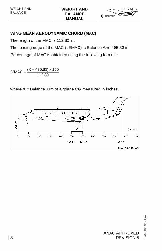
WING MEAN AERODYNAMIC CHORD (MAC)
The length of the MAC is 112.80 in.
The leading edge of the MAC (LEMAC) is Balance Arm 495.83 in.
Percentage of MAC is obtained using the following formula:
112.80100495.83)(XMAC% ×−
=
where X = Balance Arm of airplane CG measured in inches.
WEIGHT AND BALANCE MANUAL
WEIGHT AND BALANCE
ANAC APPROVED REVISION 5 9
WB
-135
/156
2 - F
AA
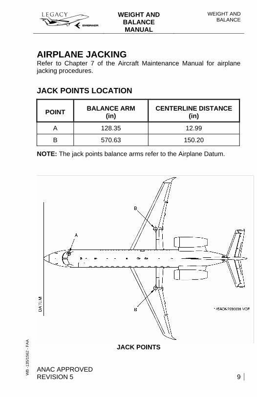
AIRPLANE JACKING Refer to Chapter 7 of the Aircraft Maintenance Manual for airplane jacking procedures.
JACK POINTS LOCATION
POINT BALANCE ARM (in)
CENTERLINE DISTANCE (in)
A 128.35 12.99
B 570.63 150.20
NOTE: The jack points balance arms refer to the Airplane Datum.
JACK POINTS
WEIGHT AND BALANCE
WEIGHT AND BALANCE MANUAL
ANAC APPROVED 10 REVISION 5
WB
-135
/156
2 - F
AA
MAXIMUM GROSS WEIGHT AND CENTER OF GRAVITY LIMITS When performing an approved loading schedule, ensure that the airplane weight and center of gravity remains within the Weight x CG Envelope by accounting for airplane weight and balance with all load conditions.
For maximum structural weights, refer to Airplane Flight Manual (AFM-135/1540).
CG CONSTRAINTS When performing the airplane weighing and balancing, appropriate constraints must be established and applied in order to assure that the center of gravity limits are not exceeded in any airplane operating condition, due to:
− Fuel density variation; − Passenger seat variation; − Cargo location variation; − Landing gear inflight movement; − Passenger and crew member inflight movement.
CG ENVELOPE FOR OPERATION For center of gravity envelopes, refer to Airplane Flight Manual (AFM-135/1540).
WEIGHT AND BALANCE MANUAL
WEIGHT AND BALANCE
ANAC APPROVED REVISION 5 11
WB
-135
/156
2 - F
AA
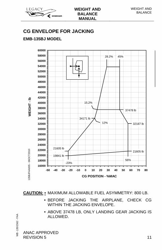
CG ENVELOPE FOR JACKING EMB-135BJ MODEL
16000
18000
20000
22000
24000
26000
28000
30000
32000
34000
36000
38000
40000
42000
44000
46000
48000
50000
52000
54000
56000
58000
60000
-50 -40 -30 -20 -10 0 10 20 30 40 50 60 70 80
CG POSITION - %MAC
135B
JFA
A005
- 06
OC
T201
0
34171 lb
WEI
GH
T - l
b
19841 lb56%
21605 lb
-23%
21605 lb
15.2%
45%
12%
37478 lb
32187 lb
28.2%
CAUTION: • MAXIMUM ALLOWABLE FUEL ASYMMETRY: 800 LB.
• BEFORE JACKING THE AIRPLANE, CHECK CG WITHIN THE JACKING ENVELOPE.
• ABOVE 37478 LB, ONLY LANDING GEAR JACKING IS ALLOWED.
WEIGHT AND BALANCE
WEIGHT AND BALANCE MANUAL
ANAC APPROVED 12 REVISION 5
WB
-135
/156
2 - F
AA
MOMENT/CG CHANGES
DUE TO LANDING GEAR CONFIGURATION
When the landing gear is retracted, there is a reduction of 14890 lb.in of the moment in respect to the airplane datum.
− For 28660 lb: CG moves forward 0.4% of MAC. − For 49604 lb: CG moves forward 0.3% of MAC. − For 53572 lb: CG moves forward 0.25% of MAC.
DUE TO FUEL CONSUMPTION AND DENSITY VARIATION TEMPERATURE
The fuel CG variation with the consumption is shown in the Fuel Distribution Table (the fuel CG changes for different fuel volumes).
The variation of fuel density with temperature has negligible effects in the airplane CG.
WEIGHT AND BALANCE MANUAL
WEIGHT AND BALANCE
ANAC APPROVED REVISION 5 13
WB
-135
/156
2 - F
AA
FUEL DATA
FUEL DEFINITIONS − USABLE FUEL - Is the fuel to be effectively consumed by the
engines.
− UNUSABLE FUEL - Is the fuel remaining after a fuel runout test has been accomplished.
− DRAINABLE FUEL - Is that portion of fuel which can be drawn off through fuel drains with the airplane leveled.
− UNDRAINABLE FUEL - Is that portion of fuel which can not be drawn off by standard draining procedures.
WEIGHT AND BALANCE
WEIGHT AND BALANCE MANUAL
ANAC APPROVED 14 REVISION 5
WB
-135
/156
2 - F
AA
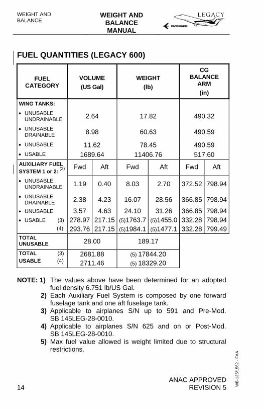
FUEL QUANTITIES (LEGACY 600)
FUEL CATEGORY
VOLUME (US Gal)
WEIGHT (lb)
CG BALANCE
ARM (in)
WING TANKS: • UNUSABLE
UNDRAINABLE 2.64 17.82 490.32
• UNUSABLE DRAINABLE 8.98 60.63 490.59
• UNUSABLE 11.62 78.45 490.59 • USABLE 1689.64 11406.76 517.60 AUXILIARY FUEL SYSTEM 1 or 2: (2)
Fwd Aft Fwd Aft Fwd Aft
• UNUSABLE UNDRAINABLE 1.19 0.40 8.03 2.70 372.52 798.94
• UNUSABLE DRAINABLE 2.38 4.23 16.07 28.56 366.85 798.94
• UNUSABLE 3.57 4.63 24.10 31.26 366.85 798.94• USABLE (3) (4)
278.97293.76
217.15217.15
(5)1763.7(5)1984.1
(5)1455.0(5)1477.1
332.28332.28
798.94799.49
TOTAL UNUSABLE 28.00 189.17
TOTAL (3) USABLE (4)
2681.88 2711.46
(5) 17844.20 (5) 18329.20
NOTE: 1) The values above have been determined for an adopted fuel density 6.751 lb/US Gal.
2) Each Auxiliary Fuel System is composed by one forward fuselage tank and one aft fuselage tank.
3) Applicable to airplanes S/N up to 591 and Pre-Mod. SB 145LEG-28-0010.
4) Applicable to airplanes S/N 625 and on or Post-Mod. SB 145LEG-28-0010.
5) Max fuel value allowed is weight limited due to structural restrictions.
WEIGHT AND BALANCE MANUAL
WEIGHT AND BALANCE
ANAC APPROVED REVISION 5 15
WB
-135
/156
2 - F
AA
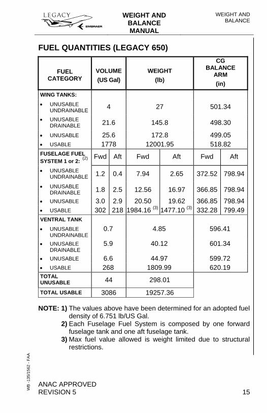
FUEL QUANTITIES (LEGACY 650)
FUEL CATEGORY
VOLUME (US Gal)
WEIGHT (lb)
CG BALANCE
ARM (in)
WING TANKS: • UNUSABLE
UNDRAINABLE 4 27 501.34
• UNUSABLE DRAINABLE 21.6 145.8 498.30
• UNUSABLE 25.6 172.8 499.05 • USABLE 1778 12001.95 518.82 FUSELAGE FUEL SYSTEM 1 or 2: (2)
Fwd Aft Fwd Aft Fwd Aft
• UNUSABLE UNDRAINABLE 1.2 0.4 7.94 2.65 372.52 798.94
• UNUSABLE DRAINABLE 1.8 2.5 12.56 16.97 366.85 798.94
• UNUSABLE 3.0 2.9 20.50 19.62 366.85 798.94• USABLE 302 218 1984.16 (3) 1477.10 (3) 332.28 799.49VENTRAL TANK • UNUSABLE
UNDRAINABLE 0.7 4.85 596.41
• UNUSABLE DRAINABLE
5.9 40.12 601.34
• UNUSABLE 6.6 44.97 599.72 • USABLE 268 1809.99 620.19 TOTAL UNUSABLE 44 298.01
TOTAL USABLE 3086 19257.36
NOTE: 1) The values above have been determined for an adopted fuel density of 6.751 lb/US Gal.
2) Each Fuselage Fuel System is composed by one forward fuselage tank and one aft fuselage tank.
3) Max fuel value allowed is weight limited due to structural restrictions.
WEIGHT AND BALANCE
WEIGHT AND BALANCE MANUAL
ANAC APPROVED 16 REVISION 5
WB
-135
/156
2 - F
AA
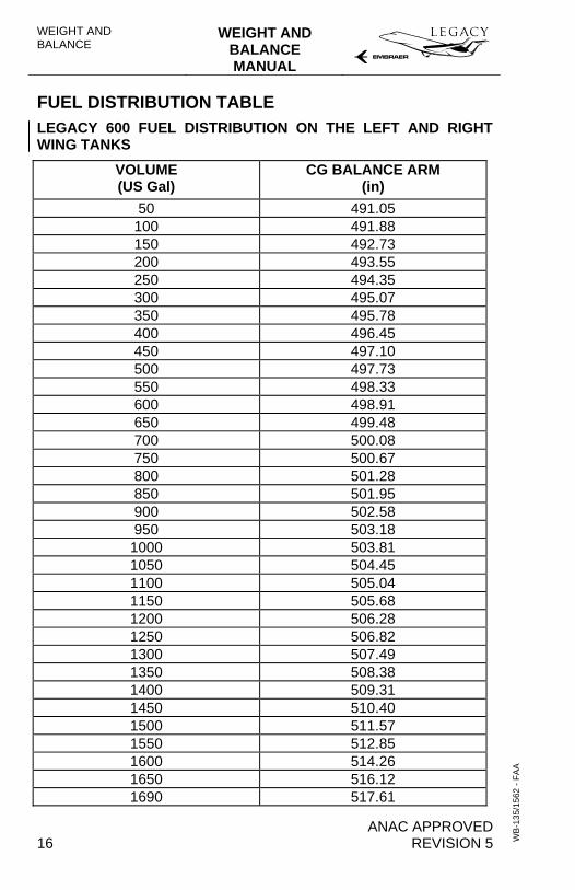
FUEL DISTRIBUTION TABLE LEGACY 600 FUEL DISTRIBUTION ON THE LEFT AND RIGHT WING TANKS
VOLUME (US Gal)
CG BALANCE ARM (in)
50 491.05 100 491.88 150 492.73 200 493.55 250 494.35 300 495.07 350 495.78 400 496.45 450 497.10 500 497.73 550 498.33 600 498.91 650 499.48 700 500.08 750 500.67 800 501.28 850 501.95 900 502.58 950 503.18 1000 503.81 1050 504.45 1100 505.04 1150 505.68 1200 506.28 1250 506.82 1300 507.49 1350 508.38 1400 509.31 1450 510.40 1500 511.57 1550 512.85 1600 514.26 1650 516.12 1690 517.61
WEIGHT AND BALANCE MANUAL
WEIGHT AND BALANCE
ANAC APPROVED REVISION 5 17
WB
-135
/156
2 - F
AA
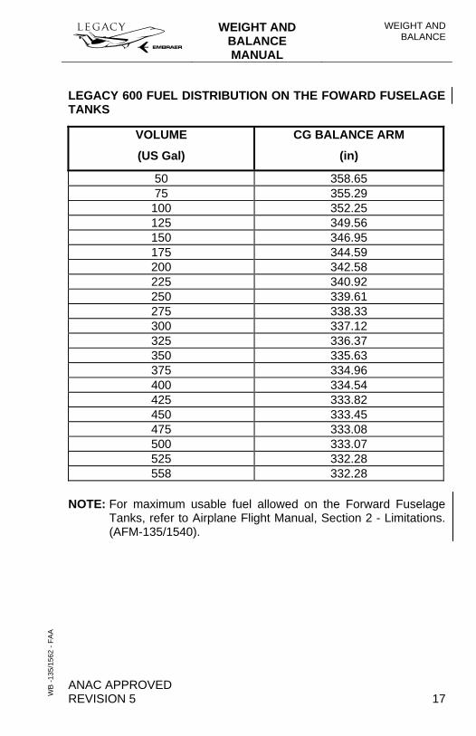
LEGACY 600 FUEL DISTRIBUTION ON THE FOWARD FUSELAGE TANKS
VOLUME
(US Gal)
CG BALANCE ARM
(in)
50 358.65 75 355.29
100 352.25 125 349.56 150 346.95 175 344.59 200 342.58 225 340.92 250 339.61 275 338.33 300 337.12 325 336.37 350 335.63 375 334.96 400 334.54 425 333.82 450 333.45 475 333.08 500 333.07 525 332.28 558 332.28
NOTE: For maximum usable fuel allowed on the Forward Fuselage Tanks, refer to Airplane Flight Manual, Section 2 - Limitations. (AFM-135/1540).
WEIGHT AND BALANCE
WEIGHT AND BALANCE MANUAL
ANAC APPROVED 18 REVISION 5
WB
-135
/156
2 - F
AA
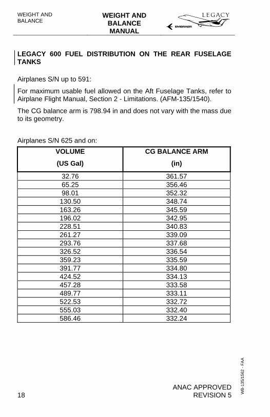
LEGACY 600 FUEL DISTRIBUTION ON THE REAR FUSELAGE TANKS
Airplanes S/N up to 591:
For maximum usable fuel allowed on the Aft Fuselage Tanks, refer to Airplane Flight Manual, Section 2 - Limitations. (AFM-135/1540).
The CG balance arm is 798.94 in and does not vary with the mass due to its geometry.
Airplanes S/N 625 and on:
VOLUME
(US Gal)
CG BALANCE ARM
(in)
32.76 361.57 65.25 356.46 98.01 352.32
130.50 348.74 163.26 345.59 196.02 342.95 228.51 340.83 261.27 339.09 293.76 337.68 326.52 336.54 359.23 335.59 391.77 334.80 424.52 334.13 457.28 333.58 489.77 333.11 522.53 332.72 555.03 332.40 586.46 332.24
WEIGHT AND BALANCE MANUAL
WEIGHT AND BALANCE
ANAC APPROVED REVISION 5 19
WB
-135
/156
2 - F
AA
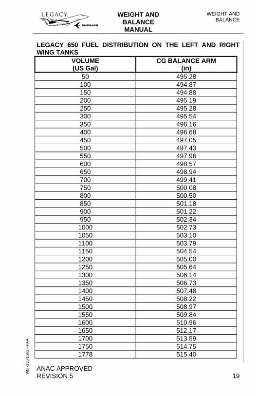
LEGACY 650 FUEL DISTRIBUTION ON THE LEFT AND RIGHT WING TANKS
VOLUME (US Gal)
CG BALANCE ARM (in)
50 495.28 100 494.87 150 494.88 200 495.19 250 495.28 300 495.54 350 496.16 400 496.68 450 497.05 500 497.43 550 497.96 600 498.57 650 498.94 700 499.41 750 500.08 800 500.50 850 501.18 900 501.22 950 502.34 1000 502.73 1050 503.10 1100 503.79 1150 504.54 1200 505.00 1250 505.64 1300 506.14 1350 506.73 1400 507.48 1450 508.22 1500 508.97 1550 509.84 1600 510.96 1650 512.17 1700 513.59 1750 514.75 1778 515.40
WEIGHT AND BALANCE
WEIGHT AND BALANCE MANUAL
ANAC APPROVED 20 REVISION 5
WB
-135
/156
2 - F
AA
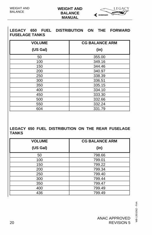
LEGACY 650 FUEL DISTRIBUTION ON THE FORWARD FUSELAGE TANKS
VOLUME
(US Gal)
CG BALANCE ARM
(in)
50 355.00 100 349.16 150 344.46 200 340.97 250 338.39 300 336.51 350 335.15 400 334.10 450 333.30 500 332.66 550 332.24 604 331.79
LEGACY 650 FUEL DISTRIBUTION ON THE REAR FUSELAGE TANKS
VOLUME
(US Gal)
CG BALANCE ARM
(in)
50 798.66 100 799.01 150 799.22 200 799.34 250 799.40 300 799.44 350 799.47 400 799.49 436 799.49
WEIGHT AND BALANCE MANUAL
WEIGHT AND BALANCE
ANAC APPROVED REVISION 5 21
WB
-135
/156
2 - F
AA
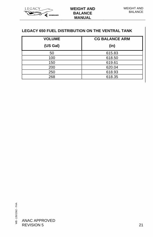
LEGACY 650 FUEL DISTRIBUTION ON THE VENTRAL TANK
VOLUME
(US Gal)
CG BALANCE ARM
(in)
50 615.83 100 618.50 150 619.61 200 620.04 250 618.93 268 618.35
WEIGHT AND BALANCE
WEIGHT AND BALANCE MANUAL
ANAC APPROVED 22 REVISION 5
WB
-135
/156
2 - F
AA
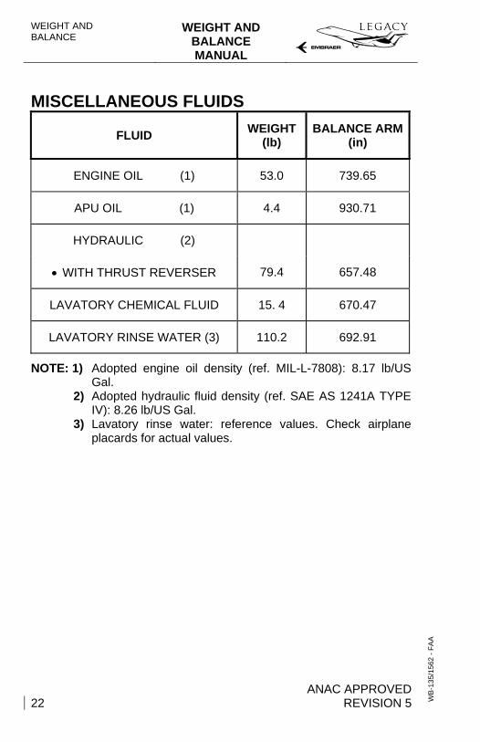
MISCELLANEOUS FLUIDS
FLUID WEIGHT (lb)
BALANCE ARM(in)
ENGINE OIL (1) 53.0 739.65
APU OIL (1) 4.4 930.71
HYDRAULIC (2)
• WITH THRUST REVERSER 79.4 657.48
LAVATORY CHEMICAL FLUID 15. 4 670.47
LAVATORY RINSE WATER (3) 110.2 692.91
NOTE: 1) Adopted engine oil density (ref. MIL-L-7808): 8.17 lb/US Gal.
2) Adopted hydraulic fluid density (ref. SAE AS 1241A TYPE IV): 8.26 lb/US Gal.
3) Lavatory rinse water: reference values. Check airplane placards for actual values.
WEIGHT AND BALANCE MANUAL
WEIGHT AND BALANCE
ANAC APPROVED REVISION 5 23
WB
-135
/156
2 - F
AA
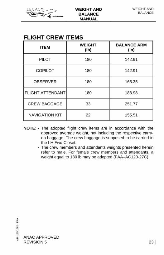
FLIGHT CREW ITEMS ITEM WEIGHT
(lb) BALANCE ARM
(in)
PILOT 180 142.91
COPILOT 180 142.91
OBSERVER 180 165.35
FLIGHT ATTENDANT 180 188.98
CREW BAGGAGE 33 251.77
NAVIGATION KIT 22 155.51
NOTE: - The adopted flight crew items are in accordance with the approved average weight, not including the respective carry-on baggage. The crew baggage is supposed to be carried in the LH Fwd Closet.
- The crew members and attendants weights presented herein refer to male. For female crew members and attendants, a weight equal to 130 lb may be adopted (FAA–AC120-27C).
WEIGHT AND BALANCE
WEIGHT AND BALANCE MANUAL
ANAC APPROVED 24 REVISION 5
WB
-135
/156
2 - F
AA
BAGGAGE LOADING
BAGGAGE LOADING PROCEDURES
To load the baggage compartment with the maximum capacity of 1000 lb, no more than 2 people can be at the airplane cone, one inside the baggage compartment and the other inside the rear electronic compartment.
CAUTION: IF THE CONDITIONS ABOVE ARE NOT OBSERVED, AN AIRPLANE TILTING (TAIL DOWN) MAY OCCUR.
WEIGHT AND BALANCE MANUAL
WEIGHT AND BALANCE
ANAC APPROVED REVISION 5 25
WB
-135
/156
2 - F
AA
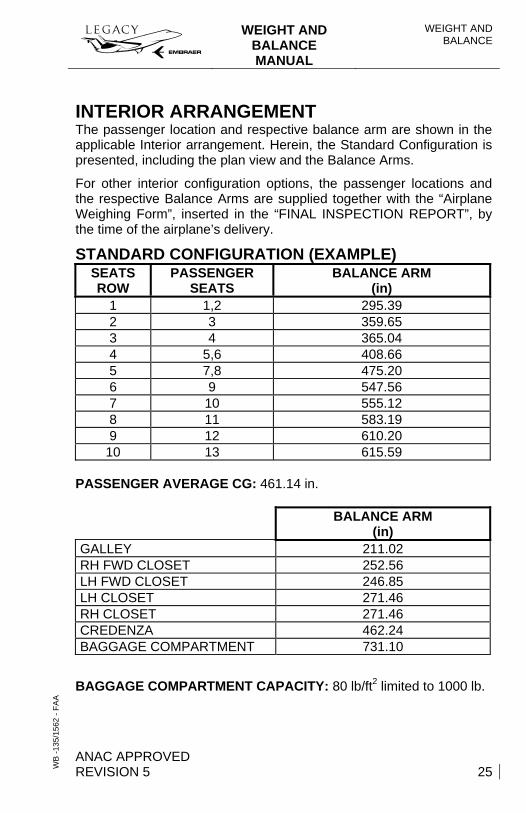
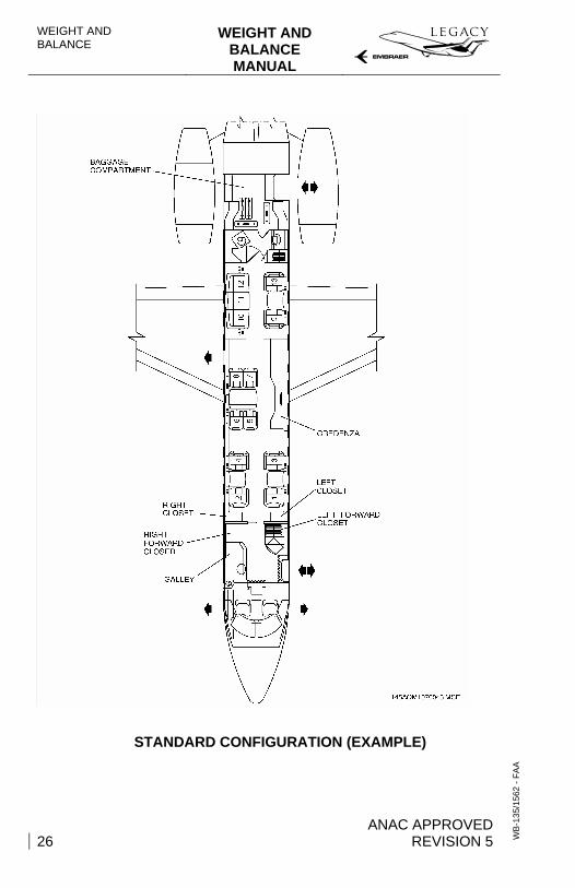
INTERIOR ARRANGEMENT The passenger location and respective balance arm are shown in the applicable Interior arrangement. Herein, the Standard Configuration is presented, including the plan view and the Balance Arms.
For other interior configuration options, the passenger locations and the respective Balance Arms are supplied together with the “Airplane Weighing Form”, inserted in the “FINAL INSPECTION REPORT”, by the time of the airplane’s delivery.
STANDARD CONFIGURATION (EXAMPLE) SEATS ROW
PASSENGER SEATS
BALANCE ARM (in)
1 1,2 295.39 2 3 359.65 3 4 365.04 4 5,6 408.66 5 7,8 475.20 6 9 547.56 7 10 555.12 8 11 583.19 9 12 610.20
10 13 615.59 PASSENGER AVERAGE CG: 461.14 in.
BALANCE ARM (in)
GALLEY 211.02 RH FWD CLOSET 252.56 LH FWD CLOSET 246.85 LH CLOSET 271.46 RH CLOSET 271.46 CREDENZA 462.24 BAGGAGE COMPARTMENT 731.10
BAGGAGE COMPARTMENT CAPACITY: 80 lb/ft2 limited to 1000 lb.
WEIGHT AND BALANCE
WEIGHT AND BALANCE MANUAL
ANAC APPROVED 26 REVISION 5
WB
-135
/156
2 - F
AA
STANDARD CONFIGURATION (EXAMPLE)