Embed Size (px)
Citation preview
Waveguide HOM damping studies at JLab
R. Rimmer et. al. HOM10, Cornell

Outline
• Motivation
• Solution(s)
• 748.5 MHz version
• 1497 MHz version
• Future applications
• SPX crab cavity
– HOM, LOM and SOM damping
– On-cell alternative design
• Conclusions
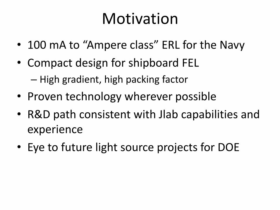
Motivation
• 100 mA to “Ampere class” ERL for the Navy
• Compact design for shipboard FEL
– High gradient, high packing factor
• Proven technology wherever possible
• R&D path consistent with Jlab capabilities and experience
• Eye to future light source projects for DOE
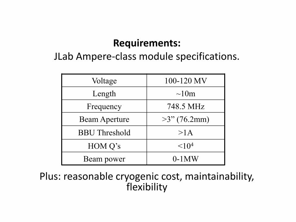
Requirements: JLab Ampere-class module specifications.
Plus: reasonable cryogenic cost, maintainability, flexibility
Voltage 100-120 MV
Length ~10m
Frequency 748.5 MHz
Beam Aperture >3” (76.2mm)
BBU Threshold >1A
HOM Q’s <104
Beam power 0-1MW

Why consider waveguides? • Waveguide is a natural high-pass filter
• High power-handling capability
• Small beamline length required
• Loads can be at higher temperature
• Static loss is tolerable
• Good experience at PEP-II and CEBAF
• Easy to fabricate

Concepts
+ =
Take the best from Jlab experience and high-current storage ring technology.
General layout:
• Symmetrical waveguide-damped 5-cell cavities.
• Six cavities per cryomodule at 16.7 MV/m - 20 MV/m.
• Good packing factor with real-estate gradient ~10-12 MV/m.
• HOM power dissipated at room temperature.
• Cell with a good HOM frequency spectrum.
• High-current optimized cell shape gives good efficiency

Wide range of cell shapes existing (e.g. High Gradient (HG), Low Loss (LL), Original Cornell, ILC)
Storage ring light sources and colliders routinely operate with strongly damped single-cell cavities
Various HOM damping schemes have been investigated for models at 1.5 GHz (MAFIA T3)
Damping of monopole (TM011) and dipole modes (TE111, TM110) can be efficient
Enlarged (fluted) beam tube (e.g. Cornell and KEK SRF cavity designs)
Waveguide dampers (e.g. CEBAF OC)
Coaxial beam pipe dampers (e.g. crab cavity for KEKB)
Enlarged beam tubes on both sides
b-pipe fluted wguide bp-coax 2 x bp
JLAB HC Cryomodule Development Cavity Cell Shape and Number of Cells
Comparably low Qs obtained for all concepts for most parasitic modes (monopole < 8 102, dipole < 1.6 103)
All damping schemes principally suited for next generation ERL’s

Study damping efficiency by adding cells (beam pipe loaded structure)
Damping efficiency better in shorter structures
However: Overhead length of HOM load(s) may reduce the real estate gradient of cryomodule (may want to share HOM loads with adjacent cavities)
TM011 passband mod vs. # cells Enlarged beam tubes (Original Cornell (OC) shape cavity cells)
JLAB HC Cryomodule Development Cavity Cell Shape and Number of Cells
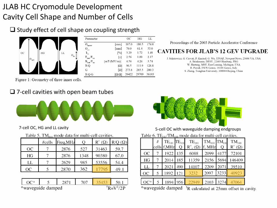
7-cell cavities with open beam tubes
7-cell OC, HG and LL cavity
Study effect of cell shape on coupling strength
5-cell OC with waveguide damping endgroups
JLAB HC Cryomodule Development Cavity Cell Shape and Number of Cells

Cavity cell shape optimization concept for High Current
10
15
20
25
30
35
40
45
0 10 20 30 40
Eacc [MV/m]
Ef [
eV
]
Jlab high-current
Jlab-LL
modified
Jlab-OC
Jlab-HG
Jlab-LL
Round pillbox
LL round top
SNS high-b
BNL High Current
• Optimize shape to keep trapped HOMs (below beam pipe cut-off frequency) away from beam resonance to avoid huge HOM power.
• Preserve reasonable fundamental mode efficiency but maintain the iris size to give good HOM damping.
• Optimized shape also has to avoid multipacting barriers.
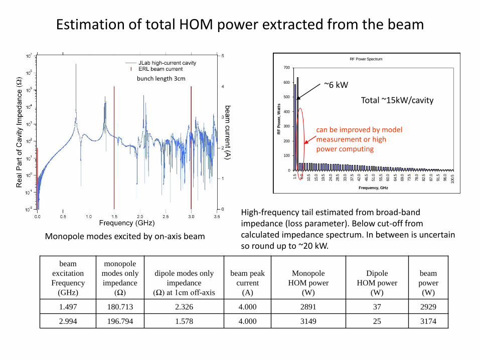
Estimation of total HOM power extracted from the beam
Monopole modes excited by on-axis beam
High-frequency tail estimated from broad-band impedance (loss parameter). Below cut-off from calculated impedance spectrum. In between is uncertain so round up to ~20 kW.
bunch length 3cm
beam
excitation
Frequency
(GHz)
monopole
modes only
impedance
(Ω)
dipole modes only
impedance
(Ω) at 1cm off-axis
beam peak
current
(A)
Monopole
HOM power
(W)
Dipole
HOM power
(W)
beam
power
(W)
1.497 180.713 2.326 4.000 2891 37 2929
2.994 196.794 1.578 4.000 3149 25 3174
RF Power Spectrum
0
100
200
300
400
500
600
700
1.5
6.0
10.5
15.0
19.5
24.0
28.5
33.0
37.5
42.0
46.5
51.0
55.5
60.0
64.5
69.0
73.5
78.0
82.5
87.0
91.5
96.0
100.5
Frequency, GHz
RF
Po
wer,
Watt
s
Total ~15kW/cavity
~6 kW
can be improved by model measurement or high power computing

Copper 5-cell model measurement and data fitting techniques
• S21 from beam pipe to beam pipe. • Labview automation. • Ceramic bead-pull on-axis or off-axis. • End groups staggered 30o or 60o. • 5, 6, 7-cell assembly. • Data sets with dummy loads or shorts. • Rotatable coupling antennas.
• Data set can be fitted by the 5-peak fitting algorithm first developed at LBNL to get freqs and Qs and amplitudes. • Data analysis for mode successful •BBU threshold needs to be verified in compact lattice.
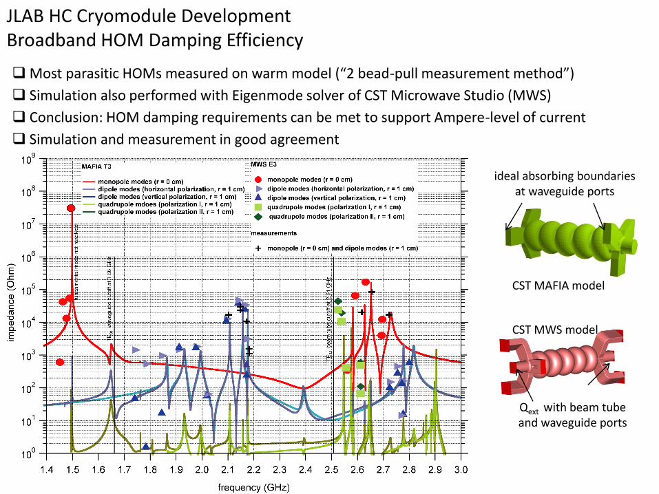
Most parasitic HOMs measured on warm model (“2 bead-pull measurement method”)
Simulation also performed with Eigenmode solver of CST Microwave Studio (MWS)
Conclusion: HOM damping requirements can be met to support Ampere-level of current
JLAB HC Cryomodule Development Broadband HOM Damping Efficiency
Qext with beam tube and waveguide ports
CST MAFIA model
CST MWS model
ideal absorbing boundaries at waveguide ports
Simulation and measurement in good agreement
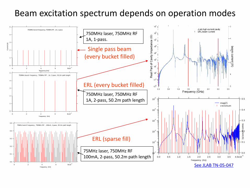
Beam excitation spectrum depends on operation modes 5
4
3
2
1
0
Cu
rre
nt (A
)
8x10⁹
6420
frequency (Hz)
750MHz bunch frequency, 750MHz RF , 1A, 1-pass
5
4
3
2
1
0
Cu
rre
nt (
A)
8x10⁹
6420
f requency (Hz)
750MHz bunch f requency , 750MHz RF , 1A, 2-pass, 50.2m path length
0.5
0.4
0.3
0.2
0.1
0.0
curr
en
t (A
)
8x10⁹
6420
f requency (Hz)
75MHz bunch f requency , 750MHz RF , 100mA, 2-pass, 50.2m path length
101
102
103
104
105
106
Ma
g(Z
) (ž
)
4.0x10⁹
3.53.02.52.01.51.00.50.0
f requency (Hz)
0.5
0.4
0.3
0.2
0.1
0.0
be
am
curre
nt (A
)
mag(Z)
v ectorsum
750MHz laser, 750MHz RF 1A, 1-pass.
750MHz laser, 750MHz RF 1A, 2-pass, 50.2m path length
75MHz laser, 750MHz RF 100mA, 2-pass, 50.2m path length
See JLAB TN-05-047
ERL (every bucket filled)
ERL (sparse fill)
Single pass beam (every bucket filled)
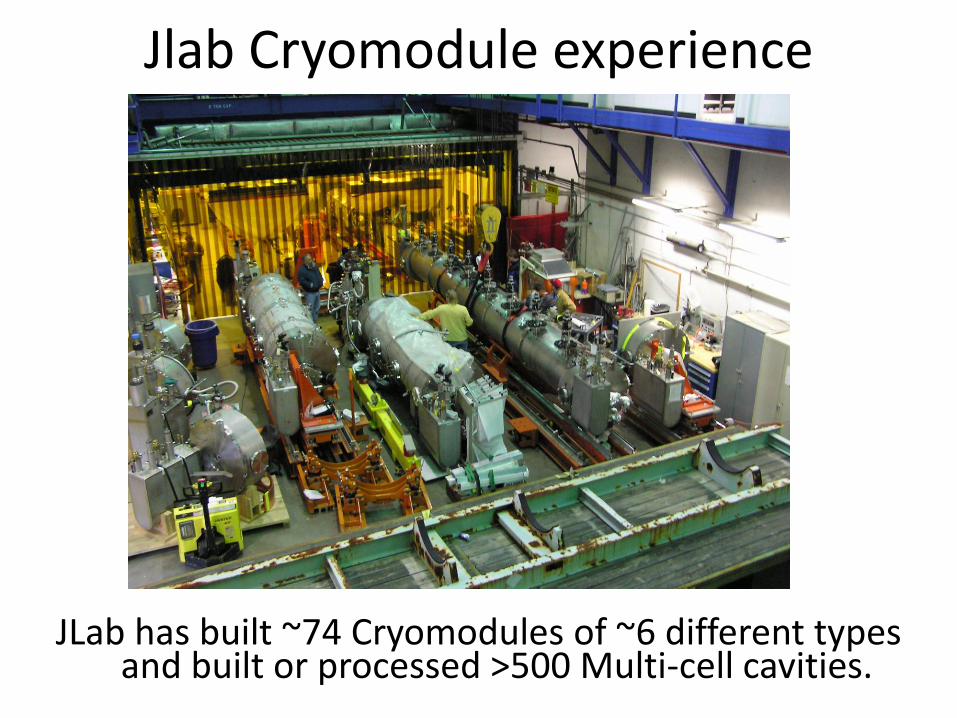
Jlab Cryomodule experience
JLab has built ~74 Cryomodules of ~6 different types and built or processed >500 Multi-cell cavities.
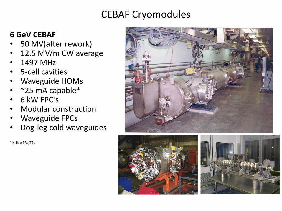
CEBAF Cryomodules
6 GeV CEBAF • 50 MV(after rework) • 12.5 MV/m CW average • 1497 MHz • 5-cell cavities • Waveguide HOMs • ~25 mA capable* • 6 kW FPC’s • Modular construction • Waveguide FPCs • Dog-leg cold waveguides *in Jlab ERL/FEL
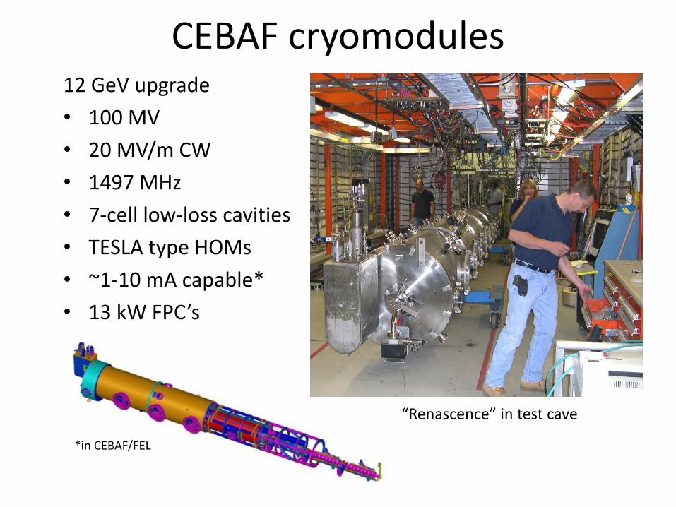
CEBAF cryomodules
*in CEBAF/FEL
12 GeV upgrade
• 100 MV
• 20 MV/m CW
• 1497 MHz
• 7-cell low-loss cavities
• TESLA type HOMs
• ~1-10 mA capable*
• 13 kW FPC’s
“Renascence” in test cave
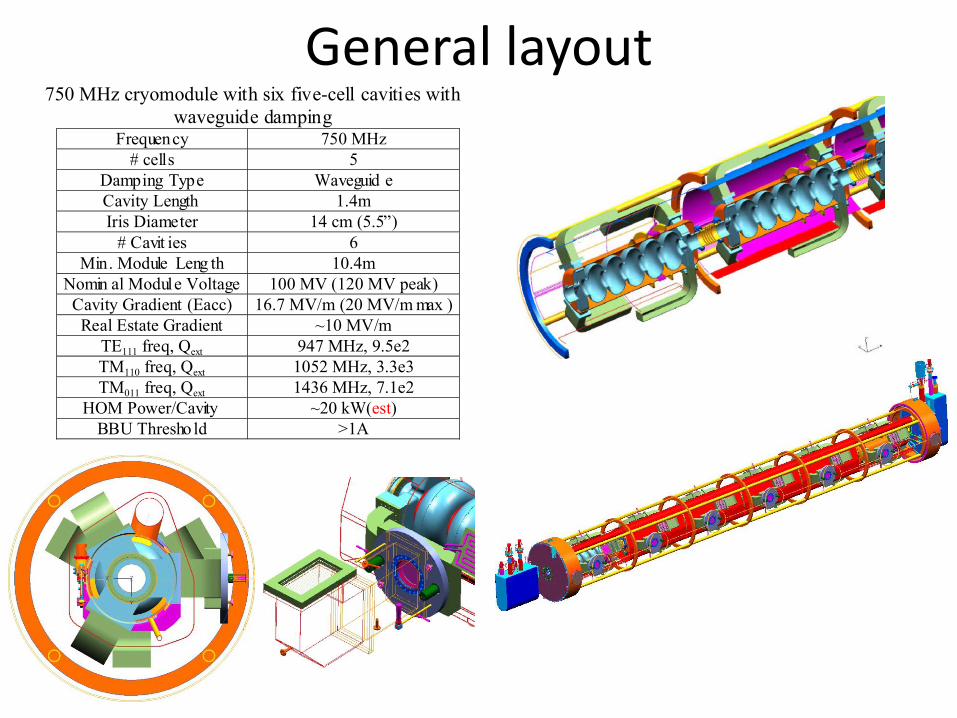
General layout 750 MHz cryomodule with six five-cell cavities with
waveguide dampingFrequency 750 MHz
# cells 5
Damping Type Waveguid e
Cavity Length 1.4m
Iris Diameter 14 cm (5.5”)
# Cavit ies 6
Min. Module Leng th 10.4m
Nomin al Module Voltage 100 MV (120 MV peak)
Cavity Gradient (Eacc) 16.7 MV/m (20 MV/m max )
Real Estate Gradient ~10 MV/m
TE111 freq, Qext 947 MHz, 9.5e2
TM110 freq, Qext 1052 MHz, 3.3e3
TM011 freq, Qext 1436 MHz, 7.1e2
HOM Power/Cavity ~20 kW(est)
BBU Thresho ld >1A
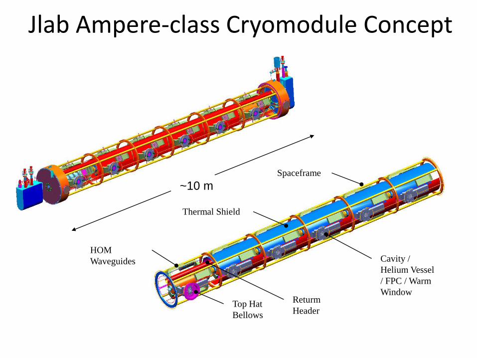
Jlab Ampere-class Cryomodule Concept
Cavity /
Helium Vessel
/ FPC / Warm
Window
Top Hat
Bellows
HOM
Waveguides
Returm
Header
Spaceframe
Thermal Shield
~10 m

Preliminary Heat Load Estimates (748.5 MHz) 2 K 50 K
Static 73 W 362 W
(mainly FPC and HOMs)
Includes u-tubes (10 W @ 2K, 30 W @ 50 K)
May be improved?
Dynamic 382 W 188 W (cavity FPC and HOM RF losses)
Total 455 W 550 W
Coupler Cooling ~ 1 gram/sec cool outer conductors

Helium Supply Transfer
Line Helium Return Transfer
Line HP Helium Supply
Cooldown & Coupler Return Guard Vacuum & Relief
WG
FPC
WG
FPC
WG
FPC
WG
FPC
WG
FPC
WG
FPC Surg
e
Tank
5
Cell
Cavit
y
5
Cell
Cavit
y
5
Cell
Cavit
y
5
Cell
Cavit
y
5
Cell
Cavit
y
5
Cell
Cavit
y
6 ea
HOM
Load
s FPC
Windo
w
Water Return
Water Supply
50 K Shield
Vacuum Vessel Boundary
6 ea
HOM
Load
s FPC
Windo
w
6 ea
HOM
Load
s FPC
Windo
w
6 ea
HOM
Load
s FPC
Windo
w
6 ea
HOM
Load
s FPC
Windo
w
6 ea
HOM
Load
s FPC
Windo
w
Cryomodule Flow Schematic
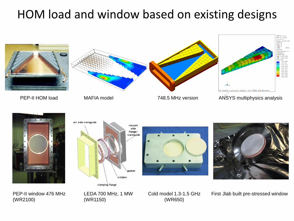
HOM load and window based on existing designs
PEP-II HOM load MAFIA model 748.5 MHz version ANSYS multiphysics analysis
PEP-II window 476 MHz
(WR2100)
LEDA 700 MHz, 1 MW
(WR1150)
Cold model 1.3-1.5 GHz
(WR650)
First Jlab built pre-stressed window
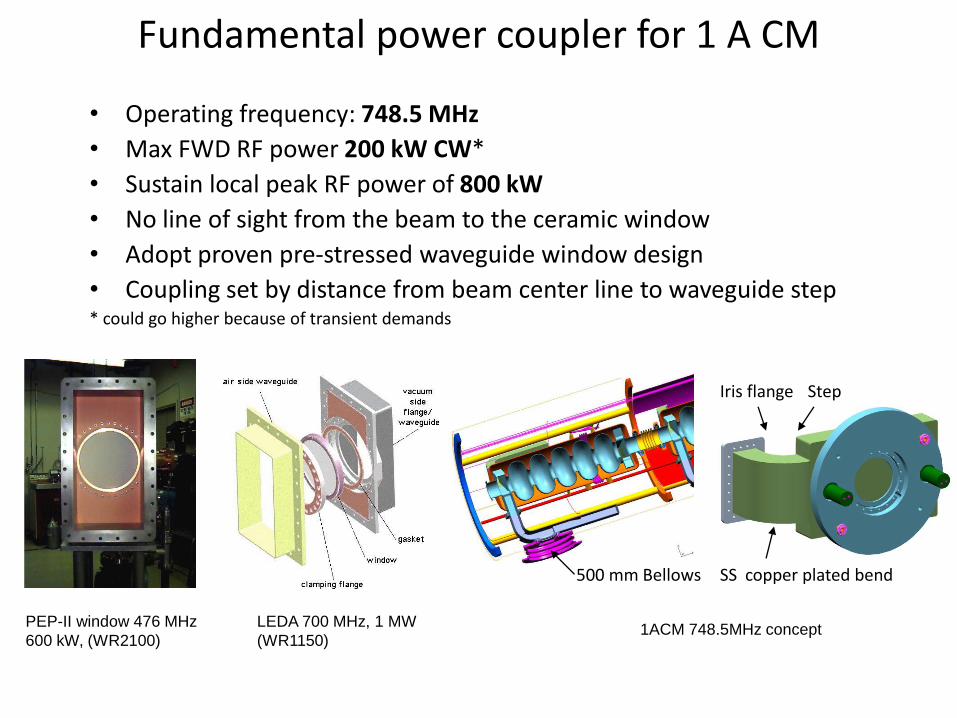
Fundamental power coupler for 1 A CM
• Operating frequency: 748.5 MHz
• Max FWD RF power 200 kW CW*
• Sustain local peak RF power of 800 kW
• No line of sight from the beam to the ceramic window
• Adopt proven pre-stressed waveguide window design
• Coupling set by distance from beam center line to waveguide step * could go higher because of transient demands
Iris flange
SS copper plated bend 500 mm Bellows
PEP-II window 476 MHz
600 kW, (WR2100)
LEDA 700 MHz, 1 MW
(WR1150) 1ACM 748.5MHz concept
Step

HOM load
• RF heat summary
• Joule heat densities
Freq.
GHz
Input
Power, W
Dielectric
Loss, W
Surface
loss, W
Total
power
loss, W
1.497 1775.200 1764.876 7.7799 1772.6557
2.994 1923.921 1909.972 8.6038 1918.5754
4.5 150.700 149.195 0.8314 150.0267
6 150.179 148.113 1.0018 149.1147
Sum 4000 3972.156 18.217 3990.372
99.5% of the RF heat is absorbed in tiles. Only
~0.5% surface heat loss.
Joule heat densities at the interested
four frequencies are calculated and
superimposed for thermal analysis.
High-power HOM load concept
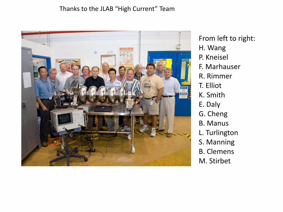
Thanks to the JLAB “High Current” Team
From left to right: H. Wang P. Kneisel F. Marhauser R. Rimmer T. Elliot K. Smith E. Daly G. Cheng B. Manus L. Turlington S. Manning B. Clemens M. Stirbet

748.5 MHz HC first tests
Multipacting seen from 3 MV/m
but processed away in a few
hours. FE/RF power limited. Bulk BCP only, no furnace outgas
No Multipacting, RF power limited
Bulk BCP + 600C furnace outgass
+ light BCP

JLab 1497 MHz high-current cryomodules
• Two half-scale prototypes of FEL high current cavity built and tested
– Results exceed requirements for 4th gen. light source
– Planned to build demo cryounit for beam test in FEL.

JLAB 1497 MHz HC Cryomodule Development
Conceptual design of a cavity-pair injector cryomodule (L=2.6m)
fundamental power couplers
HOM waveguide with load
two-phase He return header line
high power rf window “dogleg”
chicane
50 K heat station
He fill line
HOM end group
Cavity He vessel
F. Marhauser ERL09
HC optimized cell shape, 5 cells, WG FPC, WG HOMs Planned for beam test in JLab FEL in 2010 (funding lost)

JLab 10 kW FEL • Fourth-generation light source with energy recovery
• The IR branch is operational (14 kW world record), while the UV branch is now under commissioning.
IR Branch UV Branch
(under construction)
Wavelength range
(microns)
1.5 – 14 0.25 - 1
Bunch Length
(FWHM psec )
0.2 - 2 0.2 - 2
Laser power (kW) > 10 > 1
Repetition Rate ( cw
operation, MHz)
4.7 – 75 4.7 - 75
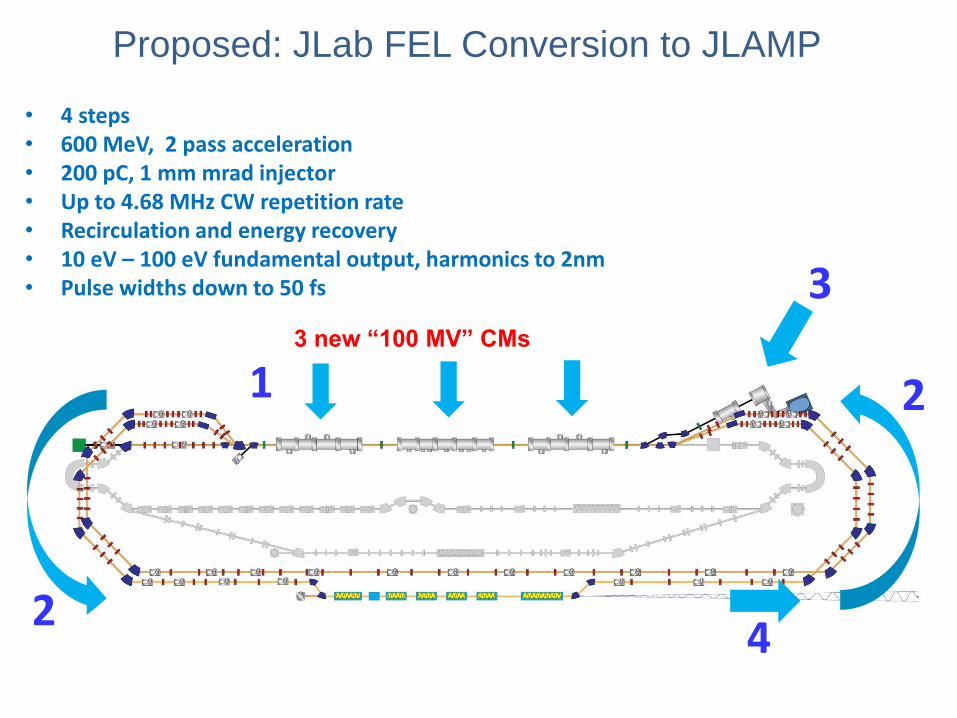
Proposed: JLab FEL Conversion to JLAMP
• 4 steps • 600 MeV, 2 pass acceleration • 200 pC, 1 mm mrad injector • Up to 4.68 MHz CW repetition rate • Recirculation and energy recovery • 10 eV – 100 eV fundamental output, harmonics to 2nm • Pulse widths down to 50 fs
1
2
2
3
4
3 new “100 MV” CMs

New Hall
SCOPE OF 12 GeV UPGRADE
Scope of the proposed project includes
doubling the accelerator beam
energy, a new experimental Hall and
associated beamline, and upgrades
to the existing three experimental Halls.
Upgrade is designed to build on existing facility:
vast majority of accelerator and experimental equipment have continued use
Add arc
Enhanced capabilities
in existing Halls
Add 5
cryomodules
Add 5
cryomodules
20 cryomodules
20 cryomodules

New applications • ANL SPX baseline cavity
– Up to 200 mA, 2x 8-cavity CM required
– Strong HOM/LOM/SOM damping required
– Possibility of moderate HOM power to loads
– Short space available
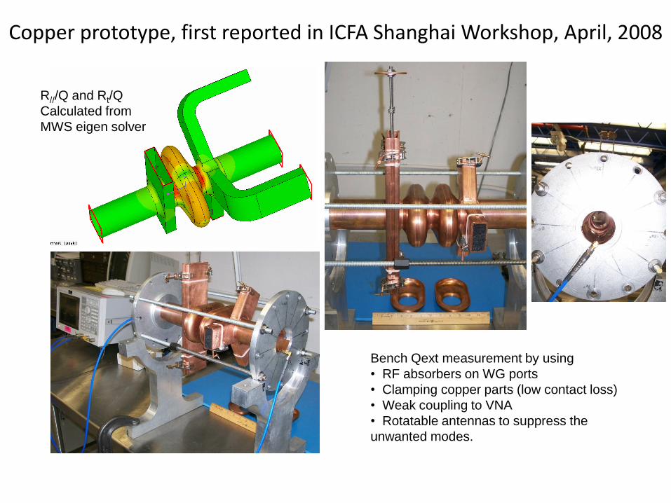
Copper prototype, first reported in ICFA Shanghai Workshop, April, 2008
R///Q and Rt/Q
Calculated from
MWS eigen solver
Bench Qext measurement by using
• RF absorbers on WG ports
• Clamping copper parts (low contact loss)
• Weak coupling to VNA
• Rotatable antennas to suppress the
unwanted modes.

Single-cell cavity LOM/HOM WG damper cryostat solution update
1-D RF-thermal model with SS WG, flange
interface (AlMg seal) and heat station for HOM
waveguides
=2 inch
=12.25 inch
=7.25 inch
Optimized lengths
=0.314W static
=4.33W static
=-4.59 W static
TNb=4.61K (max)
LOM WG is shorter than HOM
WGs due to fast decay of magnetic
field.
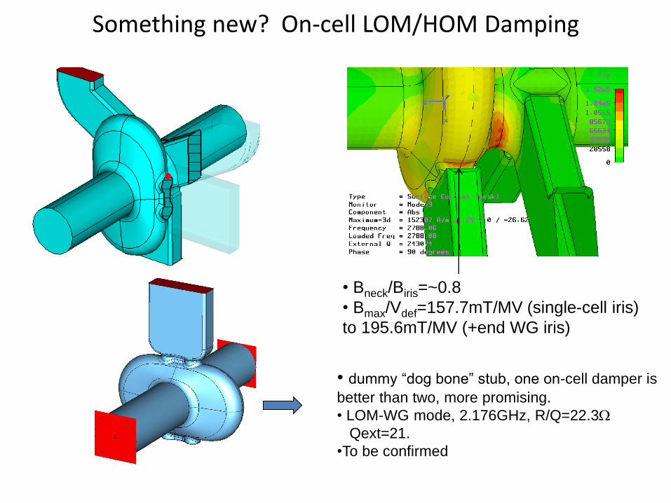
Something new? On-cell LOM/HOM Damping
• Bneck/Biris=~0.8
• Bmax/Vdef=157.7mT/MV (single-cell iris)
to 195.6mT/MV (+end WG iris)
• dummy “dog bone” stub, one on-cell damper is
better than two, more promising.
• LOM-WG mode, 2.176GHz, R/Q=22.3W
Qext=21.
•To be confirmed
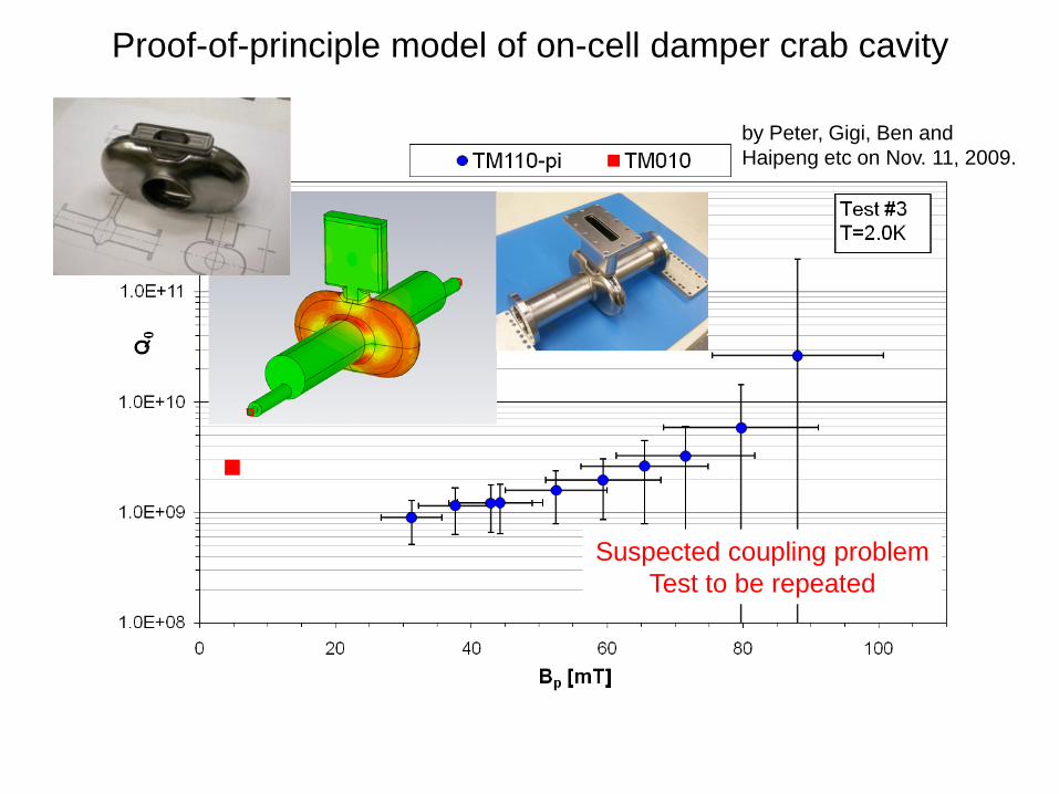
Proof-of-principle model of on-cell damper crab cavity
by Peter, Gigi, Ben and
Haipeng etc on Nov. 11, 2009.
Suspected coupling problem
Test to be repeated

High-current Proton driver cavity? • Development from electron cavity for ≥100 mA
F. Marhauser PAC09
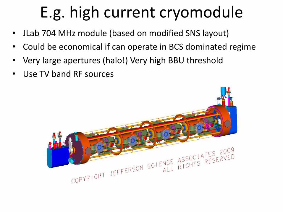
E.g. high current cryomodule • JLab 704 MHz module (based on modified SNS layout)
• Could be economical if can operate in BCS dominated regime
• Very large apertures (halo!) Very high BBU threshold
• Use TV band RF sources
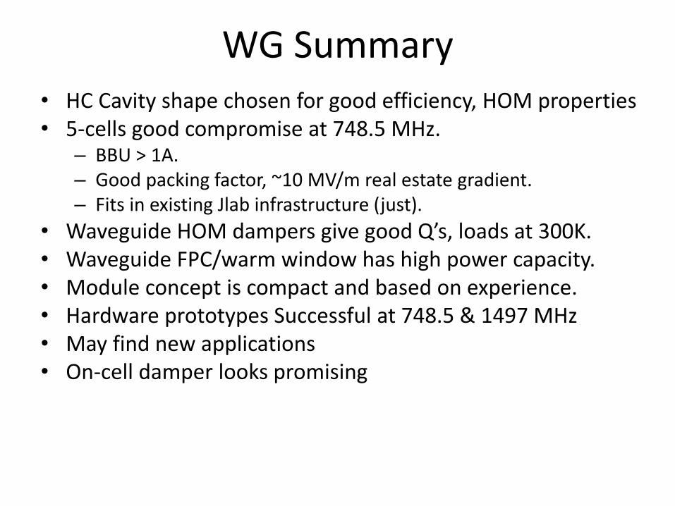
WG Summary • HC Cavity shape chosen for good efficiency, HOM properties • 5-cells good compromise at 748.5 MHz.
– BBU > 1A. – Good packing factor, ~10 MV/m real estate gradient. – Fits in existing Jlab infrastructure (just).
• Waveguide HOM dampers give good Q’s, loads at 300K. • Waveguide FPC/warm window has high power capacity. • Module concept is compact and based on experience. • Hardware prototypes Successful at 748.5 & 1497 MHz • May find new applications • On-cell damper looks promising

Discussion Effective HOM damping frequency range Cut-off to infinity Coupling to high frequency modes? Yes? Measured and/or simulated HOM Q-values for given cavity design vs.
frequency Good agreement between simulation and measurement TJNAF designs and results yes, see above Maximum HOM power handling and extraction >20 kW Estimate of the heat load to ~2K and all other intercept temperatures
at full HOM power 12 static, 64 dynamic W per cavity, ~92W at 50K. Coupling to the fundamental mode and suppression anything you want Cleanness challenges and solutions no problem Cleaning of waveguide sections standard procedures Extra beamline length required per cavity (compared to linac without
HOM damping) less than 1 cell length
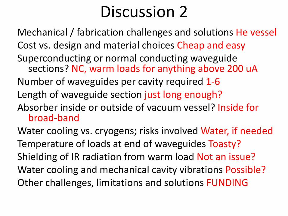
Discussion 2 Mechanical / fabrication challenges and solutions He vessel Cost vs. design and material choices Cheap and easy Superconducting or normal conducting waveguide
sections? NC, warm loads for anything above 200 uA Number of waveguides per cavity required 1-6 Length of waveguide section just long enough? Absorber inside or outside of vacuum vessel? Inside for
broad-band Water cooling vs. cryogens; risks involved Water, if needed Temperature of loads at end of waveguides Toasty? Shielding of IR radiation from warm load Not an issue? Water cooling and mechanical cavity vibrations Possible? Other challenges, limitations and solutions FUNDING

Backup material

JLAB HC Cryomodule Development Fundamental Power Coupler (FPC) One HOM waveguide steps up in size and used as FPC (does double duty)
Optimization is challenging, since He gas heats up and covers regime of laminar, transient and turbulent flow highly non-linear problem only solvable with multi-physics code (ANSYS)
Active cooling necessary (e.g. He gas trace cooling of the waveguide) Issue: Static leak and rf heat leak to 2K needs to be intercepted/minimized
ANSYS vacuum model for RF solution
trace-cool channels
NbTi helium vessel flange
AlMg serpentine seal
Nb endgroup
ANSYS He gas trace cooled FPC hardware model for thermal solution (design G. Cheng)
taper to warm rf window (no dogleg in this example)
Length of small waveguide and incorporated bumps determine the coupling factor (10mA injector (not energy recovered): Qext = 9.5e5)
Warm-to-cold transition still needs to be further optimized

Simulation of real module conditions
Log Contours

Power couplers
• Various coupler configurations are available
SNS coax coupler • Peak power in up to 550 kW (tested up to 2 MW) • 1.3 ms RF on. 60 pps • Up to 50 kW average power • Qext ~ 7 x 10 5 • 300 K window • Cooling: Inner conductor
extension: water. Inner conductor: conduction cooling. Outer conductor: GHe flow
CEBAF waveguide • Peak power up to 6
kW CW • 2K and 300 K
windows • Dogleg shields cold
window from beam.
Upgrade WG coupler • Peak power in up to 13
kW CW • 300 K window • Cooling: WG heat
stationed at 50K • Optional active cooling • Optional double warm
window
FEL high-power WG • Peak power in up to 200 kW (Window tested to 1 MW CW) • 300 K window • Cooling: Window: water.
WG transition: GHe flow • Dogleg or bend (not shown)
to avoid exposure to beam
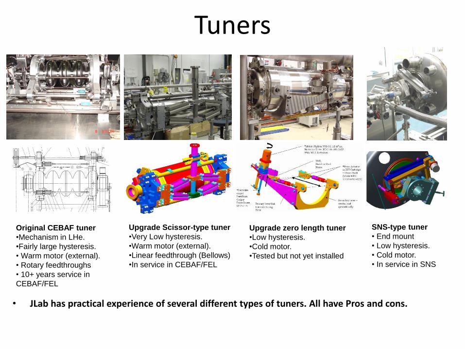
Tuners
• JLab has practical experience of several different types of tuners. All have Pros and cons.
Upgrade Scissor-type tuner
•Very Low hysteresis.
•Warm motor (external).
•Linear feedthrough (Bellows)
•In service in CEBAF/FEL
Original CEBAF tuner
•Mechanism in LHe.
•Fairly large hysteresis.
• Warm motor (external).
• Rotary feedthroughs
• 10+ years service in
CEBAF/FEL
SNS-type tuner
• End mount
• Low hysteresis.
• Cold motor.
• In service in SNS
Upgrade zero length tuner
•Low hysteresis.
•Cold motor.
•Tested but not yet installed

Ceramic window Matching at 748.5 MHz
S11 at matching frequency. Ceramic thickness 0.7007in (17.8mm) at 748.5 MHz -37dB
E fields at matching frequency WR1150 ceramic matched in 38.1mm thick iris
Matching in T model at 748.5 MHz was obtained by changing the iris height from 38.1mm to 50mm and position of the short with 10mm. S11 at matching frequency -28.5dB.
Short moved 10mm
Ceramic window Matching on T model
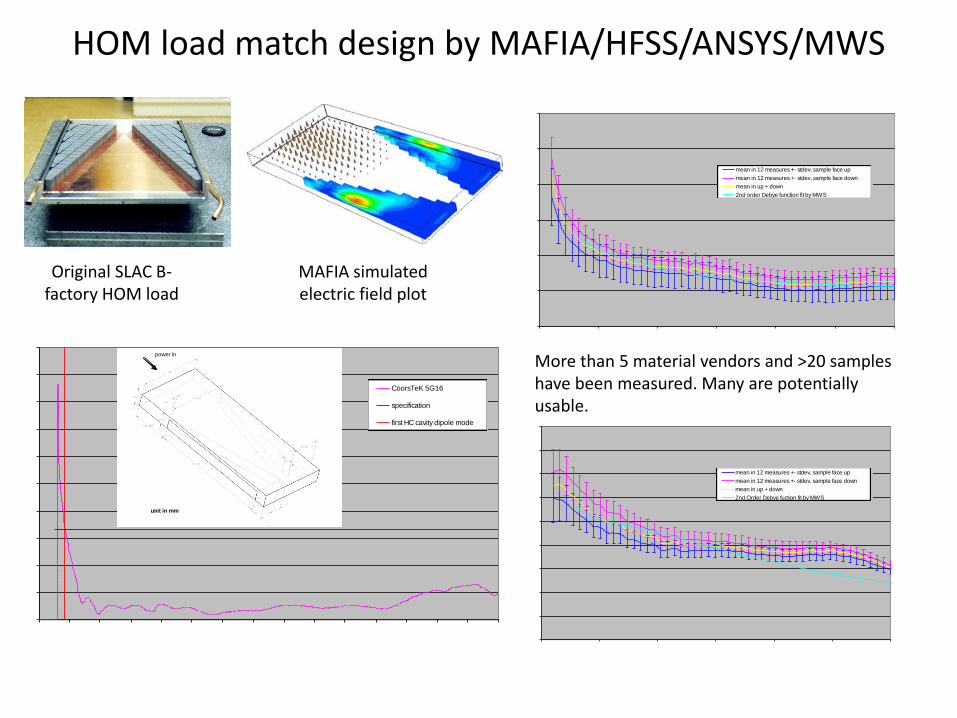
HOM load match design by MAFIA/HFSS/ANSYS/MWS
Original SLAC B-factory HOM load
MAFIA simulated electric field plot
HP87050A Measurement on Coors Tek 5G16 Sample
15
20
25
30
35
40
45
0 1 2 3 4 5 6
Frequency (Ghz)
Rela
tiv
e D
iele
ctr
ic C
on
sta
nt
mean in 12 measures +- stdev, sample face up
mean in 12 measures +- stdev, sample face down
mean in up + down
2nd order Debye function fit by MWS
HP87050A Measurement on Coors Tek 5G16 Sample
0
0.05
0.1
0.15
0.2
0.25
0.3
0.35
0.4
0.45
0 1 2 3 4 5 6
Frequency (Ghz)
Lo
ss
Tan
ge
nt
mean in 12 measures +- stdev, sample face up
mean in 12 measures +- stdev, sample face down
mean in up + down
2nd Order Debye fuction fit by MWS
MWS (Transient Solver) Simulations Design on Modified 748.5MHz Waveguide HOM Load Using Coors TeK Material
0
0.1
0.2
0.3
0.4
0.5
0.6
0.7
0.8
0.9
1
0.5 1 1.5 2 2.5 3 3.5 4 4.5 5 5.5 6 6.5 7 7.5 8
Frequency (GHz)
S1
1,
En
erg
y B
ala
nc
ed
CoorsTeK 5G16
specification
first HC cavity dipole mode
unit in mm
power in
More than 5 material vendors and >20 samples have been measured. Many are potentially usable.

Cavity broadband coupling impedance simulated using multi-beam excitation scheme
Benefit: We can distinguish between HOMs of different field nature and polarizations (monopole, dipole, quadrupole, sextupole,…)
Works with MAFIA T3 (does not work yet to our knowledge with CST Particle Studio or GdfidL)
Valuable information for high current ERLs (other than dipole modes may become important)
HOM damping efficiency is most important aspect of the HC cavity design
JLAB HC Cryomodule Development Broadband HOM Damping Efficiency
Multi-Beam Excitation Scheme (MAFIA T3)
1 beam 2 beams 3 beams
monopole dipole
horizontally polarized dipole
vertically polarized quadrupole
(normal polarization) quadrupole
(skew polarization)
mirror plan (E or M boundary) beams of charge q/n
m = beam monitors to record wake field

Aim: Investigate various HOM material candidates
JLAB HC Cryomodule Development HOM Load Material Studies VTA setup built for measurements from room temperature down to 2K
Variability of material complex properties (batch to batch and lot to lot) may be important for large scale installation
Test setup in the vertical Dewar (left), CEBAF absorber (top right) and two different wedge absorber assemblies (bottom right) made of ceramic AlN-based composites
Reflection response of different AlN-based composites measured at room temperature (r.t.) and 2 K.
Further investigations planned on different materials


![HOM Damper Hardware Considerations for Future Energy ...Figure 8 : Layout of the broadband coaxial line to dual ridge waveguide transition [13 ]. Figure 9 : Comparison of the dual](https://img.pdfslide.us/doc/110x75/60bb38b4f37f0515537907e2/hom-damper-hardware-considerations-for-future-energy-figure-8-layout-of-the.jpg)