Embed Size (px)
Citation preview
Wavefronts and Construction Tolerancesfor a Cat's-Eye Retroreflector
Reinhard Beer and Darwin Marjaniemi
A retroreflector (a device that reflects an incident beam of light through exactly 1800) constructed froma primary concave mirror and a small secondary mirror near its paraxial focus, the so-called cat's-eyeretroreflector, has been investigated. Ray-tracing of systems with both spherical and parabolic primariessuggests that the latter are considerably superior to the former and comparable to a cube-corner retro-reflector. The investigation has also enabled mechanical tolerances for the construction of a cat's-eyeretroreflector to be deduced. The predicted tolerances may be much easier to attain than those for acube-corner retroreflector.
1. Introduction
As part of this laboratory's program of the develop-ment of Fourier spectroscopy, an investigation hasbeen made of a retroreflector constructed from a con-cave primary mirror with a small secondary at itsfocus-the so-called cat's-eye retroreflector-for useas an interferometric element. Figure 1 shows asketch of such a system.
An ideal retroreflector bends all incident rays throughexactly 1800. Consequently, incident plane waves arereflected as plane waves parallel to those incident. Usecan also be made of a second property of many suchsystems: if the incident radiation is restricted to one-half of the aperture, the radiation emerges from theother half, and it can be operated upon without ob-structing the incident beam.
Retroreflectors can be constructed from three planesurfaces-the well-known cube-corner reflector-orfrom a lens with a mirror in its focal plane, or, as inthis case, from a concave mirror with a secondary atits focus. However, our interest lies in purely re-flecting systems, restricting us to either a cube-cornerreflector or a cat's-eye reflector. Both types have beenused in successful Fourier spectrometers;' but to ourknowledge, the geometrical optical properties of thecat's-eye retroreflector have never been investigated.
The obvious advantages and disadvantages of thetwo systems may be laid out this way: (1) the cat's-
Both authors were with California Institute of Technology, JetPropulsion Laboratory, Division of Space Sciences, Pasadena,California 91103 when this work was done; D. Marjaniemi ispresently with the Department of Astronomy, University ofArizona, Tucson, Arizona.
Received 3 March 1966.
eye reflector (CER) has only two elements against thethree required for a purely reflecting cube-corner re-flector (CCR); (2) intuitively, it is obvious that theCER has only one major source of misalignment-thespacing of the two elements. The CCR, on the otherhand, has six-two rotational axes for each element;(3) following directly from (1) and (2), the constructioncosts of the CCR, to interferometric standards, arelikely to be much greater than for the CER; (4) acompleted CER is probably physically much largerthan the equivalent CCR. This could create problemsin suspension and movement, since in a Fourier spectro-meter one of the elements must be moved with greatprecision; (5) the CCR, in proper adjustment, islimited only by the optical quality of its individualsurfaces and by diffraction. An otherwise perfectCER is limited by optical aberrations, the effects ofwhich are the subject of this article.
11. The ProblemBefore any meaningful computations can be per-
formed, some criterion of excellence must be established.An obvious criterion is that, assuming incident planewaves, the departures of the emergent wavefrontsfrom an arbitrary reference plane should be minimal.A second, less obvious criterion, is that the derivativeof the function describing the emergent wavefrontsshould be a minimum. This second criterion was theone actually used for the following reason: the Fourierspectrometer for which these retroreflectors have beeninvestigated employs a thick beam splitter. Conse-quently, there is a lateral shear between the two beams.If the wavefronts are plane, parallel, and normal tothe axis, there is no effect on the path difference. Onthe other hand, if the wavefronts are not plane, therewill be a variation in path difference across the aperture
July 1966 / Vol. 5, No. 7 / APPLIED OPTICS 1191
APERTURESECONDARYIREFLECTOR2APRIMARY
REFLECTORPRIMARY FOCAL LENGTH Fl
SECONDARY LIES IN FOCAL PLANE OF PRIMARY (NOMINALLY)
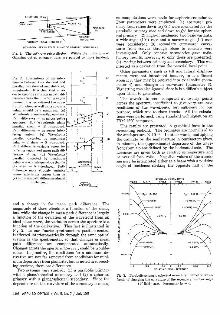
Fig. 1. The cat's-eye retroreflector. Within the limitations ofGaussian optics, emergent rays are parallel to those incident.
Fig. 2. Illustrations of the inter- (a)ference between two identical and X0parallel, but sheared and distorted,wavefronts. It is clear that in or-der to keep the variation in path dif- I lference across the interfering region i (b)
minimal, the derivative of the wave- ]front function, as well as its absolute. |value, should be a minimum. (a): XWavefronts plane parallel, no shear.: 1: d c
Path difference = x across entire - , -aperture. (b) Wavefronts plane x X1parallel, shear = S introduced.Path difference = o across inter-,fering region. (c) Wavefronts:parallel, distorted by maximum: X (d)
value = d, shear = S introduced. -
Path difference variable across in- x X2
dterfering region and mean path dif- . l lfereaice # xo. (d) Wavefronts I
parallel, distorted by maximum:value = d with steeper slope than in I INTERFERING
I REGION (c), shear = S introduced. Path: SHEAR SHEAR
difference more strongly variable l sacross interfering region than in l l(c) but mean path difference almost:
unchanged. OVERALLAPERTURE
and a change in the mean path difference. Themagnitude of these effects is a function of the shear,but, while the change in mean path difference is largelya function of the deviation of the wavefront from anideal plane wave, the variation across the aperture is afunction of the derivative. This fact is illustrated inFig. 2. In our Fourier spectrometers, position controlis effected interferometrically through the same opticalsystem as the spectrometer, so that changes in meanpath difference are compensated automatically.Changes across the aperture, however, could be trouble-some. In practice, the conditions for a minimum de-rivative are not far removed from conditions for mini-mum departures from planarity, but as noted in succeed-ing sections, there are differences.
Two systems were studied: (1) a parabolic primarywith a plane/spherical secondary and (2) a sphericalprimary with a plane/spherical secondary. Since thedependence on the curvature of the secondary is minor,
no computations were made for aspheric secondaries.Four parameters were employed-(1) aperture: pri-mary focal ratios down tof/2.5 were considered for theparabolic primary case and down tof/5 for the spher-ical primary; (2) angle of incidence: two basic variants,a wide-angle (10°) case and a narrow-angle (10) casewere considered; (3) secondary curvature: curva-tures from convex through plane to concave wereinvestigated. Only concave secondaries gave satis-factory results, however, so only these are presented;(4) spacing between primary and secondary. This wasinserted as a deviation from the paraxial focal point.
Other parameters, such as tilt and lateral displace-ments, were not introduced because, to a sufficientaccuracy, they may be resolved into axial shifts (para-meter 4) and changes in curvature (parameter 3).Vignetting was also ignored since it is a difficult subjectupon which to generalize.
The wavefronts were computed at twenty pointsacross the aperture, insufficient to give very accuraterenditions of the wavefronts, but sufficient for ourpurpose, which was to show trends. All the calcula-tions were performed, using standard techniques, on anIBM 1620 computer.
The results are presented in graphical form in thesucceeding sections. The ordinates are normalized tothe semiaperture X 10-4. In other words, multiplyingthe ordinate by the semiaperture in centimeters gives,in microns, the (approximate) departure of the wave-front from a plane defined by the horizontal axis. Theabscissae are given both as relative semiaperture andas over-all focal ratio. Negative values of the abscis-sae may be interpreted either as a beam with a positiveangle of incidence striking the opposite half of the
OVERALL FOCAL RATIOF/2.50 F/4.17 F/12.5 0 F112.5 F/4.17 F2.50
I I I I I I I I I I I I I I I I 1
+0.002 -R 2 =-2.IO5FI R2 =-2.105F, -
-2.083FI -2.083Fj
-2.062F, -2.062F,0 ~ 0.001w -2.041 F -2.041 F
I
0
z /-2.020F 1 -- -2.020FI_ /---2.000FI -2.000FI
-0.001
-1.0 -0.6 -0.2 0 +0.2 +0.6 +1.0RELATIVE SEMI-APERTURE
Fig. 3. Parabolic primary, spherical secondary. Effect on wave-fronts of changing the curvature of the secondary, narrow angle
(10 field) case. Parameter Ax = 0.
1192 APPLIED OPTICS / Vol. 5, No. 7 / July 1966
OVERALL FOCAL RATIO
0 -2.O62FI.
Id ~~~~~~~~~~~~~~R2=-2.105F,+0.1-208F
0. -2.041F1 ~ ~ ~ ~ ~ ~ 20 FI-./
-02 | I F N | 8 i ' l l l l l -2.062 1-2.041IF1
-.0 2 0 ,6 -0.2 t b +a -2.02 .F10Z C -
-2.000F
-0.1
-2 .000FI
-0.2 I ~ ~ ' -0 -0.6 -0.2 0 +0.2 +0.6 +1.0
RELATIVE SEMI-APERTURE
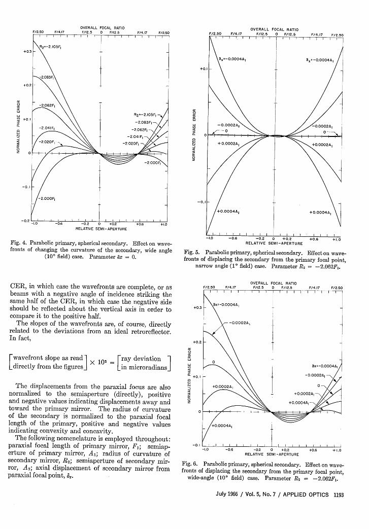
Fig. 4. Parabolic primary, spherical secondary. Effect on wave-fronts of changing the curvature of the secondary, wide angle
(100 field) case. Parameter x = 0.
CER, in which case the wavefronts are complete, or asbeams with a negative angle of incidence striking thesame half of the CER, in which case the negative sideshould be reflected about the vertical axis in order tocompare it to the positive half.
The slopes of the wavefronts are, of course, directlyrelated to the deviations from an ideal retroreflector.In fact,
Lwavefront slope as readI X 102 ray deviation 1directly from the figuresj Lin microradians]
The displacements from the paraxial focus are alsonormalized to the semiaperture (directly), positiveand negative values indicating displacements away andtoward the primary mirror. The radius of curvatureof the secondary is normalized to the paraxial focallength of the primary, positive and negative valuesindicating convexity and concavity.
The following nomenclature is employed throughout:paraxial focal length of primary mirror, F; semiap-erture of primary mirror, A; radius of curvature ofsecondary mirror, R2; semiaperture of secondary mir-ror, A2 ; axial displacement of secondary mirror fromparaxial focal point, .
OVERALL FOCAL RATIOF/12.5 0 F/12.5
/ +0.0002A +O.0002AI0~~~~~~~~~~~~~~~
-0.1
+0004A, +0.0004A,
/ I I I I I I I I I I I 1 -1.0 -0.6 -0.2 0 +0.2 +0.6 +1.0
RELATIVE SEMI-APERTURE
Fig. 5. Parabolic primary, spherical secondary. Effect on wave-fronts of displacing the secondary from the primary focal point,
narrow angle (10 field) case. Parameter R2 = -2.062FI.
OVERALL FOCAL RATIOF/2.50 F/4.17 F/12.5 0 F/12.5 F/4.17 F/2.50
I I I I l I I II I
+0.3 x= 0.0004AI _
-0.0002AI
+0.2cc0a:
/+0.0004AI l lxl=l-l .00 4A
a. +01-0.0002AI
-0.1
0
N +0.0002A, 0
+0.0002A10cc +0.0004AI
0
0O.0004A,
-0.1 I I I -1.0 -0.6 -0.2 0 +0.2 +0.6 + 1.0
RELATIVE SEMI-APERTURE
Fig. 6. Parabolic primary, spherical secondary. Effect on wave-fronts of displacing the secondary from the primary focal point,
wide-angle (10° field) case. Parameter 2 = -2.062F 1 .
July 1966 / Vol. 5, No. 7 / APPLIED OPTICS 1193
OVERALL FOCAL RATIO
cc0
cc
0
a.
0
cc0
-10 -06 -0 2 0 .0.2RELATIVE SEMI-APERTURE
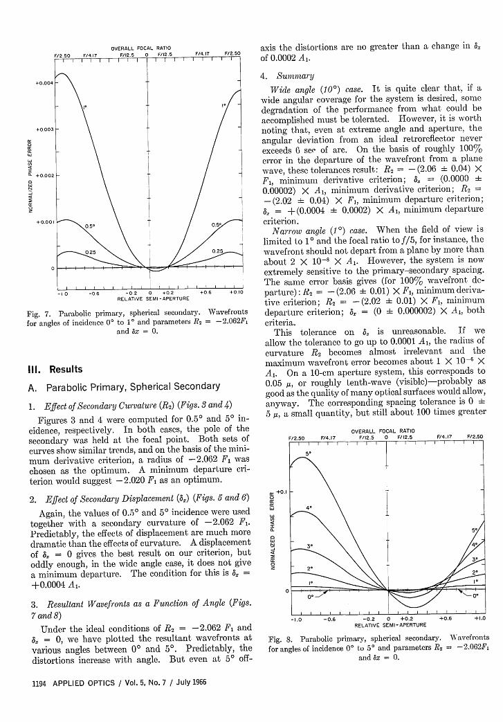
Fig. 7. Parabolic primary, spherical secondary.for angles of incidence 00 to 1 and parameters Rt
and ax = 0.
Ill. Results
A. Parabolic Primary, Spherical Secon
1. Effect of Secondary Curvature (R2) (Figs.
Figures 3 and 4 were computed for 0.5cidence, respectively. In both cases, thesecondary was held at the focal point.curves show similar trends, and on the basismum derivative criterion, a radius of -2chosen as the optimum. A minimum dterion would suggest -2.020 F1 as an opti
2. Effect of Secondary Displacement (3z) (I
Again, the values of 0.50 and 50 incidentogether with a secondary curvature ofPredictably, the effects of displacement ardramatic than the effects of curvature. A Iof A: = 0 gives the best result on our coddly enough, in the wide angle case, it ca minimum departure. The condition fol+0.0004 A,.
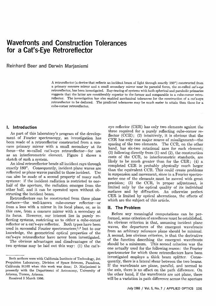
3. Resultant Wavefronts as a Function of
7 and 8)
Under the ideal conditions of R 2 = -
= 0, we have plotted the resultant Nvarious angles between 00 and 5°. Predistortions increase with angle. But ev(
/4.17 F/2.5O axis the distortions are no greater than a change in zWFFF of 0.0002 A,.
4. Summnary
IWide angle ( O) case. It is quite clear that, if a
wide angular coverage for the system is desired, somedegradation of the performance from what could beaccomplished must be tolerated. However, it is worthnoting that, even at extreme angle and aperture, theangular deviation from an ideal retroreflector neverexceeds 6 see of arc. On the basis of roughly 100%error in the departure of the wavefront from a planewave, these tolerances result: R 2 = - (2.06 i 0.04) XF1, minimum derivative criterion; = (0.0000 i
0.00002) X Al, minimum derivative criterion; R 2 =
- (2.02 i 0.04) X F1,, minimum departure criterion;= +(0.0004 -t 0.0002) X Al, minimum departure
0.50 criterion.Narrow angle (10) case. When the field of view is
limited to 10 and the focal ratio to f/5, for instance, the0.25 wavefront should not depart from a plane by more than
about 2 X 10⁻¹ X Al. However, the system is nowextremely sensitive to the primary-secondary spacing.
I I | The same error basis gives (for 100% wavefront de-+0.6 +O.IO parture): R 2 = - (2.06 i 0.01) X F1, minimum deriva-
tive criterion; R 2 = -(2.02 -4 0.01) X F1, minimumWavefronts departure criterion; ax = (0 i 0.000002) X Al, both
' = -2.062Fi criteria.This tolerance on a is unreasonable. If we
allow the tolerance to go up to 0.0001 Al, the radius ofcurvature R 2 becomes almost irrelevant and themaximum wavefront error becomes about 1 X 10⁻⁶ XAl. On a 10-cm aperture system, this corresponds to
dary 0.05 g, or roughly tenth-wave (visible)-probably asgood as the quality of many optical surfaces would allow,
3 and 4) anyway. The corresponding spacing tolerance is 0 i
° *\lrl R° an_ 5 /, a small quantity, but still about 100 times greaterIulU dj 11-
pole of theBoth sets ofof the mini-
2.062 F waseparture cri-mum.
'igs. 5 and 6)
ce were used-2.062 Fl.
e much moredisplacementriterion, butloes not giver this is 6 =
Angle (Figs.
2.062 F andravefronts atdictably, thetn at 5 off-
F/2.50 F/4.17
it +0.1
ccc:0.
as
I
N
0
OVERALL FOCAL RATIOF/12.5 0 F/12.5 F/4.17 F/2.50
-1.0 -0.6 -0.2 0 +0.2 +0.6 +1.0RELATIVE SEMI-APERTURE
Fig. 8. Parabolic primary, spherical secondary. Wavefrontsfor angles of incidence 00 to 50 and parameters R 2 = -2.062F 1
and ax = 0.
1194 APPLIED OPTICS / Vol. 5, No. 7 / July 1966
than the tolerances on each of the six axes of theequivalent cube-corner reflector.
B. Spherical Primary, Spherical Secondary
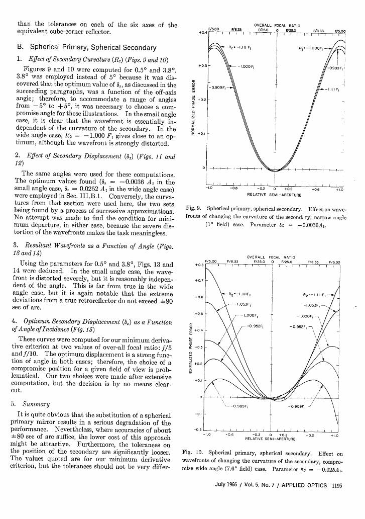
1. Effect of Secondary Curvature (R2) (Figs. 9 and 10)Figures 9 and 10 were computed for 0.50 and 3.8°.
3.8O was employed instead of 5 because it was dis-covered that the optimum value of 6,, as discussed in thesucceeding paragraphs, was a function of the off-axisangle; therefore, to accommodate a range of anglesfrom -5° to +50, it was necessary to choose a com-promise angle for these illustrations. In the small anglecase, it is clear that the wavefront is essentially in-dependent of the curvature of the secondary. In thewide angle case, 2 = - 1.000 F gives close to an op-timum, although the wavefront is strongly distorted.
2. Effect of Secondary Displacement (%) (Figs. 1 i and12)
The same angles were used for these computations.The optimum values found ( = -0.0036 A in thesmall angle case, 8 = 0.0252 A in the wide angle case)were employed in Sec. III.B.1. Conversely, the curva-tures from that section were used here, the two setsbeing found by a process of successive approximations.No attempt was made to find the condition for mini-mum departure, in either case, because the severe dis-tortion of the wavefronts makes the task meaningless.
3. Resultant Wavefronts as a Function of Angle (Figs.13 and 14)
Using the parameters for 0.50 and 3.80, Figs. 13 and14 were deduced. In the small angle case, the wave-front is distorted severely, but it is reasonably indepen-dent of the angle. This is far from true in the wideangle case, but it is again notable that the extremedeviations from a true retroreflector do not exceed ±480see of arc.
4. Optimum Secondary Displacement () as a Functionof Angle of Incidence (Fig. 15)
These curves were computed for our minimum deriva-tive criterion at two values of over-all focal ratio: f/5and f/10. The optimum displacement is a strong func-tion of angle in both cases; therefore, the choice of acompromise position for a given field of view is prob-lematical. Our two choices were made after extensivecomputation, but the decision is by no means clear-cut.
5. Summary
It is quite obvious that the substitution of a sphericalprimary mirror results in a serious degradation of theperformance. Nevertheless, where accuracies of about±480 see of arc suffice, the lower cost of this approachmight be attractive. Furthermore, the tolerances onthe position of the secondary are significantly looser.The values quoted are for our minimum derivativecriterion, but the tolerances should not be very differ-
OVERALL FOCAL RATIO
cc0cccc
0
4:cc0
-0.2 0 +0.2RELATIVE SEMI-APERTURE
Fig. 9. Spherical primary, spherical secondary. Effect on wave-fronts of changing the curvature of the secondary, narrow angle
(10 field) case. Parameter ax = -. 0036A,.
OVERALL FOCAL RATIOF/25.0 0 F/25.0
+0.8
+0.7
+0.6
+0.5
0
cc +0.Acr
oa: +03
s4 +0.2
0
+0.2
-0.1
-0.2-1.0 -0.6 -0.2 0 +0.2 +0.2 +1.0
RELATIVE SEMI-APERTURE
Fig. 10. Spherical primary, spherical secondary. Effect onwavefronts of changing the curvature of the secondary, compro-mise wide angle (7.60 field) case. Parameter x = -0.025Aj.
July 1966 Vol. 5, No. 7 / APPLIED OPTICS 1195
OVERALL FOCAL RATIOOVERALL FOCAL RATIO
0
cc +1.0
00 A -.00056Al
0 -00036A 1
o -0.0016A
-10 0.06A I+0.0164A, - 1.0
1.0 -0.6 -0.2 0 +0.2 +0.6 +1.0RELATIVE SEMI-APERTURE
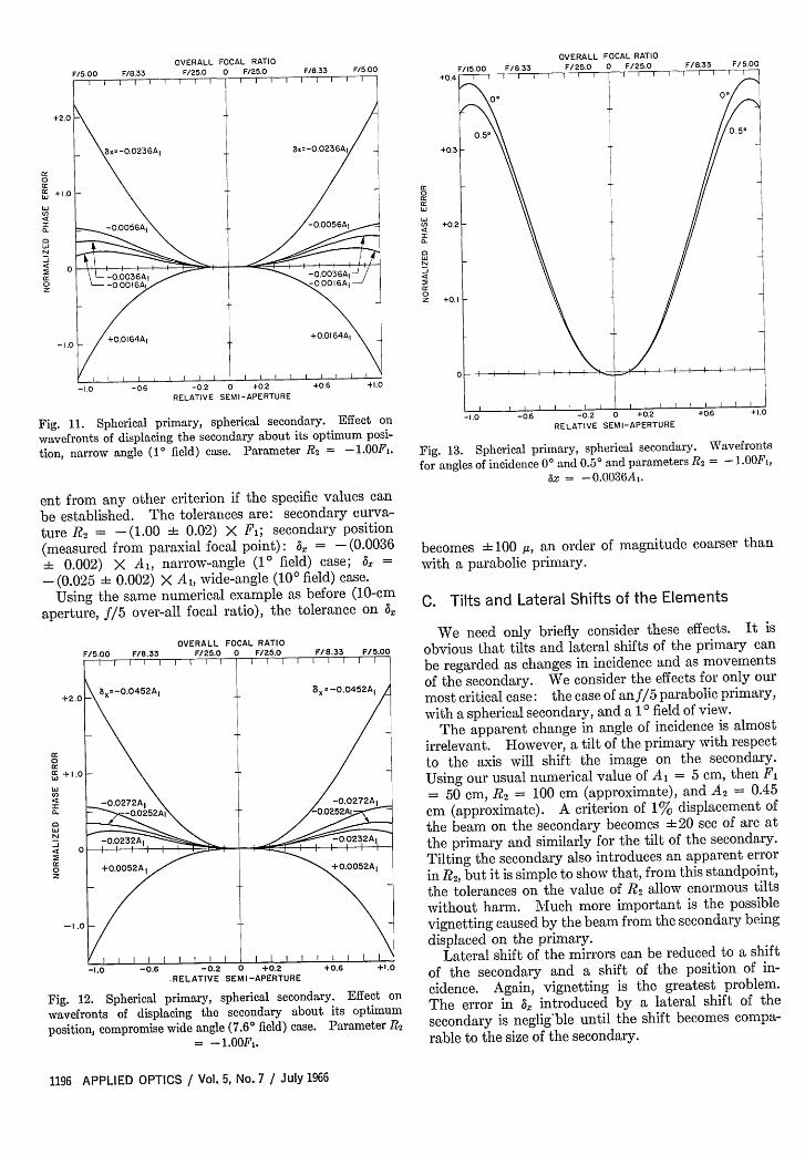
Fig. 11. Spherical primary, spherical secondary. Effect on
wavefronts of displacing the secondary about its optimum posi-
tion, narrow angle (10 field) case. Parameter R2 = -1.00F 1 .
ent from any other criterion if the specific values can
be established. The tolerances are: secondary curva-ture R2 = - (1.00 ± 0.02) X Fj; secondary position(measured from paraxial focal point): Ax = - (0.0036± 0.002) X A,, narrow-angle (10 field) case; a =
-(0.025 ±4 0.002) X Al, wide-angle (100 field) case.Using the same numerical example as before (10-cm
aperture, f/5 over-all focal ratio), the tolerance on 3,
OVERALL FOCAL RATIOF/5.00 F/8.33 F/25.0 0 F/25.0 F/8.33 F/5.00
I I I I I I I I 1
+2.0 X =-0.0452A, 81
= -0.0452A
0
cc + 1.0
cc -O.0272A -0.0272A 1
0
N
0-O.22I-O03A
o +0.0052A +0.0052AI
-1.0
/ I I I I I I I I I I I I I I I I
-1.0 -0.6 -0.2 0 +0.2 +0.6 +1.0RELATIVE SEMI-APERTURE
Fig. 12. Spherical primary, spherical secondary. Effect on
wavefronts of displacing the secondary about its optimum
position, compromise wide angle (7.60 field) case. Parameter R2
=- 1.00F1 .
cc II > 4
0 l
+0.2
0
RELATIVE SEMI-APERTURE
Fig. 13. Spherical primary, spherical secondary. Wavefronts
for angles of incidence 0° and 0.5° and parameters R2 -.001,ax = -0.+036A0.
becomes 4 100 ,u, an order of magnitude coarser thanwith a parabolic primary.
C. Tilts and Lateral Shifts of the Elements
We need only briefly consider these effects. It isobvious that tilts and lateral shifts of the primary canbe regarded as changes in incidence and as movementsof the secondary. We consider the effects for only ourmost critical case: the case of anf/5 parabolic primary,with a spherical secondary, and a 10 field of view.
The apparent change in angle of incidence is almostirrelevant. However, a tilt of the primary with respectto the axis will shift the image on the secondary.Using our usual numerical value of A1 = 5 cm, then F
= 50 cm, R2 = 100 cm (approximate), and A2 = 0.45cm (approximate). A criterion of 17 displacement ofthe beam on the secondary becomes ±20 see of arc atthe primary and similarly for the tilt of the secondary.Tilting the secondary also introduces an apparent errorin R2, but it is simple to show that, from this standpoint,the tolerances on the value of R 2 allow enormous tiltswithout harm. Much more important is the possiblevignetting caused by the beam from the secondary beingdisplaced on the primary.
Lateral shift of the mirrors can be reduced to a shiftof the secondary and a shift of the position of in-cidence. Again, vignetting is the greatest problem.The error in 5, introduced by a lateral shift of thesecondary is neglig ble until the shift becomes compa-
rable to the size of the secondary.
1196 APPLIED OPTICS / Vol. 5, No. 7 / July 1966
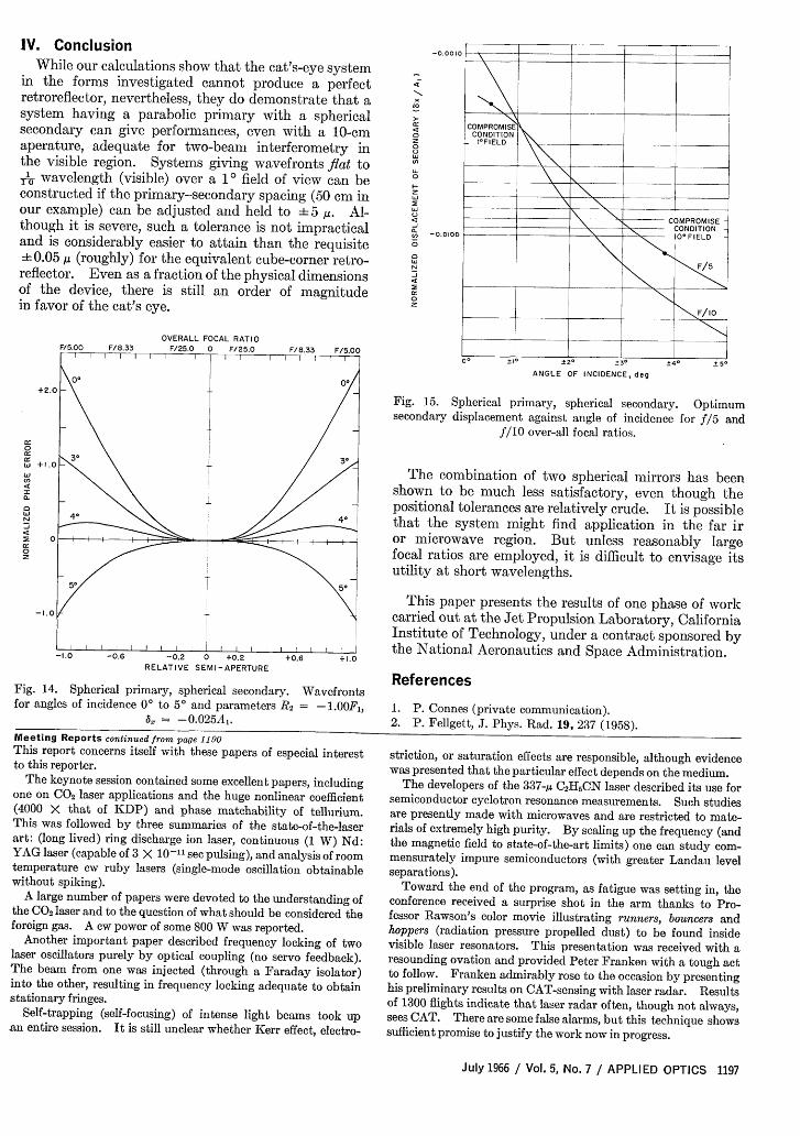
IV. ConclusionWhile our calculations show that the cat's-eye system
in the forms investigated cannot produce a perfectretroreflector, nevertheless, they do demonstrate that asystem having a parabolic primary with a sphericalsecondary can give performances, even with a 10-cmaperature, adequate for two-beam interferometry inthe visible region. Systems giving wavefronts flat to1T wavelength (visible) over a 1 field of view can beconstructed if the primary-secondary spacing (50 cm inour example) can be adjusted and held to 5 . Al-though it is severe, such a tolerance is not impracticaland is considerably easier to attain than the requisite± 0.05 ,u (roughly) for the equivalent cube-corner retro-reflector. Even as a fraction of the physical dimensionsof the device, there is still an order of magnitudein favor of the cat's eye.
OVERALL FOCAL RATIOF/25.0 0 F/25.0
+2.0
0
W +1.1
4In
-
a:
0
0
-1.0
-0.2 0 +0.2 +0.6 +1.0RELATIVE SEMI-APERTURE
Fig. 14. Spherical primary, spherical secondary. Wavefrontsfor angles of incidence 0 to 5 and parameters R2 = -1.00F1,
a = -. 025A.Meeting Reports continued from page 1190This report concerns itself with these papers of especial interestto this reporter.
The keynote session contained some excellent papers, includingone on C02 laser applications and the huge nonlinear coefficient(4000 X that of KDP) and phase matchability of tellurium.This was followed by three summaries of the state-of-the-laserart: (long lived) ring discharge ion laser, continuous (1 W) Nd:YAG laser (capable of 3 X 10-11 sec pulsing), and analysis of roomtemperature cw ruby lasers (single-mode oscillation obtainablewithout spiking).
A large number of papers were devoted to the understanding ofthe C02 laser and to the question of what should be considered theforeign gas. A cw power of some 800 W was reported.
Another important paper described frequency locking of twolaser oscillators purely by optical coupling (no servo feedback).The beam from one was injected (through a Faraday isolator)into the other, resulting in frequency locking adequate to obtainstationary fringes.
Self-trapping (self-focusing) of intense light beams took upan entire session. It is still unclear whether Kerr effect, electro-
-0.0010
z0
z
-0.01 00
ANGLE OF INCIDENCE, deg
Fig. 15. Spherical primary, spherical secondary. Optimumsecondary displacement against angle of incidence for f5 and
f/10 over-all focal ratios.
The combination of two spherical mirrors has beenshown to be much less satisfactory, even though thepositional tolerances are relatively crude. It is possiblethat the system might find application in the far iror microwave region. But unless reasonably largefocal ratios are employed, it is difficult to envisage itsutility at short wavelengths.
This paper presents the results of one phase of workcarried out at the Jet Propulsion Laboratory, CaliforniaInstitute of Technology, under a contract sponsored bythe National Aeronautics and Space Administration.
References
1. P. Connes (private communication).2. P. Fellgett, J. Phys. Rad. 19, 237 (1958).
striation, or saturation effects are responsible, although evidencewas presented that the particular effect depends on the medium.
The developers of the 337- C2H5CN laser described its use forsemiconductor cyclotron resonance measurements. Such studiesare presently made with microwaves and are restricted to mate-rials of extremely high purity. By scaling up the frequency (andthe magnetic field to state-of-the-art limits) one can study com-mensurately impure semiconductors (with greater Landau levelseparations).
Toward the end of the program, as fatigue was setting in, theconference received a surprise shot in the arm thanks to Pro-fessor Rawson's color movie illustrating runners, bouncers andhoppers (radiation pressure propelled dust) to be found insidevisible laser resonators. This presentation was received with aresounding ovation and provided Peter Franken with a tough actto follow. Franken admirably rose to the occasion by presentinghis preliminary results on CAT-sensing with laser radar. Resultsof 1300 flights indicate that laser radar often, though not always,sees CAT. There are some false alarms, but this technique showssufficient promise to justify the work now in progress.
July 1966 / Vol. 5, No. 7 / APPLIED OPTICS 1197
Ring modes in ion lasers (also seen under high current density
and transient conditions) were described in a paper concluding
that these are probably caused by large radial variation in
gain.Enhanced total internal reflection described the operation of
fiber lasers comprised of an unamplifying, high-index glass core,
surrounded by a low-index (not necessarily homogeneous) Nd-
doped cladding. Nearly all the light emerged from the core,
indicating internal reflectivities greater than 100%.Work on pulsed laser holography was reported showing how
interferometry applications can be extended to the realm of tran-
sient phenomena, and how to use a diffusing screen to improvespatial matching.
Finally, a post deadline paper described how the Naval Re-
search Laboratory plasma section dumped virtually all of 250 J
into a tiny tube of pure nitrogen in 3 nsec to obtain a MW laserpulse at 3371 A.
A program of the meeting appeared in IEEE Journal of Quan-
tum Electronics QE-2, No. 4, April (1966), and it is planned to
publish the conference papers in a future issue of that journal.
Sixth Conference on Applied Meteorology (Aero-space Meteorology) of the American Meteorologi-cal Society with American Institute of Aeronauticsand Astronautics 28-31 March, 1966, Los Angeles,
CaliforniaReported by D. E. Burch,
Philco Corporation-Aeronutronic Division
The Conference was held at the beautiful Statler Hilton Hotel with
more than 300 registrants, and approximately 70 papers were pre-
sented with double sessions during 1- days of the 3- day meet-
ing. This suggests that the Conference has already passed its op-
timum size. In general, it appeared that sufficient time was al-
lowed for the presentation of the papers and for discussion.
As one who had not attended any of the previous meetings of
this group, the writer was interested in finding out the types of
problems being dealt with by meteorologists these days. As in
most fields of science and engineering, the influence of the space
age is being felt strongly. The increasing role of the meteorologist
is indicated by the requirements for data which were regarded as
unimportant a few years ago, but are now desperately needed by
designers of aerospace vehicles and instruments. As an example,
designers of supersonic aircraft need answers to many questions
regarding clear air turbulence. Meteorologists are trying to deter-
mine what causes it, how bad it is, where and how often it occurs,
and how to detect it in time for an aircraft to avoid it. The im-
portance of the problem is indicated by the title of one of the pa-
pers: High Altitude Clear Air Turbulence-(HICAT)-Menaceto the Aerial Highway.
One session dealt with Atmospheric Pollution Due to Aerospace
Operations. Problems considered included the diffusion of toxic
gases from rocket exhausts and of ablation particles. Although
there was no session dealing with smog-a problem of air pollu-
tion more important to many of the local residents-it was the
one most talked about in the halls. Visitors from other parts of
the country learned the meaning of a word understood best by
residents of the Los Angeles area: smog-alert. In spite of a smog
content described locally as causing "moderate to heavy eye ir-
ritation", the visitors enjoyed some warm, sunny weather.
Approximately ten exhibitors displayed a variety of instru-
ments, some of which are quite sophisticated, incorporatingmany of the advancements in data recording, analysis, and dis-
play. Modern digitalizing techniques have been adapted to re-
cording of such basic meteorological quantities as rainfall, wind
velocity, temperature, etc. Great progress has also been made
in the methods of relaying weather data from one station to an-
other and in the methods of displaying them.There was no official banquet, but a Sipposium was held with
cocktails available at popular prices. Apparently the AMS is
not blessed, as is the OSA, with the luxury of prosperous ex-
hibitors who are willing to provide free cocktails.
Fiftieth Anniversary Meeting of theOptical Society of America, 15-18March 1966, Washington, D.C.
Reported by L. F. Drummeter, Jr., Naval Research Laboratory
The Fiftieth Anniversary Meeting Program of the Optical Societyof America was large, inspired, and frustrating. It set a record
in number of days-four-in registration-1300-and probably inthe number of papers presented. It had an inspired exhibit and
program. It was frustrating for one person to attempt to be in
three places simultaneously; it was frustrating that some of the
invited papers never quite jelled; and it was frustrating that someof the meeting mechanics were arranged awkwardly.
The exhibit of historical optical equipment interlaced with
tutorial photographic essays on technical subjects was the most
fascinating and delightful exhibit that I have seen. Judgingfrom the attendance and overheard remarks, many of the other
attendees experienced similar feelings. I particularly enjoyedJohn Strong's arrangement to pack up the Rowland ruling engineplus Wilbur Perry and have them both functioning at the
exhibit. Other memorabilia that appealed to me included a 1789
Achromat, the 1907 NBS Fabry-Perot used by Priest, Barne's1934 wire diffraction grating, the Zeiss exhibit of microscopes
ranging back to a seventeenth-century glass and including the
famous 1920 scope, and Lyman's vacuum tiv spectrograph.Continued on page 1202
photo Mitchell Valentine
The Foreign Secretary of the Royal Society of London: H. W.Thompson Oxford.
1198 APPLIED OPTICS / Vol. 5, No. 7 / July 1966