Embed Size (px)
Citation preview
WaveAce 1000/2000 Remote Control Command Reference
700 Chestnut Ridge Road Chestnut Ridge, NY, 10977-6499 Tel: (845) 425-2000, Fax: (845) 578 5985 teledynelecroy.com
WaveAce 1000/2000 Remote Control Operator's Manual © 2017 Teledyne LeCroy, Inc. All rights reserved.
WaveAce is a registered trademark of Teledyne LeCroy, Inc.
Teledyne LeCroy and other product or brand names are trademarks or requested trademarks of their respective holders. Information in this publication supersedes all earlier versions. Specifications are subject to change without notice.
920836 Rev C January 2017
Operator's Manual
i
TABLE OF CONTENTS Part I: Introduction to Remote Control ........................................................................................................ 3
About This Manual ................................................................................................................................... 3 About Remote Control ............................................................................................................................. 3 Remote Control Through USB .................................................................................................................. 4 Remote Control Through LAN .................................................................................................................. 5 Program Messages ................................................................................................................................... 6 Response Messages.................................................................................................................................. 9 Using Status Registers ............................................................................................................................ 10 Commands and Queries by Subsystem .................................................................................................. 12 Commands and Queries by Name (Alphabetical) .................................................................................. 15
Part II: Command Reference ...................................................................................................................... 17 Command Notation ................................................................................................................................ 17 ACQUISITION - *TRG............................................................................................................................... 18 ACQUISITION - ARM_ACQUISITION, ARM .............................................................................................. 18 ACQUISITION - AUTO_SETUP, ASET........................................................................................................ 18 ACQUISITION – ACQUIRE_WAY, ACQW ................................................................................................. 19 ACQUISITION - ATTENUATION, ATTN ..................................................................................................... 20 ACQUISITION - BANDWIDTH_LIMIT, BWL .............................................................................................. 21 ACQUISITION - COUPLING, CPL .............................................................................................................. 22 ACQUISITION - FILTER, FILT .................................................................................................................... 23 ACQUISITION – FILT_SET, FILTS .............................................................................................................. 24 ACQUISITION - FORCE_TRIGGER, FRTR .................................................................................................. 25 ACQUISITION - INTERLEAVED, ILVD ........................................................................................................ 25 ACQUISITION - OFFSET, OFST ................................................................................................................. 26 ACQUISITION – PEAK_DETECT, PDET ..................................................................................................... 27 ACQUISITION - STOP ............................................................................................................................... 27 ACQUISITION - TIME_DIV, TDIV .............................................................................................................. 28 ACQUISITION - TRIG_COUPLING, TRCP .................................................................................................. 29 ACQUISITION - TRIG_DELAY, TRDL ......................................................................................................... 30 ACQUISITION - TRIG_LEVEL, TRLV .......................................................................................................... 31 ACQUISITION - TRIG_MODE, TRMD ....................................................................................................... 32 ACQUISITION - TRIG_SELECT, TRSE ........................................................................................................ 33 ACQUISITION - TRIG_SLOPE, TRSL .......................................................................................................... 34 ACQUISITION - VOLT_DIV, VDIV ............................................................................................................. 35 ACQUISITION - WAIT .............................................................................................................................. 36 CURSOR - CURSOR_MEASURE, CRMS .................................................................................................... 37 CURSOR - CURSOR_SET, CRST ................................................................................................................ 38 CURSOR - CURSOR_VALUE?, CRVA? ....................................................................................................... 39 CURSOR - PARAMETER_CUSTOM, PACU ................................................................................................ 40

WaveAce Remote Control
ii 920836 Rev C
CURSOR - PARAMETER_VALUE?, PAVA? ................................................................................................ 42 DISPLAY - DOT_JOIN, DTJN ..................................................................................................................... 44 DISPLAY - HOR_MAGNIFY, HMAG .......................................................................................................... 45 DISPLAY - HOR_POSITION, HPOS ............................................................................................................ 46 DISPLAY - INTENSITY, INTS ...................................................................................................................... 47 DISPLAY - INVERTSET, INVS .................................................................................................................... 47 DISPLAY - PERSIST, PERS ......................................................................................................................... 48 DISPLAY - PERSIST_SETUP, PESU ............................................................................................................ 49 DISPLAY – SCREEN SAVE, SCSV ............................................................................................................... 50 DISPLAY - TRACE, TRA ............................................................................................................................. 51 MISCELLANEOUS - *CAL? ....................................................................................................................... 52 MISCELLANEOUS - *IDN? ....................................................................................................................... 52 MISCELLANEOUS – AUTO-CALIBRATE, ACAL .......................................................................................... 53 MISCELLANEOUS - BUZZER, BUZZ .......................................................................................................... 53 MISCELLANEOUS - COMM_HEADER, CHDR ........................................................................................... 54 MISCELLANEOUS - DEFINE, DEF ............................................................................................................. 55 MISCELLANEOUS - DELETE_FILE, DELF ................................................................................................... 56 MISCELLANEOUS - DIRECTORY, DIR ....................................................................................................... 56 MISCELLANEOUS – FILENAME, FLNM..................................................................................................... 57 SAVE/RECALL SETUP - *RCL .................................................................................................................... 58 SAVE/RECALL SETUP - *RST .................................................................................................................... 58 SAVE/RECALL SETUP - *SAV ................................................................................................................... 59 SAVE/RECALL SETUP - RECALL_PANEL, RCPN ......................................................................................... 59 STATUS - *CLS ......................................................................................................................................... 60 STATUS - *ESE ......................................................................................................................................... 60 STATUS - *ESR? ....................................................................................................................................... 61 STATUS - *OPC........................................................................................................................................ 62 STATUS - ALL_STATUS?, ALST? ............................................................................................................... 63 STATUS - CMR? ....................................................................................................................................... 64 STATUS - DDR? ....................................................................................................................................... 65 STATUS - EXR? ........................................................................................................................................ 66 STATUS - INR? ......................................................................................................................................... 68 WAVEFORM TRANSFER - STORE, STO .................................................................................................... 69 WAVEFORM TRANSFER - WAVEFORM, WF ............................................................................................ 69 WAVEFORM TRANSFER – WAVEFORM_SETUP, WFSU .......................................................................... 71
Appendix: Waveform Template ................................................................................................................ 72 Wave Descriptor Block WAVEDESC; Explanation ................................................................................... 72 Oscilloscope's TMPL? Query Response .................................................................................................. 88 Decoding Floating Point Numbers .......................................................................................................... 92

Operator's Manual
3
Part I: Introduction to Remote Control
About This Manual This manual includes a complete list of the command you’ll need to perform most WaveAce® 1000 and 2000 operations remotely.
Part I is an introduction to remote control and remote command syntax.
Part II lists all supported command headers with valid data parameters and values.
About Remote Control WaveAce 1000 and 2000 series oscilloscopes can be controlled remotely through a USBTMC or TCP/IP (LAN) interface. USB control is a standard feature on all WaveAce devices; TCP/IP control is standard on WaveAce 2000 devices only.
Remote control is accomplished through the exchange of program messages between the oscilloscope and a controller computer using the selected interface. The USBTMC interface utilizes standard IEEE 488.1 and IEEE 488.2 (GPIB) messages. The TCP/IP interface utilizes Teledyne LeCroy's VICP protocol, which emulates IEEE 488.2 and includes standard operation bits in a header defined by the VICP protocol.
All program messages exchanged between the scope and the controller must be formatted according to these protocols.
See Program Messages (on page 6) for more information about constructing commands and queries for control programs. The supported commands are listed in Commands and Queries by Subsystem (on page 12) and Command and Queries by Name (Alphabetical) (on page 15), and are detailed in the Command Reference section of this manual.
The free WaveStudio software can be used as a remote control terminal allowing you to send commands from a remote PC that is connected to the WaveAce by LAN or USB. Download WaveStudio from teledynelecroy.com/support/softwaredownload under Oscilloscope Downloads > Software Utilities.
WaveAce Remote Control
4 920836 Rev C
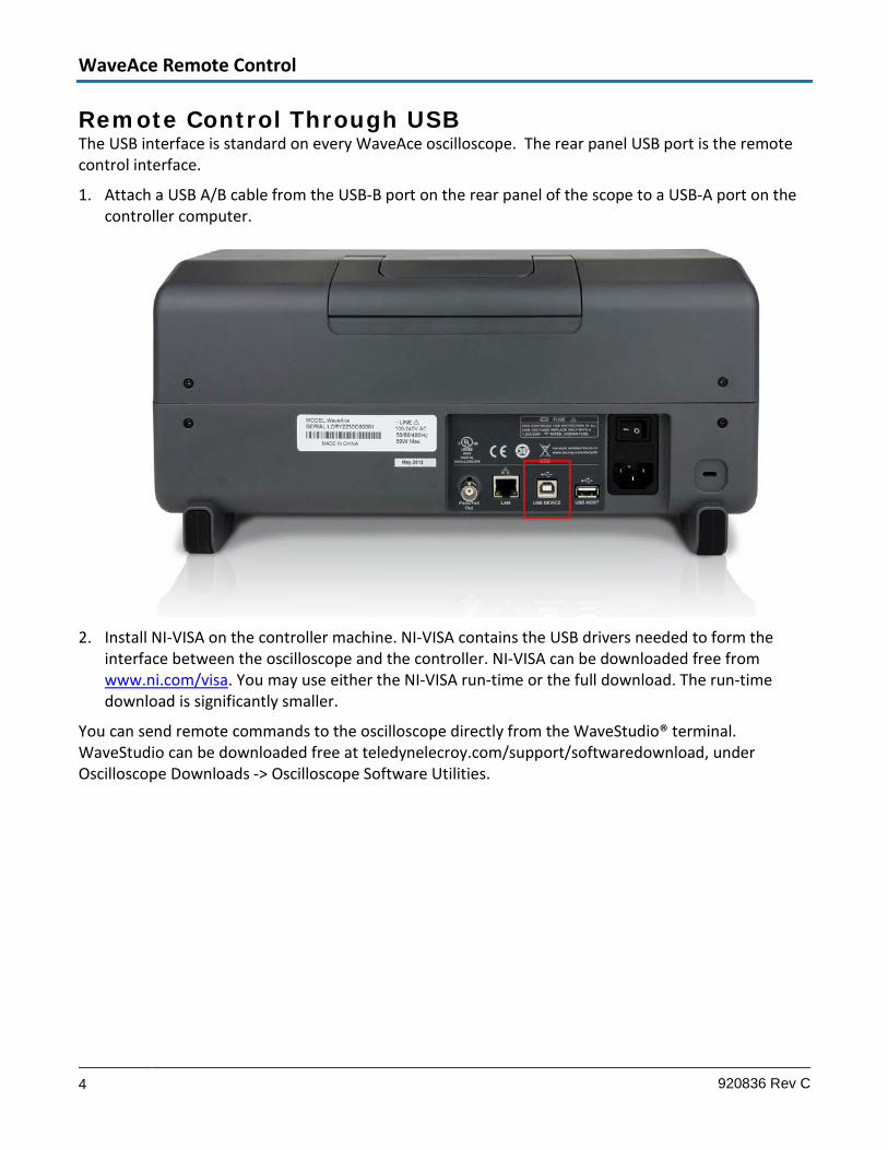
Remote Control Through USB The USB interface is standard on every WaveAce oscilloscope. The rear panel USB port is the remote control interface.
1. Attach a USB A/B cable from the USB-B port on the rear panel of the scope to a USB-A port on the controller computer.
2. Install NI-VISA on the controller machine. NI-VISA contains the USB drivers needed to form the
interface between the oscilloscope and the controller. NI-VISA can be downloaded free from www.ni.com/visa. You may use either the NI-VISA run-time or the full download. The run-time download is significantly smaller.
You can send remote commands to the oscilloscope directly from the WaveStudio® terminal. WaveStudio can be downloaded free at teledynelecroy.com/support/softwaredownload, under Oscilloscope Downloads -> Oscilloscope Software Utilities.
Operator's Manual
5
Remote Control Through LAN WaveAce 2000 series oscilloscopes have a standard LAN connection port for remote control that utilizes Teledyne LeCroy's VICP protocol for transmitting messages. This protocol emulates IEEE 488.2 (GPIB) and includes operation bits corresponding to SRQ, EOI, Clear, and others in a header that is defined by the VICP protocol.
The WaveAce must be assigned a static IPv4 address for remote control; do not use an address from the DHCP pool.
You can send remote commands to the oscilloscope directly from the WaveStudio® terminal. WaveStudio can be downloaded free at teledynelecroy.com/support/softwaredownload, under Oscilloscope Software Utilities.
On the Controller For communication using the VICP (LAN) interface, no additional driver software is required when using WaveStudio. For VICP communication with other applications that use the VISA standard, NI-VISA must be installed, along with Teledyne LeCroy's 'VICP Passport'. The Passport extends VISA to support Teledyne LeCroy's VICP protocol. The VICP passport may be downloaded from teledynelecroy.com. Also see the application brief LAB_WM827 Understanding VICP and the VICP Passport on Teledyne LeCroy's website for more information.
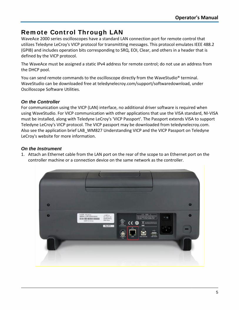
On the Instrument 1. Attach an Ethernet cable from the LAN port on the rear of the scope to an Ethernet port on the
controller machine or a connection device on the same network as the controller.

WaveAce Remote Control
6 920836 Rev C
2. Press the Utility button, then Next Page to page 3 of 4, then the IP Setting button.
3. Enter an IP Address, Subnet Mask, and Gate Way. To enter values:
• Press the Adjust knob to jump to the next segment, turn Adjust to raise/lower the value.
• Press the top soft key to jump to the next field.
NOTE: Leave DHCP field set to disabled.
Program Messages Program messages are composed of commands or queries separated by semicolons and ending with a terminator:
<command/query>; . . . . . ;<command/query> <terminator>
Command/Query Syntax The general form of a command or a query is an optional header path, followed by a command header, optionally followed by one or several parameters (shown as <data> in the following construct):
[header_path:]<header>[?] [<data>,...,<data>]
NOTE:
There is a space between the header and the first parameter.
Commas separate parameters.
The question mark [?] is optional and turns the command into a query.
The oscilloscope does not distinguish between upper- and lowercase characters. Commands/queries are shown mixed-case in this manual to call out the short form within the long form.

Operator's Manual
7
Header path Commands or queries that apply to a subsection of the oscilloscope, such as a single input channel, must have their headers prefixed with a path name indicating the channel or trace recipient of the command. It's recommended to always use header paths to minimize the risk of error if the command order changes.
The header path normally consists of an abbreviated path name followed by a colon ( : ) immediately preceding the command header.
C1:OFST -300 MV
The target waveform trace is specified using the following header path names:
Header Path Name Oscilloscope Reference
C1, C2 Channels 1 and 2
C3, C4 Channels 3 and 4 (on four-channel models)
M1,M2,M3,M4,M5,M6,M7,M8,M9,M10 Memory Units 1 through 10
TA, TB, TC, TD FFT of the corresponding Channel 1-4; in some commands also used to refer to zooms.
EX, EX5 External trigger
LINE LINE source for trigger
NOTE: Header paths TA-TD are used only to refer to the FFT of the channel, or in some cases to zoom traces.
Header paths need only be specified once until the path changes. Subsequent commands without header paths are assumed to refer to the most recently defined path:
C2:VDIV?;C2:OFST? is equivalent to C2:VDIV?;OFST?
Header The header is the mnemonic form of the operation to be performed by the oscilloscope. Most headers have a more easily recognized long form and a short form for better transfer and decoding speed. The two can be used interchangeably:
TRIG_MODE AUTO is equivalent to TRMD AUTO
Some command or query mnemonics are imposed by the IEEE 488.2 standard. All these mnemonics begin with an asterisk *.
WaveAce Remote Control
8 920836 Rev C
Data Parameters When a command uses additional data values, they are expressed as ASCII data that can take the form of character, numeric, string, or block data. Macro parameters are not implemented.
An exception is the transfer of waveforms with the WAVEFORM command/query, where the waveform is expressed as a sequence of binary data values.
Character Data These are simple alphanumeric words or abbreviations indicating a specific action.
In commands where you can specify many parameters, or where not all parameters are applicable at the same time, the format requires pairs of character data values. The first value names the parameter to be modified, while the second gives its value.
HARDCOPY_SETUP DEST,PRINTER,PRINTER,EPSON
Here, two pairs are shown: the first specifies the DESTination is a PRINTER, while the second specifies the PRINTER is EPSON. Any HARDCOPY_SETUP parameters that are not relevant for printers, or are left unchanged, are omitted from the command.
Numeric Data The numeric data type is used to enter quantitative information. Numbers can be entered as integers, fractions, or exponents: C1:VPOS -5 C2:OFST 3.56 TDIV 5.0E-6
Numeric units can be preceded with multipliers modifying the value of the expression. The following mnemonics are recognized:
Multiplier Exponential Notation Suffix
EX 1E18 Exa-
T 1E12 Tera-
MA 1E6 Mega-
M 1E-3 milli-
N 1E-9 nano-
F 1E-15 femto-
PE 1E15 Peta-
G 1E9 Giga-
K 1E3 kilo-
U 1E-6 micro-
P 1E-12 pico-
A 1E-18 atto-
Operator's Manual
9
String Data This is used to send multiple characters as a single parameter. Enclose any sequence of ASCII characters between single or double quotation marks: DIRectory DISK,UDSK,ACTION,CREATE,'20120801Results'
Block Data These are binary data values used to transfer waveforms from the oscilloscope to the controller using the WAVEFORM command/query.
Buffer size limitations apply to block data:
• If data exceeding the oscilloscope’s 512 byte input buffer limited is received, the excess is discarded until a terminator (delimiter) is detected.
• If data exceeding the output queue is transmitted, commands that are not interpreted and excess data are discarded.
Terminator/Delimiter The oscilloscope does not decode an incoming program message before receiving its terminator unless the message is longer than the 512 byte input buffer, at which point the oscilloscope starts analyzing the message once the buffer is full.
Terminators vary by interface:
State TCP/IP USB
Recv EOI CR
Send LF+EOI LF+CR
Response Messages The oscilloscope sends a response message to the controller in answer to a query. The format of response messages is the same as that of program messages: commands separated by semi-colons and ending in terminators. Suffix units are also expressed in the response. These messages can be sent back to the oscilloscope in the form in which they were received to be accepted as valid commands.
For example, if the controller sends the message: TIME_DIV?;TR_MODE NORM;C1:COUPLING?
The oscilloscope might respond with: TIME_DIV 50 NS;C1:COUPLING D50
Note the response message refers only to the two queries that were sent in the original message.
Whenever you expect a response from the oscilloscope, add the query form of the command to the control program following the command to specify that a read response is desired. If the controller

WaveAce Remote Control
10 920836 Rev C
sends another command without reading the response to the previous one, the response message in the output buffer of the oscilloscope will be discarded.
The oscilloscope follows stricter rules for response messages than for program messages:
• Program messages may be in upper- or lower-case characters, but response messages will always be upper-case.
• Program messages may contain extraneous spaces or tabs, but response messages will not.
• Program messages can contain a mix of short and long form command/query headers, but response messages will always contain the short form unless you use the COMM_HEADER command to specify the long form or no header at all.
Using Status Registers Status registers allow you to quickly determine the instrument's internal processing status at any time. These registers and the oscilloscope's status reporting system, which group related functions together, are designed to comply with IEEE 488.2 recommendations.
Registers such as the Standard Event Status Register (ESR) are required by the IEEE 488.2 Standard. Others are device specific. Commands associated with IEEE 488.2 mandatory status registers are preceded with an asterisk * in the Command Reference section.
• Enable registers such as the Standard Event Status Enable Register (ESE) are used to generate a bit-wise AND with their associated status registers.
• The ESR primarily summarizes errors, whereas INR summarizes the instrument’s internal working state. Additional details of errors reported by ESR can be obtained with the queries CMR?, DDR?, and EXR?.
If you were to send the erroneous command TRIG_MAKE SINGLE to your instrument, the oscilloscope would reject it and set the Command Error Register (CMR) to the value 1 (unrecognized command/query header). The non-zero value of CMR would be reported to Bit 5 of the Standard Event Status Register (ESR), which is then set.
You can read the value of CMR and simultaneously reset to zero at any time using the CMR? command. The occurrence of a command error can also be detected by analyzing the response to *ESR?.
Standard Event Status Register (ESR) ESR is a 16-bit register reflecting the occurrence of events. ESR bit assignments have been standardized by IEEE 488.2. Only the lower eight bits are currently in use.
Read ESR using the *ESR? query. The response is the binary weighted sum of the register bits. The register is cleared with *ESR? or ALST?, with *CLS, or when power is applied to the scope. For example, the response message *ESR 160 indicates that a command error occurred and the ESR is being read for the first time after power-on. The value 160 can be broken down into 128 (Bit 7) plus 32 (bit 5). See the table with the ESR command description in Part Two for the conditions corresponding to the bit set.
The Power ON bit appears only on the first *ESR? query after power-on (since the query clears the register). You can determine this type of command error by reading the CMR bit with CMR?. It is not necessary to read/ clear this register in order to set the CMR bit in the ESR on the next command error.
Operator's Manual
11
Standard Event Status Enable Register (ESE) This register allows you to report one or more events in the ESR.
Modify ESE with *ESE and clear it with *ESE 0 (or by powering-on the oscilloscope). Read it with *ESE?. For example, use *ESE 4 to set bit 2 (decimal 4) of the ESE Register to enable query error reporting.
Internal State Change Status Register (INR) INR reports the completion of a number of internal operations (the events tracked by this 16-bit-wide register are listed with the INR? description in Part II).
Read the register using INR?. The response is the binary weighted sum of the register bits. Clear the register with INR? or ALST?, a *CLS command, or when power is applied to the oscilloscope.
Command Error Status Register (CMR) This register contains the code of the last command error detected by the oscilloscope. List these error codes using CMR?.
Read CMR with CMR?. The response is the error code. Clear the register with a CMR? or ALST? query, a *CLS command, or when power is applied to the oscilloscope.
Device Dependent Error Status Register (DDR) DDR indicates the type of hardware errors affecting your instrument. Individual bits in this register report specific hardware failures. List them using DDR?.
Also, read this register using the DDR? query. The response is the binary weighted sum of the error bits. Clear it with another DDR? or with ALST?, a *CLS command, or when power is applied to the oscilloscope.
Execution Error Status Register (EXR) EXR contains the code of the last execution error detected by the oscilloscope. List these error codes with EXR?.
Read the register, again using the EXR? query. The response is the error code. Clear with another EXR? or with ALST?, a *CLS command, or when power is applied to the oscilloscope.
WaveAce Remote Control
12 920836 Rev C
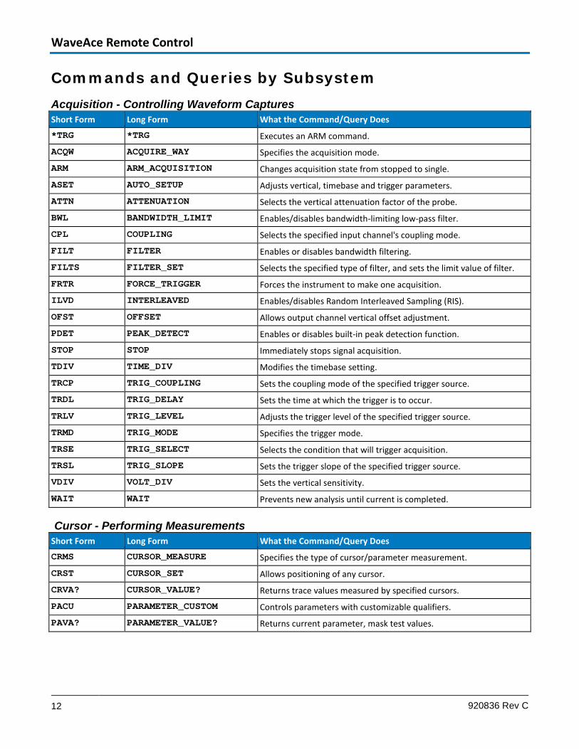
Commands and Queries by Subsystem Acquisition - Controlling Waveform Captures Short Form Long Form What the Command/Query Does
*TRG *TRG Executes an ARM command.
ACQW ACQUIRE_WAY Specifies the acquisition mode.
ARM ARM_ACQUISITION Changes acquisition state from stopped to single.
ASET AUTO_SETUP Adjusts vertical, timebase and trigger parameters.
ATTN ATTENUATION Selects the vertical attenuation factor of the probe.
BWL BANDWIDTH_LIMIT Enables/disables bandwidth-limiting low-pass filter.
CPL COUPLING Selects the specified input channel's coupling mode.
FILT FILTER Enables or disables bandwidth filtering.
FILTS FILTER_SET Selects the specified type of filter, and sets the limit value of filter. FRTR FORCE_TRIGGER Forces the instrument to make one acquisition.
ILVD INTERLEAVED Enables/disables Random Interleaved Sampling (RIS).
OFST OFFSET Allows output channel vertical offset adjustment.
PDET PEAK_DETECT Enables or disables built-in peak detection function.
STOP STOP Immediately stops signal acquisition.
TDIV TIME_DIV Modifies the timebase setting.
TRCP TRIG_COUPLING Sets the coupling mode of the specified trigger source.
TRDL TRIG_DELAY Sets the time at which the trigger is to occur.
TRLV TRIG_LEVEL Adjusts the trigger level of the specified trigger source.
TRMD TRIG_MODE Specifies the trigger mode.
TRSE TRIG_SELECT Selects the condition that will trigger acquisition.
TRSL TRIG_SLOPE Sets the trigger slope of the specified trigger source.
VDIV VOLT_DIV Sets the vertical sensitivity.
WAIT WAIT Prevents new analysis until current is completed.
Cursor - Performing Measurements Short Form Long Form What the Command/Query Does
CRMS CURSOR_MEASURE Specifies the type of cursor/parameter measurement.
CRST CURSOR_SET Allows positioning of any cursor.
CRVA? CURSOR_VALUE? Returns trace values measured by specified cursors.
PACU PARAMETER_CUSTOM Controls parameters with customizable qualifiers.
PAVA? PARAMETER_VALUE? Returns current parameter, mask test values.
Operator's Manual
13
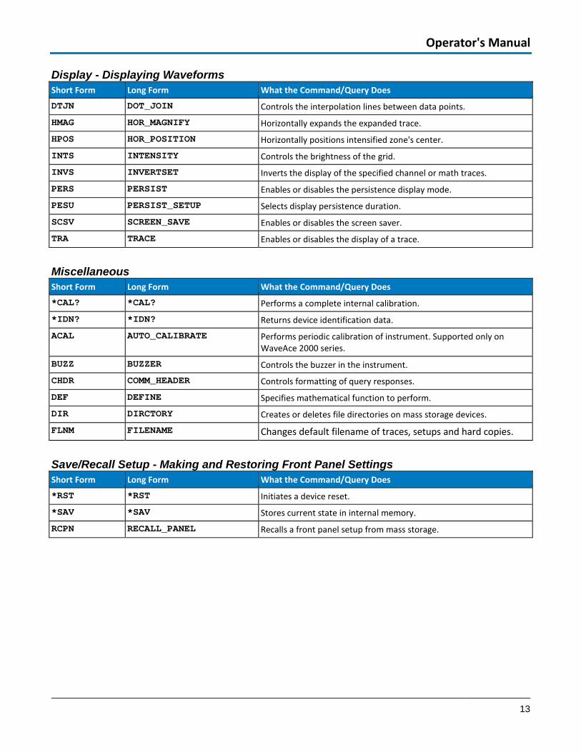
Display - Displaying Waveforms Short Form Long Form What the Command/Query Does
DTJN DOT_JOIN Controls the interpolation lines between data points.
HMAG HOR_MAGNIFY Horizontally expands the expanded trace.
HPOS HOR_POSITION Horizontally positions intensified zone's center.
INTS INTENSITY Controls the brightness of the grid.
INVS INVERTSET Inverts the display of the specified channel or math traces.
PERS PERSIST Enables or disables the persistence display mode.
PESU PERSIST_SETUP Selects display persistence duration.
SCSV SCREEN_SAVE Enables or disables the screen saver.
TRA TRACE Enables or disables the display of a trace.
Miscellaneous Short Form Long Form What the Command/Query Does
*CAL? *CAL? Performs a complete internal calibration.
*IDN? *IDN? Returns device identification data.
ACAL AUTO_CALIBRATE Performs periodic calibration of instrument. Supported only on WaveAce 2000 series.
BUZZ BUZZER Controls the buzzer in the instrument.
CHDR COMM_HEADER Controls formatting of query responses.
DEF DEFINE Specifies mathematical function to perform.
DIR DIRCTORY Creates or deletes file directories on mass storage devices.
FLNM FILENAME Changes default filename of traces, setups and hard copies.
Save/Recall Setup - Making and Restoring Front Panel Settings Short Form Long Form What the Command/Query Does
*RST *RST Initiates a device reset.
*SAV *SAV Stores current state in internal memory.
RCPN RECALL_PANEL Recalls a front panel setup from mass storage.
WaveAce Remote Control
14 920836 Rev C
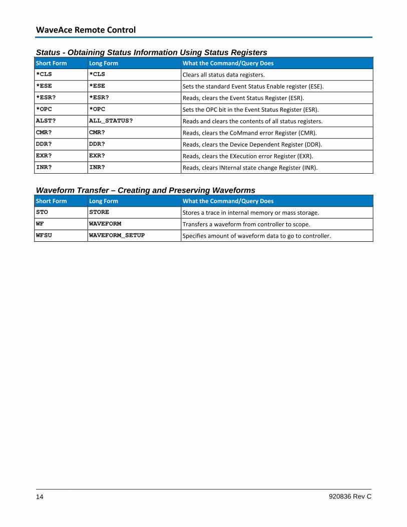
Status - Obtaining Status Information Using Status Registers Short Form Long Form What the Command/Query Does
*CLS *CLS Clears all status data registers.
*ESE *ESE Sets the standard Event Status Enable register (ESE).
*ESR? *ESR? Reads, clears the Event Status Register (ESR).
*OPC *OPC Sets the OPC bit in the Event Status Register (ESR).
ALST? ALL_STATUS? Reads and clears the contents of all status registers.
CMR? CMR? Reads, clears the CoMmand error Register (CMR).
DDR? DDR? Reads, clears the Device Dependent Register (DDR).
EXR? EXR? Reads, clears the EXecution error Register (EXR).
INR? INR? Reads, clears INternal state change Register (INR).
Waveform Transfer – Creating and Preserving Waveforms Short Form Long Form What the Command/Query Does
STO STORE Stores a trace in internal memory or mass storage.
WF WAVEFORM Transfers a waveform from controller to scope.
WFSU WAVEFORM_SETUP Specifies amount of waveform data to go to controller.

Operator's Manual
15
Commands and Queries by Name (Alphabetical) Short Form Long Form What the Command/Query Does
*CAL? *CAL? Performs a complete internal calibration.
*CLS *CLS Clears all status registers.
*ESE *ESE Sets the standard Event Status Enable register (ESE).
*ESR? *ESR? Reads, clears the Event Status Register (ESR).
*IDN? *IDN? Returns device identification data.
*OPC *OPC Sets the OPC bit in the Event Status Register (ESR).
*RST *RST Initiates a device reset.
*SAV *SAV Stores current state in internal memory.
*TRG *TRG Executes an ARM command.
ACAL AUTO_CALIBRATE Performs periodic calibration of instrument. Supported only on WaveAce 2000 series.
ACQW ACQUIRE_WAY Specifies the acquisition mode.
ALST? ALL_STATUS? Reads and clears the contents of all status registers.
ARM ARM_ACQUISITION Changes acquisition state from stopped to single.
ASET AUTO_SETUP Adjusts vertical, timebase and trigger parameters.
ATTN ATTENUATION Selects the vertical attenuation factor of the probe.
BUZZ BUZZER Controls the buzzer in the instrument.
BWL BANDWIDTH_LIMIT Enables/disables bandwidth-limiting low-pass filter.
CHDR COMM_HEADER Controls formatting of query responses.
CMR? CMR? Reads, clears the CoMmand error Register (CMR).
CPL COUPLING Selects the specified input channel's coupling mode.
CRMS CURSOR_MEASURE Specifies the type of cursor/parameter measurement.
CRST CURSOR_SET Allows positioning of any cursor.
CRVA? CURSOR_VALUE? Returns trace values measured by specified cursors.
DDR? DDR? Reads, clears the Device Dependent Register (DDR).
DEF DEFINE Specifies mathematical function to perform.
DIR DIRCTORY Creates or deletes file directories on mass storage devices.
DTJN DOT_JOIN Controls the interpolation lines between data points.
EXR? EXR? Reads, clears the EXecution error Register (EXR).
FILT FILTER Enables or disables bandwidth filtering.
FILTS FILTER_SET Selects the specified type of filter, and sets the limit value of filter. FLNM FILENAME Changes default filename of traces, setups and hard copies. FRTR FORCE_TRIGGER Forces the instrument to make one acquisition.
HMAG HOR_MAGNIFY Horizontally expands the expanded trace.
HPOS HOR_POSITION Horizontally positions intensified zone's center.

WaveAce Remote Control
16 920836 Rev C
Short Form Long Form What the Command/Query Does
ILVD INTERLEAVED Enables/disables Random Interleaved Sampling (RIS).
INR? INR? Reads, clears INternal state change Register (INR).
INTS INTENSITY Controls the brightness of the grid.
INVS INVERTSET Inverts the display of the specified channel or math traces.
OFST OFFSET Allows output channel vertical offset adjustment.
PACU PARAMETER_CUSTOM Controls parameters with customizable qualifiers.
PAVA? PARAMETER_VALUE? Returns current parameter, mask test values.
PDET PEAK_DETECTED Enables or disables built-in peak detection function.
PERS PERSIST Enables or disables the persistence display mode.
PESU PERSIST_SETUP Selects display persistence duration.
RCPN RECALL_PANEL Recalls a front panel setup from mass storage.
SCSV SCREEN_SAVE Enables or disables the screen saver.
STO STORE Stores a trace in internal memory or mass storage.
STOP STOP Immediately stops signal acquisition.
TDIV TIME_DIV Modifies the timebase setting.
TRA TRACE Enables or disables the display of a trace.
TRCP TRIG_COUPLING Sets the coupling mode of the specified trigger source.
TRDL TRIG_DELAY Sets the time at which the trigger is to occur.
TRLV TRIG_LEVEL Adjusts the trigger level of the specified trigger source.
TRMD TRIG_MODE Specifies the trigger mode.
TRSE TRIG_SELECT Selects the condition that will trigger acquisition.
TRSL TRIG_SLOPE Sets the trigger slope of the specified trigger source.
VDIV VOLT_DIV Sets the vertical sensitivity.
WAIT WAIT Prevents new analysis until current is completed.
WF WAVEFORM Transfers a waveform from controller to scope.
WFSU WAVEFORM_SETUP Specifies amount of waveform data to go to controller.

Operator's Manual
17
Part II: Command Reference All remote control commands and queries recognized by the instrument can be executed in either a local or remote state.
This section lists commands and queries by short name in alphabetical order within subsystem.
Command Notation A brief explanation of the operation performed by the command or query is followed by the formal syntax, with the full-name header given in lowercase characters and the short form derived from it in uppercase characters (e.g., DoT_JoiN and DTJN).
Where applicable, the syntax of the query is given with the format of its response. For each command, a short GPIB example illustrating a typical use is also provided. The device name of the oscilloscope is defined as SCOPE% in the examples, but you can substitute any valid device name.
Queries obtain information. They are recognized by ? following their headers. Many commands can be used as queries simply by adding the question mark.
TIP: You can always find out the correct form of a command by manually setting up the oscilloscope in the exact required condition, and then sending a query which corresponds to the command. The reply from the oscilloscope can then be copied into your program as a command.
Commands make use of the following notational symbols:
• < > - Angular brackets enclose words used as placeholders of which there are two types - the header path and the data parameter of a command.
• := - A colon followed by an equals sign separates a placeholder from the description of the type and range of values for use in a command instead of the placeholder.
• { } - Braces enclose a list of choices, one of which must be made.
• [ ] - Square brackets enclose optional items.
• … - An ellipsis indicates the items to its left and right can be repeated any number of times.
WaveAce Remote Control
18 920836 Rev C
ACQUISITION - *TRG The *TRG command executes an ARM command. *TRG is the equivalent of the 488.1 GET (Group Execute Trigger) message.
Command Syntax
*TRG
Related Commands
ARM_ACQUISITION, STOP, WAIT, FORCE_TRIGGER
ACQUISITION - ARM_ACQUISITION, ARM The ARM_ACQUISITION command arms the scope or forces a single acquisition if it is already armed.
Command Syntax
ARM_acquisition
Related Commands
STOP, *TRG, TRIG_MODE, WAIT, FORCE_TRIGGER
ACQUISITION - AUTO_SETUP, ASET The AUTO_SETUP command displays the input signal(s) by adjusting the vertical, timebase, and trigger parameters. AUTO_SETUP operates on all channels.
If signals are detected on several channels, the lowest numbered channel with a signal determines the selection of the timebase and trigger source.
If only one input channel is turned on, the timebase will be adjusted for that channel.
Command Syntax Auto_SETup

Operator's Manual
19
ACQUISITION – ACQUIRE_WAY, ACQW The ACQUIRE_WAY command specifies the acquisition mode.
The ACQUIRE_WAY? query returns the current acquisition mode.
Command Syntax <channel>: ACQuire_Way <mode>[,<time>]
<channel>:= {C1,C2,C3,C4,EX,EX10}
<mode>:= {SAMPLING, PEAK_DETECT, AVERAGE}
<time>:= {4,16,32,64,128,256}
NOTE: The time parameter can only be set with the AVERAGE acquisition mode.
Query Syntax <channel>:ACQUIRE_WAY?
Response Format <channel>: ACQuire_Way <mode>[,<time>]
Example The following command sets the acquisition mode to Average every 16: C1:ATTN 100
Related Commands AVGA, PDET
WaveAce Remote Control
20 920836 Rev C
ACQUISITION - ATTENUATION, ATTN The ATTENUATION command selects the vertical attenuation factor of the probe. Values up to 1000 can be specified.
The ATTENUATION? query returns the attenuation factor of the specified channel.
Command Syntax <channel>: ATTeNuation <attenuation>
<channel>:= {C1,C2,C3,C4,EX,EX10}
<attenuation>:= {1,5,10,50,100,500,1000}
Query Syntax <channel>:ATTeNuation?
Response Format <channel>:ATTeNuation <attenuation>
Example The following instruction sets to 100 the attenuation factor of Channel 1: C1:ATTN 100
Operator's Manual
21
ACQUISITION - BANDWIDTH_LIMIT, BWL The BWL command enables or disables the bandwidth limit (low-pass filter) of the specified input channel.
The BWL? query returns the enabled/disabled status. If all the channels are in the same state, it returns the state; if not, it returns each individual channel state.
Command Syntax BandWidth_Limit <channel>,<mode>[,<channel>,<mode>...]
<channel>:= {C1, C2, C3, C4}
<mode>: = {ON, OFF}
NOTE: Unlike other commands, do not use the Header path to specify the trace, enter it as one of the parameters of the command, as shown in the example below.
Query Syntax BWL?
Response Format BWL <mode>
Example This instruction sets a low-pass filter on Channel 2: BWL C2,ON
WaveAce Remote Control
22 920836 Rev C
ACQUISITION - COUPLING, CPL The COUPLING command selects the coupling mode of the specified input channel.
The COUPLING? query returns the coupling mode of the specified channel.
Command Syntax <channel>:CouPLing <coupling>
<channel>:= {C1,C2,C3,C4,M1,M2,M3,M4,M5,M6,M7,M8,M9,M10}
<coupling>:= {A1M*, D1M*, GND}
* Attenuation pertains only to instruments with a probe connected.
Query Syntax <channel>:CouPLing?
Response Format <channel>:CouPLing <coupling>
<coupling>:= {A1M, D1M, D50, GND, OVL}
COUPLING OVL is returned in the event of signal overload while in DC 50 Ω coupling. In this condition, the oscilloscope will disconnect the input.
Example The following instruction sets the coupling of Channel 2 to Ground: C2:CPL GND
Operator's Manual
23
ACQUISITION - FILTER, FILT The FILTer command enables or disables hi/lowpass filter of the specified trace.
The response to the FILTer? query indicates whether the filter of specified trace is enabled.
Command Syntax <channel>:FILTER <state>
<channel> := {C1,C2,C3,C4}
<state> := {ON,OFF}
Query Syntax <channel>:FILTER?
Response Format <channel>:FILTER <state>
Example The following command enables the filter of channel 1: C1:FILT ON
Related Commands FILTS

WaveAce Remote Control
24 920836 Rev C
ACQUISITION – FILT_SET, FILTS The FILT_Set command selects the specified type of hi/lowpass filter, and sets the limit values of filter.
The response to the FILT_Set? query indicates current parameter of the filter.
Command Syntax <channel>:FILT_SET TYPE <type>,<limit>,<limit_value>[,<limit>,<limit_value>]
<channel> := {C1,C2,C3,C4}
<type> := {LP,HP,BP,BR}
<limit> := {UPPLIMIT,LOWLIMIT}
LP is lowpass, HP is highpass, BP is bandpass, BR is bandreject
The <type> must be related to any <limit> set.
Query Syntax <channel>:FILT_SET?
Response Format <channel>:FILTER TYPE,<type>,<limit>,<limit_value>[,<limit>,<limit_value>]
Example The following command changes the type of filter to bandpass, and sets the upplimit to 200 KHz and the lowlimit to 100 KHz: C1:FILTS TYPE,BP,UPPLIMIT,200KHz,LOWLIMIT,100KHz
Related Commands FILT

Operator's Manual
25
ACQUISITION - FORCE_TRIGGER, FRTR Causes the instrument to make one acquisition.
Command Syntax FoRce_TRigger
Example Either of the following instructions forces the oscilloscope to make one acquisition: TRMD SINGLE;ARM;FRTR...
TRMD STOP;ARM;FRTR...
ACQUISITION - INTERLEAVED, ILVD The INTERLEAVED command enables or disables Equivalent Time Mode for timebase settings where both single shot and RIS mode are available.
Equivalent Time Mode is not available for sequence mode acquisitions. If sequence mode is on, ILVD ON turns it off.
The response to the INTERLEAVED? query indicates whether the oscilloscope is in Equivalent Time Mode.
Command Syntax InterLeaVeD <mode>
<mode>:= {ON, OFF}
Query Syntax InterLeaVeD?
Response Format InterLeaVeD <mode>
Example The following instructs the oscilloscope to use Equivalent Time Mode: ILVD ON
Related Commands
TIME_DIV, TRIG_MODE
WaveAce Remote Control
26 920836 Rev C
ACQUISITION - OFFSET, OFST The OFFSET command allows adjustment of the vertical offset of the specified input channel. The OFFSET? query returns the DC offset value of the specified channel.
The maximum ranges depend on the fixed sensitivity setting. If an out-of-range value is entered, the oscilloscope is set to the closest possible value.
NOTE: The probe attenuation factor is not taken into account in offset adjustments. Also, the unit V is optional.
Command Syntax <channel>:OFfSeT <offset>
<channel>:= {C1, C2, C3, C4}
<offset>:= Refer to datasheet specification for your Teledyne LeCroy oscilloscope at teledynelecroy.com.
Query Syntax <channel>:OFfSeT?
Response Format <channel>:OFfSeT <offset>
Example The following instruction sets the offset of Channel 2 to -3 V:
C2:OFST -3V

Operator's Manual
27
ACQUISITION – PEAK_DETECT, PDET The PEAK_DETECT command switches ON or OFF the peak detector built into the acquisition system.
The PEAK_DETECT? query returns the current status of the peak detector.
Command Syntax Peak_DETect <state>
<state> : = {ON, OFF}
Query Syntax Peak_DETect?
Response Format PDET <state>
Example The following instruction turns on the peak detector: PDET ON
ACQUISITION - STOP The STOP command immediately stops the acquisition of a signal. If the trigger mode is AUTO or NORM, STOP places the oscilloscope in STOPPED trigger mode to prevent further acquisition.
Command Syntax STOP
Related Commands
ARM_ACQUISITION, TRIG_MODE, WAIT, FORCE_TRIGGER

WaveAce Remote Control
28 920836 Rev C
ACQUISITION - TIME_DIV, TDIV The TIME_DIV command modifies the timebase setting. The new timebase setting can be specified with units: N/NS for nanoseconds, U/US for microseconds, M/MS for milliseconds, or S for seconds. Alternatively, you can use exponential notation: 10E-6.
The TIME_DIV? query returns the current timebase setting.
Command Syntax
Time_DIV <value>
<value>:= Refer to datasheet specification for your Teledyne LeCroy oscilloscope at at teledynelecroy.com.
The default unit S (seconds) is optional.
Query Syntax
Time_DIV?
Response Format
Time_DIV <value>
Example The following instruction sets the time base to 500 µs/div:
TDIV 500US
The following instruction sets the time base to 2 msec/div:
TDIV 0.002
Related Commands
TRIG_DELAY, TRIG_MODE
Operator's Manual
29
ACQUISITION - TRIG_COUPLING, TRCP The TRIG_COUPLING command sets the coupling mode of the specified trigger source.
The TRIG_COUPLING? query returns the trigger coupling of the selected source.
Command Syntax <trig_source>:TRig_CouPling <coupling>
<trig_source>:= {C1,C2,C3,C4}
<coupling>:= {AC,DC,HFREI,LFREI}
Query Syntax
<trig_source>:TRig_CouPling?
Response Format
<trig_source>:TRig_CouPling <trig_coupling>
Example The following instruction sets the coupling mode of the trigger source Channel 2 to DC:
C2:TRCP DC
Related Commands
TRIG_COUPLING, TRIG_DELAY, TRIG_LEVEL, TRIG_MODE, TRIG_SELECT, TRIG_SLOPE

WaveAce Remote Control
30 920836 Rev C
ACQUISITION - TRIG_DELAY, TRDL The TRIG_DELAY command sets the time at which the trigger is to occur with respect to the nominal zero delay position, which defaults to the center of the grid.
RANGE Negative delay: 0 to - divisions x Time/div supported by scope
Postive delay: 0 to + division x Time/div supported by scope
If a value outside these ranges is specified, the trigger time is set to the nearest limit.
Command Syntax TRig_DeLay <value>
<value>:= delay time as per RANGE previously described in this topic.
NOTE: The value parameter is optional.
Query Syntax TRig_DeLay?
Response Format The response to the TRIG_DELAY? query indicates the trigger time with respect to the first acquired data point. TRig_DeLay <value>
Example The following instruction sets the trigger delay to -20 S (post-trigger): TRDL -20S
Related Commands
TIME_DIV, TRIG_COUPLING, TRIG_LEVEL, TRIG_MODE, TRIG_SELECT, TRIG_SLOPE
Operator's Manual
31
ACQUISITION - TRIG_LEVEL, TRLV The TRIG_LEVEL command adjusts the trigger level of the specified trigger source. An out-of-range value will be adjusted to the closest legal value.
The TRIG_LEVEL? query returns the current trigger level.
Command Syntax [<trig_source>]:TRig_LeVel <trig_level>
<trig_source>:= {C1,C2,C3,C4,EX5}
Query Syntax
<trig_source>:TRig_LeVel?
Response Format
<trig_source>:TRig_LeVel <trig_level>
Example The following instruction adjusts the trigger level of Channel 2 to -3.4 V:
C2:TRLV -3.4V
Related Commands
TRIG_COUPLING, TRIG_DELAY, TRIG_MODE, TRIG_SELECT, TRIG_SLOPE

WaveAce Remote Control
32 920836 Rev C
ACQUISITION - TRIG_MODE, TRMD The TRIG_MODE command specifies the trigger mode.
The TRIG_MODE? query returns the current trigger mode.
Command Syntax
TRig_MoDe <mode>
<mode>:= {AUTO, NORM, SINGLE, STOP}
Query Syntax
TRig_MoDe?
Response Format
TRig_MoDe <mode>
Example The following instruction selects the normal mode:
TRMD NORM
Related Commands
ARM_ACQUISITION, FORCE_TRIGGER, STOP, TRIG_SELECT, TRIG_COUPLING, TRIG_LEVEL, TRIG_SLOPE

Operator's Manual
33
ACQUISITION - TRIG_SELECT, TRSE The TRIG_SELECT command selects the condition that triggers the acquisition of waveforms. Only the Edge trigger is supported.
Command Syntax TRig_Select EDGE,SR,<source>,HT,TI,HV,<hold_value>
<source>:= {C1,C2,C3,C4,LINE,EX,EX5}
<hold_value>:= Refer to the trigger information provided for your oscilloscope model.
NOTE: When specifying <hold_value>, the unit S (seconds) is optional.
Query Syntax TRig_SElect?
Response Format TRig_SElect <trig_type>,SR,<source>,HT,<hold_type>,HV,<hold_value>
HV2 only returned if <hold_type> is P2 or I2.
Example The following instruction selects the single-source trigger with Channel 1 as trigger source. Hold type and hold value are chosen as "pulse smaller" than 20 ns: TRSE SNG,SR,C1,HT,PS,HV,20 NS

WaveAce Remote Control
34 920836 Rev C
ACQUISITION - TRIG_SLOPE, TRSL The TRIG_SLOPE command sets the trigger slope of the specified trigger source. The TRIG_SLOPE? query returns the trigger slope of the selected source.
Command Syntax <trig_source>:TRig_SLope <trig_slope>
<trig_source>:= {C1,C2,C3,C4,LINE,EX,EX5}
<trig_slope>:= {NEG, POS}
Query Syntax <trig_source>:TRig_SLope?
Response Format <trig_source>:TRig_SLope <trig_slope>
Example The following instruction sets the trigger slope of Channel 2 to negative: C2:TRSL NEG
Related Commands
TRIG_COUPLING, TRIG_DELAY, TRIG_LEVEL, TRIG_MODE, TRIG_SELECT, TRIG_SLOPE
Operator's Manual
35
ACQUISITION - VOLT_DIV, VDIV The VOLT_DIV command sets the vertical sensitivity in Volts/div.
The probe attenuation factor is not taken into account for adjusting vertical sensitivity.
The VOLT_DIV? query returns the vertical sensitivity of the specified channel.
Command Syntax <channel>:Volt_DIV <v_gain>
<channel>:= {C1, C2, C3, C4}
<v_gain>:= Refer to product datasheet at teledynelecroy.com.
NOTE: When specifying <v_gain>, the unit V is optional.
Query Syntax <channel>:Volt_DIV?
Response Format <channel>:Volt_DIV <v_gain>
Example The following instruction sets the vertical sensitivity of channel 1 to 50 mV/div:
C1:VDIV 50MV

WaveAce Remote Control
36 920836 Rev C
ACQUISITION - WAIT The WAIT command prevents your instrument from analyzing new commands until the current acquisition has been completed. The optional argument specifies the timeout (in seconds) after which the scope stops waiting for new acquisitions. If <t> is not given, or if <t> = 0.0, the scope waits indefinitely.
Command Syntax WAIT [<t>]
<t>:= timeout in seconds (default is indefinite)
Example ARM;WAIT;*OPC;C1:PAVA? MAX
This example finds the maximum amplitudes of several signals acquired one after another. ARM starts a new data acquisition. The WAIT command ensures that the maximum is evaluated for the newly acquired waveform.
C1:PAVA? MAX instructs the oscilloscope to evaluate the maximum data value in the Channel 1 waveform.
Related Commands
*TRG, TRIG_MODE, ARM

Operator's Manual
37
CURSOR - CURSOR_MEASURE, CRMS The CURSOR_MEASURE command specifies the type of cursor or parameter measurement to be displayed, and is the main command for displaying parameters and Pass/Fail. Use it to turn on/off cursors.
The CURSOR_MEASURE? query indicates which cursors or parameter measurements are currently displayed.
Command Syntax CuRsor_MeaSure <mode>
<mode>:= {HREL, VREL}
Where: HREL - Horizontal relative cursors. VREL - Vertical relative cursors.
Query Syntax CuRsor_MeaSure?
Response Format CuRsor_MeaSure <mode>
Example The following instruction switches on the vertical relative cursors: CRMS VREL
Related Commands
CURSOR_SET, PARAMETER_VALUE,

WaveAce Remote Control
38 920836 Rev C
CURSOR - CURSOR_SET, CRST The CURSOR_SET command allows you to position any one of the independent cursors at a given grid location. When you are setting a cursor position, you must specify an active trace relative to which the cursor is positioned.
The CURSOR_SET? query retrieves the current position of the cursor(s). The values returned depend on the grid type selected:
HREF Horizontal Cursor A VREF Vertical Cursor A.
HDIF Horizontal Cursor B VDIF Vertical Cursor B.
Command Syntax <trace>:CuRsor_SeT <cursor>,<position>,...
<trace>:= {TA,TB,TC,TD,C1,C2,C3,C4,M1,M2,M3,M4,M5,M6,M7,M8,M9,M10}
<cursor>:= {HABS, VABS, HREF, HDIF, VREF, VDIF}
<position>:= 0 to 10 DIV (horizontal);-3.99 to 3.99 DIV (vertical)
Query Syntax <trace>:CuRsor_SeT? <cursor>
<cursor>:= {HREF, HDIF, VREF, VDIF}
No <cursor> implies ALL, even though not all are visible.
Response Format <trace>:CuRsor_SeT <cursor>,<position>,...<cursor>,<position>
If the position of a cursor cannot be determined, its position will be given as UNDEF.
Example The following instruction positions the VREF and VDIF cursors at +3 DIV and -2 DIV respectively, using Trace TA as a reference: TA:CRST VREF,3DIV,VDIF,-2DIV
Related Commands
CURSOR_MEASURE, CURSOR_VALUE?, PARAMETER_VALUE?
Operator's Manual
39
CURSOR - CURSOR_VALUE?, CRVA? The CURSOR_VALUE? query returns the values measured by the specified cursors. The PARAMETER_VALUE? query is used to obtain measured waveform parameter values.
The keyword ALL should not be used; neither should multiple keywords. If they are used, the word UNDEF is returned.
For the CRVA? query to work, the specified trace must be visible, and the current cursor mode must be the same as in the query. If it is not the same, UNDEF is returned.
Query Syntax <trace>:CuRsor_VAlue? [<mode>]
<trace>:= {TA,TB,TC,TD,C1,C2,C3,C4}
<mode>:= {HABS, HREL, VABS, VREL}
Where: HABS - Horizontal absolute HREL - Horizontal relative VABS – Vertical absolute VREL – Vertical relative
Response Format <trace>:CuRsor_VAlue HABS,<abs_hori>,<abs_vert>
<trace>:CuRsor_VAlue HREL,<delta_hori>,<delta_vert>,<abs vert_ref>, <abs vert_dif>,<slope>
The dV/dt value <slope> is displayed in the appropriate trace label box. <trace>:CuRsor_VAlue VABS,<abs_vert>
<trace>:CuRsor_VAlue VREL,<delta_vert>
For horizontal cursors, both horizontal and vertical values are given. For vertical cursors only vertical values are given.
Example The following query reads the measured absolute horizontal value of the HABS cursor on Channel 2: C2:CRVA? HABS
Response message: C2:CRVA HABS,34.2E-6 S, 244 E-3 V

WaveAce Remote Control
40 920836 Rev C
CURSOR - PARAMETER_CUSTOM, PACU The PArameter_CUstom command controls the placement of custom cursors and can also be used to assign any parameter for histogramming.
The command allows you to specify on which line (1 to 5) of the parameter table the cursor value will appear when viewed on the WaveAce display.
NOTE: Use PAVA? to read the value of parameters that were set up with PACU.
Command Syntax
Parameter_Custom <line>,<parameter>,<source>
Where: <line>:= 1 to 5
<parameter>:= parameter from the table below or returned with the PAVA? query
<source>:= {C1,C2,C3,C4,C1-C2,C1-C3,C1-C4,C2-C3,C2-C4,C3-C4,TA,TB,TC,TD}
NOTE: Multi-source expressions (e.g., C1-C2) used only with delay measurements PHASE, FRR, FRF, FFR, FFF, LRR, LRF, LFR, and LFF.
Parameters Parameter Definition
AMPL V Amplitude
BASE V Base
CRMS Root mean squared (current)
CMEAN V Average
DUTY + Duty cycle
FALL Fall time 90% to 10%
FFF Time between first falling edge of Source 1 and falling edge of Source 2
FFR Time between first falling edge of Source 1 and rising edge of Source 2
FPRE Falling edge preshoot
FREQ Frequency
FRF Time between first rising edge of Source 1 and falling edge of Source 2
FRR Time between first rising edge of Source 1 and rising edge of Source 2
LFF Time between last falling edge of Source 1 and falling edge of Source 2
LFR Time between last falling edge of Source 1 and rising edge of Source 2
LRF Time between last rising edge of Source 1 and falling edge of Source 2
LRR Time between last rising edge of Source 1 and rising edge of Source 2
Operator's Manual
41
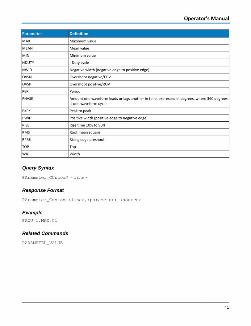
Parameter Definition
MAX Maximum value
MEAN Mean value
MIN Minimum value
NDUTY - Duty cycle
NWID Negative width (negative edge to positive edge)
OVSN Overshoot negative/FOV
OVSP Overshoot positive/ROV
PER Period
PHASE Amount one waveform leads or lags another in time, expressed in degrees, where 360 degrees is one waveform cycle
PKPK Peak to peak
PWID Positive width (positive edge to negative edge)
RISE Rise time 10% to 90%
RMS Root mean square
RPRE Rising edge preshoot
TOP Top
WID Width
Query Syntax
PArameter_CUstom? <line>
Response Format
PArameter_Custom <line>,<parameter>,<source>
Example PACU 1,MAX,C1
Related Commands
PARAMETER_VALUE
WaveAce Remote Control
42 920836 Rev C
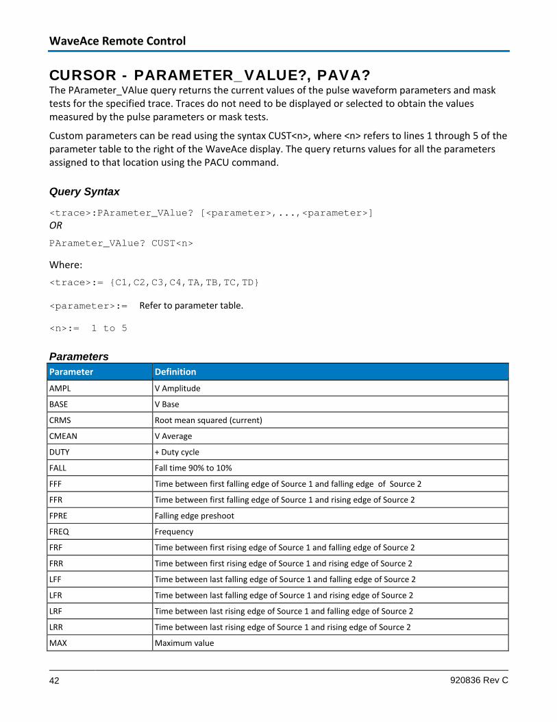
CURSOR - PARAMETER_VALUE?, PAVA? The PArameter_VAlue query returns the current values of the pulse waveform parameters and mask tests for the specified trace. Traces do not need to be displayed or selected to obtain the values measured by the pulse parameters or mask tests.
Custom parameters can be read using the syntax CUST<n>, where <n> refers to lines 1 through 5 of the parameter table to the right of the WaveAce display. The query returns values for all the parameters assigned to that location using the PACU command.
Query Syntax
<trace>:PArameter_VAlue? [<parameter>,...,<parameter>] OR PArameter_VAlue? CUST<n>
Where: <trace>:= {C1,C2,C3,C4,TA,TB,TC,TD}
<parameter>:= Refer to parameter table.
<n>:= 1 to 5
Parameters Parameter Definition
AMPL V Amplitude
BASE V Base
CRMS Root mean squared (current)
CMEAN V Average
DUTY + Duty cycle
FALL Fall time 90% to 10%
FFF Time between first falling edge of Source 1 and falling edge of Source 2
FFR Time between first falling edge of Source 1 and rising edge of Source 2
FPRE Falling edge preshoot
FREQ Frequency
FRF Time between first rising edge of Source 1 and falling edge of Source 2
FRR Time between first rising edge of Source 1 and rising edge of Source 2
LFF Time between last falling edge of Source 1 and falling edge of Source 2
LFR Time between last falling edge of Source 1 and rising edge of Source 2
LRF Time between last rising edge of Source 1 and falling edge of Source 2
LRR Time between last rising edge of Source 1 and rising edge of Source 2
MAX Maximum value

Operator's Manual
43
Parameter Definition
MEAN Mean value
MIN Minimum value
NDUTY - Duty cycle
NWID Negative width (negative edge to positive edge)
OVSN Overshoot negative/FOV
OVSP Overshoot positive/ROV
PER Period
PKPK Peak to peak
PWID Positive width (positive edge to negative edge)
RISE Rise time 10% to 90%
RMS Root mean square
RPRE Rising edge preshoot
TOP Top
WID Width
Response Format
<trace>:PArameter_VAlue <parameter>,<value>,<state>... <value>:= A decimal numeric value <state>:= {OK, AV, PT, IV, NP, GT, LT, OF, UF, OU}
NOTE: If <parameter> is not specified, or is equal to ALL, all standard voltage and time parameters are returned followed by their values and states. When PAVA? Is used to query a Custom parameter, the <trace> prefix is returned for consistency. The source for the measurement is configured using the PACU command.
Example The following instruction query reads the rise time of Trace B (TB):
TB:PAVA? RISE
Response message: TB:PAVA RISE,3.6E-9S,OK
Related Commands
CURSOR_MEASURE, CURSOR_SET, PARAMETER_CUSTOM
WaveAce Remote Control
44 920836 Rev C
DISPLAY - DOT_JOIN, DTJN The DOT_JOIN command controls the interpolation lines between data points. Setting DOT_JOIN ON selects Points in the Display dialog; DOT_JOIN OFF selects Line.
Command Syntax
DOT_JOIN <state>
<state>:= {ON, OFF}
Query Syntax
DoT_JoiN?
Response Format
DoT_JoiN <state>
Example The following instruction turns off the interpolation lines:
DTJN OFF

Operator's Manual
45
DISPLAY - HOR_MAGNIFY, HMAG The HOR_MAGNIFY command horizontally expands traces (zooms) by a specified factor. Magnification factors not within the range of permissible values will be rounded off to the nearest legal value.
The HOR_MAGNIFY? query returns the current magnification factor.
Command Syntax
Hor_MAGnify <factor>
<factor>:= 1 to 2000
Query Syntax
Hor_MAGnify?
Response Format
Hor_MAGnify <factor>
Example The following instruction horizontally magnifies traces by a factor of 5:
HMAG 5
WaveAce Remote Control
46 920836 Rev C
DISPLAY - HOR_POSITION, HPOS The HOR_POSITION command repositions the geometric center of a zoom to display different portions of the trace. Allowed positions range from division 0 through 10. If the source trace was acquired in sequence mode, the shift will only apply to a single segment at a time.
The difference between the specified and the current horizontal position is applied to all zooms. However, if the difference would cause any zoom trace to go outside the left or right screen boundaries, the difference is adapted before being applied to the traces.
The HOR_POSITION? query returns the position of the geometric center of the zoom.
NOTE: Segment number 0 has the special meaning Show All Segments Unexpanded.
Command Syntax
Hor_POSition <hor_position>,<segment>
<hor_position>:= 0 to 10 DIV
<segment>:= 0 to max segments
NOTE: The segment number is only relevant for waveforms acquired in sequence mode; it is ignored in single waveform acquisitions. When the segment number is set to 0, all segments are shown. The unit DIV is optional.
Query Syntax
Hor_POSition?
Response Format
Hor_POSition <hor_position>[,<segment>]
Example The following instruction positions the center of the zoom at division 3:
HPOS 3

Operator's Manual
47
DISPLAY - INTENSITY, INTS The INTenSity command sets the intensity level of the grid and trace.
Command Syntax INTenSity GRID,<value>[PCT],TRACE,<value>[PCT]
Query Syntax INTenSity?
Response Format INTenSity TRACE,<value>,GRID,<value>
Example The following example sets the grid intensity to 60% and trace intensity to 90%. INTS GRID,60,TRACE,90
DISPLAY - INVERTSET, INVS The INVertSet command inverts the display of the specified channel or math traces.
The response to the INVertSet? query indicates whether the specified waveform is invert.
Command Syntax <trace>:INVERTSET <state>
<trace> := {C1,C2,C3,C4,MATH}
<state> := {ON,OFF}
Query Syntax INVertSet?
Response Format <trace>:INVERTSET <state>
Example The following instruction inverts the trace of channel 1: C1:INVS ON
WaveAce Remote Control
48 920836 Rev C
DISPLAY - PERSIST, PERS The PERSIST command enables or disables the persistence display mode.
Command Syntax PERSist <mode>
<mode>:= {ON, OFF}
Query Syntax PERSist?
Response Format PERSist <mode>
Example The following instruction turns the persistence display ON: PERS ON
Related Commands PERSIST_SETUP

Operator's Manual
49
DISPLAY - PERSIST_SETUP, PESU The PERSIST_SETUP command sets the duration of the display, in seconds, when in persistence mode. The persistence can be set on all traces or per trace.
The PERSIST_SETUP? query indicates the current status of the persistence.
Command Syntax PErsist_SetUp <time>
<time>:= {1, 2, 5, infinite}
NOTE: The <mode> argument Top2 used by some older instruments is not supported.
Query Syntax PErsist_SetUp?
Response Format PErsist_SetUp <time>
Example The following instruction sets the variable persistence to 10 seconds on all traces:
PESU 20
Related Commands
PERSIST
WaveAce Remote Control
50 920836 Rev C
DISPLAY – SCREEN SAVE, SCSV The SCREEN_SAVE command controls the automatic Screen Saver, which automatically shuts down the internal color monitor after a preset time.
The SCREEN_SAVE? query indicates whether the automatic screen saver feature is on or off.
NOTE: When the screen save is in effect, the oscilloscope is still fully functional.
Command Syntax SCreen_SaVe <enabled>
<enabled>:= {YES,NO}
Query Syntax SCreen_SaVe?
Response Format SCreen_SaVe <state>
<state>:= {ON,OFF}
Example The following enables the automatic screen saver: SCSV YES
Operator's Manual
51
DISPLAY - TRACE, TRA The TRACE command enables or disables the display of a trace. An environment error is set if an attempt is made to display more than four waveforms. Refer to the table in STATUS - EXR? (on page 66) for more information.
The TRACE? query indicates whether or not the specified trace is displayed.
Command Syntax
<trace>:TRAce <mode>
<trace>:= {C1,C2,C3,C4,TA,TB,TC,TD}
<mode>:= {ON, OFF}
Query Syntax <trace>:TRAce?
Response Format <trace>:TRAce <mode>
Example The following instruction displays Trace C1:
C1:TRA ON
WaveAce Remote Control
52 920836 Rev C
MISCELLANEOUS - *CAL? The *CAL? query causes the oscilloscope to perform an internal self-calibration and generates a response that indicates whether or not your oscilloscope completed the calibration without error. This internal calibration sequence is the same as that which occurs at power-up. At the end of the calibration, after the response has indicated how the calibration terminated, the oscilloscope returns to the state it was in just prior to the calibration cycle.
Query Syntax *CAL?
Response Format *CAL? <diagnostics>
<diagnostics>:= 0 (calibration successful)
Response message (if no failure): *CAL 0
MISCELLANEOUS - *IDN? The *IDN? query causes the instrument to identify itself. The response comprises manufacturer, oscilloscope model, serial number, and firmware revision level.
Query Syntax *IDN?
Response Format *IDN LECROY,<model>,<serial_number>,<firmware_level>
<model>:= A six- or seven-character model identifier
<serial_number>:= A nine- or 10-digit decimal code
<firmware_level>:= major release, minor release, and update levels formatted xx.y.z
Example response message:
*IDN LECROY,WaveAce1012,LCRY2150C12345,5.01.02.09

Operator's Manual
53
MISCELLANEOUS – AUTO-CALIBRATE, ACAL Available only on WaveAce 2000 models, AUTO_CALIBRATE enables or disables automatic calibration of the oscilloscope. If ACAL is ON at power-up, all input channels are periodically calibrated for the current input amplifier and timebase settings, whether the instrument has been adjusted or not. This is separate from the calibration the instrument performs whenever you adjust a gain or offset.
ACAL OFF disables Auto-calibration. You can issue a *CAL? query at any time to fully calibrate the oscilloscope, but periodic calibrations stop if ACAL is OFF.
The response to the AUTO_CALIBRATE? query indicates whether auto-calibration is enabled or disabled.
Command Syntax Auto_CALibrate <state>
<state>:= {ON, OFF}
Query Syntax Auto_CALibrate?
Response Format Auto_CALibrate <state>
Related Commands *CAL?
MISCELLANEOUS - BUZZER, BUZZ The buzzer command controls the built-in buzzer. By means of the BEEP argument, the buzzer can be activated to sound short beeps at key points in the control program.
Command Syntax BUZZer <state>
<state>:= {ON, OFF}
Example The following instruction turns off the buzzer: BUZZ OFF

WaveAce Remote Control
54 920836 Rev C
MISCELLANEOUS - COMM_HEADER, CHDR The COMM_HEADER command controls the way the oscilloscope formats responses to queries. There are three response formats:
• LONG, responses contain the long form of the header : C1:VOLT_DIV 200E-3 V
• SHORT, responses contain the short form of the header : C1:VDIV 200E-3 V
• OFF, headers and units are omitted: 200E-3
Unless you specify otherwise, the SHORT response format is used by default.
This command does not affect the interpretation of messages sent to the oscilloscope. Headers can be sent in their long or short form regardless of the COMM_HEADER setting.
Command Syntax Comm_HeaDeR <mode>
<mode>:= {SHORT, LONG, OFF}
Query Syntax Comm_HeaDeR?
Response Format Comm_HeaDeR <mode>
Example The following instruction sets the response header format to LONG: CHDR LONG

Operator's Manual
55
MISCELLANEOUS - DEFINE, DEF The DEFINE command specifies a mathematical function to be performed. This command is used to control all math tools in the standard oscilloscope.
Command Syntax DEFine EQN,'[<function>]<expression>'
Query Syntax DEFine?
Response Format DEFine EQN,'[<function>]<expression>'
Equations Where <source> is shown enclosed in parentheses ( ), the function is included in the equation.
Function Expression Description
DIFFERENCE <source1>-<source2> Difference of two waveforms.
FFT (<source>) Fast Fourier Transform of waveform.
PRODUCT <source1>*<source2> Product of two waveforms.
RATIO <source1>/<source2> Ratio of two waveforms.
SUM <source1>+<source2> Sum of two waveforms.
Source Values <sourceN>:= {C1,C2,C3,C4}
Examples Compute the product of Channel 1 and Channel 2: DEF EQN,'C1*C2'
Related Commands
INR?, PARAMETER_CUSTOM, PARAMETER_VALUE?
WaveAce Remote Control
56 920836 Rev C
MISCELLANEOUS - DELETE_FILE, DELF The DELETE_FILE command deletes a file from the currently selected directory.
Command Syntax DELF '<filename>'
Example The following instruction deletes a trace file: DELF 'TESTRUN.TRC'
MISCELLANEOUS - DIRECTORY, DIR The DIRECTORY command is used to create or delete file directories on mass storage devices. It also allows selection of the current working directory and listing of files in the directory.
The query response consists of a double-quoted string containing a DOS-like listing of the directory. If no mass storage device is present, or if it is not formatted, the string is left empty.
Command Syntax DIRectory DISK,UDSK,ACTION,<action>,'<directory>'
<action>:= {CREATE, DELETE, SWITCH}
<directory>:= A legal DOS path or filename ( can include the '\' character to define the root directory)
Query Syntax DIRectory? DISK,UDSK
Response Format DIRectory? DISK,UDSK,'<directory>'
<directory>:= A variable length string detailing the file content of the hard disk

Operator's Manual
57
MISCELLANEOUS – FILENAME, FLNM The FILENAME command is used to change the default filename given to any traces, setups or hard copies (screen prints) when being saved to a mass storage device.
Command Syntax FiLeNaMe TYPE,<type>,FILE,'<filename>'
Where: <type>:= {C1,C2,C3,C4,SETUP,TA,TB,TC,TD,HCOOPY}
<filename>:= alphanumeric string of up to 8 characters forming a legal DOS filename, enclosed by quotes.
Query Syntax FiLeNaMe? TYPE,<type>
<type>: {ALL,C1,C2,C3,C4,SETUP,TA,TB,TC,TD,HCOOPY}
Response Format FILENAME TYPE,<type>,FILE,'<filename>'[TYPE,<type>,FILE,'<filename>'…]
Example The following command names Channel 1 waveform file 'TESTWF.DAV': FLNM TYPE,C1,FILE, 'TESTWF'
NOTE: The file’s extension is automatically specified by the oscilloscope.
Related Commands DIRECTORY, DELETE_FILE

WaveAce Remote Control
58 920836 Rev C
SAVE/RECALL SETUP - *RCL The *RCL command sets the state of your instrument, using one of the six non-volatile panel setups (Panel 1 to Panel 6), by recalling the complete front panel setup of the oscilloscope. Entering panel setup 0 corresponds to the default panel setup.
The *RCL command produces an effect the opposite of the *SAV command.
If the desired panel setup is not acceptable, the EXecution error status Register (EXR) is set and the EXE bit of the standard Event Status Register (ESR) is set.
Command Syntax *RCL <panel_setup>
<panel_setup>:= 0 to 6
Example The following instruction recalls your instrument setup previously stored in panel setup 3: *RCL 3
Related Commands
*SAV, EXR?
SAVE/RECALL SETUP - *RST The *RST command initiates a device reset. *RST sets all eight traces to the GND line and recalls the default setup.
Command Syntax *RST
Related Commands
*CAL?
Operator's Manual
59
SAVE/RECALL SETUP - *SAV The *SAV command stores the current state of your instrument in non-volatile internal memory. The *SAV command stores the complete front panel setup of the oscilloscope at the time the command is issued.
NOTE: Communication parameters (those modified by the commands COMM_HEADER and WAVEFORM_SETUP) are not saved when *SAV is used.
Command Syntax *SAV <panel_setup>
<panel_setup>:= 1 to 6
Example The following instruction saves the current instrument setup in panel setup 3: *SAV 3
Related Commands
PANEL_SETUP
SAVE/RECALL SETUP - RECALL_PANEL, RCPN The RECALL_PANEL command recalls a front panel setup from the root directory on an external storage device (USB drive).
Command Syntax ReCall_PaNel DISK,UDSK,FILE,'<filename>'
<filename>:= A string of up to characters with the extension .SET.
Example The following instruction recalls the front panel setup from file P012.SET on the USB drive: RCPN DISK,UDSK,FILE,'P012.SET'
Related Commands
PANEL_SETUP, *SAV

WaveAce Remote Control
60 920836 Rev C
STATUS - *CLS The *CLS command clears all status data registers.
Command Syntax *CLS
Related Commands
ALL_STATUS, CMR, DDR, *ESR, EXR, *STB
STATUS - *ESE The *ESE command sets the value of the ESB bit in the Event Status Enable register (ESE). The *ESE? query reads the contents of the ESE register.
Command Syntax *ESE <value>
<value>:= 0 to 255
Query Syntax *ESE?
Response Format *ESE <value>
Example The following allows the ESB bit to be set if a user request (URQ bit 6, decimal 64) and/or a device dependent error (DDE bit 3, decimal 8) occurs. Summing these values yields the ESE register mask 64+8=72. *ESE 72
Related Commands
*ESR?
Operator's Manual
61
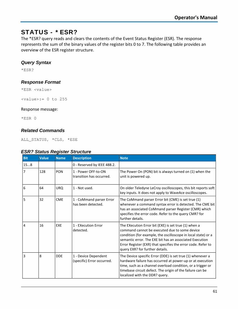
STATUS - *ESR? The *ESR? query reads and clears the contents of the Event Status Register (ESR). The response represents the sum of the binary values of the register bits 0 to 7. The following table provides an overview of the ESR register structure.
Query Syntax *ESR?
Response Format *ESR <value>
<value>:= 0 to 255
Response message:
*ESR 0
Related Commands
ALL_STATUS, *CLS, *ESE
ESR? Status Register Structure Bit Value Name Description Note
15...8 0 - Reserved by IEEE 488.2.
7 128 PON 1 - Power OFF-to-ON transition has occurred.
The Power On (PON) bit is always turned on (1) when the unit is powered up.
6 64 URQ 1 - Not used. On older Teledyne LeCroy oscilloscopes, this bit reports soft key inputs. It does not apply to WaveAce oscilloscopes.
5 32 CME 1 - CoMmand parser Error has been detected.
The CoMmand parser Error bit (CME) is set true (1) whenever a command syntax error is detected. The CME bit has an associated CoMmand parser Register (CMR) which specifies the error code. Refer to the query CMR? for further details.
4 16 EXE 1 - EXecution Error detected.
The EXecution Error bit (EXE) is set true (1) when a command cannot be executed due to some device condition (for example, the oscilloscope in local state) or a semantic error. The EXE bit has an associated Execution Error Register (EXR) that specifies the error code. Refer to query EXR? for further details.
3 8 DDE 1 - Device Dependent (specific) Error occurred.
The Device specific Error (DDE) is set true (1) whenever a hardware failure has occurred at power-up or at execution time, such as a channel overload condition, or a trigger or timebase circuit defect. The origin of the failure can be localized with the DDR? query.

WaveAce Remote Control
62 920836 Rev C
Bit Value Name Description Note
2 4 QYE 1 - QuerY Error occurred. The QuerY Error bit (QYE) is set true (1) whenever (a) an attempt is made to read data from the Output Queue when no output is either present or pending, (b) data in the Output Queue has been lost, (c) both output and input buffers are full (deadlock state), (d) an attempt is made by the controller to read before having sent an <END>, (e) a command is received before the response to the previous query was read (output buffer flushed).
1 2 RQC 0 - Oscilloscope never ReQuests bus Control.
The ReQuest Control bit (RQC) is always false (0), as the oscilloscope has no GPIB controlling capability.
0 1 OPC 0 - OPeration Complete bit not used.
The OPeration Complete bit (OPC) is set true (1) whenever *OPC has been received, since commands and queries are strictly executed in sequential order. The oscilloscope starts processing a command only when the previous command has been entirely executed
STATUS - *OPC The *OPC (OPeration Complete) command sets to true the OPC bit (bit 0) in the Standard Event Status Register (ESR).
The *OPC? query always responds with the ASCII character 1 because the oscilloscope only responds to the query when the previous commands are entirely executed. Since *OPC? executes only when processing is complete, it is recommended for synchronization purposes.
Command Syntax
*OPC
Query Syntax
*OPC?
Response Format
*OPC 1
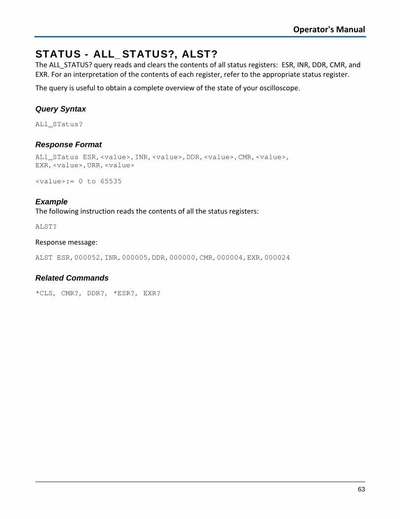
Operator's Manual
63
STATUS - ALL_STATUS?, ALST? The ALL_STATUS? query reads and clears the contents of all status registers: ESR, INR, DDR, CMR, and EXR. For an interpretation of the contents of each register, refer to the appropriate status register.
The query is useful to obtain a complete overview of the state of your oscilloscope.
Query Syntax
ALl_STatus?
Response Format ALl_STatus ESR,<value>,INR,<value>,DDR,<value>,CMR,<value>, EXR,<value>,URR,<value>
<value>:= 0 to 65535
Example The following instruction reads the contents of all the status registers:
ALST?
Response message:
ALST ESR,000052,INR,000005,DDR,000000,CMR,000004,EXR,000024
Related Commands
*CLS, CMR?, DDR?, *ESR?, EXR?

WaveAce Remote Control
64 920836 Rev C
STATUS - CMR? The CMR? query reads and clears the contents of the CoMmand error Register (refer to the following table for details) which specifies the last syntax error type detected by your oscilloscope.
Query Syntax CMR?
Response Format CMR <value>
<value>:= 0 to 13
Related Commands
ALL_STATUS?, *CLS
CMR? Status Register Structure Value Description
1 Unrecognized command/query header.
2 Illegal header path.
3 Illegal number.
4 Illegal number suffix.
5 Unrecognized keyword.
6 String error.
7 GET embedded in another message.
10 Arbitrary data block expected.
11 Non-digit character in byte count field of arbitrary data block.
12 EOI detected during definite length data block transfer.
13 Extra bytes detected during definite length data block transfer.
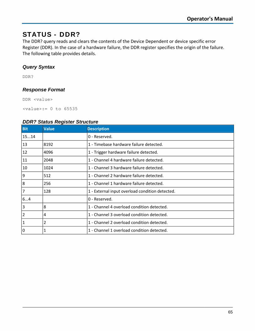
Operator's Manual
65
STATUS - DDR? The DDR? query reads and clears the contents of the Device Dependent or device specific error Register (DDR). In the case of a hardware failure, the DDR register specifies the origin of the failure. The following table provides details.
Query Syntax
DDR?
Response Format
DDR <value>
<value>:= 0 to 65535
DDR? Status Register Structure Bit Value Description
15...14 0 - Reserved.
13 8192 1 - Timebase hardware failure detected.
12 4096 1 - Trigger hardware failure detected.
11 2048 1 - Channel 4 hardware failure detected.
10 1024 1 - Channel 3 hardware failure detected.
9 512 1 - Channel 2 hardware failure detected.
8 256 1 - Channel 1 hardware failure detected.
7 128 1 - External input overload condition detected.
6...4 0 - Reserved.
3 8 1 - Channel 4 overload condition detected.
2 4 1 - Channel 3 overload condition detected.
1 2 1 - Channel 2 overload condition detected.
0 1 1 - Channel 1 overload condition detected.
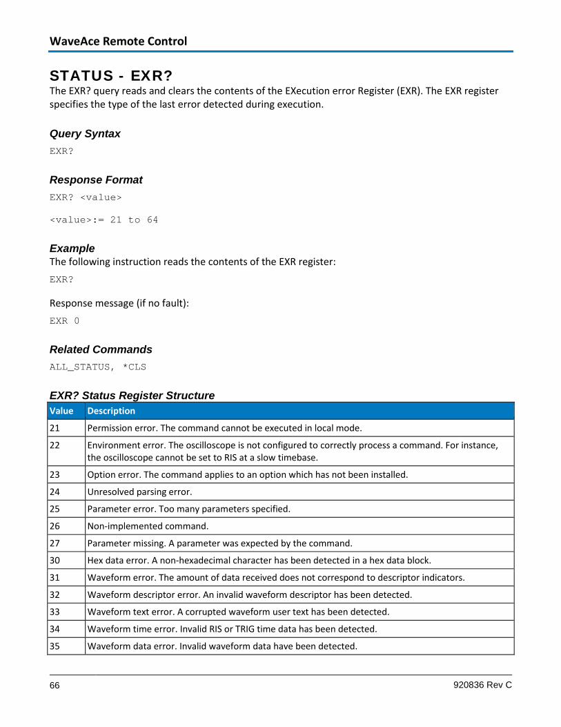
WaveAce Remote Control
66 920836 Rev C
STATUS - EXR? The EXR? query reads and clears the contents of the EXecution error Register (EXR). The EXR register specifies the type of the last error detected during execution.
Query Syntax EXR?
Response Format EXR? <value>
<value>:= 21 to 64
Example The following instruction reads the contents of the EXR register: EXR?
Response message (if no fault): EXR 0
Related Commands ALL_STATUS, *CLS
EXR? Status Register Structure Value Description
21 Permission error. The command cannot be executed in local mode.
22 Environment error. The oscilloscope is not configured to correctly process a command. For instance, the oscilloscope cannot be set to RIS at a slow timebase.
23 Option error. The command applies to an option which has not been installed.
24 Unresolved parsing error.
25 Parameter error. Too many parameters specified.
26 Non-implemented command.
27 Parameter missing. A parameter was expected by the command.
30 Hex data error. A non-hexadecimal character has been detected in a hex data block.
31 Waveform error. The amount of data received does not correspond to descriptor indicators.
32 Waveform descriptor error. An invalid waveform descriptor has been detected.
33 Waveform text error. A corrupted waveform user text has been detected.
34 Waveform time error. Invalid RIS or TRIG time data has been detected.
35 Waveform data error. Invalid waveform data have been detected.
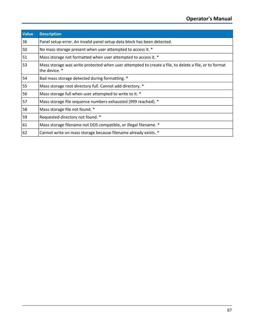
Operator's Manual
67
Value Description
36 Panel setup error. An invalid panel setup data block has been detected.
50 No mass storage present when user attempted to access it. *
51 Mass storage not formatted when user attempted to access it. *
53 Mass storage was write protected when user attempted to create a file, to delete a file, or to format the device. *
54 Bad mass storage detected during formatting. *
55 Mass storage root directory full. Cannot add directory. *
56 Mass storage full when user attempted to write to it. *
57 Mass storage file sequence numbers exhausted (999 reached). *
58 Mass storage file not found. *
59 Requested directory not found. *
61 Mass storage filename not DOS compatible, or illegal filename. *
62 Cannot write on mass storage because filename already exists. *

WaveAce Remote Control
68 920836 Rev C
STATUS - INR? The INR? query reads and clears the contents of the INternal state change Register (INR). The INR register records the completion of various internal operations and state transitions.
Query Syntax INR?
Response Format INR <value>
<value>:= 0 to 65535
Sample Response message:
INR 1026
Related Commands
ALL_STATUS, *CLS
INR Status Register Structure Bit Value Description
15 0 - Reserved for future use.
14 16384 1 - Probe was changed.
13 8192 1 - Trigger is ready.
12 4096 1 - Pass/Fail test detected desired outcome.
11 2048 1 - Waveform processing has terminated in trace F4.
10 1024 1 - Waveform processing has terminated in trace F3.
9 512 1 - Waveform processing has terminated in trace F2.
8 256 1 - Waveform processing has terminated in trace F1.
7 128 1 - A disk exchange has been detected.
6 64 1 - Disk has become full in AutoStore Fill mode.
5 32 0 - Reserved for Teledyne LeCroy use.
4 16 1 - Segment of a sequence waveform has been acquired in acquisition memory but not yet read out into the main memory.
3 8 1 - Time-out has occurred in a data block transfer.
2 4 1 - Return to the local state is detected.
1 2 1 - Screen dump has terminated.
0 1 1 - New signal acquired in acquisition memory and read out to the main memory.
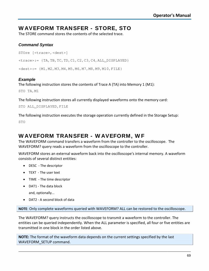
Operator's Manual
69
WAVEFORM TRANSFER - STORE, STO The STORE command stores the contents of the selected trace.
Command Syntax
STOre [<trace>,<dest>]
<trace>:= {TA,TB,TC,TD,C1,C2,C3,C4,ALL_DISPLAYED}
<dest>:= {M1,M2,M3,M4,M5,M6,M7,M8,M9,M10,FILE}
Example The following instruction stores the contents of Trace A (TA) into Memory 1 (M1): STO TA,M1
The following instruction stores all currently displayed waveforms onto the memory card: STO ALL_DISPLAYED,FILE
The following instruction executes the storage operation currently defined in the Storage Setup: STO
WAVEFORM TRANSFER - WAVEFORM, WF The WAVEFORM command transfers a waveform from the controller to the oscilloscope. The WAVEFORM? query reads a waveform from the oscilloscope to the controller.
WAVEFORM stores an external waveform back into the oscilloscope's internal memory. A waveform consists of several distinct entities:
• DESC - The descriptor
• TEXT - The user text
• TIME - The time descriptor
• DAT1 - The data block
and, optionally...
• DAT2 - A second block of data
NOTE: Only complete waveforms queried with WAVEFORM? ALL can be restored to the oscilloscope.
The WAVEFORM? query instructs the oscilloscope to transmit a waveform to the controller. The entities can be queried independently. When the ALL parameter is specified, all four or five entities are transmitted in one block in the order listed above.
NOTE: The format of the waveform data depends on the current settings specified by the last WAVEFORM_SETUP command.

WaveAce Remote Control
70 920836 Rev C
Command Syntax
<memory>:WaveForm ALL,<data_block>
<memory>:= {M1,M2,M3,M4,M5,M6,M7,M8,M9,M10}
<data_block>:= waveform data block.
Query Syntax
<trace>:WaveForm? <entity>
<trace>:= {TA,TB,TC,TD,C1,C2,C3,C4,M1,M2,M3,M4,M5,M6,M7,M8,M9,M10}
<entity>:= {DESC, TEXT, TIME, DAT1, DAT2, ALL}
If you do not provide a parameter, ALL is assumed.
Response Format
<trace>:WaveForm <entity>,<waveform_data_block>
TIP: It may be convenient to disable the response header if the waveform is to be restored. Refer to the COMM_HEADER, CHDR command topic for more information.
Example The following instruction reads the block DAT1 from Memory 1. M1:WF? DAT1
Related Commands
WAVEFORM_SETUP

Operator's Manual
71
WAVEFORM TRANSFER – WAVEFORM_SETUP, WFSU The WAVEFORM_SETUP command specifies the amount of data in a waveform to be transmitted to the controller. This is defined by the parameters: Sparsing, interval between data points; Number of Points, total number of points to be transmitted; First Point, the address of the first data point to be sent; Segment Number, which segment to be sent if the waveform was acquired in sequence mode.
The WAVEFORM_SETUP? query returns the transfer parameters currently in use.
Command Syntax WaveForm_SetUp SP,<sparsing>,NP,<number of transferred points>,FP,<first point>,SN,<segment number>
<sparsing>:= 0 to n where 0 sends all data points n sends every nth data point
<number of transferred points>:= 0 to n where 0 sends all data points n sends a maximum of n data points.
<first points>:= 0 to n where 0 sends the first data point n sends n+1.
<segment number>:= 0 to n where 0 sends all segments n sends the nth segment.
NOTE: After power-on, all values are set to 0 (i.e., entire waveforms transmitted without sparsing).
Query Syntax WaveForm_SetUp?
Response Format WaveForm_SetUp SP,<sparsing>,NP,<number>,FP,<point>,SN,<segment>
Example The following command specifies that every 3rd data point (SP=3) starting at address 200 (FP=200) in segment 23 (SN=23) should be transferred:
WFSU SP,3,FP,200,SN,23
Related Commands WAVEFORM

WaveAce Remote Control
72 920836 Rev C
Appendix: Waveform Template This section contains the Waveform Template describing the contents of the Waveform Descriptor produced by WF? DESC and WF? ALL queries. After the template, explanations detail the construction of floating point numbers from bytes in the descriptor, followed by program fragments showing a method of performing calculations.
Wave Descriptor Block WAVEDESC; Explanation < 0> DESCRIPTOR_NAME: string ; the first 8 chars are always WAVEDESC
;
< 16> TEMPLATE_NAME: string
;
< 32> COMM_TYPE: enum ; chosen by remote command COMM_FORMAT
_0 byte
_1 word
endenum
;
< 34> COMM_ORDER: enum
_0 HIFIRST
_1 LOFIRST
endenum
;
;
; The following variables of this basic wave descriptor block specify
; the block lengths of all blocks of which the entire waveform (as it is
; currently being read) is composed. If a block length is zero, this
; block is (currently) not present.
;
; Blocks and arrays that are present will be found in the same order

Operator's Manual
73
; as their descriptions below.
;
;BLOCKS :
;
< 36> WAVE_DESCRIPTOR: long ; length in bytes of block WAVEDESC
< 40> USER_TEXT: long ; length in bytes of block USERTEXT
< 44> RES_DESC1: long ;
;
;ARRAYS :
;
< 48> TRIGTIME_ARRAY: long ; length in bytes of TRIGTIME array
;
< 52> RIS_TIME_ARRAY: long ; length in bytes of RIS_TIME array
;
< 56> RES_ARRAY1: long ; an expansion entry is reserved
;
< 60> WAVE_ARRAY_1: long ; length in bytes of 1st simple
; data array. In transmitted waveform,
; represent the number of transmitted
; bytes in accordance with the NP
; parameter of the WFSU remote command
; and the used format (see COMM_TYPE).
;
< 64> WAVE_ARRAY_2: long ; length in bytes of 2nd simple
; data array
;

WaveAce Remote Control
74 920836 Rev C
< 68> RES_ARRAY2: long
< 72> RES_ARRAY3: long ; 2 expansion entries are reserved
;
; The following variables identify the instrument
;
< 76> INSTRUMENT_NAME: string
;
< 92> INSTRUMENT_NUMBER: long
;
< 96> TRACE_LABEL: string ; identifies the waveform.
;
<112> RESERVED1: word
<114> RESERVED2: word ; 2 expansion entries
;
; The following variables describe the waveform and the time at
; which the waveform was generated.
;
<116> WAVE_ARRAY_COUNT: long ; number of data points in the data
; array. If there are two data
; arrays (FFT or Extrema), this number
; applies to each array separately.
;
<120> PNTS_PER_SCREEN: long ; nominal number of data points
; on the screen
;
<124> FIRST_VALID_PNT: long ; count of number of points to skip
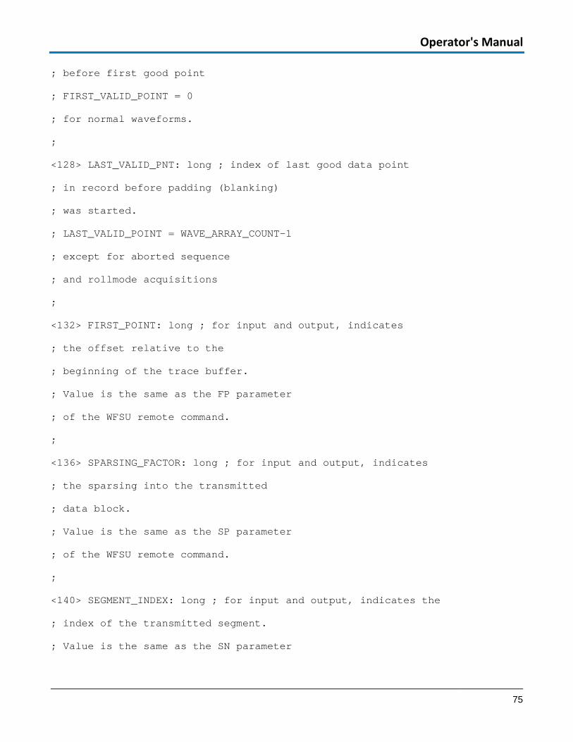
Operator's Manual
75
; before first good point
; FIRST_VALID_POINT = 0
; for normal waveforms.
;
<128> LAST_VALID_PNT: long ; index of last good data point
; in record before padding (blanking)
; was started.
; LAST_VALID_POINT = WAVE_ARRAY_COUNT-1
; except for aborted sequence
; and rollmode acquisitions
;
<132> FIRST_POINT: long ; for input and output, indicates
; the offset relative to the
; beginning of the trace buffer.
; Value is the same as the FP parameter
; of the WFSU remote command.
;
<136> SPARSING_FACTOR: long ; for input and output, indicates
; the sparsing into the transmitted
; data block.
; Value is the same as the SP parameter
; of the WFSU remote command.
;
<140> SEGMENT_INDEX: long ; for input and output, indicates the
; index of the transmitted segment.
; Value is the same as the SN parameter

WaveAce Remote Control
76 920836 Rev C
; of the WFSU remote command.
;
<144> SUBARRAY_COUNT: long ; for Sequence, acquired segment count,
; between 0 and NOM_SUBARRAY_COUNT
;
<148> SWEEPS_PER_ACQ: long ; for Average or Extrema,
; number of sweeps accumulated
; else 1
;
<152> POINTS_PER_PAIR: word ; for Peak Detect waveforms (which always
; include data points in DATA_ARRAY_1 and
; min/max pairs in DATA_ARRAY_2).
; Value is the number of data points for
; each min/max pair.
;
<154> PAIR_OFFSET: word ; for Peak Detect waveforms only
; Value is the number of data points by
; which the first min/max pair in
; DATA_ARRAY_2 is offset relative to the
; first data value in DATA_ARRAY_1.
;
<156> VERTICAL_GAIN: float
;
<160> VERTICAL_OFFSET: float ; to get floating values from raw data :
; VERTICAL_GAIN * data - VERTICAL_OFFSET
;

Operator's Manual
77
<164> MAX_VALUE: float ; maximum allowed value. It corresponds
; to the upper edge of the grid.
;
<168> MIN_VALUE: float ; minimum allowed value. It corresponds
; to the lower edge of the grid.
;
<172> NOMINAL_BITS: word ; a measure of the intrinsic precision
; of the observation: ADC data is 8 bit
; averaged data is 10-12 bit, etc.
;
<174> NOM_SUBARRAY_COUNT: word ; for Sequence, nominal segment count
; else 1
;
<176> HORIZ_INTERVAL: float ; sampling interval for time domain
; waveforms
;
<180> HORIZ_OFFSET: double ; trigger offset for the first sweep of
; the trigger, seconds between the
; trigger and the first data point
;
<188> PIXEL_OFFSET: double ; needed to know how to display the
; waveform
;
<196> VERTUNIT: unit_definition ; units of the vertical axis
;
<244> HORUNIT: unit_definition ; units of the horizontal axis

WaveAce Remote Control
78 920836 Rev C
;
<292> HORIZ_UNCERTAINTY: float ; uncertainty from one acquisition to the
; next, of the horizontal offset in seconds
;
<296> TRIGGER_TIME: time_stamp ; time of the trigger
;
<312> ACQ_DURATION: float ; duration of the acquisition (in sec)
; in multi-trigger waveforms.
; (e.g. sequence, RIS, or averaging)
;
<316> RECORD_TYPE: enum
_0 single_sweep
_1 interleaved
_2 histogram
_3 graph
_4 filter_coefficient
_5 complex
_6 extrema
_7 sequence_obsolete
_8 centered_RIS
_9 peak_detect
endenum
;
<318> PROCESSING_DONE: enum
_0 no_processing
_1 fir_filter

Operator's Manual
79
_2 interpolated
_3 sparsed
_4 autoscaled
_5 no_result
_6 rolling
_7 cumulative
endenum
;
<320> RESERVED5: word ; expansion entry
;
<322> RIS_SWEEPS: word ; for RIS, the number of sweeps
; else 1
;
; The following variables describe the basic acquisition
; conditions used when the waveform was acquired
;
<324> TIMEBASE: enum
_0 1_ps/div
_1 2_ps/div
_2 5_ps/div
_3 10_ps/div
_4 20_ps/div
_5 50_ps/div
_6 100_ps/div
_7 200_ps/div
_8 500_ps/div

WaveAce Remote Control
80 920836 Rev C
_9 1_ns/div
_10 2_ns/div
_11 5_ns/div
_12 10_ns/div
_13 20_ns/div
_14 50_ns/div
_15 100_ns/div
_16 200_ns/div
_17 500_ns/div
_18 1_us/div
_19 2_us/div
_20 5_us/div
_21 10_us/div
_22 20_us/div
_23 50_us/div
_24 100_us/div
_25 200_us/div
_26 500_us/div
_27 1_ms/div
_28 2_ms/div
_29 5_ms/div
_30 10_ms/div
_31 20_ms/div
_32 50_ms/div
_33 100_ms/div
_34 200_ms/div

Operator's Manual
81
_35 500_ms/div
_36 1_s/div
_37 2_s/div
_38 5_s/div
_39 10_s/div
_40 20_s/div
_41 50_s/div
_42 100_s/div
_43 200_s/div
_44 500_s/div
_45 1_ks/div
_46 2_ks/div
_47 5_ks/div
_100 EXTERNAL
endenum
;
<326> VERT_COUPLING: enum
_0 DC_50_Ohms
_1 ground
_2 DC_1MOhm
_3 ground
_4 AC,_1MOhm
endenum
;
<328> PROBE_ATT: float
;
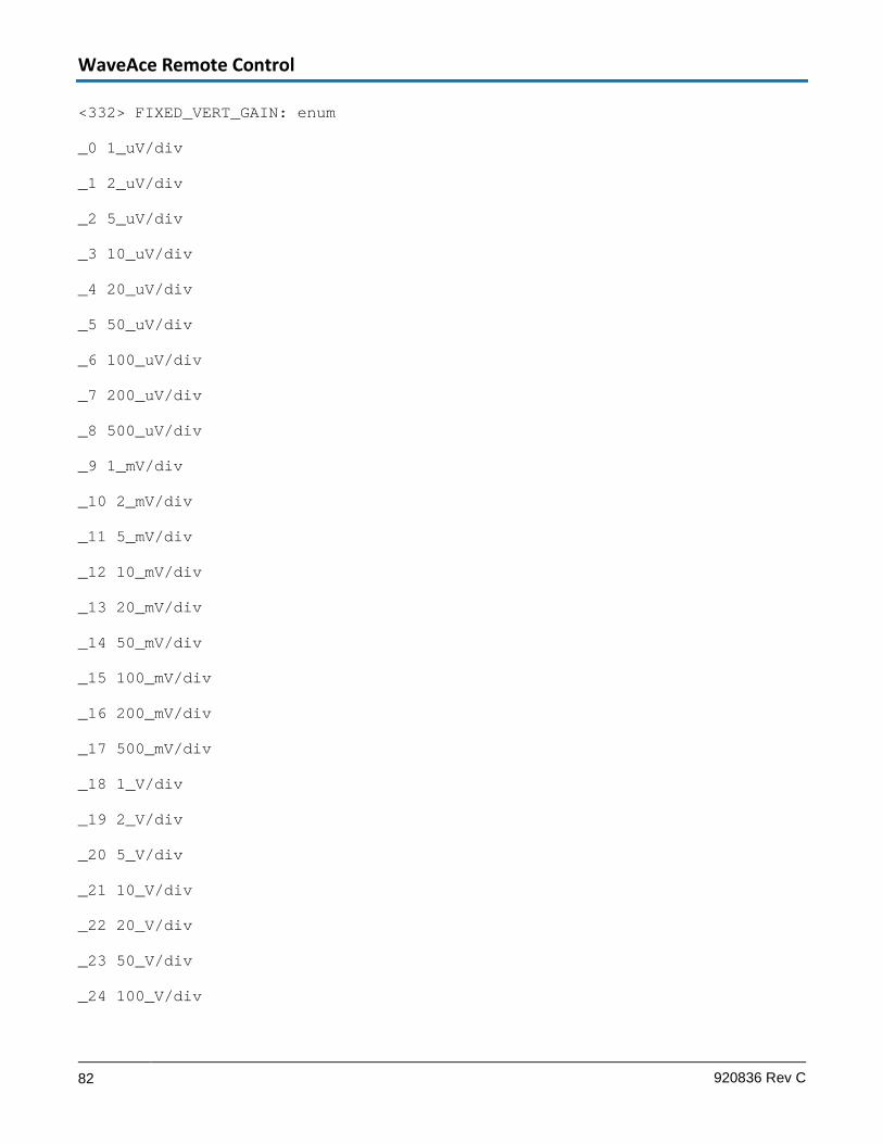
WaveAce Remote Control
82 920836 Rev C
<332> FIXED_VERT_GAIN: enum
_0 1_uV/div
_1 2_uV/div
_2 5_uV/div
_3 10_uV/div
_4 20_uV/div
_5 50_uV/div
_6 100_uV/div
_7 200_uV/div
_8 500_uV/div
_9 1_mV/div
_10 2_mV/div
_11 5_mV/div
_12 10_mV/div
_13 20_mV/div
_14 50_mV/div
_15 100_mV/div
_16 200_mV/div
_17 500_mV/div
_18 1_V/div
_19 2_V/div
_20 5_V/div
_21 10_V/div
_22 20_V/div
_23 50_V/div
_24 100_V/div

Operator's Manual
83
_25 200_V/div
_26 500_V/div
_27 1_kV/div
endenum
;
<334> BANDWIDTH_LIMIT: enum
_0 off
_1 on
endenum
;
<336> VERTICAL_VERNIER: float
;
<340> ACQ_VERT_OFFSET: float
;
<344> WAVE_SOURCE: enum
_0 CHANNEL_1
_1 CHANNEL_2
_2 CHANNEL_3
_3 CHANNEL_4
_9 UNKNOWN
endenum
;
/00 ENDBLOCK
;
;
USERTEXT: BLOCK

WaveAce Remote Control
84 920836 Rev C
;
; Explanation of the descriptor block USERTEXT at most 160 bytes long.
;
;
< 0> TEXT: text ; a list of ASCII characters
;
/00 ENDBLOCK
;
;
TRIGTIME: ARRAY
;
; Explanation of the trigger time array TRIGTIME.
; This optional time array is only present with SEQNCE waveforms.
; The following data block is repeated for each segment which makes up
; the acquired sequence record.
;
< 0> TRIGGER_TIME: double ; for sequence acquisitions,
; time in seconds from first
; trigger to this one
;
< 8> TRIGGER_OFFSET: double ; the trigger offset is in seconds
; from trigger to zeroth data point
;
/00 ENDARRAY
;
;
Operator's Manual
85
RISTIME: ARRAY
;
; Explanation of the random-interleaved-sampling (RIS) time array RISTIME.
; This optional time array is only present with RIS waveforms.
; This data block is repeated for each sweep which makes up the RIS record
;
< 0> RIS_OFFSET: double ; seconds from trigger to zeroth
; point of segment
;
/00 ENDARRAY
;
;
DATA_ARRAY_1: ARRAY
;
; Explanation of the data array DATA_ARRAY_1.
; This main data array is always present. It is the only data array for
; most waveforms.
; The data item is repeated for each acquired or computed data point
; of the first data array of any waveform.
;
< 0> MEASUREMENT: data ; the actual format of a data is
; given in the WAVEDESC descriptor
; by the COMM_TYPE variable.
;
/00 ENDARRAY
;
WaveAce Remote Control
86 920836 Rev C
;
DATA_ARRAY_2: ARRAY
;
; Explanation of the data array DATA_ARRAY_2.
; This is an optional secondary data array for special types of waveforms:
; Complex FFT imaginary part (real part in DATA_ARRAY_1)
; Extrema floor trace (roof trace in DATA_ARRAY_1)
; Peak Detect min/max pairs (data values in DATA_ARRAY_1)
; In the first 2 cases, there is exactly one data item in DATA_ARRAY_2 for
; each data item in DATA_ARRAY_1.
; In Peak Detect waveforms, there may be fewer data values in DATA_ARRAY_2,
; as described by the variable POINTS_PER_PAIR.
;
< 0> MEASUREMENT: data ; the actual format of a data is
; given in the WAVEDESC descriptor
; by the COMM_TYPE variable.
;
/00 ENDARRAY
;
;
SIMPLE: ARRAY
;
; Explanation of the data array SIMPLE.
; This data array is identical to DATA_ARRAY_1. SIMPLE is an accepted
; alias name for DATA_ARRAY_1.
;

Operator's Manual
87
< 0> MEASUREMENT: data ; the actual format of a data is
; given in the WAVEDESC descriptor
; by the COMM_TYPE variable.
;
/00 ENDARRAY
;
;
DUAL: ARRAY
;
; Explanation of the DUAL array.
; This data array is identical to DATA_ARRAY_1, followed by DATA_ARRAY_2.
; DUAL is an accepted alias name for the combined arrays DATA_ARRAY_1 and
; DATA_ARRAY_2 (e.g. real and imaginary parts of an FFT).
;
< 0> MEASUREMENT_1: data ; data in DATA_ARRAY_1.
;
< 0> MEASUREMENT_2: data ; data in DATA_ARRAY_2.
;
/00 ENDARRAY
;
;
00 ENDTEMPLATE

WaveAce Remote Control
88 920836 Rev C
Oscilloscope's TMPL? Query Response This template is the oscilloscope's response to a TMPL? query:/00
000000 LECROY_2_3: TEMPLATE
8 66 111
;
; Explanation of the formats of waveforms and their descriptors on the
; Teledyne LeCroy Digital Oscilloscopes,
; Software Release 8.1.0, 98/09/29.
;
; A descriptor and/or a waveform consists of one or several logical data
; blocks whose formats are explained below.
; Usually, complete waveforms are read: at the minimum they consist of
; the basic descriptor block WAVEDESC a data array block.
; Some more complex waveforms, e.g. Extrema data or the results of a
; Fourier transform, may contain several data array blocks.
; When there are more blocks, they are in the following sequence:
; the basic descriptor block WAVEDESC
; the history text descriptor block USERTEXT (may or may not be present)
; the time array block (for RIS and sequence acquisitions only)
; data array block
; auxiliary or second data array block
;
; In the following explanation, every element of a block is described by
; a single line in the form
;
; <byte position> <variable name>: <variable type> ; <comment>

Operator's Manual
89
;
; where
;
; <byte position> = position in bytes (decimal offset) of the variable,
; relative to the beginning of the block.
;
; <variable name> = name of the variable.
;
; <variable type> = string up to 16-character name
; terminated with a null byte
; byte 08-bit signed data value
; word 16-bit signed data value
; long 32-bit signed data value
; float 32-bit IEEE floating point value
; with the format shown below
; 31 30 .. 23 22 ... 0 bit position
; s exponent fraction
; where
; s = sign of the fraction
; exponent = 8 bit exponent e
; fraction = 23 bit fraction f
; and the final value is
; (-1)**s * 2**(e-127) * 1.f
; double 64-bit IEEE floating point value
; with the format shown below
; 63 62 .. 52 51 ... 0 bit position
WaveAce Remote Control
90 920836 Rev C
; s exponent fraction
; where
; s = sign of the fraction
; exponent = 11 bit exponent e
; fraction = 52 bit fraction f
; and the final value is
; (-1)**s * 2**(e-1023) * 1.f
; enum enumerated value in the range 0 to N
; represented as a 16-bit data value.
; The list of values follows immediately.
; The integer is preceded by an _.
; time_stamp double precision floating point number,
; for the number of seconds and some bytes
; for minutes, hours, days, months and year.
;
; double seconds (0 to 59)
; byte minutes (0 to 59)
; byte hours (0 to 23)
; byte days (1 to 31)
; byte months (1 to 12)
; word year (0 to 16000)
; word unused
; There are 16 bytes in a time field.
; data byte, word or float, depending on the
; read-out mode reflected by the WAVEDESC
; variable COMM_TYPE, modifiable via the
Operator's Manual
91
; remote command COMM_FORMAT.
; text arbitrary length text string
; (maximum 160)
; unit_definition a unit definition consists of a 48 character
; ASCII string terminated with a null byte
; for the unit name.

WaveAce Remote Control
92 920836 Rev C
Decoding Floating Point Numbers Single precision values are held in four bytes. If these are arranged in decreasing value order we get the following bits:
bit 31, bit 30, bit 29, bit 28 . . . . . bit 3, bit 2, bit 1, bit 0
NOTE: If the byte order command CORD is set for low byte first, the bytes as received in a waveform descriptor are received in reverse order. However, within a byte the bits keep their order, highest at the left, as expected.
From these bits we are to construct three numbers that are to be multiplied together: S X E X F constructed as follows:
S = (-1)sE = 2(e - 127) F = 1 + f
S, E, and F are calculated directly from the 32 bits. The following diagram illustrates the calculation of the vertical gain example:

Operator's Manual
93
In a way not following the byte boundaries, bits are then segregated as follows:
31, 30, 29 . . . . 24, 23, 22, 21 . . . . 2, 1, 0
Sign exponent bits fractional bits
bit 0.5, 0.25, 0.125 . . .
The sign bit s is 1 for a negative number and 0 for a positive number, so it is easy to construct the sign from this:
S = (-1)^s
The 8 exponent bits have the following values: bit 23 is worth 1, bit 24 is worth 2 . . . bit 29 64, bit 3 128, so the resulting number can range from 0 to 28 - 1, which is 255.
127 is then subtracted from this value e creating a range from -127 to +128. This is then used as an exponent to raise two to a power that is 2^e, to create a value E.
Then we have to create the multiplying number. The values of the 23 bits are as follows: bit 22 is worth 0.5, 21 is worth 0.25, 20 is worth 0.125, 19 is worth 0.0625 . . . .
When all the bits are added together, we obtain a positive number f that can be very close to one, differing from it only by the value of the smallest bit, if all the bits are ones. (Generally the value will be much less than one.) Then we add one to the result, obtaining 1 + f = F. The use of the added one extends the dynamic range of the data. Another way of calculating f is to take the 23-bit number at face value, and divide it by 2^24.
Finally we multiply together the sign, the value E, and the value F to create the final result:
Result = (-1)^s x 2^(e-127) x (1 + f) = S x E x F