Embed Size (px)
Citation preview
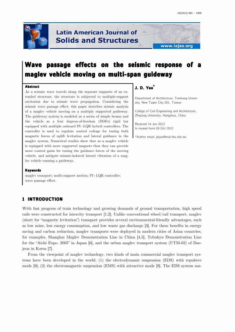
10(2013) 981 – 1000
Abstract As a seismic wave travels along the separate supports of an ex-tended structure, the structure is subjected to multiple-support excitation due to seismic wave propagation. Considering the seismic wave passage effect, this paper describes seismic analysis of a maglev vehicle moving on a multiply supported gudieway. The guideway system is modeled as a series of simple beams and the vehicle as a four degrees-of-freedom (DOFs) rigid bar equipped with multiple onboard PI+LQR hybrid controllers. The controller is used to regulate control voltage for tuning both magnetic forces of uplift levitation and lateral guidance in the maglev system. Numerical studies show that as a maglev vehicle is equipped with more supported magnets then they can provide more control gains for tuning the guidance forces of the moving vehicle, and mitigate seismic-induced lateral vibration of a mag-lev vehicle running a guideway. Keywords maglev transport; multi-support motion; PI+LQR controller; wave passage effect.
Wave passage effects on the seismic response of a maglev vehicle moving on multi-span guideway
1 INTRODUCTION
With fast progress of train technology and growing demands of ground transportation, high speed rails were constructed for intercity transport [1,2]. Unlike conventional wheel/rail transport, maglev (short for “magnetic levitation”) transport provides several environmental-friendly advantages, such as low noise, less energy consumption, and low waste gas discharge [3]. For these benefits in energy saving and carbon reduction, maglev transports were deployed in modern cities of Asian countries, for examples, Shanghai Maglev Demonstration Line in China [4,5], Tobukyu Demonstration Line for the “Aichi Expo. 2005” in Japan [6], and the urban maglev transport system (UTM-02) of Dae-jeon in Korea [7].
From the viewpoint of maglev technology, two kinds of main commercial maglev transport sys-tems have been developed in the world: (1) the electrodynamic suspension (EDS) with repulsive mode [8]; (2) the electromagnetic suspension (EMS) with attractive mode [9]. The EDS system sus-
J. D. Yau* Department of Architecture, Tamkang Univer-sity, New Taipei City 251, Taiwan College of Civil Engineering and Architecture, Zhejiang University, Hangzhou, China Received 14 Jun 2012 In revised form 09 Oct 2012 *Author email: [email protected]
982 J. D. Yau / Wave passage effects on the seismic response of a maglev vehicle moving on multi-span guideway
Latin American Journal of Solids and Structures 10(2013) 981 – 1000
pends a train above its guide-rail using magnetic repulsive forces to take the train off the U-shaped guideway. One feature of EDS-type maglev trains is that its magnetic levitation is workable only at high speeds. But the EMS system can lift a train up using attractive forces by the supported mag-nets between vehicle’s levitation frame and guide-rail at any speed, which is the major difference from the EDS system.
Concerning the types of uplift forces to levitate a maglev train running on a guideway, Cai et al. [10] revealed that a concentrated-load vehicle model might gives rise to larger response on both guideway deflections and vehicle accelerations than a distributed-load vehicle model. In addition, Cai and Chen [11] provided a literature review for various aspects of the dynamic characteristics, magnetic suspension systems, vehicle stability, suspension control laws of maglev/guideway cou-pling systems. Zheng et al. [12,13] developed two kinds of maglev vehicle/guideway coupling models to investigate the dynamic problems of divergence, flutter, and collision on the dynamic stability of a maglev-vehicle traveling on a flexible guideway. Zhao and Zhai [14] modeled the levitation forces as an equivalent spring to investigate vertical random response and ride quality of a maglev vehicle traveling on elevated guideways. Yau [15-19,21] and Yang and Yau [20] carried out a series of dy-namic investigations of maglev vehicles traveling over flexible guideways [15], including vibration control of moving vehicle [16], influence of ground settlement [17], horizontal earthquake-induced vibration [18], aerodynamic vibration [19,21], and dynamic interaction of vehicle-guideway system with soil-foundation [20].
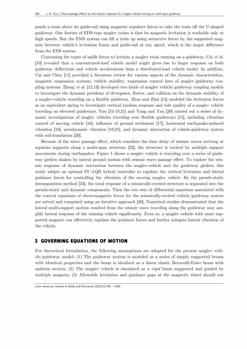
Because of the wave passage effect, which considers the time delay of seismic waves arriving at separate supports along a multi-span structure [22], the structure is excited by multiple support movements during earthquakes. Figure 1 shows a maglev vehicle is traveling over a series of guide-way girders shaken by lateral ground motion with seismic wave passage effect. To explore the seis-mic response of dynamic interaction between the maglev-vehicle and the guideway girders, this study adopts an optimal PI+LQR hybrid controller to regulate the vertical levitation and lateral guidance forces for controlling the vibration of the moving maglev vehicle. By the pseudo-static decomposition method [23], the total response of a seismically-excited structure is separated into the pseudo-static and dynamic components. Then the two sets of differential equations associated with the control equations of electromagnetic forces for the seismically-excited vehicle/guideway system are solved and computed using an iterative approach [20]. Numerical studies demonstrated that the lateral multi-support motion resulted from the seismic wave traveling along the guideway may am-plify lateral response of the running vehicle significantly. Even so, a maglev vehicle with more sup-ported magnets can effectively regulate the guidance forces and further mitigate lateral vibration of the vehicle.
2 GOVERNING EQUATIONS OF MOTION
For theoretical formulation, the following assumptions are adopted for the present maglev vehi-cle/guideway model: (1) The guideway system is modeled as a series of simply supported beams with identical properties and the beam is idealized as a linear elastic Bernoulli-Euler beam with uniform section; (2) The maglev vehicle is simulated as a rigid beam supported and guided by multiple magnets; (3) Allowable levitation and guidance gaps at the magnetic wheel should not
J. D. Yau / Wave passage effects on the seismic response of a maglev vehicle moving on multi-span guideway 983
Latin American Journal of Solids and Structures 10(2013) 981 – 1000
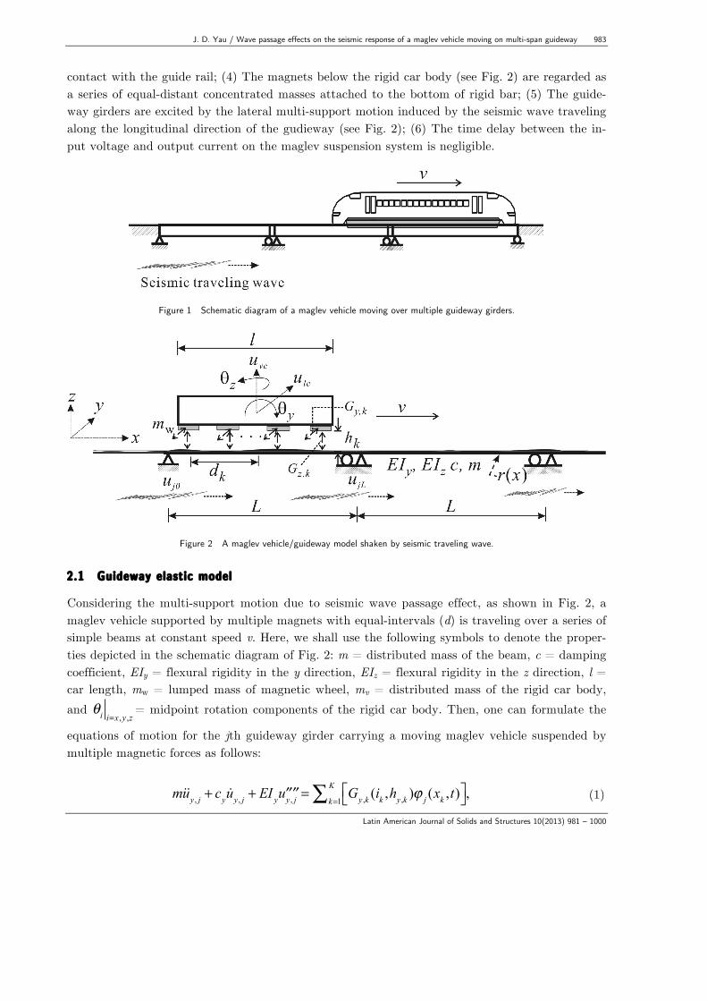
contact with the guide rail; (4) The magnets below the rigid car body (see Fig. 2) are regarded as a series of equal-distant concentrated masses attached to the bottom of rigid bar; (5) The guide-way girders are excited by the lateral multi-support motion induced by the seismic wave traveling along the longitudinal direction of the gudieway (see Fig. 2); (6) The time delay between the in-put voltage and output current on the maglev suspension system is negligible.
Figure 1 Schematic diagram of a maglev vehicle moving over multiple guideway girders.
Figure 2 A maglev vehicle/guideway model shaken by seismic traveling wave. 2.1 Guideway elastic model
Considering the multi-support motion due to seismic wave passage effect, as shown in Fig. 2, a maglev vehicle supported by multiple magnets with equal-intervals (d) is traveling over a series of simple beams at constant speed v. Here, we shall use the following symbols to denote the proper-ties depicted in the schematic diagram of Fig. 2: m = distributed mass of the beam, c = damping coefficient, EIy = flexural rigidity in the y direction, EIz = flexural rigidity in the z direction, l = car length, mw = lumped mass of magnetic wheel, mv = distributed mass of the rigid car body, and θi i=x,y ,z= midpoint rotation components of the rigid car body. Then, one can formulate the
equations of motion for the jth guideway girder carrying a moving maglev vehicle suspended by multiple magnetic forces as follows:
muy , j + cy uy , j + EI y ′′′′uy , j = Gy ,k (ik ,hy ,k )ϕ j (xk ,t)⎡⎣ ⎤⎦k=1
K∑ , (1)
984 J. D. Yau / Wave passage effects on the seismic response of a maglev vehicle moving on multi-span guideway
Latin American Journal of Solids and Structures 10(2013) 981 – 1000
muz , j + cz uz , j + EIz ′′′′uz , j = p0 − Gz ,k (ik ,hz ,k )ϕ j (xk ,t)⎡⎣ ⎤⎦k=1
K∑ , (2)
and
ϕ j (xk ,t) = δ x − xk( ) H t − tk −( j −1)Lv
⎛⎝⎜
⎞⎠⎟− H t − tk −
jLv
⎛⎝⎜
⎞⎠⎟
⎡
⎣⎢
⎤
⎦⎥ (3)
together with the following boundary conditions with lateral (y-direction) support movements:
uy , j (0,t) = uyj0 (t),uy , j (L,t) = uyjL (t),
EIz ′′uz , j (0,t) = EIz ′′uz , j (L,t) = 0, (4)
uz , j (0,t) = uz , j (L,t) = 0,
EI y ′′uy , j (0,t) = EI y ′′uy , j (L,t) = 0, (5)
where (•) ' = ∂(•) / ∂x , (•) = ∂(•) / ∂t , uz,j(x,t) = vertical deflection of the jth span, uy,j(x,t) = lateral deflection of the jth span, L = span length, K = number of magnets attached to the rigid levitation frame, δ (•)= Dirac's delta function, H(t) = unit step function, k = 1, 2, 3, …, Kth moving magnetic wheel on the beam, tk = (k - 1)d/v = arrival time of the kth magnetic wheel into the beam, xk = position of the k-th magnetic wheel on the guide-way, and (Gy,k, Gz,k) = lat-eral guidance and uplift levitation forces of the kth lumped magnet in the vertical and lateral directions. 2.2 Magnetic forces of uplift levitation and lateral guidance
As a maglev vehicle moves over guideway shaken by horizontal earthquakes with lateral ground motion, as shown in Fig.2, the lateral support movements to the guideway would affect the riding comfort and maneuverability of the moving vehicle. Thus, guidance forces tuned by the maglev system need to control the lateral motion of the moving maglev vehicle. This study adopts the lat-eral guidance force (Gy,k) and the uplift levitation force (Gz,k) proposed by Aldo and Alfred [24] to keep and guide the k-th magnet of the vehicle. They are expressed as
Gy ,k =κ 0ik (t)hz ,k (t)
⎛
⎝⎜
⎞
⎠⎟
2
κ z ,k (6)
J. D. Yau / Wave passage effects on the seismic response of a maglev vehicle moving on multi-span guideway 985
Latin American Journal of Solids and Structures 10(2013) 981 – 1000
Gz ,k =κ 0ik (t)hz ,k (t)
⎛
⎝⎜
⎞
⎠⎟
2
1−κ y ,k( ) (7)
where κ y ,k and κ z ,k represent induced guidance factors and they are given by,
κ y ,k =χk × hy ,kW (1+ χk )
,κ z ,k =χk × hz ,kW (1+ χk )
(8)
In Eqs. (6)-(7), κ 0 = µ0N0
2A0 / 4 = coupling factor, χk = πhy ,k / 4hz ,k , W = pole width, µ0=
vacuum permeability, N0 = number of turns of the magnet windings, A0 = pole face area, in (t) = i0 + ιn (t) = electric current, ιn (t)= deviation of current, and (i0, hy0, hz0) = desired current
and air gaps around a specified nominal operating point of the maglev wheels at static equilibrium. And the uplift levitation (hy,k) and lateral guidance (hz,k) gaps are respectively given by:
hy ,k (t) = hy0 + ul ,k (t) − uy , j (xk ), ul ,k (t) = ulc (t) + dkθ z (9)
(10) where (ul,k, uv,k) = displacements of the kth magnetic wheel in the y and z directions, (ulc, uvc) = midpoint displacements of the rigid car, (θ y ,θ z ) = midpoint rotations of the rigid car, r(x) = ir-
regularity of guideway, and dk = location of the kth magnetic wheel to the midpoint of the rigid beam.
As indicated in Eqs. (6)-(8), the motion-dependent nature and guidance factors (κ y ,k ,κ z ,k ) dominate the control forces of the maglev vehicle-guideway system. Next, the equations of motion of the 4-DOFs tigid maglev vehicle (see Fig. 2) are written as
M0ulc = g(t) + Gy ,kk=1
K∑ , IT θ z = g(t)× l + Gy ,kdk⎡⎣ ⎤⎦k=1
K∑ (11)
M0uvc = − p0 + Gz ,kk=1
K∑ , IT θ y = − Gz ,kdk⎡⎣ ⎤⎦k=1
K∑ (12)
in which M0 = mvl+Kmw = lumped mass of the vehicle, g(t) = control force to tune the lateral re-sponse of the maglev vehicle, IT = total mass moment of inertia of the rigid car, and p0 = M0g= lumped weight of the maglev vehicle. 3 LATERAL VIBRATION CONTROL BASED ON LQR ALGORITHM
LQR (Linear Quadratic Regulation) algorithm has been widely used in optimal control because of simplicity, reliability, robustness, and stability in a closed-loop system [25].Thus, the equations of
, 0 , , ,( ) ( ) ( ) ( ), ( ) ( )z k z v k z j k k v k vc k yh t h u t u x r x u t u t d θ= + − + = −
986 J. D. Yau / Wave passage effects on the seismic response of a maglev vehicle moving on multi-span guideway
Latin American Journal of Solids and Structures 10(2013) 981 – 1000
lateral motion for the maglev vehicle in Eqs. (11) and (12) are rewritten as
M0ulc = g(t) + f (t), f (t) = Gy ,k⎡⎣ ⎤⎦k=1
K∑ (13)
IT θ z = g(t)l +M(t), M(t) = Gy ,kdk⎡⎣ ⎤⎦k=1
K∑ (14)
It is noted that this study regards the control moment g(t)l exerting at the maglev vehicle in z-direction of Eqs. (14) is proportional to the control force g(t). 3.1 Determination of tuning parameters
Since Eqs. (13) and (14) are un-coupled each other, introducing the state space of
y = ulc ulc into Eq. (13) yields the following matrix equation
{ y}= [A]{y}+{B}g(t) +{C} f (t)
[A] = 0 10 0
⎡
⎣⎢
⎤
⎦⎥ , {B}= 0
1/M 0
⎧⎨⎪
⎩⎪
⎫⎬⎪
⎭⎪,
{C}= 01/M 0
⎧⎨⎪
⎩⎪
⎫⎬⎪
⎭⎪,g(t) = G⎡⎣ ⎤⎦ y{ }
(15)
where {y} = <y>T and [G] represents the control gain matrix. In this control algorithm, the con-trol force g(t) is determined by minimizing the following quadratic cost index [25]
J = {y}T [Q]{y}+ Rg 2⎡⎣ ⎤⎦0
t f∫ dt (16)
Here, [Q] is a symmetric positive semi-definite weighting matrix for the performance of a
structural system and R the weighting parameter for the input control force. To minimize the performance index J in Eq. (16), the Riccati equation [25] is usually used to obtain the following Riccati matrix [P] and the control gain matrix [G], i.e.,
[P][A]− 1
2[P]{B}R−1{B}T [P]+ [A]T [P]+ 2[Q]= [0] (17)
[G] = −12R−1[B]T [P] (18)
In this study, the weighting matrix [Q] is represented by
J. D. Yau / Wave passage effects on the seismic response of a maglev vehicle moving on multi-span guideway 987
Latin American Journal of Solids and Structures 10(2013) 981 – 1000
[Q] = kw 0
0 0
⎡
⎣⎢⎢
⎤
⎦⎥⎥
(19)
where kw represents the stiffness weighting parameter. The solution of the Riccati matrix [P] in Eq. (17)and the corresponding control gain g(t) in Eqs. (15) are respectively given as follows [31]:
[P] = 2M 0
kw / R × kw /M 0 kwR
kwR 2M 0R kwR
⎡
⎣
⎢⎢⎢
⎤
⎦
⎥⎥⎥ (20)
g(t) = [G]{y}= − 2M 0 kw / R × ulc + kw / R × ulc⎛⎝
⎞⎠ (21)
Let R = kw /Ψ
2 , the coefficient Ψ represents the relative importance of control performance
in response suppression [25]. Introducing the derived control force g(t) shown in Eq. (21) into Eqs. (13) and (14) yields the following equations for a controlled maglev-vehicle in lateral direc-tion:
M0ulc + 2M0Ψ × ulc +Ψulc = Gy ,k⎡⎣ ⎤⎦k=1
K∑ (22)
IT θ z + 2M0Ψ × l θ z +Ψlθ z = Gy ,kdk⎡⎣ ⎤⎦k=1
K∑ (23)
3.2 Determination of coupling factor
From the condition of static equilibrium for the suspended maglev vehicle with initial gaps of (hy0, hz0) in both lateral and vertical directions, respectively, one can obtain the following static electromagnetic force at the k-th magnetic wheel from Eqs. (6) and (7)
Gy0 =κ 0γ z02 χ0 × hz0 /W
1+ χ0
⎡
⎣⎢
⎤
⎦⎥ , (24)
Gz0 =κ 0γ z02 1−
χ0 × hy0 /W1+ χ0
⎡
⎣⎢⎢
⎤
⎦⎥⎥=p0K
(25)
Here, γ z0 = i0 / hz0 and χ0 = πhy0 / 4hz0 . To keep the maglev vehicle in static equilibrium at
988 J. D. Yau / Wave passage effects on the seismic response of a maglev vehicle moving on multi-span guideway
Latin American Journal of Solids and Structures 10(2013) 981 – 1000
initial lateral air gap of hy0, the control force required from the LQR-controlled magnetic actuator can be represented by:
Ψ0hy0 = Gy0⎡⎣ ⎤⎦k=1
K∑ (26)
where Ψ0 means the initial stiffness parameter tuned by the LQR-controlled magnetic actuator.
Solving the simultaneous equations of Eqs. (24)-(26) yields the following initial parameters
κ 0 =p0γ z0
−2
K1−
χ0 × hy0 /W1+ χ0
⎡
⎣⎢⎢
⎤
⎦⎥⎥
−1
(27)
with Ψ0 =π p0 / 4W
1+ (1− hy0 /W )χ0. For the special case of hy0 = 0, the coupling factor becomes
κ 0 = p0 / Kγ z02 , which is reduced to the case of a maglev vehicle at vertical static equilibrium
without initial lateral movement [16]. 3.3 Nonlinear actuator dynamics
As a maglev vehicle moves over guideway, the control actuator needs to provide additional gains for tuning the controller, let Ψ = Ψ0 +ψ and consider the initial lateral air gap of hy0, thus, the
equation of lateral motion for the moving maglev vehicle becomes
M0ulc + 2M0 (Ψ0 +ψ ) × ulc + Ψ0 +ψ( )ulc = −Ψ0hy0 + Gy ,k⎡⎣ ⎤⎦k=1
K∑ (28)
IT θ z + 2M0Ψ × l θ z +Ψlθ z = Gy ,kdk⎡⎣ ⎤⎦k=1
K∑ (29)
Here, ψ represents additional tuning stiffness gain as the maglev vehicle runs on the guide-
way subjected to lateral ground motion with traveling wave effect and ψ is set Ψ0 / 4 . 4 CONTROL EQUATION OF THE MAGLEV SUSPENSION SYSTEM
By the theory of electromagnetic circuits, the electromagnetic equation of magnet current and control voltage for the nth electric magnets in the maglev suspension system is given by
Γ0d(in / hz ,n )dt
+ R0in =Vn , (30)
J. D. Yau / Wave passage effects on the seismic response of a maglev vehicle moving on multi-span guideway 989
Latin American Journal of Solids and Structures 10(2013) 981 – 1000
where Γ0= initial inductance of the coil winding the suspension magnet, R0 = coil resistance of
electronic circuit, and Vn = control voltage. To control the levitation forces between the mgalev vehicle and guideway, an onboard PI control algorithm [26,27] is employed to regulate control voltage of the maglev system. Let us adopt the variable transformation as γ zn = in / hz ,n , the con-
trol voltage Vn can be expressed in terms of current error of en (= i0 / hz0 − in / hz ,n = γ z0 −γ zn ) in
the control process by using PI (Proportional-Integral) tuning algorithm as [27]
Vn = Kpen + Ki en dt0
t
∫ , (31)
where Kp = proportional gain and Ki = integral gain. In this study, the constant tuning gains (Kp, Ki) are used and determined by the Z-N tuning rule [26]. Then substituting Eq. (30) into Eq. (31) and differentiating this equation with respect to time, one can achieve the following differen-tial equation for control current error
Γ0en + (Kp + R0hz ,n ) en + (Ki + R0 hz ,n )en − R0γ z0 ( uvc − dk θ y ) = R0γ z0 r(xk ) − uzj( ). (32)
With the aid of the control error function en and the parameter 0 0 0/z zi hγ = at static equilibri-um, the equations of motion in Eqs. (11) and (12) for the controlled maglev vehicle become
M0ulc + 2M0 (Ψ0 +ψ ) × ulc + Ψ0 +ψ( )ulc = −Ψ0hy0 + ϒ0ekγ z0
−1⎛
⎝⎜⎞
⎠⎟
2 hz ,kχkW (1+ χk )⎡
⎣⎢⎢
⎤
⎦⎥⎥
⎡
⎣⎢⎢
⎤
⎦⎥⎥k=1
K
∑
I y θ z + 2M0 (Ψ0 +ψ ) × l θ z + Ψ0 +ψ( )lθ z = ϒ0ekγ z0
−1⎛
⎝⎜⎞
⎠⎟
2 hz ,kχkW (1+ χk )⎡
⎣⎢⎢
⎤
⎦⎥⎥dk
⎡
⎣⎢⎢
⎤
⎦⎥⎥k=1
K
∑ (33)
M0uvc = − p0 + ϒ0ekγ z0
−1⎛
⎝⎜⎞
⎠⎟
2
1−χk × hy ,kW (1+ χk )
⎡
⎣⎢⎢
⎤
⎦⎥⎥k=1
K
∑
IT θ y = ϒ0ekγ z0
−1⎛
⎝⎜⎞
⎠⎟
2
1−χk × hy ,kW (1+ χk )
⎛
⎝⎜
⎞
⎠⎟ dk
⎡
⎣⎢⎢
⎤
⎦⎥⎥k=1
K
∑ (34)
Where
ϒ0 =(1+ χ0 )p0 / K
1+ χ0 (1− hy0 /W ) (35)
990 J. D. Yau / Wave passage effects on the seismic response of a maglev vehicle moving on multi-span guideway
Latin American Journal of Solids and Structures 10(2013) 981 – 1000
Then combinating Eqs. (32)-(34) yields the following matrix equation of motion for the maglev vehicle equipped with onboard controllers
[mv ]{uv}+ [cv ,k ]{ uv}+ [kv ]{uv}={ fv}, (36) in which {uv} = displacement vector, {fv} = force vector, and ([kv], [cv], [mv]) means structural matrices of the maglev vehicle. 5 METHOD OF SOLUTION FOR FLEXIBLE GUIDEWAY GIRDERS
As shown in Eqs. (1) and (4), it is a differential equation associated with time-dependent bounda-ry conditions. The beam response to lateral multiple support excitations is divided into two parts [28]: (1) the pseudo-static displacement (Uy,j) due to the relative support motions of the beam, and (2) the dynamic component (udj) caused by the moving vehicle and seismic excitations. This approach is called pseudo-static decomposition method. Thus the total lateral displacement of the seismically-excited beam is represented by [16]
uy , j (x,t) =Uy , j (x,t) + udj (x,t)
Uy , j (x,t) = uyj0 (t) + uyjL (t) − uyj0 (t)( ) xLudj (x,t) = qy , jn (t)sin
nπ xLn=1
∑ ,
(37)
where the pseudo-static displacement of Uy,j(x,t) represents rigid body motion due to relative support motions of (uyj,0, uyj,L), and the dynamic deflection of udj(x, t) is induced by inertial effect of beam vibration. As shown in Eqs. (2) and (5), the vertical deflection uz , j (x,t) of the beam
with homogeneous boundary conditions can be approximated by [29]
, ,1
( , ) ( )sinz j z jnn
n xu x t q tLπ
=
=∑
(38)
Here, (qy,jn, qz,jn) are the generalized coordinates associated with the nth vibration mode in the
y and z directions of the jth span. By Galerkin’s method, the generalized equations of motion for the nth modal system of the jth
beam in the y (lateral) and z (vertical) directions are respectively given by:
mqy , jn + cy ,n qy ,n +mω yn2 qy , jn = py , jn −
2nπ
mΠ y , jn + cy ,n Π y , jn⎡⎣ ⎤⎦ , (39)
mqz , jn + cz ,n qy ,n +mω zn
2 qz , jn = pz , jn , (40)
J. D. Yau / Wave passage effects on the seismic response of a maglev vehicle moving on multi-span guideway 991
Latin American Journal of Solids and Structures 10(2013) 981 – 1000
where (cy ,n ,cz ,n )= the nth modal damping coefficient, (ω y ,n ,ω z ,n )= the nth natural frequency,
and
ω y ,n =nπl
⎛⎝⎜
⎞⎠⎟
2 EIzm,ω z ,n =
nπl
⎛⎝⎜
⎞⎠⎟
2 EI ym
Π y , jn = uyj0 (t) − uyjL (t)× cosnπ( ), (41)
The generalized magnetic forces of ( py , jn , pz , jn ) are given by
py , jn =2L
Gy ,kΦ jn (t)⎡⎣ ⎤⎦k=1
K
∑ , (42)
pz , jn =2L
−p0K
+Gz ,k⎛⎝⎜
⎞⎠⎟Φ jn (t)
⎡
⎣⎢⎢
⎤
⎦⎥⎥k=1
K
∑ (43)
and
Φ jn (t) = sinnπvL(t − tk )× H (t − tk −
( j −1)Lv
) − H t − tk −jLv
⎛⎝⎜
⎞⎠⎟
⎡
⎣⎢
⎤
⎦⎥ (44)
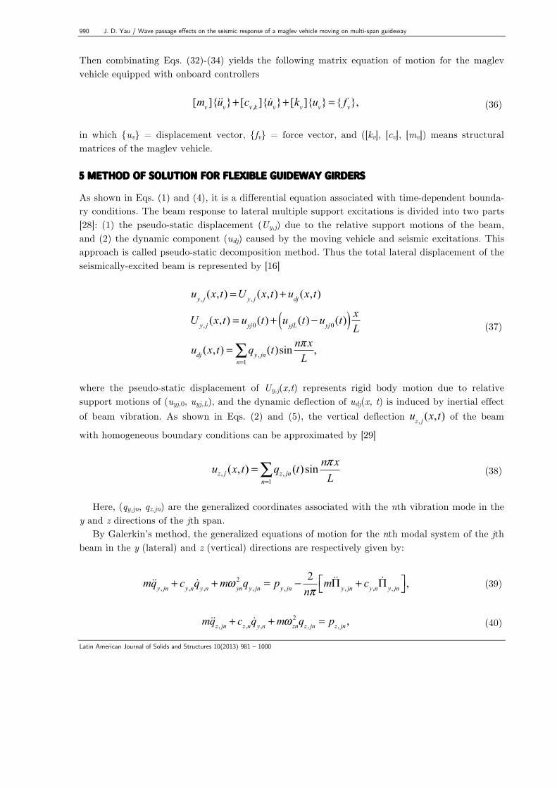
6 APPLICATIONS OF THE INCREMENTAL- ITERATIVE APPROACH
Because of motion-dependent and non-contact nature of electromagnetic forces, the nonlinear dynamic analysis of the maglev vehicle/guideway system needs to be solved by iterative method. The numerical procedure of incremental-iterative dynamic analysis conventionally involves three phases: predictor, corrector, and equilibrium checking. Detailed information about the incremen-tal-iterative procedure for nonlinear dynamic analysis of maglev vehicle/guieway interaction is available in references [15-21]. Figure 3 shows the analysis flow chart to carry out the nonlinear dynamic analysis for the vibration control and interaction responses of maglev vehicle/guideway system shaken by seismic loads. It is noted that (1) the structure matrices in Eqs. (36), (39), and (40) for the dynamic interactions of maglev vehicle/guideway system should be updated at each iteration; (2) the root mean square βtol of the sum of unbalanced forces for the maglev vehi-cle/guideway interaction system, that is,
βtol = (Δfvk ,t+Δti−1 )2
k=1...∑ + (Δpn,t+Δti−1 )2
n=1...∑⎡⎣ ⎤⎦1/2
(45)
is larger than a preset tolerance, say 10-3, iteration for removing the unbalanced forces involving
992 J. D. Yau / Wave passage effects on the seismic response of a maglev vehicle moving on multi-span guideway
Latin American Journal of Solids and Structures 10(2013) 981 – 1000
the two phases of predictor and corrector should be repeated. Here, Δpn,t+Δti−1 = the unbalanced
force between the external force pn,t+Δti−1 and the effective internal forces fn,t+Δt
i−1 for the n-th gener-
alized system at the i-th iteration of time t + Δt , and Δfvk ,t+Δti−1 = the unbalanced force for the k-
th maglev wheels to lift up the maglev vehicle.
Figure 3 Flow chart of incremental-iterative procedure 7 NUMERICAL INVESTIGATIONS
Figure 2 shows a maglev vehicle suspended by multiple magnets is traveling over a series of iden-tical guideway girders with constant speed v. The properties of the guideway girder and the mag-lev vehicle are listed in Tables 1 and 2, respectively. For comparison, let us consider two maglev vehicle models levitated by multiple magnetic wheels (see Table 2). They are named MG-1 and MG-2, respectively. Here, MG-1 represents the maglev vehicle levitated by 6 magnets and MG-2 by 16 magnets. To account for the random nature and characteristics of guide-rail irregularity in practice [4], the following power spectrum density (PSD) function used by the Federal Railroad Administration (FRA) [1] is given to simulate the vertical profile of track geometry variations
J. D. Yau / Wave passage effects on the seismic response of a maglev vehicle moving on multi-span guideway 993
Latin American Journal of Solids and Structures 10(2013) 981 – 1000
S(Ω) =AvΩc
2
(Ω2 +Ωr2 )(Ω2 +Ωc
2 ), (46)
where Ω= spatial frequency, and Av, (= 1.5x10⁻⁷ m), Ωr (= 2.06x10⁻⁶ rad/m), and Ωc (= 0.825
rad/m) are relevant parameters. Figure 4 shows the vertical profile of track irregularity for simu-lating rail geometry variations in this study.
Table 1 Properties and natural frequencies of the guideway.
L (m)
N EIy (kN m2)
EIz (kN m2)
m (t/m)
c (kN-s/m/m)
fv1 (Hz)
fL1 (Hz)
20 80 2.43x10⁶ 2.40x10⁸ 1.5 0.94 5.0 50.0 fv1 = the first natural frequency in vertical direction, fL1 = the first natural frequency in lateral direction
Table 2 Properties of the maglev vehicle
Type p0 (kN)
l (m)
hz0 (m)
hy0 (m)
K mv (kg/m)
IT (kg-m2)
mw (kg)
i0
(Ω ) R0 (A)
W (m)
0Ψ (kN/m)
MG-1 205.8 15 0.02 0.002 6 1200 5.06x10⁴ 500 25 1.0 0.1 1500 MG-2 205.8 15 0.02 0.002 16 1200 3.30x10⁴ 187.5 25 1.0 0.1 1500
Figure 4 Rail irregularity (vertical profile).
0 500 1000 1500
γ (xk ) (m)
-0.003
-0.002
-0.001
0.000
0.001
0.002
0.003
Rai
l irr
egul
arity
(m)
994 J. D. Yau / Wave passage effects on the seismic response of a maglev vehicle moving on multi-span guideway
Latin American Journal of Solids and Structures 10(2013) 981 – 1000
For a ground transportation system, the acceleration response of running vehicles is usually used to evaluate the ride comfort of passenger cabins and running safety of the maglev system. It was well known that if the acceleration response, rather than the displacement response, of a struc-ture is of concern, the contribution of higher modes has to be included in computation [28]. From the convergent verification of computed results of a beam structure under moving train loads in references [29,30], the first 20 modes of shape functions in Eqs. (26) are sufficient to compute the acceleration response of a simple beam. In addition, the maximum accelerations in vertical (av,max) and lateral (al,max) directions of the maglev vehicle are respectively defined as:
av,max = max uvc + dk θ y k=1,2,...,K( ) , al ,max = max ulc + dk θ z k=1,2,...,K( ) (47)
In the following examples, the time step of 0.005s and the ending time of tend = (NL+l)/v are
employed to compute the dynamic response of the traveling maglev vehicle. Here, N is the span number of the guideway girders considered. 7.1 Application of the Z-N tuning rule
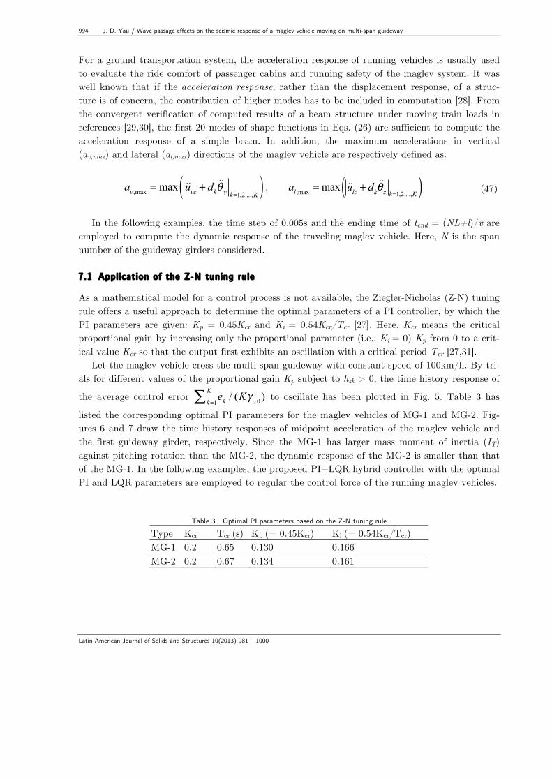
As a mathematical model for a control process is not available, the Ziegler-Nicholas (Z-N) tuning rule offers a useful approach to determine the optimal parameters of a PI controller, by which the PI parameters are given: Kp = 0.45Kcr and Ki = 0.54Kcr/Tcr [27]. Here, Kcr means the critical proportional gain by increasing only the proportional parameter (i.e., Ki = 0) Kp from 0 to a crit-ical value Kcr so that the output first exhibits an oscillation with a critical period Tcr [27,31].
Let the maglev vehicle cross the multi-span guideway with constant speed of 100km/h. By tri-als for different values of the proportional gain Kp subject to hzk > 0, the time history response of
the average control error ekk=1
K∑ / (Kγ z0 ) to oscillate has been plotted in Fig. 5. Table 3 has
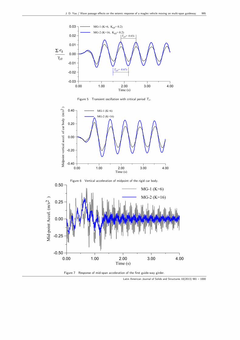
listed the corresponding optimal PI parameters for the maglev vehicles of MG-1 and MG-2. Fig-ures 6 and 7 draw the time history responses of midpoint acceleration of the maglev vehicle and the first guideway girder, respectively. Since the MG-1 has larger mass moment of inertia (IT) against pitching rotation than the MG-2, the dynamic response of the MG-2 is smaller than that of the MG-1. In the following examples, the proposed PI+LQR hybrid controller with the optimal PI and LQR parameters are employed to regular the control force of the running maglev vehicles.
Table 3 Optimal PI parameters based on the Z-N tuning rule Type Kcr Tcr (s) Kp (= 0.45Kcr) Ki (= 0.54Kcr/Tcr) MG-1 0.2 0.65 0.130 0.166 MG-2 0.2 0.67 0.134 0.161
J. D. Yau / Wave passage effects on the seismic response of a maglev vehicle moving on multi-span guideway 995
Latin American Journal of Solids and Structures 10(2013) 981 – 1000
Figure 5 Transient oscillation with critical period Tcr.
Figure 6 Vertical acceleration of midpoint of the rigid car body.
Figure 7 Response of mid-span acceleration of the first guide-way girder.
0.00 1.00 2.00 3.00 4.00Time (s)
-0.03
-0.02
-0.01
0.00
0.01
0.02
0.03
Σ ek ____ γz0
MG-1 (K=6, Kcr= 0.2)
MG-2 (K=16, Kcr= 0.2)Tcr= 0.65s
Tcr= 0.67s
0.00 1.00 2.00 3.00 4.00Time (s)
-0.40
-0.20
0.00
0.20
0.40
Mid
poin
t ver
tical
acc
el. o
f car
bod
y (m
/s2
)
MG-1 (K=6)
MG-2 (K=16)
0.00 1.00 2.00 3.00 4.00Time (s)
-0.50
-0.25
0.00
0.25
0.50
Mid
-poi
nt A
ccel
. (m
/s2
)
MG-1 (K=6)
MG-2 (K=16)
996 J. D. Yau / Wave passage effects on the seismic response of a maglev vehicle moving on multi-span guideway
Latin American Journal of Solids and Structures 10(2013) 981 – 1000
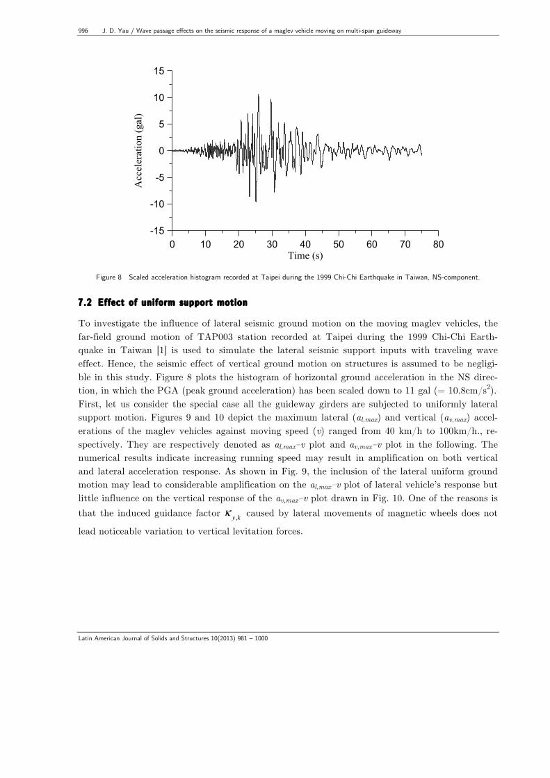
Figure 8 Scaled acceleration histogram recorded at Taipei during the 1999 Chi-Chi Earthquake in Taiwan, NS-component. 7.2 Effect of uniform support motion
To investigate the influence of lateral seismic ground motion on the moving maglev vehicles, the far-field ground motion of TAP003 station recorded at Taipei during the 1999 Chi-Chi Earth-quake in Taiwan [1] is used to simulate the lateral seismic support inputs with traveling wave effect. Hence, the seismic effect of vertical ground motion on structures is assumed to be negligi-ble in this study. Figure 8 plots the histogram of horizontal ground acceleration in the NS direc-tion, in which the PGA (peak ground acceleration) has been scaled down to 11 gal (= 10.8cm/s2). First, let us consider the special case all the guideway girders are subjected to uniformly lateral support motion. Figures 9 and 10 depict the maximum lateral (al,max) and vertical (av,max) accel-erations of the maglev vehicles against moving speed (v) ranged from 40 km/h to 100km/h., re-spectively. They are respectively denoted as al,max–v plot and av,max–v plot in the following. The numerical results indicate increasing running speed may result in amplification on both vertical and lateral acceleration response. As shown in Fig. 9, the inclusion of the lateral uniform ground motion may lead to considerable amplification on the al,max–v plot of lateral vehicle’s response but little influence on the vertical response of the av,max–v plot drawn in Fig. 10. One of the reasons is that the induced guidance factor κ y ,k caused by lateral movements of magnetic wheels does not
lead noticeable variation to vertical levitation forces.
0 10 20 30 40 50 60 70 80Time (s)
-15
-10
-5
0
5
10
15
Acc
eler
atio
n (g
al)
J. D. Yau / Wave passage effects on the seismic response of a maglev vehicle moving on multi-span guideway 997
Latin American Journal of Solids and Structures 10(2013) 981 – 1000
Figure 9 al,max-v plot of the maglev vehicle.
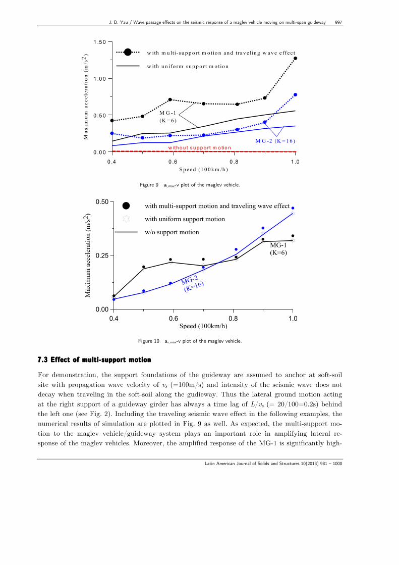
Figure 10 av,max-v plot of the maglev vehicle. 7.3 Effect of multi-support motion
For demonstration, the support foundations of the guideway are assumed to anchor at soft-soil site with propagation wave velocity of vs (=100m/s) and intensity of the seismic wave does not decay when traveling in the soft-soil along the gudieway. Thus the lateral ground motion acting at the right support of a guideway girder has always a time lag of L/vs (= 20/100=0.2s) behind the left one (see Fig. 2). Including the traveling seismic wave effect in the following examples, the numerical results of simulation are plotted in Fig. 9 as well. As expected, the multi-support mo-tion to the maglev vehicle/guideway system plays an important role in amplifying lateral re-sponse of the maglev vehicles. Moreover, the amplified response of the MG-1 is significantly high-
0 .4 0 .6 0 .8 1 .0S p ee d (1 0 0 k m /h )
0 .0 0
0 .5 0
1 .0 0
1 .5 0
Max
imum
acc
eler
atio
n (
m/s
2) w ith m u lti-su p p o rt m o tio n an d tra v e lin g w a v e e ffec t
w ith u n ifo rm su p p o rt m o tio n
M G -1(K = 6 )
M G -2 (K = 1 6 )w ith o u t s u p p o rt m o tio n
0.4 0.6 0.8 1.0Speed (100km/h)
0.00
0.25
0.50
Max
imum
acc
eler
atio
n (m
/s2 )
with multi-support motion and traveling wave effect
with uniform support motion
w/o support motion
MG-2
(K=16)
MG-1(K=6)
998 J. D. Yau / Wave passage effects on the seismic response of a maglev vehicle moving on multi-span guideway
Latin American Journal of Solids and Structures 10(2013) 981 – 1000
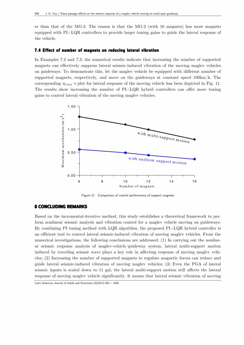
er than that of the MG-2. The reason is that the MG-2 (with 16 magnets) has more magnets equipped with PI+LQR controllers to provide larger tuning gains to guide the lateral response of the vehicle. 7.4 Effect of number of magnets on reducing lateral vibration
In Examples 7.2 and 7.3, the numerical results indicate that increasing the number of supported magnets can effectively suppress lateral seismic-induced vibration of the moving maglev vehicles on guideways. To demonstrate this, let the maglev vehicle be equipped with different number of supported magnets, respectively, and move on the guideways at constant speed 100km/h. The corresponding al,max–v plot for lateral response of the moving vehicle has been depicted in Fig. 11. The results show increasing the number of PI+LQR hybrid controllers can offer more tuning gains to control lateral vibration of the moving maglev vehicles.
Figure 11 Comparison of control performance of support magnets 8 CONCLUDING REMARKS
Based on the incremental-iterative method, this study establishes a theoretical framework to per-form nonlinear seismic analysis and vibration control for a maglev vehicle moving on guideways. By combining PI tuning method with LQR algorithm, the proposed PI+LQR hybrid controller is an efficient tool to control lateral seismic-induced vibration of moving maglev vehicles. From the numerical investigations, the following conclusions are addressed: (1) In carrying out the nonline-ar seismic response analysis of maglev-vehicle/guideway system, lateral multi-support motion induced by traveling seismic wave plays a key role in affecting response of moving maglev vehi-cles; (2) Increasing the number of supported magnets to regulate magnetic forces can reduce and guide lateral seismic-induced vibration of moving maglev vehicles; (3) Even the PGA of lateral seismic inputs is scaled down to 11 gal, the lateral multi-support motion still affects the lateral response of moving maglev vehicle significantly. It means that lateral seismic vibration of moving
6 8 10 12 14 16N u m b er o f m ag n e ts
0 .0 0
0 .5 0
1 .0 0
1 .5 0
Max
imum
acc
eler
atio
n (m
/s2 )
w ith m u lti-su p p o rt m o tio n
w ith u n ifo rm su p p o rt m o tio n
J. D. Yau / Wave passage effects on the seismic response of a maglev vehicle moving on multi-span guideway 999
Latin American Journal of Solids and Structures 10(2013) 981 – 1000
maglev vehicle may dominate dynamic interaction behaviors of maglev transport. Acknowledgements This research was partially supported by the National Science Council in Taiwan through the Grants: NSC 99-2221-E-032-020-MY3. The author would like to express his gratitude for this financial support by the National Natural Science Foundation of China (Grant No. 10972196) when he visited Zhejiang University for academic research of 2012. References
[1] Y.B. Yang J.D. Yau and Y.S. Wu, Vehicle-Bridge Interaction Dynamics. Singapore, World Scientific, 2004. [2] Y.B. Yang and H.H Hung, Wave propagation for train-induced vibrations – a finite/infinite element ap-
proach. Singapore, World Scientific, 2009. [3] G. Samavedam, S. Kokkins, F. Raposa, M. Thompson, and G. Anagnostopoulos, Assessment of CHSST
Maglev for U.S. Urban Transportation, U.S. Department of Transportation, Federal Transit Administration, Report Number FTA-MD-26-7029-2002.1. 2002.
[4] J. Shi, Q. Wei, and Y. Zhao, Analysis of dynamic response of the high-speed EMS maglev vehicle/guideway coupling system with random irregularity, Veh. Sys. Dyn., 45:1077-1095, 2007.
[5] J. Shi and Y.J. Wang. Dynamic response analysis of single-span guideway caused by high speed maglev train, Latin American Journal of Solids and Structures, 8:213-228, 2011.
[6] D.H. Shi, Maglev rail technology in Japan and its potential applications, Journal of Transportation Systems Engineering and Information Technology, 7(5):1–4, 2007.
[7] S.D. Kwon, J.S., Lee, J. W. Moon, and M. Y. Kim, Dynamic interaction analysis of urban transit maglev vehicle and guideway suspension bridge subjected to gusty wind, Eng. Struct., 30:3445-3456, 2008.
[8] A. Bittar and R.M. Sales, H2 and H∞ control for maglev vehicles, IEEE Control Sys. Mag. 18(4):18-25,
1998. [9] G. Bohn and G. Steinmetz, The electromagnetic levitation and guidance technology of the Transrapid test
facility Emsland, IEEE Trans. Mag., 20(5):1666-1671, 1984. [10] Y. Cai, S.S. Chen, D.M. Rote, and H.T. Coffey, Vehicle/guideway dynamic interaction in maglev systems, J.
Dyn. Sys. Meas. Cont., 118:526–530, 1996. [11] Y. Cai and S.S. Chen, Dynamic characteristics of magnetically-levitated vehicle systems, A Mech. Rev.,
50(11):647–670, 1997. [12] X.J. Zheng, J.J. Wu, and Y.H. Zhou, Numerical analyses on dynamic control of five-degree-of-freedom mag-
lev vehicle moving on flexible guideways, J. Sound Vib., 235:43–61, 1997. [13] X.J. Zheng, J.J. Wu, and Y.H. Zhou, Effect of spring non-linearity on dynamic stability of a controlled mag-
lev vehicle and its guideway system, J. Sound Vib., 279:201–215, 2005. [14] C.F. Zhao and W.M. Zhai, Maglev vehicle/guideway vertical random response and ride quality, Veh. Sys.
Dyn., 38(3):185–210, 2002. [15] J.D. Yau, Vibration control of maglev vehicles traveling over a flexible guideway, J. Sound Vib., 321:184–
200, 2009. [16] J.D. Yau, Response of a maglev vehicle moving on a series of guideways with differential settlement, J.
Sound Vib., 324:816-831, 2009. [17] J.D. Yau, Interaction response of maglev masses moving on a suspended beam shaken by horizontal ground
motion, J. Sound Vib., 329:171-188, 2010. [18] J.D. Yau, Response of a maglev vehicle moving on a two-span flexible guideway, J. Mech., 26(1):95-103,
2010. [19] J.D. Yau, Aerodynamic vibrations of a maglev vehicle running on flexible guideways under oncoming wind
actions, J. Sound Vib., 329:1743-1759, 2010. [20] Y.B. Yang and J.D. Yau, An iterative interacting method for dynamic analysis of the maglev train–
guideway/foundation–soil system, Eng. Struct., 33:1013-1024, 2011.
1000 J. D. Yau / Wave passage effects on the seismic response of a maglev vehicle moving on multi-span guideway
Latin American Journal of Solids and Structures 10(2013) 981 – 1000
[21] J.D. Yau. Lateral vibration control of a low-speed maglev vehicle in cross winds, Wind and Structures, 15(3):263-283, 2012.
[22] P. Leger, I. M. Ide, and P. Paultre, Multiple-support seismic analysis of large structures, Computers & Structures, 36(6):1153-1158, 1990.
[23] H. Xia, Y. Han, N. Zhang, W. Guo, Dynamic analysis of train–bridge system subjected to non-uniform seis-mic excitations, Earthq. Eng. & Struct. Dyna., 35(12):1563–1579, 2006.
[24] D. Aldo and R. Alfred, Design of an integrated electromagnetic levitation and guidance system for Swiss Metro, EPE'99, Lausanne, Swiss, 1999.
[25] T.T. Soong, Active structural control: theory and practice, Longman Scientific & Technical, Essex, England, 1990.
[26] K.J. Astrom and T. Hagglund, Automatic Tuning of PID Controllers, Instrument Society of America, USA, 1988.
[27] K. Ogata, Modern Control Engineering, 3rd ed, Prentice-Hall, Englewood Cliffs, N.J., 1997. [28] J.D. Yau, Vehicle/bridge interactions of a rail suspension bridge considering support movements, Interaction
and Multistage Mechanics: an International Journal, 2(3):263-276, 2009. [29] J.D. Yau and Y. B. Yang, Vertical accelerations of simple beams due to successive loads traveling at reso-
nant speeds, J. Sound Vib., 289:210-228, 2006. [30] Y.J. Wang, Q.C. Wei, J. Shi, and X.Y. Long. Resonance characteristics of two-span continuous beam under
moving high speed trains. Latin American Journal of Solids and Structures, 7(2):185–199, 2010. [31] J.D. Yau, Lateral vibration control of a low-speed maglev vehicle in cross winds. Wind and Structures,
15(3):263-283, 2012.