Embed Size (px)
Citation preview
Tennessee Valley Authority, Post Office Box 2000, Spring City, Tennessee 37381-2000
Richard T. Purcell Site Vice President, Watts Bar Nuclear Plant
S}i
U. S. Nuclear Regulatory Commission ATTN: Document Control Desk Washington, D.C. 20555
Gentlemen:
In the Matter of ) Docket No. 50-390 Tennessee Valley Authority
WATTS BAR NUCLEAR PLANT (WBN) UNIT 1 - CLARIFICATION OF "RESPONSE TIME TEST (RTT) ELIMINATION" TECHNICAL SPECIFICATION (TS) CHANGE NO. 99-007
Reference: TVA LETTER TO NRC DATED SEPTEMBER 28, 1999, "WATTS BAR NUCLEAR PLANT (WBN) UNIT 1 - TECHNICAL SPECIFICATION (TS) CHANGE NO. 99-007, 'RESPONSE TIME TEST (RTT) ELIMINATION'"
This letter documents NRC questions on the referenced letter and provides TVA's response to the questions. On January 5, 2000, a telephone conference was conducted between NRC and TVA to discuss TVA's proposed TS changes for WEN (provided in the referenced letter) and Sequoyah Nuclear Plant (SQN) (provided in TVA's letter dated August 30, 1999), concerning elimination of response time testing. A followup conference call was held on January 27, 2000. From the conference calls, it was determined that clarification of some areas of the WBN and SQN submittals was needed in order to complete the staff's evaluation of the proposed changes.
The SQN response to the NRC Staff questions was provided in TVA's letter to the NRC dated January 13, 2000, "Sequoyah Nuclear Plant Units 1 and 2 - Clarification of Response Time Test Elimination TS Change No. 99-08." The NRC reviewed the additional information provided by SQN and issued an approved license amendment and safety evaluation for SQN TS-99-08 on February 29, 2000. Enclosure 1 to this letter provides the response to the conference call questions for the referenced WBN application (TS-99-007). Enclosure 2 contains applicable commitments.
Pnnted on recycle paper 'D Cý5 C
U.S. Nuclear Regulatory Commission Page 2
MAR 1 7 2000
If you have any questions about this response, please telephone Paul L. Pace at (423) 365-1824.
Sincerely,
Enclosures cc (Enclosures)
NRC Resident Inspector Watts Bar Nuclear Plant 1260 Nuclear Plant Road Spring City, Tennessee 37381
Mr. Robert E. Martin, Senior Project Manager U.S. Nuclear Regulatory Commission One White Flint North 11555 Rockville Pike Rockville, Maryland 20852
U.S. Nuclear Regulatory Commission Region II Atlanta Federal Center 61 Forsyth St., SW, Suite 23T85 Atlanta, Georgia 30303
Mr. Michael H. Mobley, Director Division of Radiological Health 3 rd Floor
L & C Annex Nashville, Tennessee 37423
ENCLOSURE 1
TENNESSEE VALLEY AUTHORITY WATTS BAR NUCLEAR PLANT (WBN)
UNIT 1- DOCKET NO. 390
CLARIFICATION OF RESPONSE TIME TEST (RTT) ELIMINATION TECHNICAL SPECIFICATION (TS) CHANGE NO. 99-007
NRC QUESTION NO. 1:
Condition 2:
The licensee's response does not address switches. The licensee is requested to address its plans for RTT for switches in response to the condition in the SE. Also, please clarify the meaning of the term "that can be tested" with respect to whether its interpretation would exclude any transmitters or switches that use capillary tubes from the testing addressed by the SE condition.
WBN RESPONSE NO. 1:
Switches were intentionally omitted from the original TS change request because there are no switches with capillary tubes in the WBN RTT Program. Additionally, WBN does not employ transmitters or switches with capillary sensing lines in applications that require response time testing.
The term " . . . that can be tested . . " was added to provide
flexibility in the event that a future design condition may need the exclusion. However, since future changes to response time test exclusions require NRC approval, the term is not needed and should be removed. Additionally, since these applications do not exist at WBN, implementation of this condition is not applicable.
WBN has revised Commitment No. 2 of TVA's September 28, 1999 letter to read as follows:
Plant procedure revisions (and/or other appropriate administrative controls) will stipulate that pressure sensors (transmitters and switches) utilizing capillary tubes must be subjected to response time testing after initial installation and following any maintenance or modification activity that could damage the transmitter capillary tubes.
EI-I
NRC QUESTION NO. 2:
Condi ti on 3:
The licensee's response adequately addresses the present plant condition. However the licensee is requested to address its plans and commitments for addressing RTT issues if future actions result in the replacement of transmitters with those having variable damping capability.
WBN RESPONSE NO. 2:
A commitment will be added to the WBN Commitment Tracking System before implementation of the approved TS change that states:
The applicable plant procedures (or appropriate administrative controls) will stipulate that pressure transmitters equipped with variable damping capability in reactor trip system or engineered safety features response time applications, which require periodic response time test, must be subjected to response time testing after initial installation or following any maintenance or modification activity. Administrative controls may include use of pressure transmitters that are factory set and hermetically sealed to prohibit tampering or in situ application of a tamper seal (or sealant) on the potentiometer to secure and give visual indication of the potentiometer position.
NRC QUESTION NO. 3:
Item - Allocated sensor response times
The staff's SE for WCAP-13632 notes that Westinghouse has proposed using allocated sensor response times in accordance with the methodology described in Section 9 of WCAP-13632, Revision 2. Allocations for sensor response times would be obtained from (1) historical records based on acceptable RTT (hydraulic, noise, or power interrupt tests), (2) inplace, onsite, or offsite (e.g., vendor) test measurements, or (3) utilizing vendor engineering specifications. In this regard, Tables 1 and 2 of WBN's application identifies RTS and ESFAS equipment and provides the bounding response time values to be used for WBN equipment. Note 1 indicates that allocated response times for the Foxboro transmitters are supported by actual tests of the transmitters installed at WBN, e.g., method (1) above. NRC requests that TVA provide this data to the staff and provide a statistical basis for the selection of the allocated response times for the Foxboro transmitters.
E1-2
WBN RESPONSE NO. 3:
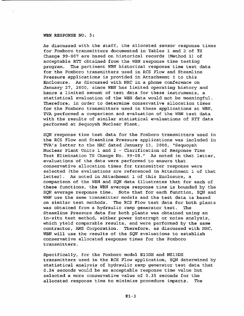
As discussed with the staff, the allocated sensor response times for Foxboro transmitters documented in Tables 1 and 2 of TS Change 99-007 are based on historical records (Method 1) of acceptable RTT obtained from the WBN response time testing program. The pertinent WEN historical response time test data for the Foxboro transmitters used in RCS Flow and Steamline Pressure applications is provided in Attachment 1 to this Enclosure. As discussed with NRC in a phone conference on January 27, 2000, since WBN has limited operating history and hence a limited amount of test data for these instruments, a statistical evaluation of the WBN data would not be meaningful. Therefore, in order to determine conservative allocation times for the Foxboro transmitters used in these applications at WBN, TVA performed a comparison and evaluation of the WBN test data with the results of similar statistical evaluations of RTT data performed at Sequoyah Nuclear Plant.
SQN response time test data for the Foxboro transmitters used in the RCS Flow and Steamline Pressure applications was included in TVA's letter to the NRC dated January 13, 2000, "Sequoyah Nuclear Plant Units 1 and 2 - Clarification of Response Time Test Elimination TS Change No. 99-08." As noted in that letter, evaluations of the data were performed to ensure that conservative allocation times for transmitter response were selected (the evaluations are referenced in Attachment 1 of that letter). As noted in Attachment 1 of this Enclosure, a comparison of the WBN and SQN data illustrates that for each of these functions, the WBN average response time is bounded by the SQN average response time. Note that for each function, SQN and WBN use the same transmitter models and the test data is based on similar test methods. The RCS Flow test data for both plants was obtained from a hydraulic ramp generator test. The Steamline Pressure data for both plants was obtained using an in-situ test method, either power interrupt or noise analysis, which yield comparable results, and were performed by the same contractor, AMS Corporation. Therefore, as discussed with NRC, WBN will use the results of the SQN evaluations to establish conservative allocated response times for the Foxboro transmitters.
Specifically, for the Foxboro model E13DH and NE13DH transmitters used in the RCS Flow application, SQN determined by statistical analysis of hydraulic ramp generator test data that 0.24 seconds would be an acceptable response time value but selected a more conservative value of 0.35 seconds for the allocated response time to minimize procedure impacts. The
E1-3
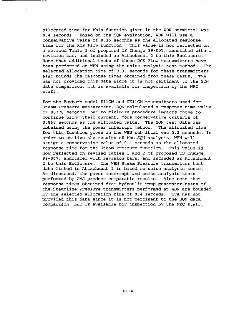
allocated time for this function given in the WBN submittal was 0.4 seconds. Based on the SQN evaluation, WBN will use a conservative value of 0.35 seconds as the allocated response time for the RCS Flow function. This value is now reflected on a revised Table 1 of proposed TS Change 99-007, annotated with a revision bar, and included as Attachment 2 to this Enclosure. Note that additional tests of these RCS Flow transmitters have been performed at WBN using the noise analysis test method. The selected allocation time of 0.35 seconds for these transmitters also bounds the response times obtained from these tests. TVA has not provided this data since it is not pertinent to the SQN data comparison, but is available for inspection by the NRC staff.
For the Foxboro model E11GM and NE11GM transmitters used for Steam Pressure measurement, SQN calculated a response time value of 0.378 seconds, but to minimize procedure impacts chose to continue using their current, more conservative criteria of 0.867 seconds as the allocated value. The SQN test data was obtained using the power interrupt method. The allocated time for this function given in the WBN submittal was 0.2 seconds. In order to utilize the results of the SQN analysis, WBN will assign a conservative value of 0.4 seconds as the allocated response time for the Steam Pressure function. This value is now reflected on revised Tables 1 and 2 of proposed TS Change 99-007, annotated with revision bars, and included as Attachment 2 to this Enclosure. The WBN Steam Pressure transmitter test data listed in Attachment 1 is based on noise analysis tests. As discussed, the power interrupt and noise analysis tests performed by AMS produce comparable results. Also note that response times obtained from hydraulic ramp generator tests of the Steamline Pressure transmitters performed at WEN are bounded by the selected allocation time of 0.4 seconds. TVA has not provided this data since it is not pertinent to the SQN data comparison, but is available for inspection by the NRC staff.
El-4

ATTACHMENT 1
WBN RESPONSE TIME TEST DATA FOR FOXBORO TRANSMITTERS
Steamline Pressure Transmitters Response Time Test Data (Sept. 1996 - Feb. 1999)
Model E11GM / NE11GMTransmitter Response Date ID Time
(sec)
1-PT-1-2A 0.09 9/96
1-PT-1-2B 0.17 1/98 1-PT-1-5 0.12 2/99
1-PT-1-27A 0.09 9/96 1-PT-1-27B 0.09 1/98 1-PT-1-30 0.28 2/99
RCS Flow Transmitters Response Time Test Data
(May 1995), Model E13DH / NE13DH
Transmitter Response Time ID (sec)
1-FT-68-6A 0.105 1-FT-68-6B 0.125 1-FT-68-6D 0.1625
1-FT-68-29A 0.120 1-FT-68-29B 0.125
1-FT-68-29D 0.085
1-FT-68-48A 0.100
1-FT-68-48B 0.170
1-FT-68-48D 0.100
1-FT-68-71A 0.105 1-FT-68-71B 0.123
1-FT-68-71D 0.1175
WBEN SQN
Min 0.085 0.05 Max 0.170 0.24 Average 0.120 0.135
* Statistical outlier but retained in analysis for conservatism
(1) SQN data provided in TVA letter to NRC dated January 13, 2000.
El-5
[WBN JSQN (1)
Min 0.09 0.14 Max 0.28 0.63 *
Average 0.140 0.192
ATTACHMENT 2
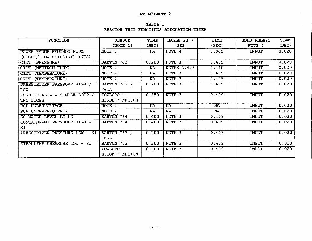
TABLE 1 REACTOR TRIP FUNCTIONS ALLOCATION TIMES
EI-6
FUNCTION SENSOR TIME EAGLE 21 / TIME SSPS RELAYS TIME (NOTE 1) (SEC) NIS (SEC) (NOTE 6) (SEC)
POWER RANGE NEUTRON FLUX NOTE 2 NA NOTE 4 0.065 INPUT 0.020
(HIGH / LOW SETPOINT) (NIS)
OTDT (PRESSURE) BARTON 763 0.200 NOTE 3 0.409 INPUT 0.020
OTDT (NEUTRON FLUX) NOTE 2 NA NOTES 3,4,5 0.410 INPUT 0.020
OTDT (TEMPERATURE) NOTE 2 NA NOTE 3 0.409 INPUT 0.020
OPDT (TEMPERATURE) NOTE 2 NA NOTE 3 0.409 INPUT 0.020
PRESSURIZER PRESSURE HIGH / BARTON 763 / 0.200 NOTE 3 0.409 INPUT 0.020
LOW 763A LOSS OF FLOW - SINGLE LOOP / FOXBORO 0.350 NOTE 3 0.409 INPUT 0.020
TWO LOOPS E13DH / NE13DH
RCP UNDERVOLTAGE NOTE 2 NA NA NA INPUT 0.020
RCP UNDERFREQUENCY NOTE 2 NA NA NA INPUT 0.020
SG WATER LEVEL LO-LO BARTON 764 0.400 NOTE 3 0.409 INPUT 0.020
CONTAINMENT PRESSURE HIGH - BARTON 764 0.400 NOTE 3 0.409 INPUT 0.020
SI
PRESSURIZER PRESSURE LOW - SI BARTON 763 / 0.200 NOTE 3 0.409 INPUT 0.020 763A
STEAMLINE PRESSURE LOW - SI BARTON 763 0.200 NOTE 3 0.409 INPUT 0.020
FOXBORO 0.400 NOTE 3 0.409 INPUT 0.020 E11GM / NE11GM
ATTACHMENT 2
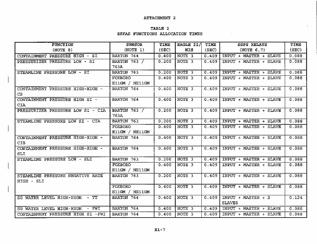
TABLE 2 ESFAS FUNCTIONS ALLOCATION TIMES
FUNCTION SENSOR TIME EAGLE 21/ TIME SSPS RELAYS TIME (NOTE 8) (NOTE 1) (SEC) NIS (SEC) (NOTE 6,7) (SEC)
CONTAINMENT PRESSURE HIGH - SI BARTON 764 0.400 NOTE 3 0.409 INPUT + MASTER + SLAVE 0.088
PRESSURIZER PRESSURE LOW SI BARTON 763 / 0.200 NOTE 3 0.409 INPUT + MASTER + SLAVE 0.088 763A
STEAMLINE PRESSURE LOW - SI BARTON 763 0.200 NOTE 3 0.409 INPUT + MASTER + SLAVE 0.088 FOXBORO 0.400 NOTE 3 0.409 INPUT + MASTER + SLAVE 0.088
E11GM / NE11GM
CONTAINMENT PRESSURE HIGH-HIGH - BARTON 764 0.400 NOTE 3 0.409 INPUT + MASTER + SLAVE 0.088 CS I
CONTAINMENT PRESSURE HIGH SI - BARTON 764 0.400 NOTE 3 0.409 INPUT + MASTER + SLAVE 0.088 CIA PRESSURIZER PRESSURE LOW SI - CIA BARTON 763 / 0.200 NOTE 3 0.409 INPUT + MASTER + SLAVE 0.088
763A
STEAMLINE PRESSURE LOW SI - CIA BARTON 763 0.200 NOTE 3 0.409 INPUT + MASTER + SLAVE 0.088 FOXBORO 0.400 NOTE 3 0.409 INPUT + MASTER + SLAVE 0.088 E11GM / NE11GM
CONTAINMENT PRESSURE HIGH-HIGH - BARTON 764 0.400 NOTE 3 0.409 INPUT + MASTER + SLAVE 0.088 CIB
CONTAINMENT PRESSURE HIGH-HIGH - BARTON 764 0.400 NOTE 3 0.409 INPUT + MASTER + SLAVE 0.088 SLI
STEAMLINE PRESSURE LOW - SLI BARTON 763 0.200 NOTE 3 0.409 INPUT + MASTER + SLAVE 0.088 FOXBORO 0.400 NOTE 3 0.409 INPUT + MASTER + SLAVE 0.088 E11GM / NE11GM
STEAMLINE PRESSURE NEGATIVE RATE BARTON 763 0.200 NOTE 3 0.409 INPUT + MASTER + SLAVE 0.088 HIGH - SLI
FOXBORO 0.400 NOTE 3 0.409 INPUT + MASTER + SLAVE 0.088 E11GM / NE11GM
SG WATER LEVEL HIGH-HIGH - TT BARTON 764 0.400 NOTE 3 0.409 INPUT + MASTER + 2 0.124 SLAVES
SG WATER LEVEL HIGH-HIGH - FWI BARTON 764 0.400 NOTE 3 0.409 INPUT + MASTER + SLAVE 0.088
CONTAINMENT PRESSURE HIGH SI -FWI BARTON 764 0.400 NOTE 3 0.409 INPUT + MASTER + SLAVE 0.088
El-7
ATTACHMENT 2
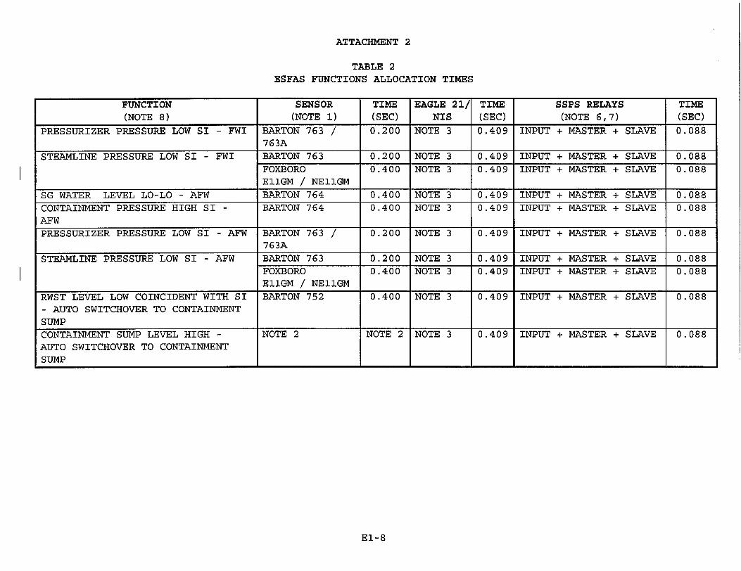
TABLE 2 ESFAS FUNCTIONS ALLOCATION TIMES
EI-8
FUNCTION SENSOR TIME EAGLE 21/ TIME SSPS RELAYS TIME
(NOTE 8) (NOTE 1) (SEC) NIS (SEC) (NOTE 6,7) (SEC)
PRESSURIZER PRESSURE LOW SI - FWI BARTON 763 / 0.200 NOTE 3 0.409 INPUT + MASTER + SLAVE 0.088 763A
STEAMLINE PRESSURE LOW SI - FWI BARTON 763 0.200 NOTE 3 0.409 INPUT + MASTER + SLAVE 0.088 FOXBORO 0.400 NOTE 3 0.409 INPUT + MASTER + SLAVE 0.088 EI1GM / NE11GM
SG WATER LEVEL LO-LO - AFW BARTON 764 0.400 NOTE 3 0.409 INPUT + MASTER + SLAVE 0.088
CONTAINMENT PRESSURE HIGH SI - BARTON 764 0.400 NOTE 3 0.409 INPUT + MASTER + SLAVE 0.088 AFW
PRESSURIZER PRESSURE LOW SI - AFW BARTON 763 / 0.200 NOTE 3 0.409 INPUT + MASTER + SLAVE 0.088 76 3A
STEAMLINE PRESSURE LOW SI - AFW BARTON 763 0.200 NOTE 3 0.409 INPUT + MASTER + SLAVE 0.088 FOXBORO 0.400 NOTE 3 0.409 INPUT + MASTER + SLAVE 0.088 E11GM / NE11GM
RWST LEVEL LOW COINCIDENT WITH SI BARTON 752 0.400 NOTE 3 0.409 INPUT + MASTER + SLAVE 0.088 - AUTO SWITCHOVER TO CONTAINMENT SUMP
CONTAINMENT SUMP LEVEL HIGH - NOTE 2 NOTE 2 NOTE 3 0.409 INPUT + MASTER + SLAVE 0.088 AUTO SWITCHOVER TO CONTAINMENT SUMP
ATTACHMENT 2
TABLES 1 & 2 NOTES RTS/ESFAS FUNCTIONS ALLOCATION TIMES
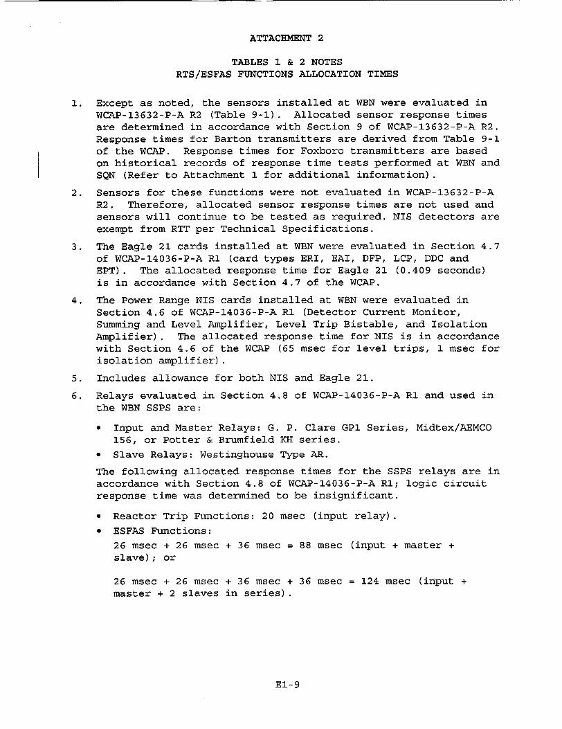
1. Except as noted, the sensors installed at WEN were evaluated in WCAP-13632-P-A R2 (Table 9-1). Allocated sensor response times are determined in accordance with Section 9 of WCAP-13632-P-A R2. Response times for Barton transmitters are derived from Table 9-1 of the WCAP. Response times for Foxboro transmitters are based on historical records of response time tests performed at WBN and SQN (Refer to Attachment 1 for additional information).
2. Sensors for these functions were not evaluated in WCAP-13632-P-A R2. Therefore, allocated sensor response times are not used and sensors will continue to be tested as required. NIS detectors are exempt from RTT per Technical Specifications.
3. The Eagle 21 cards installed at WBN were evaluated in Section 4.7 of WCAP-14036-P-A R1 (card types ERI, EAI, DFP, LCP, DDC and EPT). The allocated response time for Eagle 21 (0.409 seconds) is in accordance with Section 4.7 of the WCAP.
4. The Power Range NIS cards installed at WBN were evaluated in Section 4.6 of WCAP-14036-P-A RI (Detector Current Monitor, Summing and Level Amplifier, Level Trip Bistable, and Isolation Amplifier). The allocated response time for NIS is in accordance with Section 4.6 of the WCAP (65 msec for level trips, 1 msec for isolation amplifier).
5. Includes allowance for both NIS and Eagle 21.
6. Relays evaluated in Section 4.8 of WCAP-14036-P-A R1 and used in the WBN SSPS are:
"* Input and Master Relays: G. P. Clare GPl Series, Midtex/AEMCO 156, or Potter & Brumfield KH series.
"* Slave Relays: Westinghouse Type AR.
The following allocated response times for the SSPS relays are in accordance with Section 4.8 of WCAP-14036-P-A R1; logic circuit response time was determined to be insignificant.
* Reactor Trip Functions: 20 msec (input relay).
* ESFAS Functions:
26 msec + 26 msec + 36 msec = 88 msec (input + master + slave); or
26 msec + 26 msec + 36 msec + 36 msec = 124 msec (input + master + 2 slaves in series).
E1-9
ATTACHMENT 2
TABLES 1 & 2 NOTES RTS/ESFAS FUNCTIONS ALLOCATION TIMES
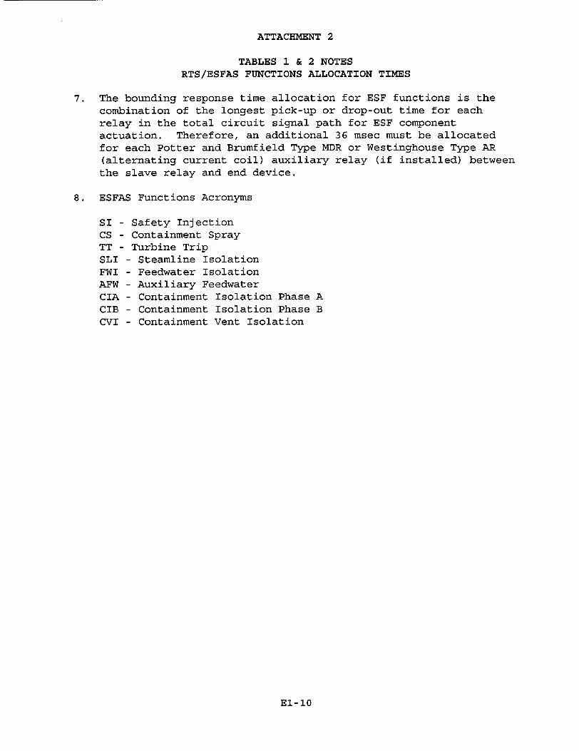
7. The bounding response time allocation for ESF functions is the combination of the longest pick-up or drop-out time for each relay in the total circuit signal path for ESF component actuation. Therefore, an additional 36 msec must be allocated for each Potter and Brumfield Type MDR or Westinghouse Type AR (alternating current coil) auxiliary relay (if installed) between the slave relay and end device.
8. ESFAS Functions Acronyms
SI - Safety Injection CS - Containment Spray TT - Turbine Trip SLI - Steamline Isolation FWI - Feedwater Isolation AFW - Auxiliary Feedwater CIA - Containment Isolation Phase A CIB - Containment Isolation Phase B CVI - Containment Vent Isolation
El-10
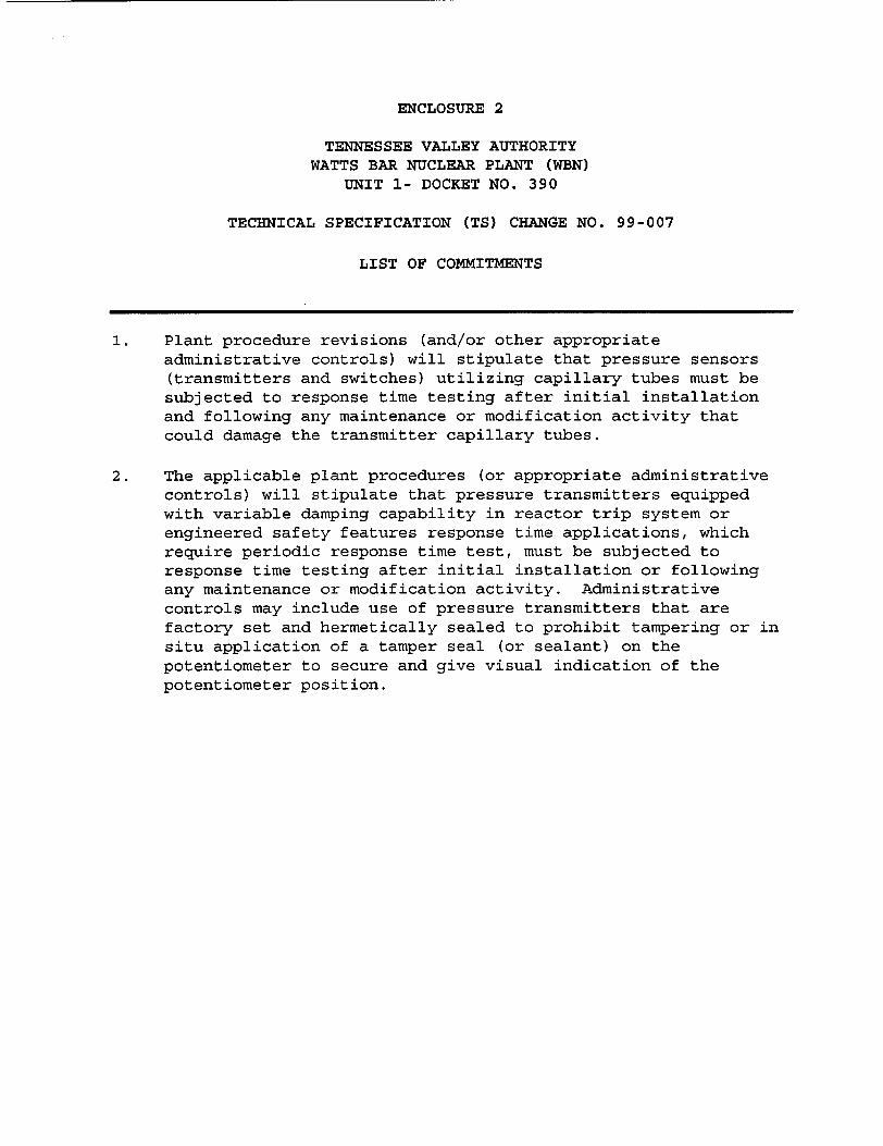
ENCLOSURE 2
TENNESSEE VALLEY AUTHORITY WATTS BAR NUCLEAR PLANT (WBN)
UNIT 1- DOCKET NO. 390
TECHNICAL SPECIFICATION (TS) CHANGE NO. 99-007
LIST OF COMMITMENTS
1. Plant procedure revisions (and/or other appropriate administrative controls) will stipulate that pressure sensors (transmitters and switches) utilizing capillary tubes must be subjected to response time testing after initial installation and following any maintenance or modification activity that could damage the transmitter capillary tubes.
2. The applicable plant procedures (or appropriate administrative controls) will stipulate that pressure transmitters equipped with variable damping capability in reactor trip system or engineered safety features response time applications, which require periodic response time test, must be subjected to response time testing after initial installation or following any maintenance or modification activity. Administrative controls may include use of pressure transmitters that are factory set and hermetically sealed to prohibit tampering or in situ application of a tamper seal (or sealant) on the potentiometer to secure and give visual indication of the potentiometer position.


![Rich Communication Suite 5.0 Advanced Communications ...€¦ · RCS 5.0 builds on the fundamentals from RCS Release 1 to 4 and RCS-e (RCS-enhanced) 1.2 (see [RCSe12]) that are succeeded](https://img.pdfslide.us/doc/110x75/5ed9a866186b8d62dd017224/rich-communication-suite-50-advanced-communications-rcs-50-builds-on-the-fundamentals.jpg)


![[Rcs Iot] Rcs-e v1-2- Joyn](https://img.pdfslide.us/doc/110x75/577cd0231a28ab9e78917fbc/rcs-iot-rcs-e-v1-2-joyn.jpg)