Embed Size (px)
Citation preview

29/01/2010
Waterstage 3 phase
Air/Water Heat Pump
Split System, Single Service 3 phase 112, 140 and 160
Document 1394-1 ~ 29/01/2010
Maintenance Document
Intended for
professional use
Fujitsu General (Euro) GmbH Werftstrasse 20
40549 Düsseldorf - Germany
Subject to change without notice Non contractual document
EN FR NL DE IT


29/01/2010
Contents
1 Technical Characteristics ..............................................................................................6 1.1 Specifications .................................6 1.2 Performance Data ..........................6
1.2.1 Rated Performance..........................6 1.2.2 Maximum Stated Performance ........6 1.2.3 Performance Curves for Waterstage 112................................................................7
1.2.4 Performance Curves for Waterstage 140................................................................7 1.2.5 Performance Curves for Waterstage 160................................................................8
1.3 Hydraulic Characteristics ...............8 1.4 Refrigeration Diagram....................9
2 Installation Rules..........................................................................................................10
2.1 Heat Pump ...................................10 2.1.1 Outdoor Units.................................10 2.1.2 Hydraulic Unit.................................11
2.2 Control Terminal...........................12 2.2.1 Room Unit ......................................12
2.2.2 User Interface ................................ 12 2.3 Electrical Connections .................14
2.3.1 Installation Precautions ................. 14 2.3.2 Electrical Connection Overview..... 14 2.3.3 Hydraulic Unit Connection Diagram16
3 Getting Started..............................................................................................................17
3.1 Checks .........................................17 3.1.1 Outdoor Unit...................................17 3.1.2 Hydraulic Unit.................................17 3.1.3 Hydraulic System ...........................17 3.1.4 Electrical System ...........................17 3.1.5 Refrigeration System .....................17
3.2 Settings ........................................18 3.3 Operating Modes..........................18
3.3.1 Manual Adjustment........................ 18 3.3.2 Auto Adapt Adjustment.................. 20
3.4 Control of Electric Backups..........20 3.5 Domestic Hot Water.....................20
3.5.1 Principle of Operation.................... 21 3.6 Test Mode ....................................21
3.6.1 Sensor and Input Test Mode ......... 21 3.6.2 Output Test Mode.......................... 22
4 Faults .............................................................................................................................23
4.1 Fault List.......................................23 4.1.1 Hydraulic Unit Fault........................23 4.1.2 Outdoor Unit Fault..........................25
4.2 Outdoor Unit Clearing...................26 4.2.1 Failures with Error Code ................26 4.2.2 Failures With No Error Code..........48
4.3 Sensor Values..............................52 4.3.1 Outdoor Unit Temperature Sensors.......................................................52 4.3.2 Hydraulic Unit Temperature Sensors.......................................................52
4.4 Service parts information..............53
4.4.1 Service parts information 1 : Compressor ................................................ 53 4.4.2 Service parts information 2 : Inverter compressor................................................. 54 4.4.3 Service parts information 3 : Outdoor unit electronic expansion valve (EEV, EEV(INJ))....................................................55 4.4.4 Service parts information 4 : Outdoor unit solenoid valve (SV).............................. 56
4.5 Operating Limits...........................57
5 Failures..........................................................................................................................58
5.1 Hydraulic, Electric and Refrigeration Systems ...................................................58
5.1.1 Hydraulic System ...........................58 5.1.2 Electrical System ...........................59
5.1.3 Refrigeration System..................... 60 5.2 Compressor Operating Checks....62 5.3 Refrigeration Circuit Leak Test ....62 5.4 Troubleshooting ...........................62

Heat Pump, Split System, Single Service, 3 phase
4 Maintenance Document 1394-1
6 Control Settings............................................................................................................63 6.1 General ........................................63 6.2 Function Table .............................63 6.3 Adjustment Function Details ........69
6.3.1 Date and Time Functions.............. 69 6.3.2 User Interface Functions............... 71 6.3.3 Time Program Functions (heating circuit 1 & 2, DHW, cooling).................................. 73 6.3.4 Heating Circuit 1 & 2 Functions .... 74 6.3.5 Cooling Circuit 1 Functions ........... 82 6.3.6 DHW Functions ............................. 89 6.3.7 Swimming Pool Functions............. 92
6.3.8 Heat Pump Functions ....................92 6.3.9 DHW Tank Functions ....................93 6.3.10 Configuration Functions.................95 6.3.11 Error Functions ..............................97 6.3.12 Maintenance / Special Operating Mode Functions ..................................................101 6.3.13 Input / Output Testing Functions .103 6.3.14 Status Functions..........................104 6.3.15 Generator Diagnosis Functions ...109 6.3.16 Consumer Diagnosis Functions...110
7 Annual Maintenance Services ...................................................................................113
7.1 Hydraulic Circuit.........................113 7.2 Outdoor unit ...............................113
7.3 Electrical .................................... 113 7.4 Operating checks....................... 113
8 Connection Diagrams.................................................................................................114
8.1 Connection Diagram of Hydraulic Unit..........................................................114
8.2 Connection Diagram of Outdoor Unit.........................................................115
9 Disassembly Process of Outdoor Unit......................................................................116
9.1 Appearance................................116 9.2 Service panel removal ...............116 9.3 Insulation sheet removal ............116 9.4 Main PCB removal .....................117 9.5 INVERTER, PFC, FILTER, and CAPACITOR PCB removal....................117
9.5.1 INVERTER PCB removal............ 118 9.5.2 PFC PCB removal....................... 118 9.5.3 FILTER PCB removal.................. 118 9.5.4 CAPACITOR PCB removal......... 119
9.6 FAN MOTOR removal................120 9.7 TOP PANEL removal .................120 9.8 PIPE COVER FRONT removal..120 9.9 RIGHT PANEL removal .............121 9.10 REACTOR removal....................121
9.11 THERMISTOR removal ............. 121 9.11.1 HEAT EXCHANGER (OUT) THERMISTOR..........................................121 9.11.2 EXPANSION VALVE THERMISTOR 121
9.12 SOLENOID COIL removal ......... 122 9.12.1 4WAY VALVE..............................122 9.12.2 INJECTION..................................122
9.13 EEV COIL removal .................... 122 9.13.1 MAIN............................................122 9.13.2 INJECTION..................................122
9.14 PRESSURE SENSOR removal . 122 9.15 COMPRESSOR removal ........... 123 9.16 Precautions for exchange of refrigerant-cycle-parts ........................... 125
10 Spare Parts..................................................................................................................126 11 Accessories.................................................................................................................127
11.1 DHW kit......................................127 11.2 Swimming pool kit ......................127 11.3 2nd circuit kit ..............................127 11.4 Room Sensor .............................127
11.4.1 Room thermostat......................... 127 11.4.2 Remote control............................ 129
11.5 Boiler connection kit...................130 11.6 Cooling kit ..................................130
11.7 High flow rate circulation pump kit............................................................130 11.8 Heat exchanger for swimming pool.........................................................130 11.9 DHW tank .................................. 130 11.10 Balancing vessel........................ 130 11.11 External connect kit ................... 130

Heat Pump, Split System, Single Service, 3 phase
Maintenance Document 1394-1 5
12 Related Documents ....................................................................................................131
12.1 Quick-Start Procedure................131 12.2 Startup Checklist ........................132
12.3 Settings Sheet............................134 12.4 Startup Data Sheet ....................135

Heat Pump, Split System, Single Service, 3 phase
6 Maintenance Document 1394-1
1 Technical Characteristics
1.1 Specifications
Heating system operating limits WATERSTAGE 112
WATERSTAGE 140
WATERSTAGE 160
Exterior temp mini/maxi °C -20/+35 Initial max heating water temperature - Floor heating system °C 45 - Low temperature radiator °C 60 Flow min heating water temperature °C 8
1.2 Performance Data
1.2.1 Rated Performance
HEAT PUMP WATERSTAGE 112
WATERSTAGE 140
WATERSTAGE 160
Pout (kW) 11,2 14,00 16,00 Pin (kW) 2,51 3,22 3,72
+ 7°C/ + 35°C - HCF COP 4,46 4,35 4,30
Pout (kW) 11,2 14,00 15,00 Pin (kW) 3,92 5,15 5,55
- 7°C/ + 35°C - HCF COP 2,86 2,72 2,70
Pout (kW) 10,5 13,1 15,1 Pin (kW) 2,9 3,7 4,42
+ 7°C/ + 45°C - LT Radiators COP 3,62 3,54 3,42
Pout (kW) 10,5 13,1 14,5 Pin (kW) 4,16 5,39 6,38
- 7°C/ + 45°C - LT Radiators COP 2,52 2,43 2,27
1.2.2 Maximum Stated Performance
HEAT PUMP WATERSTAGE 112
WATERSTAGE 140
WATERSTAGE 160
Pout (kW) 20,26 21,91 23,39 Pin (kW) 5,06 5,75 6,5
+ 7°C/ + 35°C - HCF COP 4,00 3,81 3,60
Pout (kW) 17,09 18,67 20,20 Pin (kW) 5,04 5,67 6,43
+ 7°C/ + 45°C - LT Radiators COP 3,39 3,29 3,14

Heat Pump, Split System, Single Service, 3 phase
Maintenance Document 1394-1 7
1.2.3 Performance Curves for Waterstage 112
1.2.4 Performance Curves for Waterstage 140

Heat Pump, Split System, Single Service, 3 phase
8 Maintenance Document 1394-1
1.2.5 Performance Curves for Waterstage 160
1.3 Hydraulic Characteristics
HEAT PUMP WATERSTAGE 112
WATERSTAGE 140
WATERSTAGE 160
Connection diameter 1’’ – 25.4 mm (male) Exchanger tank volume (L) 25 Expansion vessel volume (L) 8 Max pressure water circuit (Bar) 3 Max flow rate (l/h) 2400 3000 3400 Min flow rate (l/h) 1200 1500 1700 Min Delta T (°C) 4 Max Delta T (°C) 8

Heat Pump, Split System, Single Service, 3 phase
Maintenance Document 1394-1 9
1.4 Refrigeration Diagram
TH C: Compressor temperature sensor TH D: Discharge temperature sensor TH HM: Outdoor exchanger middle temperature sensor
TH HO: Outdoor exchanger outlet temperature sensor TH O: Outdoor temperature sensor TH PI: Exchanger temperature sensor
Waterheatexchanger
Heat exchanger
Compressor with
Injection port
Compressor with
Injection port
4- Wayvalve
Strainer
Strainer
Pressure sensor
Expansion Valve
Outdoor Unit Hydraulic Unit
Pressure check valve
Expansion vessel
Air bleeding valve
Circulation pump
Heatingunit(Floorheating,radiator,etc)
Supply/drain port
Pressure safety valve
Pressure gauge
Hot watercolumn sensor
Hot water return sensor
Injectionexpansion valve
THHO
THO
THD
THPI
THC
Expansion valve inlet thermistor
Strainer
Buffer tank
Auxiliary heater
Accumulator
Injection circuit
S olenoid valveSolenoid valve
Injectionexpansion valveInjectionexpansion valve
THHM

Heat Pump, Split System, Single Service, 3 phase
10 Maintenance Document 1394-1
2 Installation Rules
2.1 Heat Pump
2.1.1 Outdoor Units
In snowy areas: raise the outdoor unit by a height equal to the maximum height of snow cover plus 20cm.

Heat Pump, Split System, Single Service, 3 phase
Maintenance Document 1394-1 11
2.1.2 Hydraulic Unit Minimum clearance dimensions must be provided around the appliance as shown on the drawing, to enable the machine to be serviced.
> Warning! < Maintain a distance of at least 20 cm between
the unit and the ceiling to allow replacement of heaters.
The Hydraulic Unit should be installed in such a way that the distance between the module and the outdoor unit is within the authorized range.
Beware of any flammable gas near the heat pump during its installation, especially when it requires brazing. In addition, the devices are not explosion-proof and therefore, they must not be installed in an explosive atmosphere.

Heat Pump, Split System, Single Service, 3 phase
12 Maintenance Document 1394-1
2.2 Control Terminal
2.2.1 Room Unit The room thermostat gives the user access to the following basic functions: • Adjustment of the room temperature setting by
simply turning the knob • Selection of the heating mode • Switching to comfort temperatures by simply
actuating the occupancy switch.
In addition, the room thermostat shows the user the following information: • the current temperature • the heating mode • the presence of a fault, when displaying the
symbol
2.2.2 User Interface
DHW function Select heating mode
Display information
Confirm setting
Activate cooling mode, off if cooling option is not available
Reset key
Navigation and adjustment
Exit menu
Outdoor sensor: 2 x 0.5² cable Service plug (BSB)
Select heating mode
Room temperature setpoint control knob
Occupancy key / day night switch

Heat Pump, Split System, Single Service, 3 phase
Maintenance Document 1394-1 13
Select heating mode Auto mode : The temperature is controlled automatically: - Heating mode according to time program - Automatic summer/winter changeover Continuous operating modes or : The temperature setpoint is maintained: - : Heating to the comfort setpoint - : Heating to the reduced setpoint Heating with no time program, no summer/winter automatic changeover Protection mode : The installation is maintained at the frost protection temperature, on condition that the heat pump supply voltage is not interrupted.
Activate cooling mode (off if option is not available):
Cooling mode The "Cooling" mode adjusts the room temperature according to the time program. Cooling mode properties: - Manual cooling mode - Cooling mode according to time program - Temperature setpoint according to "Comfort setpoint cooling" - Protective functions active - Summer/winter auto changeover active - Summer compensation
DHW Function This key stops or allows the production of DHW and activates the "boost" mode, which allows the nominal temperature to be reached at any time, regardless of the time program. Electric auxiliaries are activated if necessary be to reach the DHW temperature setpoint. In general they are not activated for daytime boosting at the reduced temperature setpoint, as long as the temperature remains below 43°C. On: DHW is produced according to the time program Off ---: no DHW is produced, the frost protection function is active To start the boost function keep the key pressed for 3 seconds. DHW production comes "on" again when the nominal setpoint has been reached.
Adjust comfort setpoint temperature The comfort setpoint is adjusted directly by turning the knob, the value must be confirmed with the OK key. Adjustment of the reduced setpoint will be described in detail in the "control settings" section.
Display information The information key displays various items of information.
Error message symbol. This symbol appears whenever there is a fault in the installation. Press the info key for details.
Symbol for maintenance or special operating mode, press the info key for details.
RESET Reset symbol. Keep the key pressed less than 3s for a reset: this resets all error messages. This function must not be used in normal operating conditions.

Heat Pump, Split System, Single Service, 3 phase
14 Maintenance Document 1394-1
2.3 Electrical Connections
2.3.1 Installation Precautions All machines in the ATW Split System Inverter range are designed to operate at 3x400V 50Hz. Power supplies must be compliant with NFC 15-100. The power supply contract must be able to cover not only the power of the unit but also the sum of powers of all the devices likely to operate at the same time.
Protections will be of the omnipolar, D curve circuit breaker type, with a contact opening distance of at least 3 mm. Lines will be made of HO7 RNF cable or similar. Provide a 300 mA maximum, differential protection line-end in compliance with the current standards. Under no circumstances (including during startup periods) may the voltage across the unit drop below 198V or rise above 264V. Do not use a power outlet as the power supply.
> Warning ! < Cable cross-sections and protection ratings
are given for information only. The installation technician should always check that these components are in line with the maximum
current ratings and the standards applied on the installation premises
2.3.2 Electrical Connection Overview
Block diagram of electrical connections for a simple installation: one zone, no boiler backup or DHW
Two connections to the electrical panel: • Heat pump general power supply on the outdoor
unit • Electric auxiliary power supply on the Hydraulic
Unit
Interconnection between the Hydraulic Unit and the outdoor unit. Connection of the outdoor sensor and the room thermostat.

Heat Pump, Split System, Single Service, 3 phase
Maintenance Document 1394-1 15
Hydraulic Unit Connection
Outdoor Unit Connection The wiring of all Waterstage outdoor units is as follows:

Heat Pump, Split System, Single Service, 3 phase
16 Maintenance Document 1394-1
2.3.3 Hydraulic Unit Connection Diagram
* If the control device does not provide a potential-free contact, the contact must be relayed to create equivalent wiring. In all cases, please refer to the instruction manuals for the external components (load limiting device, power meters) to create the wiring. ** If several fault inputs are required, they are to be wired in series (they must be of the normally-open type).

Heat Pump, Split System, Single Service, 3 phase
Maintenance Document 1394-1 17
3 Getting Started
3.1 Checks
3.1.1 Outdoor Unit • Unit is secured to a stable surface • Unit is raised in regions of regular snowfall • Distances to potential obstacles or hazards are
maintained • A condensate drain line is connected
3.1.2 Hydraulic Unit • Unit is secured to a stable surface • There is enough space for maintenance around the
unit • There is free access to the unit • There are no leaks
3.1.3 Hydraulic System • Check the conformity of connections • The use of flexible connections is recommended • The system must be flushed • Check the expansion vessel pre-charging (1 bar) • Check the system's pressure and purge • Check that the pump(s) is/are not locked
3.1.4 Electrical System • Check the conformity of connections (per NFC
15100) • Check that the lines are protected (two C curve
circuit breakers for "heat pump" and "auxiliaries", lines must be separate)
• Differential protection is required (up to 300 mA). • Check that connections are properly tightened
(flexible wire tips) • Check the main power supply voltage and make
sure the polarity is correct • Find out what type of contract has been subscribed
with the power company (load shedding)
3.1.5 Refrigeration System • Make sure connections are compliant (diameters,
minimum and maximum lengths) • Flare fittings must be properly made • Use only HFC-specific tools and materials (POE oil,
etc.) • For welding, use silver welding (40% min.) under
nitrogen flux • Comply with the refrigerant handling legislation • Conduct a nitrogen pressure leak test (~ 25 bar) • Pump-down is required (preferably using a
vacuometer) • Open both valves on the outdoor unit (first the liquid
valve then the gas valve) • Supplement if necessary (according to the tables in
the instructions) • Check fittings for tightness • Check that pipes are correctly insulated and
fastened

Heat Pump, Split System, Single Service, 3 phase
18 Maintenance Document 1394-1
3.2 Settings Depending on their associated functions, the control settings are not accessed at the same level. There are 4 levels of access:
U: end-user level I: commissioning level (installer start-up) S: engineer level (specialist) C: OEM level (manufacturer)
To get to the level of access desired: • Press OK: you are now on the main menu • Press the info key for 3s (pressing continuously) • To select the desired level, turn the control knob • Press OK to confirm: this takes you back to the
main menu, with the rights associated to that level. If you exit the main menu by returning to the main page, the access level goes back to U (end-user level)
To adjust the various settings: • From the main menu, after obtaining the desired
level • turn the control knob to scroll the menu • When the desired menu appears, press OK to
confirm • Turn the control knob to adjust the setting • Press OK to confirm the setting If not setting has been made for 8 minutes, the screen automatically returns to the basic display.
3.3 Operating Modes Heat pumps are controlled according to the heating curve principle, i.e., the setpoint temperature of the heating circuit water is adjusted as a function of the outdoor temperature.
In heating mode, the choice of the heating curve best suited to the machine's operating conditions can be made automatically by the machine (auto-adapt) or adjusted manually by the installation technician (Settings 720, 721 and 726).
3.3.1 Manual Adjustment During installation the heating curve must be defined according to the emitters and the home's insulation.

Heat Pump, Split System, Single Service, 3 phase
Maintenance Document 1394-1 19
20
30
40
50
60
70
-20,0-15,0-10,0-5,00,05,010,015,020,0
Outdoor Temperature (°C)
Hea
ting
Flow
Tem
pera
ture
(°C
)
0,25
0,5
0,75
1
1,25
1,5
1,752
Heating Curves
Graph 1: Heating Curves
The heating curves shown above refer to a 20°C room temperature setpoint. The heating curve slope (setting 720) determines the impact of outdoor temperature variations on heating flow temperature variations. The steeper the slope, the higher will be the increase in the heating circuit water flow temperature which occurs when the outdoor temperature increases slightly.
The heating curve offset (setting 721) changes the flow temperature of all curves, without the slope being modified. The corrective actions in case of discomfort are listed in the following table:
Feeling of discomfort Corrective action By mild weather By cold weather Heating curve slope Offset Too cold Too warm Decrease Increase Too cold OK Decrease Increase Too cold Too cold OK Increase OK Too warm Decrease OK OK OK OK OK OK Too cold Increase OK Too warm Too warm OK Decrease Too warm OK Increase Decrease Too warm Too cold Increase Decrease

Heat Pump, Split System, Single Service, 3 phase
20 Maintenance Document 1394-1
3.3.2 Auto Adapt Adjustment When this function has been activated (setting 726) the heating curve is automatically adjusted, and therefore, there is no need to change the slope or offset of the heating curve. In order for the auto adapt feature to be operational: • a room sensor must be connected • the room influence parameter must be set
between 1 and 99 (setting 750) (depending on the system, the room sensor may influence the heating curve adjustment to a greater or lesser extent)
• the room in which the room sensor is installed must not contain any thermostatic valves. If it does, these valves must be fully opened.
This function may cause some feeling of discomfort. This is because in order for the function to be valid, the system needs time to stabilize, which can take more or less time depending on the weather conditions. In general it takes at least a week, without the room temperature setpoint being changed, for the auto-adaptive control to be operational.
3.4 Control of Electric Backups
H 3 EX 4 EX 5 EX 6 Outdoor
Unit Fault Load-shedding (EJP) Off-peak/peak
hours External fault
(369) (370) 0 V 230 V 230 V 0 V 230 V 0 V 230 V
EJP lock signal (l 2920) "released" "locked" HEAT PUMP OFF ON ON OFF ON ON ON OFF DHW auxiliary ON (1) ON OFF OFF ON OFF ON OFF 1st stage elec. auxiliary ON (2) ON OFF OFF ON ON ON OFF 2nd stage elec. auxiliary ON (2) ON OFF OFF ON ON ON OFF Boiler backup ON (2) ON ON ON ON ON ON OFF
(1) subject to authorization by EX5 (2) provided the outdoor temperature is less than the setting on "2884 or 3700" (+2° from the beginning)
3.5 Domestic Hot Water The heat pump may be connected to a combined heating device (heat exhanger + electric auxiliaries) for domestic hot water. DHW handling requires a DHW kit. This kit includes a 3-way selection valve and a temperature sensor.
Warning: the maximum DHW temperature reached with the heat pump does not exceed 60°C. Therefore, the tank must be equipped with an electric auxiliary, especially for legionella protection cycles.
Heat Pump, Split System, Single Service, 3 phase
Maintenance Document 1394-1 21
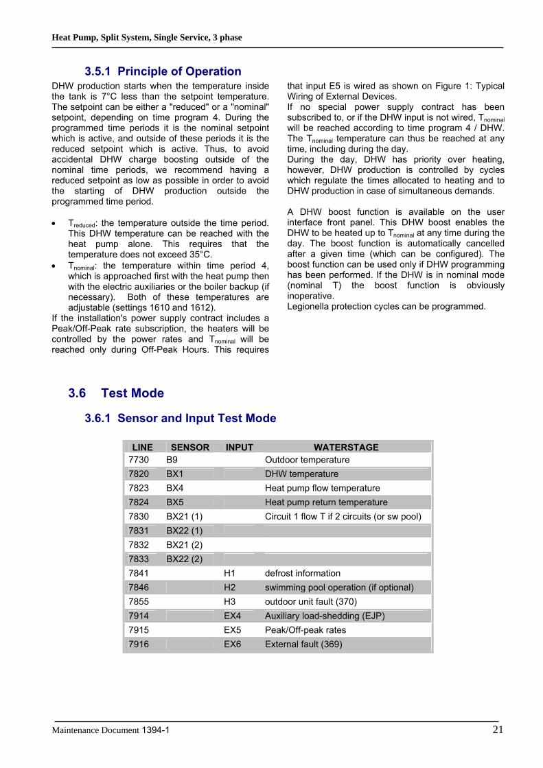
3.5.1 Principle of Operation DHW production starts when the temperature inside the tank is 7°C less than the setpoint temperature. The setpoint can be either a "reduced" or a "nominal" setpoint, depending on time program 4. During the programmed time periods it is the nominal setpoint which is active, and outside of these periods it is the reduced setpoint which is active. Thus, to avoid accidental DHW charge boosting outside of the nominal time periods, we recommend having a reduced setpoint as low as possible in order to avoid the starting of DHW production outside the programmed time period. • Treduced: the temperature outside the time period.
This DHW temperature can be reached with the heat pump alone. This requires that the temperature does not exceed 35°C.
• Tnominal: the temperature within time period 4, which is approached first with the heat pump then with the electric auxiliaries or the boiler backup (if necessary). Both of these temperatures are adjustable (settings 1610 and 1612).
If the installation's power supply contract includes a Peak/Off-Peak rate subscription, the heaters will be controlled by the power rates and Tnominal will be reached only during Off-Peak Hours. This requires
that input E5 is wired as shown on Figure 1: Typical Wiring of External Devices. If no special power supply contract has been subscribed to, or if the DHW input is not wired, Tnominal will be reached according to time program 4 / DHW. The Tnominal temperature can thus be reached at any time, including during the day. During the day, DHW has priority over heating, however, DHW production is controlled by cycles which regulate the times allocated to heating and to DHW production in case of simultaneous demands. A DHW boost function is available on the user interface front panel. This DHW boost enables the DHW to be heated up to Tnominal at any time during the day. The boost function is automatically cancelled after a given time (which can be configured). The boost function can be used only if DHW programming has been performed. If the DHW is in nominal mode (nominal T) the boost function is obviously inoperative. Legionella protection cycles can be programmed.
3.6 Test Mode
3.6.1 Sensor and Input Test Mode
LINE SENSOR INPUT WATERSTAGE 7730 B9 Outdoor temperature 7820 BX1 DHW temperature 7823 BX4 Heat pump flow temperature 7824 BX5 Heat pump return temperature 7830 BX21 (1) Circuit 1 flow T if 2 circuits (or sw pool) 7831 BX22 (1) 7832 BX21 (2) 7833 BX22 (2) 7841 H1 defrost information 7846 H2 swimming pool operation (if optional) 7855 H3 outdoor unit fault (370) 7914 EX4 Auxiliary load-shedding (EJP) 7915 EX5 Peak/Off-peak rates 7916 EX6 External fault (369)

Heat Pump, Split System, Single Service, 3 phase
22 Maintenance Document 1394-1
3.6.2 Output Test Mode
LINE OUTPUT WATERSTAGE 7700 QX23 (1) Circuit 1 heating pump or swimming pool selection valve QX21 (1) Open mixing valve 1 QX22 (1) Close mixing valve 1 QX1 QX2 DHW heating circuiting pump (if connected) QX3 Circuit 2 heating pump QX4 DHW selection valve QX5 Boiler selection valve (or heater 1) QX6 Boiler (or heater 2) QX23 (2) QX21 (2) QX22 (2) QX7 DHW electrical auxiliary 7710 UX Output test UX % 7711 UX Voltage signal UX 7721 DO 1 Heating (or cooling) mode 7722 DO 2 Outdoor unit operation
Heat Pump, Split System, Single Service, 3 phase
Maintenance Document 1394-1 23
4 Faults
4.1 Fault List
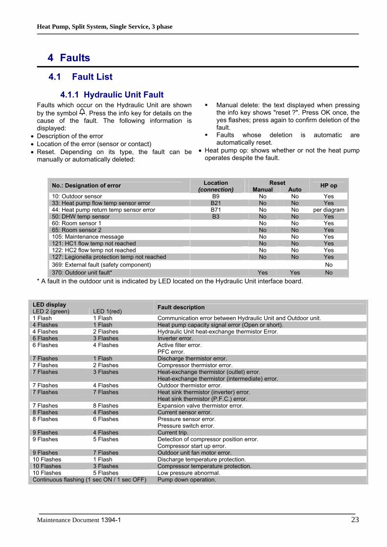
4.1.1 Hydraulic Unit Fault Faults which occur on the Hydraulic Unit are shown by the symbol . Press the info key for details on the cause of the fault. The following information is displayed:
• Description of the error • Location of the error (sensor or contact) • Reset. Depending on its type, the fault can be
manually or automatically deleted:
Manual delete: the text displayed when pressing the info key shows "reset ?". Press OK once, the yes flashes; press again to confirm deletion of the fault.
Faults whose deletion is automatic are automatically reset.
• Heat pump op: shows whether or not the heat pump operates despite the fault.
Reset No.: Designation of error Location (connection) Manual Auto
HP op
10: Outdoor sensor B9 No No Yes 33: Heat pump flow temp sensor error B21 No No Yes 44: Heat pump return temp sensor error B71 No No per diagram50: DHW temp sensor B3 No No Yes 60: Room sensor 1 No No Yes 65: Room sensor 2 No No Yes 105: Maintenance message No No Yes 121: HC1 flow temp not reached No No Yes 122: HC2 flow temp not reached No No Yes 127: Legionella protection temp not reached No No Yes 369: External fault (safety component) No 370: Outdoor unit fault* Yes Yes No
* A fault in the outdoor unit is indicated by LED located on the Hydraulic Unit interface board.
LED display LED 2 (green) LED 1(red)
Fault description
1 Flash 1 Flash Communication error between Hydraulic Unit and Outdoor unit. 4 Flashes 1 Flash Heat pump capacity signal error (Open or short). 4 Flashes 2 Flashes Hydraulic Unit heat-exchange thermistor Error. 6 Flashes 3 Flashes Inverter error. 6 Flashes 4 Flashes Active filter error.
PFC error. 7 Flashes 1 Flash Discharge thermistor error. 7 Flashes 2 Flashes Compressor thermistor error. 7 Flashes 3 Flashes Heat-exchange thermistor (outlet) error.
Heat-exchange thermistor (intermediate) error. 7 Flashes 4 Flashes Outdoor thermistor error. 7 Flashes 7 Flashes Heat sink thermistor (inverter) error.
Heat sink thermistor (P.F.C.) error. 7 Flashes 8 Flashes Expansion valve thermistor error. 8 Flashes 4 Flashes Current sensor error. 8 Flashes 6 Flashes Pressure sensor error.
Pressure switch error. 9 Flashes 4 Flashes Current trip. 9 Flashes 5 Flashes Detection of compressor position error.
Compressor start up error. 9 Flashes 7 Flashes Outdoor unit fan motor error. 10 Flashes 1 Flash Discharge temperature protection. 10 Flashes 3 Flashes Compressor temperature protection. 10 Flashes 5 Flashes Low pressure abnormal. Continuous flashing (1 sec ON / 1 sec OFF) Pump down operation.

Heat Pump, Split System, Single Service, 3 phase
24 Maintenance Document 1394-1
Faults external to the heat pump Any safety device (e.g. thermostat pressure switch) wired to input Ex6 (E20) allows external problems to be reported and the heat pump to be immediately
stopped. For example, a safety thermostat on the heating floor can be wired to input Ex6 (E20) to avoid excessively high temperatures in the floor.
Figure 1: Typical Wiring of External Devices
If the control unit does not provide a potential-free contact, the contact will have to be relayed to obtain an equivalent wiring.
In any case, you should refer to the manuals for the external devices (e.g. load shedders, electricity meters) to perform the wiring.
…
Phase
Neutral
Heat pum
p connecting blocks
… X
5 X6 X
7 X8
to inputs Ex4, Ex5 or EX6
External device contact
(e.g. load-shedder,
electricity meter)
Heat pump Hydraulic Unit

Heat Pump, Split System, Single Service, 3 phase
Maintenance Document 1394-1 25
4.1.2 Outdoor Unit Fault When the system is switched back on after a power outage, the Hydraulic Unit may display fault 370 for a few tens of seconds. This is not a serious problem. It simply means that the outdoor unit is running its tests. Once the tests have been completed, the fault should disappear.
If it doesn't, if a fault has occurred on the outdoor unit as indicated by the Hydraulic Unit, you must remove the front (right-hand) facing from the outdoor unit. Faults are coded by LED flashes. Error messages are listed in the table below:
On the outdoor unit When an error occurs: - The diode “ERROR” (2) blinks
Press once on the switch “ENTER” (SW4) - The “ERROR” (2) diode blinks several times depending on the error’s type
Location of switches and diodes on outdoor unit
LED display on the outdoor unit
LED display Hydraulic Unit Diagnosis Clear
Green Red Outdoor unit
Off Serial reverse transfer error. 1
1 flash 1 flash 1 flash Serial forward transfer error. 2
4 flashes 1 flash 22 flashes Heat pump capacity signal error 4 4 flashes 2 flashes 22 flashes Hydraulic Unit Heat ex. Sensor error 5 6 flashes 3 flashes 18 flashes Inverter error. 20 6 flashes 4 flashes 19 flashes P.F.C. error. 27 7 flashes 1 flash 2 flashes Discharge thermistor error. 7 7 flashes 2 flashes 8 flashes Compressor thermistor error. 11
5 flashes Heat-exchange thermistor (intermediate) error. 12 7 flashes 3 flashes
4 flashes Heat-exchange thermistor (outlet) error. 8 7 flashes 4 flashes 7 flashes Outdoor temperature thermistor error. 9
9 flashes Heat sink thermistor (inverter) error. 10 7 flashes 7 flashes
10 flashes Heat sink thermistor (P.F.C.) error. 13 7 flashes 8 flashes 6 flashes Expansion valve thermistor error. 14 8 flashes 6 flashes 3 flashes Pressure sensor error. 24 9 flashes 4 flashes 13 flashes Current trip (permanent stoppage). 15
14 flashes Detection of compressor position error (permanent stoppage). 33 9 flashes 5 flashes
15 flashes Compressor start up error (permanent stoppage). 17 16 flashes Outdoor unit fan 1 motor error.
9 flashes 7 flashes 17 flashes Outdoor unit fan 2 motor error.
18
10 flashes 1 flash 11 flashes Discharge temperature protection (permanent stoppage). 22 10 flashes 3 flashes 12 flashes Compressor temperature protection (permanent stoppage). 25 10 flashes 5 flashes 20 flashes Low pressure abnormal. 26

Heat Pump, Split System, Single Service, 3 phase
26 Maintenance Document 1394-1
4.2 Outdoor Unit Clearing This section describes the techniques which can be used to identify the failure.
4.2.1 Failures with Error Code Clear 1: Serial reverse transfer error Hydraulic Unit LED: Green 1 flash / Red 1 flash Outdoor Unit LED: Off Probable causes:
• Misconnection. • External cause. • Main PCB failure.
Check:
1-1. Stop the system and start it again (disconnection time 1min): Is the error still displayed?
YES NO
3. Check the power supply voltage: - Check that an AC 198 – 264 V voltage exists between terminals 1 and 2, L1 and N, L2 and N, L3 and N on the outdoor unit terminal block.
OK
4. Check the serial signal: - Check the voltage between terminals 2 and 3 of the outdoor terminal block. The voltage must fluctuate between AC 70 V and AC 130 V. - If it doesn't, replace Main PCB.
OK
1-2. Check for external causes: - Check the system's overall isolation. - Check for any equipment generating electromagnetic waves which interfere with the communication between the hydraulic unit and the outdoor unit.
2. Check the connections: - Check the connection between the hydraulic unit and the outdoor unit. - Check the connections between the outdoor unit main board and the active filter board.

Heat Pump, Split System, Single Service, 3 phase
Maintenance Document 1394-1 27
Clear 2: Serial forward transfer error Hydraulic Unit LED: Green 1 flash / Red 1 flash Outdoor Unit LED: 1 flash Probable causes:
• Misconnection. • External cause. • Interface PCB failure.
Check:
1-1. Stop the system and start it again (disconnection time 1min): Is the error still displayed?
YES NO
3. Check the power supply voltage: - Check that an AC 198 – 264 V voltage exists between terminals 1 and 2, L1 and N, L2 and N, L3 and N on the outdoor unit terminal block.
OK
4. Check the serial signal: - Check the voltage between terminals 2 and 3 of the outdoor terminal block. The voltage must fluctuate between AC 70 V and AC 130 V. - If it doesn't, replace Interface PCB.
OK
1-2. Check for external causes: - Check the system's overall isolation. - Check for any equipment generating electromagnetic waves which interfere with the communication between the hydraulic unit and the outdoor unit.
2. Check the connections: - Check the connection between the hydraulic unit and the outdoor unit. - Check the connections between the outdoor unit main board and the active filter board.

Heat Pump, Split System, Single Service, 3 phase
28 Maintenance Document 1394-1
Clear 4: Heat pump capacity signal error Hydraulic Unit LED: Green 4 flashes / Red 1 flash Outdoor Unit LED: 22 flashes Probable causes:
• Misconnection. • Sensor failure. • Interface PCB failure.
Check:
1. Check connection interface PCB and Heat pump regulator PCB: - See if the connector has been disconnected. - See if the connection is correct. - Check for any damage on the sensor cable.
After solving the misconnection problem, switch the heat pump back on.
2. Check resistance value: 3 pin of CN22 – M < 10Ω
OK
3. Replace interface PCB: If check point 1 and 2 do not improve the symptom, replace Interface PCB.
OK

Heat Pump, Split System, Single Service, 3 phase
Maintenance Document 1394-1 29
Clear 5: Hydraulic Unit Heat exchanger thermistor error Hydraulic Unit LED: Green 4 flashes / Red 2 flashes Outdoor Unit LED: 22 flashes Probable causes: • Misconnection. • Sensor failure. • Interface PCB failure. Check:
1. Check the sensor connection: - See if the connector has been removed - See if the connection is correct - Check for any damage on the sensor cable.
After solving the misconnection problem, switch the heat pump back on.
2. Remove the sensor and check its resistance value : - Check the resistance value. Temperature (°C) 0 5 10 15 20 25 30 35 40 45 50 Resistance (kΩ) 176 134 103 80,3 62,9 49,7 39,6 31,7 25,6 20,8 17,1 - If the thermistor is faulty, replace it.
OK
3. Check the electronic board voltage: - Make sure circuit diagram of hydraulic unit and check terminal voltage at thermistor (DC5.0V)
- If there is no voltage, replace Interface PCB.
OK

Heat Pump, Split System, Single Service, 3 phase
30 Maintenance Document 1394-1
Clear 7: Discharge thermistor error Hydraulic Unit LED: Green 7 flashes / Red 1 flash Outdoor Unit LED: 2 flashes Probable causes:
• Misconnection. • Sensor failure. • Main PCB failure.
Check:
1. Check the sensor connection: - See if the connector has been disconnected. - See if the connection is correct. - Check for any damage on the sensor cable.
After solving the misconnection problem, switch the heat pump back on.
2. Remove the sensor and check its resistance value: - Check the resistance value Temperature (°C) 0 5 10 15 20 30 40 50 Resistance (kΩ) 168 130 101 79 63 40 26,3 17,8 Temperature (°C) 60 70 80 90 100 120 Resistance (kΩ) 12,3 8,7 6,3 4,6 3,4 2 - If the thermistor is faulty, replace it.
OK
3. Check the electronic board voltage: Make sure circuit diagram of outdoor unit and check terminal voltage at thermistor (DC5.0V)
- If there is no voltage, replace Main PCB.
OK
Heat Pump, Split System, Single Service, 3 phase
Maintenance Document 1394-1 31
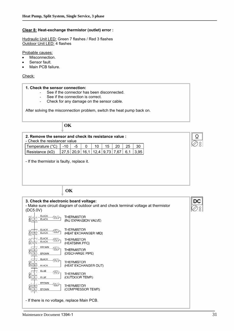
Clear 8: Heat-exchange thermistor (outlet) error : Hydraulic Unit LED: Green 7 flashes / Red 3 flashes Outdoor Unit LED: 4 flashes Probable causes: • Misconnection. • Sensor fault. • Main PCB failure. Check:
1. Check the sensor connection: - See if the connector has been disconnected. - See if the connection is correct. - Check for any damage on the sensor cable.
After solving the misconnection problem, switch the heat pump back on.
2. Remove the sensor and check its resistance value : - Check the resistancer value Temperature (°C) -10 -5 0 10 15 20 25 30 Resistance (kΩ) 27,5 20,9 16,1 12,4 9,73 7,67 6,1 3,95 - If the thermistor is faulty, replace it.
3. Check the electronic board voltage: - Make sure circuit diagram of outdoor unit and check terminal voltage at thermistor (DC5.0V)
- If there is no voltage, replace Main PCB.
OK
OK

Heat Pump, Split System, Single Service, 3 phase
32 Maintenance Document 1394-1
Clear 9: Outdoor temperature thermistor error Hydraulic Unit LED: Green 7 flashes / Red 4 flashes Outdoor Unit LED: 7 flashes Probable causes:
• Misconnection. • Sensor failure. • Main PCB failure.
Check:
1. Check the sensor connection : - See if the connector has been disconnected. - See if the connection is correct. - Check for any damage on the sensor cable.
After solving the misconnection problem, switch the heat pump back on.
2. Remove the sensor and check its resistance value : - Check the resistance value. Temperature (°C) -20 -10 -5 0 5 10 15 20 30 40 50 60 70 Resistance (kΩ) 115 62,3 46,6 35,2 26,9 20,7 16,1 12,6 7,97 5,18 3,45 2,36 1,65 - If the thermistor is faulty, replace it.
OK
3. Check the electronic board voltage: - Make sure circuit diagram of outdoor unit and check terminal voltage at thermistor (DC5.0V)
- If there is no voltage, replace Main PCB.
OK
Heat Pump, Split System, Single Service, 3 phase
Maintenance Document 1394-1 33
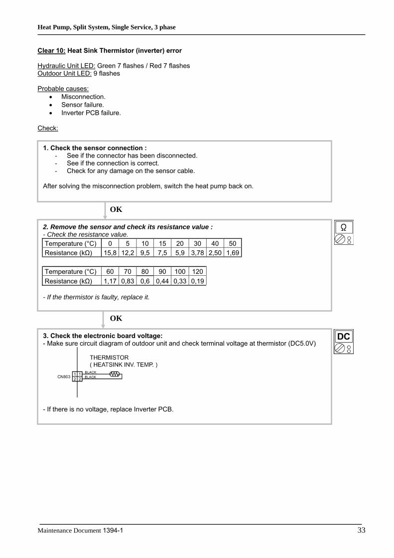
Clear 10: Heat Sink Thermistor (inverter) error Hydraulic Unit LED: Green 7 flashes / Red 7 flashes Outdoor Unit LED: 9 flashes Probable causes:
• Misconnection. • Sensor failure. • Inverter PCB failure.
Check:
1. Check the sensor connection : - See if the connector has been disconnected. - See if the connection is correct. - Check for any damage on the sensor cable.
After solving the misconnection problem, switch the heat pump back on.
2. Remove the sensor and check its resistance value : - Check the resistance value. Temperature (°C) 0 5 10 15 20 30 40 50 Resistance (kΩ) 15,8 12,2 9,5 7,5 5,9 3,78 2,50 1,69 Temperature (°C) 60 70 80 90 100 120 Resistance (kΩ) 1,17 0,83 0,6 0,44 0,33 0,19 - If the thermistor is faulty, replace it.
OK
3. Check the electronic board voltage: - Make sure circuit diagram of outdoor unit and check terminal voltage at thermistor (DC5.0V)
- If there is no voltage, replace Inverter PCB.
OK

Heat Pump, Split System, Single Service, 3 phase
34 Maintenance Document 1394-1
Clear 11: Compressor thermistor error Hydraulic Unit LED: Green 7 flashes / Red 2 flashes Outdoor Unit LED: 8 flashes Probable causes: • Misconnection. • Sensor failure. • Main PCB failure. Check:
1. Check the sensor connection: - See if the connector has been removed - See if the connection is correct - Check for any damage on the sensor cable.
After solving the misconnection problem, switch the heat pump back on.
2. Remove the sensor and check its resistance value : - Check the resistance value. Temperature (°C) 0 5 10 15 20 30 40 50 Resistance (kΩ) 168 130 101 79 63 40 26,3 17,8 Temperature (°C) 60 70 80 90 100 120 Resistance (kΩ) 12,3 8,7 6,3 4,6 3,4 2 - If the thermistor is faulty, replace it.
OK
3. Check the electronic board voltage: - Make sure circuit diagram of outdoor unit and check terminal voltage at thermistor (DC5.0V)
- If there is no voltage, replace Main PCB.
OK

Heat Pump, Split System, Single Service, 3 phase
Maintenance Document 1394-1 35
Clear 12: Heat-exchange thermistor (intermediate) error Hydraulic Unit LED: Green 7 flashes / Red 3 flashes Outdoor Unit LED: 5 flashes Probable causes: • Misconnection. • Sensor failure. • Main PCB failure. Check:
1. Check the sensor connection: - See if the connector has been disconnected. - See if the connection is correct. - Check for any damage on the sensor cable.
After solving the misconnection problem, switch the heat pump back on.
2. Remove the sensor and check its resistance value : - Check the resistance value Temperature (°C) -10 -5 0 10 15 20 25 30 Resistance (kΩ) 27,5 20,9 16,1 12,4 9,73 7,67 6,10 3,95 - If the thermistor is faulty, replace it.
3. Check the electronic board voltage: - Make sure circuit diagram of outdoor unit and check terminal voltage at thermistor (DC5.0V)
- If there is no voltage, replace Main PCB.
OK
OK

Heat Pump, Split System, Single Service, 3 phase
36 Maintenance Document 1394-1
Clear 13: Heat sink thermistor (P.F.C.) error Hydraulic Unit LED: Green 7 flashes / Red 7 flashes Outdoor Unit LED: 10 flashes Probable causes: • Misconnection. • Sensor failure. • Main PCB failure. Check:
1. Check the sensor connection: - See if the connector has been removed - See if the connection is correct - Check for any damage on the sensor cable.
After solving the misconnection problem, switch the heat pump back on.
2. Remove the sensor and check its resistance value : - Check the resistance value. Temperature (°C) 0 5 10 15 20 30 40 50 Resistance (kΩ) 15,8 12,2 9,5 7,5 5,9 3,78 2,50 1,69 Temperature (°C) 60 70 80 90 100 110 120 Resistance (kΩ) 1,17 0,83 0,60 0,44 0,33 0,25 0,19 - If the thermistor is faulty, replace it.
OK
3. Check the electronic board voltage: - Make sure circuit diagram of outdoor unit and check terminal voltage at thermistor (DC5.0V)
- If there is no voltage, replace Main PCB.
OK
Heat Pump, Split System, Single Service, 3 phase
Maintenance Document 1394-1 37
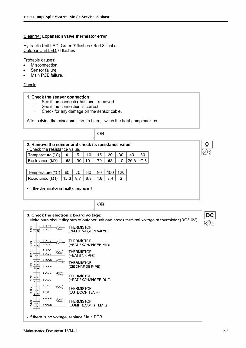
Clear 14: Expansion valve thermistor error Hydraulic Unit LED: Green 7 flashes / Red 8 flashes Outdoor Unit LED: 6 flashes Probable causes: • Misconnection. • Sensor failure. • Main PCB failure. Check:
1. Check the sensor connection: - See if the connector has been removed - See if the connection is correct - Check for any damage on the sensor cable.
After solving the misconnection problem, switch the heat pump back on.
2. Remove the sensor and check its resistance value : - Check the resistance value. Temperature (°C) 0 5 10 15 20 30 40 50 Resistance (kΩ) 168 130 101 79 63 40 26,3 17,8 Temperature (°C) 60 70 80 90 100 120 Resistance (kΩ) 12,3 8,7 6,3 4,6 3,4 2 - If the thermistor is faulty, replace it.
OK
3. Check the electronic board voltage: - Make sure circuit diagram of outdoor unit and check terminal voltage at thermistor (DC5.0V)
- If there is no voltage, replace Main PCB.
OK

Heat Pump, Split System, Single Service, 3 phase
38 Maintenance Document 1394-1
Clear 15: Current trip (permanent stoppage) Hydraulic Unit LED: Green 9 flashes / Red 4 flashes Outdoor Unit LED: 13 flashes Probable causes:
• Connection failure. • Outdoor Heat Exchanger clogged. • Outdoor Fan operation failure. • Compressor failure. • Inverter PCB failure.
Check:
1. Check connections condition in control unit: - Check if the terminal connection is loose. - Check if connector is removed. - Check if connector is erroneous connection. - Check if cable is open. Upon correcting the removed connector or mis-wiring, reset the power.
OK
3. Check Outdoor Fan: - Check Outdoor Fan Motor. (Refer to Clear 18) If the Fan Motor is failure, replace it.
OK
4. Check Compressor: Refer to “Service parts information 2 : Inverter compressor If it is abnormal, replace compressor.
OK
2. Check Outdoor Heat Exchanger: - Is there any obstructing the air flow route? - Is there any clogging of outdoor unit Heat Exchanger? If clogged, clear the clog.
5. Replace Inverter PCB: If Check Point 1 ~ 4 do not improve the symptom, replace Inverter PCB.
OK

Heat Pump, Split System, Single Service, 3 phase
Maintenance Document 1394-1 39
Clear 17: Compressor startup error (permanent stoppage) Hydraulic Unit LED: Green 9 flashes / Red 5 flashes Outdoor Unit LED: 15 flashes Probable causes:
• Misconnection of the various electrical components. • Inverter PCB failure. • Compressor failure.
Check:
2. Check Compressor: Refer to “Service parts information 2 : Inverter compressor If it is abnormal, replace compressor.
3. Replace the electronic board : - If steps 1 and 2 do not solve the problem, replace Inverter PCB.
OK
1. Check connections condition in control unit: - Check if the terminal connection is loose. - Check if connector is removed. - Check if connector is erroneous connection. - Check if cable is open. Upon correcting the removed connector or mis-wiring, reset the power.
OK

Heat Pump, Split System, Single Service, 3 phase
40 Maintenance Document 1394-1
Clear 18: Fan motor error (permanent stoppage) Hydraulic Unit LED: Green 9 flashes / Red 7 flashes Outdoor Unit LED: 16 flashes (fan 1), 17 flashes (fan 2) Probable causes:
• Fan motor failure. • Motor protection. • Main PCB failure.
Check:
1. Check fan rotation: - Switch off the heat pump and rotate the fan manually. - If the fan or bearings are faulty, replace them.
2. Check the ambient temperature around the motor: - Check excessively high temperature around the fan. Wait until the temperature comes down again and switch the fan back on.
3. Check the main board output voltage: - On the outdoor unit, check the output voltage (DC) of the following connectors:
Terminals Voltage 1 (red)/ 3 (black) 250 400V
4 (white)/3 (black) 15 ±2V
If the voltage is incorrect, replace Main PCB.
OK
OK
Heat Pump, Split System, Single Service, 3 phase
Maintenance Document 1394-1 41
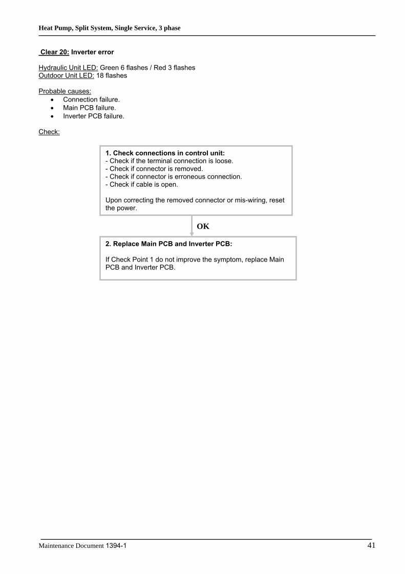
Clear 20: Inverter error Hydraulic Unit LED: Green 6 flashes / Red 3 flashes Outdoor Unit LED: 18 flashes Probable causes:
• Connection failure. • Main PCB failure. • Inverter PCB failure.
Check:
1. Check connections in control unit: - Check if the terminal connection is loose. - Check if connector is removed. - Check if connector is erroneous connection. - Check if cable is open. Upon correcting the removed connector or mis-wiring, reset the power.
2. Replace Main PCB and Inverter PCB: If Check Point 1 do not improve the symptom, replace Main PCB and Inverter PCB.
OK

Heat Pump, Split System, Single Service, 3 phase
42 Maintenance Document 1394-1
Clear 22: Discharge temperature protection (permanent stoppage) Hydraulic Unit LED: Green 10 flashes / Red 1 flashes Outdoor Unit LED: 11 flashes Probable causes:
• Valve is close. • EEV failure. • Gas leak, less. • Discharge Thermistor failure. • Outdoor Fan operation failure. • Outdoor Heat Exchanger clogged.
Check:
1. Check if gas valve is open: If it is not open, open it and check the operation.
2. Check EEV and Strainer: Are EEV and Strainer open? If EEV or Strainer is defective, replace it.
OK
Cooling mode
1. Check if liquid valve is open: If it is not open, open it and check the operation.
2. Check EEV and Strainer: Are EEV and Strainer open? If EEV or Strainer is defective, replace it.
OK
Heating mode
3. Check if gas leak or less gas: Measure gas pressure, if there is a leak, correct it. If recharging refrigerant, make sure to perform vacuuming and recharge the specified amount.
OK OK
4. Check Discharge Pipe Thermistor: - Is it on the holder? - Is there a cable pinched? Check characteristics of thermistor (Refer to Clear 7), If defective, replace the thermistor
OK
5. Check Outdoor Heat Exchanger: - Is there any obstructing the air flow route? - Is there any clogging of outdoor unit Heat Exchanger? If clogged, clear the clog.
OK
6. Check Outdoor Fan: Check Outdoor Fan Motor. (Refer to Clear 18) If the Fan Motor is failure, replace it.
OK

Heat Pump, Split System, Single Service, 3 phase
Maintenance Document 1394-1 43
Clear 24: Pressure sensor error Hydraulic Unit LED: Green 8 flashes / Red 6 flashes Outdoor Unit LED: 3 flashes Probable causes:
• Connector connection failure. • Pressure Sensor failure. • Main PCB failure.
Check:
2. Check output voltage of Main PCB : Check voltage of Main PCB (Measure at Main PCB side connector) 1 pin(Red) - 3 pin(Black) DC5V +/- 5%
If the voltage is not correct, replace Main PCB.
OK
3. Check output voltage of Pressure Sensor Check voltage of Main PCB (Measure at Main PCB side connector) 2 pin(White) - 3 pIn(Black) Voltage is refer to the following graph.
If the voltage is not correct, replace Presure Sensor.
OK
1. Check connection of the Pressure Sensor: - Check if the terminal connection is loose. - Check if connector is removed. - Check if connector is erroneous connection. - Check if cable is open. Upon correcting the removed connector or mis-wiring, reset the power.
Heat Pump, Split System, Single Service, 3 phase
44 Maintenance Document 1394-1
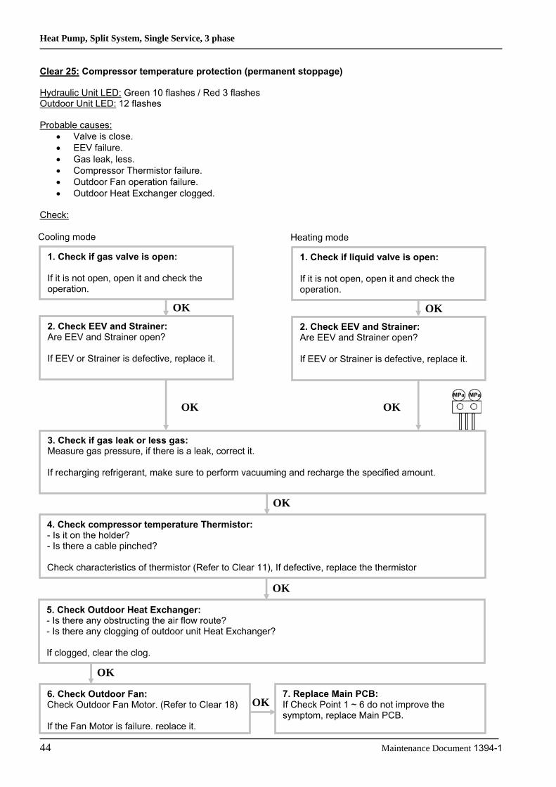
Clear 25: Compressor temperature protection (permanent stoppage) Hydraulic Unit LED: Green 10 flashes / Red 3 flashes Outdoor Unit LED: 12 flashes Probable causes:
• Valve is close. • EEV failure. • Gas leak, less. • Compressor Thermistor failure. • Outdoor Fan operation failure. • Outdoor Heat Exchanger clogged.
Check:
1. Check if gas valve is open: If it is not open, open it and check the operation.
2. Check EEV and Strainer: Are EEV and Strainer open? If EEV or Strainer is defective, replace it.
OK
Cooling mode
1. Check if liquid valve is open: If it is not open, open it and check the operation.
2. Check EEV and Strainer: Are EEV and Strainer open? If EEV or Strainer is defective, replace it.
OK
Heating mode
3. Check if gas leak or less gas: Measure gas pressure, if there is a leak, correct it. If recharging refrigerant, make sure to perform vacuuming and recharge the specified amount.
OK OK
4. Check compressor temperature Thermistor: - Is it on the holder? - Is there a cable pinched? Check characteristics of thermistor (Refer to Clear 11), If defective, replace the thermistor
OK
5. Check Outdoor Heat Exchanger: - Is there any obstructing the air flow route? - Is there any clogging of outdoor unit Heat Exchanger? If clogged, clear the clog.
OK
6. Check Outdoor Fan: Check Outdoor Fan Motor. (Refer to Clear 18) If the Fan Motor is failure, replace it.
OK
7. Replace Main PCB: If Check Point 1 ~ 6 do not improve the symptom, replace Main PCB.
OK

Heat Pump, Split System, Single Service, 3 phase
Maintenance Document 1394-1 45
Clear 26: Low pressure abnormal Hydraulic Unit LED: Green 10 flashes / Red 5 flashes Outdoor Unit LED: 20 flashes Probable causes:
• Connector connection failure. • Pressure Sensor failure. • Main PCB failure. • Gas leak, less.
Check:
2. Check output voltage of Main PCB : Check voltage of Main PCB (Measure at Main PCB side connector) 1 pin(Red) - 3 pin(Black) DC5V +/- 5%
If the voltage is not correct, replace Main PCB.
OK
3. Check if gas leak or less gas Measure Gas pressure, if there is a leak, correct it. If recharging refrigerant, make sure to perform vacuuming and recharge the specified amount.
OK
1. Check connection of the Pressure Sensor: - Check if the terminal connection is loose. - Check if connector is removed. - Check if connector is erroneous connection. - Check if cable is open. Upon correcting the removed connector or mis-wiring, reset the power.
OK
4. Replace Pressure Sensor If Check Point 1 ~ 3 do not improve the symptom, replace Pressure Sensor.

Heat Pump, Split System, Single Service, 3 phase
46 Maintenance Document 1394-1
Clear 27: P.F.C. error Hydraulic Unit LED: Green 6 flashes / Red 4 flashes Outdoor Unit LED: 19 flashes Probable causes:
• Connector connection failure. • Main PCB failure. • PFC PCB failure.
Check:
2. Check output voltage of Main PCB : Check voltage of Main PCB (Measure at Main PCB side connector) 1 pin(brown) - 2 pin(Red) DC5V +/- 5% If the voltage is not correct, replace Main PCB.
OK
3. Replace PFC PCB If Check Point 1, 2 do not improve the symptom, replace PFC PCB.
OK
1. Check connections of between Main PCB and PFC PCB: - Check if the terminal connection is loose. - Check if connector is removed. - Check if connector is erroneous connection. - Check if cable is open. Upon correcting the removed connector or mis-wiring, reset the power.

Heat Pump, Split System, Single Service, 3 phase
Maintenance Document 1394-1 47
Clear 33: Detection of compressor position error (permanent stoppage) Hydraulic Unit LED: Green 9 flashes / Red 5 flashes Outdoor Unit LED: 14 flashes Probable causes:
• Misconnection. • Inverter PCB failure.
Check:
1. Check connections condition in control unit: - Check if the terminal connection is loose. - Check if connector is removed. - Check if connector is erroneous connection. - Check if cable is open. Upon correcting the removed connector or mis-wiring, reset the power.
OK
2. Replace the electronic board : - If steps 1 do not solve the problem, replace Inverter PCB.

Heat Pump, Split System, Single Service, 3 phase
48 Maintenance Document 1394-1
4.2.2 Failures With No Error Code Clear 35: No voltage on Hydraulic Unit Probable causes:
• Power supply fault. • External causes. • Faulty electrical components.
Check:
1. Check the installation : - Is the circuit breaker cut off? - Check the wiring.
2. Check for external causes on the Hydraulic Unit and outdoor unit (noise or voltage drop): - Check for any other electrical device on the same electric circuit which might cause a drop in
voltage. - Check for any current leaks. - Check for any equipment generating electromagnetic waves which interfere with the
communication between the Hydraulic Unit and the outdoor unit.
3. Check the electrical components:
If all of these checks are unsuccessful, replace Interface PCB.
OK
OK
OK
- Check that a voltage between AC 198 and AC 264 V exists between terminals 1 and 2 on the Hydraulic Unit terminal block.
NO
- Check Interface PCB for : o either the fuse (F1). o or the varistor (VA1). Fault: overvoltage - external causes - power supply to be
checked). - Replace the faulty component (if the varistor is blown, the PCB must be replaced).
YES
Heat Pump, Split System, Single Service, 3 phase
Maintenance Document 1394-1 49
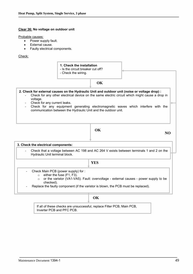
Clear 36: No voltage on outdoor unit Probable causes:
• Power supply fault. • External cause. • Faulty electrical components.
Check:
3. Check the electrical components:
2. Check for external causes on the Hydraulic Unit and outdoor unit (noise or voltage drop) : - Check for any other electrical device on the same electric circuit which might cause a drop in
voltage. - Check for any current leaks. - Check for any equipment generating electromagnetic waves which interfere with the
communication between the Hydraulic Unit and the outdoor unit.
OK
OK
1. Check the installation - Is the circuit breaker cut off? - Check the wiring.
NO
If all of these checks are unsuccessful, replace Filter PCB, Main PCB, Inverter PCB and PFC PCB.
OK
- Check that a voltage between AC 198 and AC 264 V exists between terminals 1 and 2 on the Hydraulic Unit terminal block.
- Check Main PCB (power supply) for : o either the fuse (F1, F3). o or the varistor (VA1-VA5). Fault: overvoltage - external causes - power supply to be
checked). - Replace the faulty component (if the varistor is blown, the PCB must be replaced).
YES

Heat Pump, Split System, Single Service, 3 phase
50 Maintenance Document 1394-1
Clear 38: No heat Probable causes:
• Hydraulic Unit error. • Outdoor unit error. • Influence from the outdoor environment. • Misconnections of connectors and cables. • Refrigeration system fault (not enough gas, clogging, dirty filters).
Check:
2. Check the Hydraulic Unit : - Is the pump operating? - See if the exchanger is not clogged?
3. Check the outdoor unit: - Is the fan rotating at high speed? - Are there any objects blocking the air flow? - Is the outdoor exchanger clogged? - Are the valves open?
4. Check the configuration of the room: - Is the heat pump power suited to the need?
5. Inspect the Hydraulic Unit and outdoor unit installation: - Check the refrigeration connections (length, diameter)
6. Inspect the refrigeration circuit: - See if the dehydrator is clogged (there should be no temperature variation between the dehydrator input and output in normal operating conditions). - Check the electronic expansion valve - Check the compressor
1. The unit provides heating or cooling
No
Is the cooling kit connected ?
Yes
Check the wiring of the cooling kit control wire

Heat Pump, Split System, Single Service, 3 phase
Maintenance Document 1394-1 51
Clear 39: Abnormal noise Probable causes:
• Abnormal installation (outdoor) • Fan failure • Compressor failure.
Checks:
1. The noise comes from the outdoor unit: - Is the unit stable? - Is the protection screen properly mounted?
- Is the propeller broken or distorted? - Has the propeller screw been lost? - Is any object blocking the propeller rotation?
OK
- Check for any vibration noise caused by a bolt. - Check for any sound of contact with a pipe.
OK
- Is the compressor locked?
OK

Heat Pump, Split System, Single Service, 3 phase
52 Maintenance Document 1394-1
4.3 Sensor Values
4.3.1 Outdoor Unit Temperature Sensors Outdoor Heat Exchanger (outlet), Outdoor Heat Exchanger (middle) Temperature (°C) -10 -5 0 10 15 20 25 30 Resistance value (kΩ) 27,5 20,9 16,1 12,4 9,73 7,67 6,1 3,95 Outdoor Discharge Pipe / Compressor / Expansion valve inlet Temperature (°C) 0 5 10 15 20 30 40 50 60 Resistance value (kΩ) 168 130 101 79 63 40 26,3 17,8 12,3 Temperature (°C) 70 80 90 100 120 Resistance value (kΩ) 8,7 6,3 4,6 3,4 2 Outdoor Temperature Temperature (°C) -20 -10 -5 0 5 10 15 20 30 Resistance value (kΩ) 115 62,3 46,6 35,2 26,9 20,7 16,1 12,6 7,97 Temperature (°C) 40 50 60 70 Resistance value (kΩ) 5,18 3,45 2,36 1,65 Heat sink (INV), Heat sink (PFC) Temperature (°C) 0 5 10 15 20 30 40 50 60 Resistance value (kΩ) 15,8 12,2 9,5 7,5 5,9 3,78 2,50 1,69 1,17 Temperature (°C) 70 80 90 100 110 120 Resistance value (kΩ) 0,83 0,60 0,44 0,33 0,25 0,19
4.3.2 Hydraulic Unit Temperature Sensors Heat Exchanger (Condensing sensor) Temperature (°C) 0 5 10 15 20 25 30 35 40 45 50 Resistance value (kΩ) 176 134 103 80,3 62,9 49,7 39,6 31,7 25,6 20,8 17,1 Outdoor sensor Temperature (°C) -20 -15 -10 -5 0 5 10 15 20 Resistance value (kΩ) 7,60 5,85 4,60 3,60 2,85 2,30 1,85 1,50 1,20 Temperature (°C) 25 30 35 40 45 Resistance value (kΩ) 1 0,83 0,70 0,58 0,48 Heat pump flow and return sensor – DHW and heating zone 2 sensor – Swimming pool return sensor Temperature (°C) -15 -10 -5 0 5 10 15 20 25 Resistance value (kΩ) 72,5 55 42 32,5 25 20 15,7 12,5 10 Temperature (°C) 30 35 40 45 50 55 60 65 70 Resistance value (kΩ) 8 6,5 5 4 3,5 3 2,5 2 1,7

Heat Pump, Split System, Single Service, 3 phase
Maintenance Document 1394-1 53
4.4 Service parts information
4.4.1 Service parts information 1 : Compressor
Does not start up
Diagnosis method of compressor (if outdoor unit LED displays error, refer to Failures and clears)
Abnormal noise Stops soon after starting up
Is there open or loose connection cable?
Check connection of compressor, and winding resistance (Refer to the next page). If there is no failure, the defected of compressor is considered (locked compressor due to clogged dirt or less oil).
Replace compressor
Is there open or loose connection cable?
Is gas pipe valve open ? (Low pressure is too low)
Check if refrigerant is leakin. Recharge refrigerant.
Check if stainer is clogged (Parts information 3)
Check inverter PCB, connection of compressor, and winding resistance (refer to the next page). If there is no failure, the defected of compressor is considered (Compression part broken or valve defective).
Replace compressor
Check if vibration noise by loose bolt or contact noise of piping is happening.
Defective compressor can be considered (due to inside dirt clogging or broken component).
Replace compressor

Heat Pump, Split System, Single Service, 3 phase
54 Maintenance Document 1394-1
4.4.2 Service parts information 2 : Inverter compressor Check point 1 : Check connection Check terminal connection of compressor (Loose or incorrect wiring)
Check connection of inverter PCB (Loose or incorrect wiring)
Check point 2 : check winding resistance Check winding resistance on each terminal If the resistance value is 0Ω or infinite, replace compressor.
Check point 3 : replace inverter PCB If check point 1 and 2 do not improve the symptom, replace Inverter PCB.

Heat Pump, Split System, Single Service, 3 phase
Maintenance Document 1394-1 55
4.4.3 Service parts information 3 : Outdoor unit electronic expansion valve (EEV, EEV(INJ))
Check point 1 : Check connection Check connection of connector (Loose connector or open cable)
Check point 2 : Check coil of EEV Remove connector, check each winding resistance of coil.
Read wire Resistance value White-Red Yellow-Red Orange-Red Blue-Red
46Ω +/- 4Ω at 20°C
If resistance value is abnormal, replace EEV.
Check point 3 : Check voltage from main PCB Remove connector and check voltage (DC12V) If it does not appear, replace Main PCB. Check point 4 : Check noise at start up Turn on power and check operation noise. If an abnormal noise does not show, replace Main PCB.
Check point 5 : Check opening and closing operation of valve When valve is closed, it has a temp. (Add period) difference between inlet and outlet.
If it is open, it has no temp. (Add period) difference between inlet and outlet.
There is no refrigerant flow coming to EEV(INJ) while the liquid injection is inactive. Check whether the liquid injection is active before executing check point 5 for EEV(INJ). Check point 6 : Check stainer Stainer normally does not have temperature difference between inlet and outlet as shown in 1, but if there is a difference as shown in 2, there is a possibility of inside clogged. In this case, replace stainer.

Heat Pump, Split System, Single Service, 3 phase
56 Maintenance Document 1394-1
4.4.4 Service parts information 4 : Outdoor unit solenoid valve (SV) Check point 1 : Check connections Check connection of connector (Loose connector or open cable)
Check point 2 : Check solenoid coil Remove connector and check if coil is open (normal resistance value of each coil : 1495+/-7%) If resistance value is abnormal, replace solenoid coil. Check point 3 : Check voltage from main PCB Remove connector and check the voltage (AC230V). If the voltage does not appear, replace Main PCB.
Check point 4 : check opening and closing operation valve Depending on the injection activity, check if valve is operating normally. (When valve opens, ther is no temperature difference between inlet and outlet)
• If the valve closes by removing the connector of the valve which does not close, it is considered to be Main PCB failure. Replace Main PCB.
• If it does not closeby removing connector, there is a
possibility of (1) clogging by dirt, or (2) deformation by the heat at the time of solenoid valve installation. In this case, replace solenoid valve.
SV
SOLENOID COIL (INJ)
BLUE
BLUE
1 2 1 2
CN
104

Heat Pump, Split System, Single Service, 3 phase
Maintenance Document 1394-1 57
4.5 Operating Limits
HEAT PUMP WATERSTAGE 112
WATERSTAGE 140
WATERSTAGE 160
Min/max OT in heat mode (°C)*** -20/35 Heating floor maximum water temperature (°C) 45
LT radiator maximum water temperature (°C) 60
Min/max OT in cooling mode(°C) 8/43 Cooling floor minimum water temperature (°C) 18
Fan coil minimum water temperature (°C) 8
Water circuit max pressure (Bar) 3 Maximum flow rate (l/h) 2400 3000 3400 Minimum flow rate (l/h) 1200 1500 1700 Refrigerant circ max pressure (kPa) 4,2 Min delta T (°C) 4 Max delta T (°C) 8 Outdoor unit Noise level 1 (dBA)* 53 55 56 Outdoor unit Noise level 5 (dBA)** 39 41 42 Outdoor unit air flow rate (m3/h) 3100 x 2
* Acoustic pressure level reading at 1m, in open field, on a reflecting plane. ** Acoustic pressure level reading at 5m, in open field, on a reflecting plane t. *** When the outdoor temperature continuously exceeds 35°C, DHW heating is done by the water heater heating element.
Available Hydraulic Pressures and Flow Rates

Heat Pump, Split System, Single Service, 3 phase
58 Maintenance Document 1394-1
5 Failures
5.1 Hydraulic, Electric and Refrigeration Systems
5.1.1 Hydraulic System If the installation is fitted with a heating floor, the most common failures are those listed below:
FAILURE CASES CONSEQUENCES SOLUTIONS APPLIED BY
Flow pressure too high clean filter or desludge Installer 1- Clogged filter* or sludge in system ∆T too high (>7) clean filter or desludge Installer
Zero flow pressure change pump with warranty if pump is faulty
Service station
current too high (rotor locked) change pump with warranty if pump is faulty
Service station
zero current (winding cut off) change pump with warranty if pump is faulty
Service station
2- Pump out of order
pump stuck release with a screwdriver Installer
Pipe leak. Pipe under warranty if faulty
Service station
3-Leak Low level in expansion vessel
On collector, isolate heating circuits to determine which heating circuit is perforated.
Leak in heating circuit. Floor again.
Installer
On collector, check heating circuit flow/return temps (infrared thermometer)
Clear with test pump
4- Clogged heating circuit (crushed pipe)
Very high difference between floor flow/return temp If no clogged
heating circuit, check for crushing with infrared camera
Call the installer's or floor coverer's responsibility into question
Service station
5- Misbalance Very high difference between floor flow/return temp Rebalance Installer
6- Floor undersized or charge losses too high
Very high difference between floor flow/return temp
On collector, check heating circuit flow/return temps (infrared thermometer)
Call the installer's responsibility into question
Installer or Service station
* Not required and not shown on the device.

Heat Pump, Split System, Single Service, 3 phase
Maintenance Document 1394-1 59
5.1.2 Electrical System Outdoor Unit Overvoltage Check for possible causes in the list below (this list is not exhaustive): • Problem with the compressor • PFC board • Inverter board • Main board • Faulty power relay
Steps to be followed before performing any work on the Inverter module: • First switch off the system using the circuit
breaker at the head of the line. • Remove the unit cover and then remove the
Inverter module cover. • Measure the voltage at the condenser terminals.
You should find a value of 5 Vdc or less. Inspection of the Power Transistor Module (Inverter board) Disconnect the compressor relay and the condenser connection. Measure the resistance value at the points shown on the illustration, and then compare the values observed with those in the table.
Multimeter Resistor
1 MOhmor more
Terminal block

Heat Pump, Split System, Single Service, 3 phase
60 Maintenance Document 1394-1
5.1.3 Refrigeration System Unit produces no heat The unit remains in continuous scanning mode. Initial checks:
Check the settings Are the data sent by the user interface received by the heat pump?
Hydraulic unit electronic circuit sending data to outdoor unit ?
Compressor running ?
Operating pressure OK ?
4-way valve switching ?
Expansion correct ?
Inspect refrigeration lines (clogging)
Hydraulic unit electronic system faulty
Inspect PCB
Charge to balance
Problem solved?
Servicing complete
Valve coil faulty ?
Change expansion valve Change coil
Change 4-way valve after testing
No
Yes
No
Yes
Yes
No
No
No
No
Yes
Yes
No
Yes
Yes

Heat Pump, Split System, Single Service, 3 phase
Maintenance Document 1394-1 61
Outdoor unit does not defrost • Is condensation drain properly discharged
(outdoor unit directly on the ground)? • Are the auxiliaries powered? • In boiler backup mode, is the boiler authorized? • In very cold areas, a fusing resistance value is
recommended. Is the installation regularly subject to micro-outages of power (frequent outages on the mains power system may also cause defrosting problems)?
Is there a peak day clearing (EJP) outage on the installation?
• Does the heat pump regularly switch to high pressure safety mode?
If this occurs at low temperatures (< 5 °C), we recommend checking that the water pump is operating properly.
• Is the charge correct (refer to the
temperature/pressure curve)? Insufficient charging will result in frequent icing. Overcharging will result in frequently switching to HP safety mode.
(If you still have doubts as to the charge, perform the charging with an electronic scale). • Outdoor unit defrosting is controlled by the
exchanger sensor and the controller board. If the defrost sensor is not iced up while the rest of the exchanger is, then: ⇒ Move the sensor between the exchanger blades
to a place where the exchanger is iced up. ⇒ If all these points have been checked, replace the
outdoor controller board.
Note: Outdoor unit defrosting is controlled by the exchanger sensor and the controller board. If no frosting is observed and no anomaly is otherwise noted, the sensor and board must be inspected and the faulty part will have to be replaced. Defrosting
a. Defrost beginning conditions
62’ < t < 240’
Start of heat mode (Compressor ON)
Cumulative compressor operating time
Defrost
(No defrost for 10 min) 1st defrost Subsequent defrosts
240’ < t 17’ < t < 62’ 240’ < t 35’ < t < 240’
O Exch T ≤ -9°C
O Exch T ≤ -5°C
O Exch T ≤ -3°C
O Exch T ≤ -10°C
O Exch T ≤ -3°C
OT – O Exch T >5°C
O Exch T : outdoor unit exchanger temperature OT : outdoor temperature t : Cumulative compressor operating time

Heat Pump, Split System, Single Service, 3 phase
62 Maintenance Document 1394-1
b. Defrost ending conditions With all models, defrosting stops if the exchanger temperature is above 10 °C or if the defrosting time is over 15 minutes).
Crankcase heater When the outdoor exchanger temperature is below -5°C and the heating mode has been stopped for 30 minutes, the compressor windings are powered and maintain the compressor temperature.
When operation has started and the temperature becomes higher than -3°C, heating stops.
5.2 Compressor Operating Checks Using a multimeter set to mega ohm, check that the resistance value across the windings is identical irrespective of the phase (between U and V, V and W, W and U). This value should be approx. 1 Ohm.
Check that resistance between each phase and the earth is infinite. The result should be clear (you should not see the displayed value increasing slowly up to a value greater than the multimeter maximum rating).
5.3 Refrigeration Circuit Leak Test The new regulation requires annual leak testing of installations with a refrigerant charge higher than 2kg.
Leak testing is to be performed with an approved detector that has been appropriately calibrated.
5.4 Troubleshooting The heat pump is not operating at all (no illuminated indicator): Are the power supply voltage and frequency
normal? Is the connection to mains correct? Have all the connectors been properly inserted? Are the fuses on the outdoor unit still operating?
If not, change the bad fuse(s). Is the connection between the outdoor unit and
the Hydraulic Unit correct? Do you read 230V AC between terminals 1 and 2 of the Hydraulic Unit terminal block?
Do you read 230V AC at the transformer primary on the Hydraulic Unit? If not, change the board.
Is there any voltage on the transformer secondary on the Hydraulic Unit? If not, check the thermal fuse. If the fuse is good, the error comes from the board.

Heat Pump, Split System, Single Service, 3 phase
Maintenance Document 1394-1 63
6 Control Settings
6.1 General The settings described below are those which can be modified by the user. We wish to remind you that changing the settings below may cause the heat pump to behave in an undesirable way. A testing period should be conducted before the permanent settings of the heat pump are confirmed. This may require a number of changes to be made by the installer.
There are 4 access levels:
U: end-user level I: commissioning level (installer start-up) S: engineer level (specialist) C: OEM level (manufacturer) (not available)
6.2 Function Table
COMMAND LINE
ACCESS LEVEL FUNCTION SETTING RANGE FACTORY
SETTING
Time of day and date 1 U Hour/minutes 00:00…23:59 2 U Day/month 01.01…31.12 3 U Year 1900…2099 5 S Start of summertime 01.01…31.12 25.03 6 S End of summertime 01.01…31.12 25.10
Operator section 20 U Language English
22 S Info Temporarily / Permanent Temporarily
26 S Operation lock Off/on Off 27 S Programming lock Off/on Off 28 I Direct adjustment Auto/confirm Confirm
40* I Used as
Room unit 1 Room unit 2 Room unit P User interface 1 User interface 2 User interface P Operating unit
Room unit 1
42* I Assignement device 1 44 I Operation HC2 Commonly with HC1 46 I Operation HCP Commonly with HC1
48* I Operator occupancy button None Heating circuit 1 Heating circuit 2 Shared
None
54* I Readjustment room sensor 70 S Software version
Time prog heating circuit 1 500 U Preselection
Mon-Sun ¦ Mon-Fri ¦ Sat - Sun ¦ Mon ¦ Tue ¦ Wed ¦Thu ¦ Fri ¦ Sat ¦Sun Mon-Sun
501 U 1st phase on 00:00…--:-- 6:00 502 U 1st phase off 00:00…--:-- 22:00 503 U 2nd phase on 00:00…--:-- --:-- 504 U 2nd phase off 00:00…--:-- --:-- 505 U 3rd phase on 00:00…--:-- --:-- 506 U 3rd phase off 00:00…--:-- --:-- 516 U Default values No/yes No
Time prog heating circuit 2 520 U Preselection
Mon-Sun ¦ Mon-Fri ¦ Sat - Sun ¦ Mon ¦ Tue ¦ Wed ¦Thu ¦ Fri ¦ Sat ¦Sun Mon-Sun
521 U 1st phase on 00:00…--:-- 6:00 522 U 1st phase off 00:00…--:-- 22:00

Heat Pump, Split System, Single Service, 3 phase
64 Maintenance Document 1394-1
COMMAND LINE
ACCESS LEVEL FUNCTION SETTING RANGE FACTORY
SETTING
523 U 2nd phase on 00:00…--:-- --:-- 524 U 2nd phase off 00:00…--:-- --:-- 525 U 3rd phase on 00:00…--:-- --:-- 526 U 3rd phase off 00:00…--:-- --:-- 536 U Default values No/yes No
Time program 4 / DHW 560 U Preselection
Mon-Sun ¦ Mon-Fri ¦ Sat - Sun ¦ Mon ¦ Tue ¦ Wed ¦Thu ¦ Fri ¦ Sat ¦Sun Mon-Sun
561 U 1st phase on 00:00…--:-- 00:00 562 U 1st phase off 00:00…--:-- 05:00 563 U 2nd phase on 00:00…--:-- --:-- 564 U 2nd phase off 00:00…--:-- --:-- 565 U 3rd phase on 00:00…--:-- --:-- 566 U 3rd phase off 00:00…--:-- --:-- 576 U Default values No/yes No
Time program 5 / Cooling circuit 600 U Preselection
Mon-Sun ¦ Mon-Fri ¦ Sat - Sun ¦ Mon ¦ Tue ¦ Wed ¦Thu ¦ Fri ¦ Sat ¦Sun Mon-Sun
601 U 1st phase on 00:00…--:-- 8:00 602 U 1st phase off 00:00…--:-- 20:00 603 U 2nd phase on 00:00…--:-- --:-- 604 U 2nd phase off 00:00…--:-- --:-- 605 U 3rd phase on 00:00…--:-- --:-- 606 U 3rd phase off 00:00…--:-- --:-- 616 U Default values No/yes No
Holidays heating circuit 1 641 U Preselection Period 1…8 Period 1 642 U Start 01.01…31.12 643 U End 01.01…31.12 648 U Operating level Frost protection ¦ Reduced Frost protection
Holidays heating circuit 2 651 U Preselection Period 1…8 Period 1 652 U Start 01.01…31.12 653 U End 01.01…31.12 658 U Operating level Frost protection ¦ Reduced Frost protection
Heating circuit 1 710 U Comfort heating setpoint Reduced temp to
35°C 20°C
712 U Reduced setpoint 18°C
714 U Frost protection setpoint 4°C to Reduced temp 8°C
716 S Comfort setpoint max 20°C…35°C 28°C 720 I Heating curve slope 0,1…4 0,5 721 I Heating curve displacement -4,5°C…4,5°C 0°C 726 I Heating curve adaptation Off, on Off 730 I Summer/winter heating limit 8°C…30°C 18°C 732 S 24-Hour heating limit -10°C…10°C -3°C
740 S Flow temp setpoint min (for fan convectors) 8°C… 95°C 8°C
741 S Flow temp setpoint max 8°C… 95°C 55°C Floor heating system = 50 °C / Higher temperature radiator = 65 °C 750 S Room influence 1%...100% 20% 790 S Optimum start control max 0…360min 120 min 791 S Optimum stop control max 0…360min 120 min 800 S Reduced setpoint increase start -30°C…10°C --- 801 S Reduced setpoint increase end -30°C…10°C -5°C 830 S Mixing valve boost 0…50°C 0
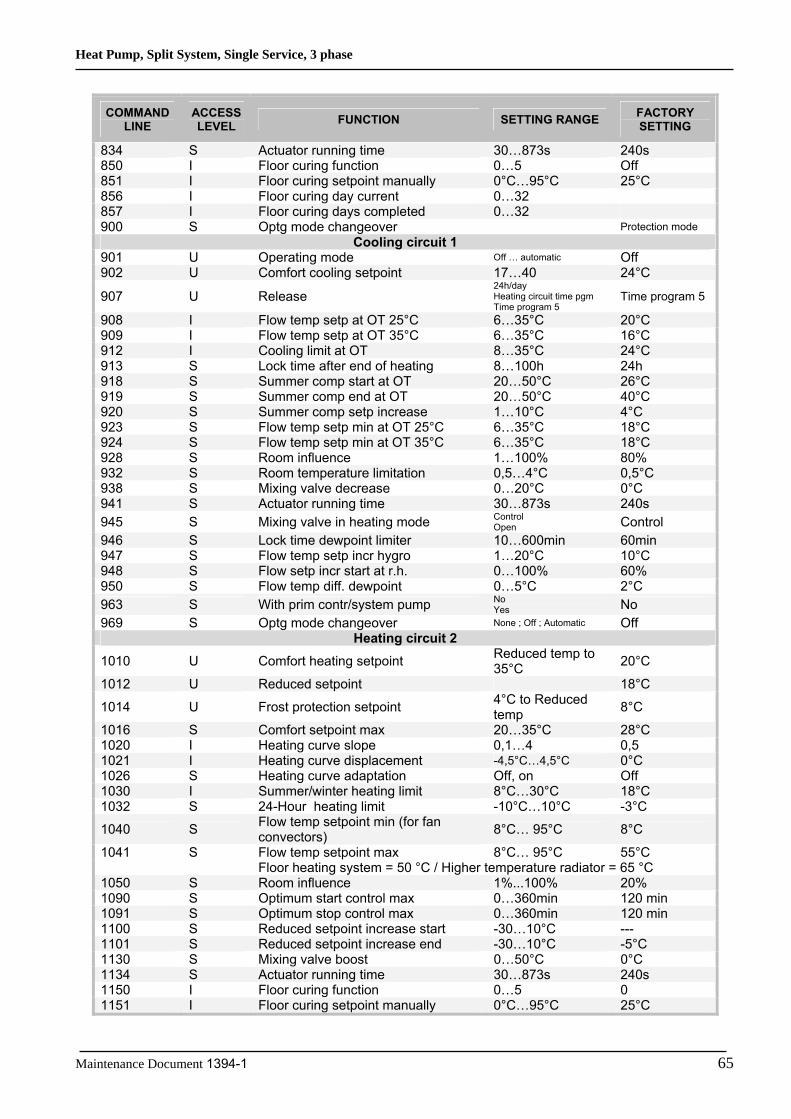
Heat Pump, Split System, Single Service, 3 phase
Maintenance Document 1394-1 65
COMMAND LINE
ACCESS LEVEL FUNCTION SETTING RANGE FACTORY
SETTING
834 S Actuator running time 30…873s 240s 850 I Floor curing function 0…5 Off 851 I Floor curing setpoint manually 0°C…95°C 25°C 856 I Floor curing day current 0…32 857 I Floor curing days completed 0…32 900 S Optg mode changeover Protection mode
Cooling circuit 1 901 U Operating mode Off … automatic Off 902 U Comfort cooling setpoint 17…40 24°C
907 U Release 24h/day Heating circuit time pgm Time program 5
Time program 5
908 I Flow temp setp at OT 25°C 6…35°C 20°C 909 I Flow temp setp at OT 35°C 6…35°C 16°C 912 I Cooling limit at OT 8…35°C 24°C 913 S Lock time after end of heating 8…100h 24h 918 S Summer comp start at OT 20…50°C 26°C 919 S Summer comp end at OT 20…50°C 40°C 920 S Summer comp setp increase 1…10°C 4°C 923 S Flow temp setp min at OT 25°C 6…35°C 18°C 924 S Flow temp setp min at OT 35°C 6…35°C 18°C 928 S Room influence 1…100% 80% 932 S Room temperature limitation 0,5…4°C 0,5°C 938 S Mixing valve decrease 0…20°C 0°C 941 S Actuator running time 30…873s 240s 945 S Mixing valve in heating mode Control
Open Control 946 S Lock time dewpoint limiter 10…600min 60min 947 S Flow temp setp incr hygro 1…20°C 10°C 948 S Flow setp incr start at r.h. 0…100% 60% 950 S Flow temp diff. dewpoint 0…5°C 2°C 963 S With prim contr/system pump No
Yes No 969 S Optg mode changeover None ; Off ; Automatic Off
Heating circuit 2 1010 U Comfort heating setpoint Reduced temp to
35°C 20°C
1012 U Reduced setpoint 18°C
1014 U Frost protection setpoint 4°C to Reduced temp 8°C
1016 S Comfort setpoint max 20…35°C 28°C 1020 I Heating curve slope 0,1…4 0,5 1021 I Heating curve displacement -4,5°C…4,5°C 0°C 1026 S Heating curve adaptation Off, on Off 1030 I Summer/winter heating limit 8°C…30°C 18°C 1032 S 24-Hour heating limit -10°C…10°C -3°C
1040 S Flow temp setpoint min (for fan convectors) 8°C… 95°C 8°C
1041 S Flow temp setpoint max 8°C… 95°C 55°C Floor heating system = 50 °C / Higher temperature radiator = 65 °C 1050 S Room influence 1%...100% 20% 1090 S Optimum start control max 0…360min 120 min 1091 S Optimum stop control max 0…360min 120 min 1100 S Reduced setpoint increase start -30…10°C --- 1101 S Reduced setpoint increase end -30…10°C -5°C 1130 S Mixing valve boost 0…50°C 0°C 1134 S Actuator running time 30…873s 240s 1150 I Floor curing function 0…5 0 1151 I Floor curing setpoint manually 0°C…95°C 25°C

Heat Pump, Split System, Single Service, 3 phase
66 Maintenance Document 1394-1
COMMAND LINE
ACCESS LEVEL FUNCTION SETTING RANGE FACTORY
SETTING
1156 I Floor curing day current 0…32 1157 I Floor curing days completed 0…32 1200 S Optg mode changeover Protection mode
Domestic hot water 1610 U Nominal setpoint Thc…65°C 50°C 1612 U Reduced setpoint 8°C….Thc 25°C
1620 I Release
24h/day Heating circ time pgms Time program 4/DHW Off-peak rate 4: Time pgm 4/DHW or Off-peak rate
Time program 4/DHW
1640 I Legionella function Off Periodic Fixed day in week
Off
1641 I Legionella funct periodically 1 to 7 7 1642 I Legionella funct weekday Mon,…Sun Saturday 1644 I Legionella funct time 00:00…23:50 --:-- 1645 I Legionella funct setpoint 55°C…95°C 65°C 1646 I Legionella funct duration 10min…360min 30 1647 I Legionella funct circ pump On/off On
1660 I Circulation pump release Time program 3/HCP DHW release Time program 4/DHW
DHW release
Swimming pool 2056 U Setpoint source heating 8…80 22
Heat pump 2844 S Switch-off temp max 8°C… 100°C 55°C Floor heating system = 55 °C / Higher temperature radiator = 65 °C 2882 S Release integr electric flow 0… 500°Cmin 100°Cmin 2884 S Release el flow at OT -30°C…30°C 2°C 2910 S Release above OT ---/-30°C…30°C --- 2920 S With electrical utility dock Lock/release Released
Supplementary source 3700 S Release below outside temp -50…50°C 2°C 3705 S Overrun time 0...120min 20 3720 S Switching integral 0… 500°Cmin 100°Cmin
DHW storage tank 5020 S Flow setpoint boost 0…30°C 5°C 5024 S Switching differential 0…20°C 7°C 5030 S Charging time limitation 10…600min 90 min
5060 S El imm heater optg mode Substitution Summer Always Cooling mode
Substitution
5061 S Electric immersion heater release 24h/day DHW release Time program 4/DHW
DHW release
Configuration 5700 I Preselection 1 to 12 1
5711 S Cooling circuit 1 Off 4-pipe system 2-pipe system
Off
5870 S Combi storage tank No/yes No
5987 S Cont type input EX4 Normally-closed contact (NC) Normally-opened contact (NO)
NO
5989 S Cont type input EX5 Normally-closed contact (NC) Normally-opened contact (NO)
NC

Heat Pump, Split System, Single Service, 3 phase
Maintenance Document 1394-1 67
COMMAND LINE
ACCESS LEVEL FUNCTION SETTING RANGE FACTORY
SETTING
6046 I Function Input H2
HC+DHW op mode change HC op mode change HC1 op mode change HC2 op mode change Error/alarm msg Dewpoint monitoring Pool release
Dewpoint monitoring
6047 I Contact type H2 Normally closed Normally open Normally open
6048 S Function value Contact H2 0…130°C 45°C 6100 S Readjustm outside sensor -3…3°C 0°C 6120 S Frost protection for the plant On/off On 6205 S Reset to default parameters No/yes No 6220 S Software version 0…99 0
Errors 6711 U Reset HP No/yes No 6740 S Flow temp 1 alarm 10…240min --- 6741 S Flow temp 2 alarm 10…240min --- 6745 S DHW charging alarm 1…48h --- 6746 S Flow temp cooling 1 alarm 10…240min --- 6800 S History 1 Date/time/code 6802 S History 2 Date/time/code 6804 S History 3 Date/time/code 6806 S History 4 Date/time/code 6808 S History 5 Date/time/code 6810 S History 6 Date/time/code 6812 S History 7 Date/time/code 6814 S History 8 Date/time/code 6816 S History 9 Date/time/code 6818 S History 10 Date/time/code
Service / special operation 7070 S HP interval 1..240 months --- 7071 S HP time since maint 0..240 months 0 7072 S Max starts compr1/hrs run 0,1…12 --- 7073 S Cur starts compr1/hrs run 0…12 0 7076 S Diff condens max/week 1…250 --- 7077 S Cur diff condens max/week 0…250 0 7078 S Diff condens min/week 1…250 --- 7079 S Cur diff condens min/week 0…250 0 7090 S DHW storage tank interval 1…240 --- 7091 S DHW stor tank since maint 0…240 0 7141 U Emergency operation On/off Off 7142 S Emergency operation function type Manual/auto Manual 7150 I Simulation outside temp -50…50°C --- 7181 I Phone no. responsibility 1 0…255 7183 I Phone no. responsibility 2 0…255
Input / output test
7700 I Relay test
No test All OFF Relay output QX23 module 1 Relay output QX21 module 1 Relay output QX22 module 1 Relay output QX1 Relay output QX2 Relay output QX3 Relay output QX4 Relay output QX5 Relay output QX6 Relay output QX23 module 2 Relay output QX21 module 2 Relay output QX22 module 2 Relay output QX7
No test
7710 I Output test UX 0…100% ---%

Heat Pump, Split System, Single Service, 3 phase
68 Maintenance Document 1394-1
COMMAND LINE
ACCESS LEVEL FUNCTION SETTING RANGE FACTORY
SETTING
7711 I Voltage signal UX 0…10volt 0 volt
7720 I Digital output test No test All OFF Digital output DO1 Digital output DO2
No test
7721 I Digital output DO1 Cooling mode Heating mode Heating mode
7722 I Digital output DO2 On/off Off 7730 I Outside temp B9 -50…50°C 0°C 7820 I Sensor temp BX1 -28…350°C 0°C 7823 I Sensor temp BX4 -28…350°C 0°C 7824 I Sensor temp BX5 -28…350°C 0°C 7830 I Sensor temp BX21 module 1 -28…350°C 0°C 7831 I Sensor temp BX22 module 1 -28…350°C 0°C 7832 I Sensor temp BX21 module 2 -28…350°C 0°C 7833 I Sensor temp BX22 module 2 -28…350°C 0°C 7841 I Contact state H1 Open/closed Open 7846 I Contact state H2 Open/closed Open 7855 I Contact state H3 Open/closed Open 7914 I Input Ex4 0/230V 0 7915 I Input Ex5 0/230V 0 7916 I Input Ex6 0/230V 0
State of plant 8000 I State heating circuit 1 0 8001 I State heating circuit 2 0 8003 I State DHW 0 8004 I State cooling circuit 1 0 8006 I State heat pump 0 8011 I State swimming pool 0 8022 I State supplementary source 0 8050 I History 1 Date/time/code 8052 I History 2 Date/time/code 8054 I History 3 Date/time/code 8056 I History 4 Date/time/code 8058 I History 5 Date/time/code 8060 I History 6 Date/time/code 8062 I History 7 Date/time/code 8064 I History 8 Date/time/code 8066 I History 9 Date/time/code 8068 I History 10 Date/time/code
Diagnostics heat source 8402 I El imm heater 1 flow Off/on Off 8403 I El imm heater 2 flow Off/on Off 8406 I Condenser pump Off/on Off 8410 U Return temp HP 0…140°C 0°C 8411 U Setpoint HP 0…140°C 0°C 8412 U Flow temp HP 0…140°C 0°C 8413 U Compressor modulation 0…100% 0% 8425 I Temp diff condenser -50…140°C 0°C 8454 S Locking time HP 0…2730h 00:00:00 8455 S Counter number of locks HP 0…65535 0 8456 S Hours run el flow 0…2730h 00:00:00 8457 S Start counter el flow 0…65535 0
Diagnostics consumers 8700 U Outside temperature -50…50°C 0°C 8701 U Outside temp min -50…50°C 50°C 8702 U Outside temp max -50…50°C -50°C 8703 I Outside temp attenuated -50…50°C 0°C 8704 I Outside temperature composite -50…50°C 0°C
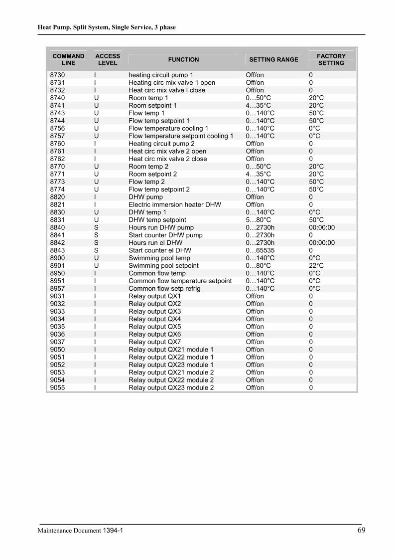
Heat Pump, Split System, Single Service, 3 phase
Maintenance Document 1394-1 96
COMMAND LINE
ACCESS LEVEL FUNCTION SETTING RANGE FACTORY
SETTING
8730 I heating circuit pump 1 Off/on 08731 I Heating circ mix valve 1 open Off/on 0 8732 I Heat circ mix valve I close Off/on 0
C°02 C°05…0 1 pmet mooR U 04788741 U Room setpoint 1 4…35°C 20°C
C°05 C°041…0 1 pmet wolF U 34788744 U Flow temp setpoint 1 0…140°C 50°C 8756 U Flow temperature cooling 1 0…140°C 0°C 8757 U Flow temperature setpoint cooling 1 0…140°C 0°C8760 I Heating circuit pump 2 Off/on 0 8761 I Heat circ mix valve 2 open Off/on 08762 I Heat circ mix valve 2 close Off/on 0 8770 U Room temp 2 0…50°C 20°C 8771 U C°02 C°53…4 2 tnioptes mooR8773 U Flow temp 2 0…140°C 50°C 8774 U Flow temp setpoint 2 0…140°C 50°C 8820 I DHW pump Off/on 08821 I Electric immersion heater DHW Off/on 0 8830 U DHW temp 1 0…140°C 0°C8831 U DHW temp setpoint 5…80°C 50°C 8840 S Hours run DHW pump 0…2730h 00:00:008841 S Start counter DHW pump 0…2730h 0 8842 S Hours run el DHW 0…2730h 00:00:008843 S Start counter el DHW 0…65535 0 8900 U Swimming pool temp 0…140°C 0°C8901 U Swimming pool setpoint 0…80°C 22°C 8950 I Common flow temp 0…140°C 0°C8951 I Common flow temperature setpoint 0…140°C 0°C 8957 I Common flow setp refrig 0…140°C 0°C9031 I Relay output QX1 Off/on 09032 I Relay output QX2 Off/on 09033 I Relay output QX3 Off/on 09034 I Relay output QX4 Off/on 09035 I Relay output QX5 Off/on 09036 I Relay output QX6 Off/on 09037 I Relay output QX7 Off/on 09050 I Relay output QX21 module 1 Off/on 09051 I Relay output QX22 module 1 Off/on 09052 I Relay output QX23 module 1 Off/on 09053 I Relay output QX21 module 2 Off/on 09054 I Relay output QX22 module 2 Off/on 09055 I Relay output QX23 module 2 Off/on 0

Heat Pump, Split System, Single Service, 3 phase
70 tnemucoD ecnanetniaM 1394-1
6 End of summertime
NOTE: Summer time/winter time change Dates have been set for changing to summer time or to winter time. The time changes automatically from 2am (winter time) to 3am (summer time) or from 3am (summer time) to 2am (winter time) on the first Sunday following the respective date.
6.3 Adjustment Function Details
6.3.1 Date and Time Functions The controller has an annual clock which contains the time, the day of the week and the date.
In order for the function to operate, the time and date must be set properly on the clock.
LINE NO. PROGRAMMING LINE 1 Hour/minutes 2 Day/month3 Year 5 Start of summertime

Heat Pump, Split System, Single Service, 3 phase
Maintenance Document 1394-1 71
6.3.2 User Interface Functions LINE NO. PROGRAMMING LINE 20 Language 22 Info 26 Operation lock 27 Programming lock 28 Direct adjustment
Info (22): • Temporary: After pressing the Info key, the information display returns to the basic "predefined" display after 8 minutes or when pressing the operating mode key. • Permanent: After pressing the Info key, the information display returns to the "new" standard display after a maximum of 8 minutes. The last selected information value is shown in the new basic display.
Operation lock (26): If the operating lock is activated, the following control elements can no longer be adjusted: Heating circuit mode, DHW mode, room temp comfort setpoint (knob), occupancy key.
Programming lock (27): If the programming lock is activated, the setting values are displayed but may no longer be changed.
• Temporary Suspension of Programming The programming lock can be temporarily deactivated at programming level. To do this, simultaneously press the OK and ESC keys for at least 3 seconds. The temporary suspension of the programming lock remains in effect until you exit the programming. • Permanent Suspension of Programming First perform a temporary suspension, then cancel "Programming lock" on line 27.
Direct adjustment (28): • Automatic Save Correction of the setpoint with the knob is adopted without a particular confirmation (timeout) or by pressing the OK key. • Confirm save Correction of the setpoint with the knob will be adopted only after pressing the OK key.
Used as (40):
LINE NO. PROGRAMMING LINE
40* Used as (Room unit 1 / Room unit 2 / Room unit P / Operator unit1 ¦ Operator unit 2 ¦ Operator unit P ¦ Service unit)
* applies only to room central units C75 This line allows adjusting the use of the user interface. According to use, other settings will be required under "Heating circuit assignment". If several user interfaces are used, operation of each device can be defined selectively. o If several user interfaces are used, each device address may be used only once. o The user interface mounted to the Hydraulic Units is set in the factory as operating device 1 (line 40) which has an effect on all heating circuits (line 42) and can be configured only on command lines 44, 46, 48.
Depending on how the device is used (line 40), the following adjustments can be made for assignment to the heating circuits with the following effects:

Heat Pump, Split System, Single Service, 3 phase
72 Maintenance Document 1394-1
Programming line
40 42 44 46 48 54 Room unit 1 Heating circuit 1 X Heating circuits 1 and 2 X X X Heating circuits 1 and P X X X All HCs Room unit 2 Room unit P Operator unit 1 Heating circuit 1 Heating circuits 1 and 2 X X Heating circuits 1 and P X X All HCs X X X Operator unit 2 Operator unit P Operating unit
• Room unit 1 The user interface controls the heating circuits which are authorized on line 42 "Room unit 1 assignment" and which have been activated accordingly in the base unit. • Room unit 2 The user interface only controls heating circuit 2.
• User interface / operating unit The user interface controls the heating circuits that have been activated in the base unit. Note: with this setting, no room temperature is saved or transmitted by the user interface.
Heating Circuit Assignment
LINE NO. PROGRAMMING LINE 42* Assignment device 1 44 Operation HC2 46 Operation HCP 48* Operator occupancy button 54* Readjustment room sensor 70 Software version
* applies only to room central units C75
Unit 1 assignment As unit 1 (setting 40), action of the respective user interface can be assigned either to heating circuit 1 or to both heating circuits. The second option is necessary particularly when there are 2 heating circuits and only one room unit.
Operation HC2 Depending on the setting of line 40, the operating action (operating mode key or knob) can be defined either on room unit 1, on the user interface or on the operating unit for heating circuit 2. • Commonly with HC1 The control for heating circuits 1 and 2 is shared. • Independently Action of the control is called on the display whenever use is made of the operating key or the knob.
Operation HCP According to command line 40, the control action (operating mode key or knob) can be defined either on room unit 1, on the user interface, or on the operating unit for heating circuit P. • Commonly with HC1 The control for heating circuits 1 and 2 is shared. • Independently Changes in the operating mode or adjustment of the nominal temperature setpoint must be made in the programming.
Readjustment room sensor The room sensor indication can be corrected.
Software version The indication shows the current version of the user interface.

Heat Pump, Split System, Single Service, 3 phase
Maintenance Document 1394-1 73
6.3.3 Time Program Functions (heating circuit 1 & 2, DHW, cooling) Several control programs are available for the heating circuits and the production of DHW. They are initiated in "Automatic" mode and control the change in temperature levels (and therefore the associated setpoints, reduced and comfort) via the adjusted changeover times.
Enter changeover times: Changeover times can be adjusted in a combined way, i.e., identical times for several days or distinct times for certain days. Preselecting groups of days (e.g., Mon...Fri and Sat...Sun) having the same changeover times makes adjustment of the changeover program considerably shorter.
Changeover Points Line no. HC1 HC2 4/DHW 5
Programming line
500 520 560 600 Preselection (Mon-Sun / Mon-Fri / Sat – Sun / Mon...Sun)
501 521 561 601 1st phase On 502 522 562 602 1st phase Off 503 523 563 603 2nd phase On 504 524 564 604 2nd phase Off 505 525 565 605 3rd phase On 506 526 566 606 3rd phase Off
Standard Program Line no. Programming line 516, 536, 576, 616 Default values
(No /Yes)
All time programs can be reset to factory settings. Each time program has its own command line for this reset action.
In this case, individual settings will be lost!
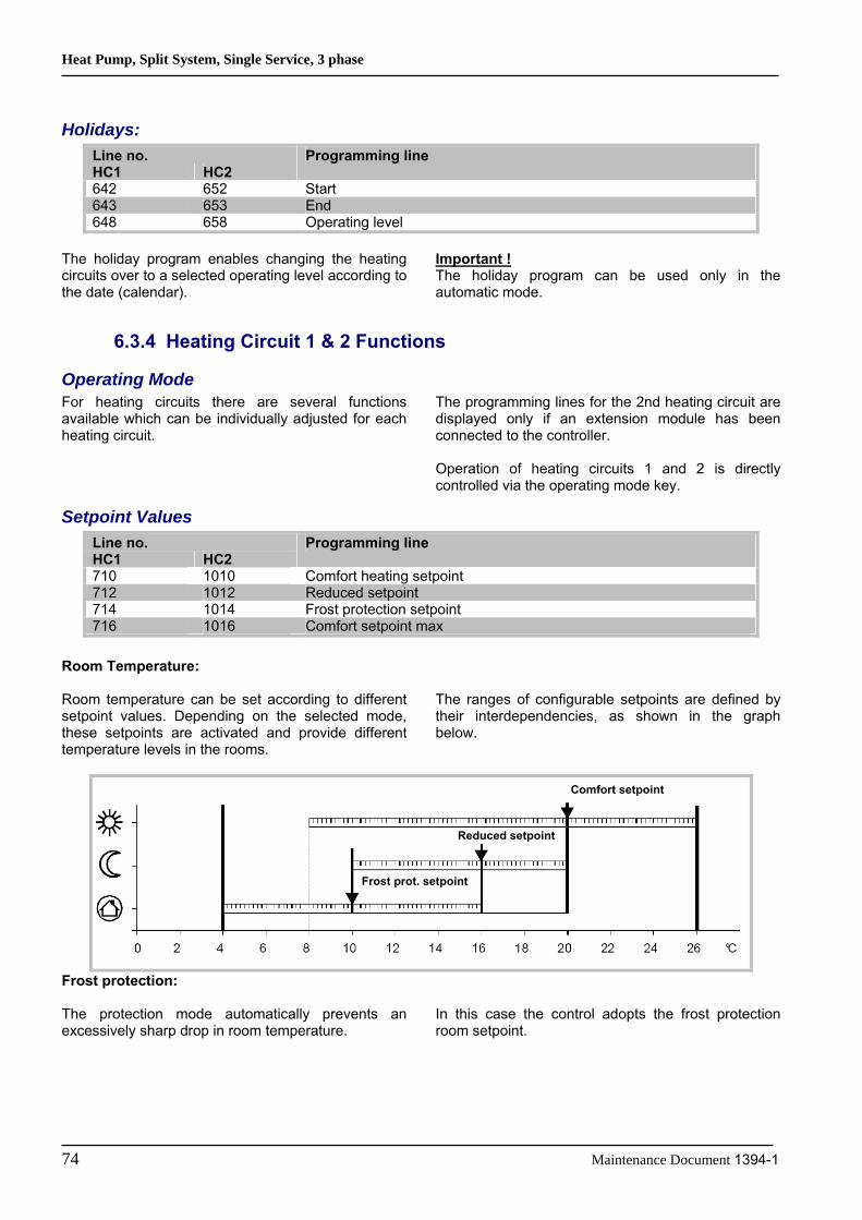
Heat Pump, Split System, Single Service, 3 phase
74 Maintenance Document 1394-1
Holidays: Line no. HC1 HC2
Programming line
642 652 Start 643 653 End 648 658 Operating level
The holiday program enables changing the heating circuits over to a selected operating level according to the date (calendar).
Important ! The holiday program can be used only in the automatic mode.
6.3.4 Heating Circuit 1 & 2 Functions
Operating Mode For heating circuits there are several functions available which can be individually adjusted for each heating circuit.
The programming lines for the 2nd heating circuit are displayed only if an extension module has been connected to the controller. Operation of heating circuits 1 and 2 is directly controlled via the operating mode key.
Setpoint Values Line no. HC1 HC2
Programming line
710 1010 Comfort heating setpoint 712 1012 Reduced setpoint 714 1014 Frost protection setpoint 716 1016 Comfort setpoint max
Room Temperature: Room temperature can be set according to different setpoint values. Depending on the selected mode, these setpoints are activated and provide different temperature levels in the rooms.
The ranges of configurable setpoints are defined by their interdependencies, as shown in the graph below.
Frost protection: The protection mode automatically prevents an excessively sharp drop in room temperature.
In this case the control adopts the frost protection room setpoint.
Comfort setpoint
Reduced setpoint
Frost prot. setpoint

Heat Pump, Split System, Single Service, 3 phase
Maintenance Document 1394-1 75
Heating Curve Line no. HC1 HC2
Programming line
720 1020 Heating curve slope 721 1021 Heating curve displacement 726 1026 Heating curve adaptation
Heating curve slope: Based on the heating characteristic, the controller computes the flow temperature setpoint which will be used for controlling the flow temperature in consideration of atmospheric conditions. Different settings can be used to adapt the heating characteristic so that the heating capacity, and therefore the room temperature, will match the individual needs. The colder the outdoor temperature, the greater the extent to which the slope will modify the flow temperature. In other words, the slope should be corrected if the room temperature shows a difference when the outdoor temperature is low, but not when it is high.
o Increase the setting: The flow temperature is increased mainly when the outdoor temperatures are low. o Decrease the setting: The flow temperature is lowered mainly when the outdoor temperatures are low. Warning: The heating curve is adjusted in relation to a room temperature setpoint of 20°C. If the room temperature setpoint is modified, the flow temperature setpoint is automatically recomputed. This will not modify the setting and amounts to automatically adapting the curve.
20
30
40
50
60
70
-20,0-15,0-10,0-5,00,05,010,015,020,0
Outdoor Temperature (°C)
Hea
ting
Flow
Tem
pera
ture
(°C
)
0,25
0,5
0,75
1
1,25
1,5
1,752
Heating Curves

Heat Pump, Split System, Single Service, 3 phase
76 Maintenance Document 1394-1
Heating curve displacement The curve shift (offset) modifies the flow temperature in a general and even manner over the full range of outdoor temperature. In other words, the shift should be corrected when the room temperature is generally too high or too low.
Heating curve adaptation Adaptation enables the controller to automatically adapt the heating curve to the present conditions. This correction may only be activated or deactivated. In the latter case, there is no need to correct the slope and shift.
Information: To ensure operation, the following requirements must be met: - A room sensor must be connected. - The "room influence" parameter must be set between 1 and 99. - The reference room (where the room sensor is installed) must not contain adjusted thermostatic valves. If present in the room, these valves must be fully open. - Operation of this function requires an adaptation period which can take more or less time (approx. 1 week) depending on weather conditions and on the stability of the room temperature setpoint.
Eco Functions Line no. HC1 HC2
Programming line
730 1030 Summer/winter heating limit 732 1032 24-Hour heating limit
Summer/winter heating limit The summer/winter heating limit switches the heating on or off through the year according to the temperature ratio. Changeover is performed automatically when in automatic mode and thus avoids the user having to turn the heating on or off. Changing the input value makes the respective annual periods (summer/winter) shorter or longer. - If the value is increased: Changing to winter operating mode is advanced, changing to summer mode is delayed - If the value is decreased: Changing to winter mode is delayed; changing to summer mode is advanced.
Information: This function does not work in "Continuous Comfort temperature" mode. (Sunlight) The controller displays "ECO". The outdoor temperature is attenuated to take the building's dynamics into account.
Example:
Sum/win heating limit + 1°C Sum/win heating limit Sum/win heating limit - 1°C
Attenuated outdoor T
Days

Heat Pump, Split System, Single Service, 3 phase
Maintenance Document 1394-1 77
24-Hour heating limit The 24-hour heating limit is used to switch the heating on and of in the course of the day, depending on the outside temperature.This function is used mainly during intermediate seasons (spring and fall) to react rapidly in case of fluctuating temperatures.
Thus, in the following example the changeover temperature will be 18°C, computed as follows:
Comfort heating setpoint (710) 22°C 24-Hour heating limit (732) -3°C Changeover temperature (710 – 732) Heating off
=19°C
Differential (Fixed) -1°C Changeover temperature Heating on =18°C
Changing the input value makes the respective heating periods shorter or longer. - If the value is increased: changeover to heating mode is advanced; changeover to ECO is delayed. - If the value is decreased: changeover to heating mode is delayed; changeover to ECO is advanced.
Information: This function will not work in "Continuous Comfort temperature" mode. The display will show "ECO". The outdoor temperature is attenuated to take the building's thermal dynamics into account.
Flow temperature setpoint Line no. HC1 HC2
Programming line
740 1040 Flow temp setpoint min (for fan convectors) 741 1041 Flow temp setpoint max
This limitation allows to define a range for the orders to start. When instructed to start the heating circuit reaches the threshold, this record remains
permanently at the maximum or minimum, even if the heat demand continues to increase or decrease.
Room Influence Line no. HC1 HC2
Programming line
750 1050 Room influence Control types: When using a room temperature sensor there are 3 different types of control to choose from.
SETTING CONTROL TYPE - - - % Simple control according to outdoor conditions * 1...99 % Control according to outdoor conditions with room influence * 100 % Control according to room temperature only
* Requires the connection of an outdoor sensor
Simple control according to outdoor conditions The flow temperature is computed via the heating curve according to the averaged outdoor temperature. This type of control requires proper adjustment of the heating curve, as the control does not take the room temperature into account for this adjustment.
Control according to outdoor conditions with room influence The difference between the room temperature and the setpoint value is measured and taken into account for temperature control. This enables taking into account possible heat inputs and ensures a more even room temperature.

Heat Pump, Split System, Single Service, 3 phase
78 Maintenance Document 1394-1
The influence of the difference is defined as a percentage. The better the installation in the reference room (accurate room temperature, correct installation location, etc.) the higher will be the value that can be set. Example: Approx 60%: the reference room is appropriate Approx 20 %: the reference room is inappropriate Information: Activation of the function requires taking into account the following requirements: - A room sensor must be connected. - The "room influence" parameter must be set between 1 and 99. - The reference room (where the room sensor is installed) must not contain adjusted thermostatic valves. If present in the room, these valves must be fully open.
Control according to room temperature only The flow temperature is adjusted according to the room temperature setpoint, the current room temperature and its evolution. A slight increase in room temperature, for example, causes an immediate drop in the flow temperature. Information: Activation of the function requires taking into account the following requirements: - A room sensor must be connected. - The "room influence" parameter must be set to 100%. The reference room (where the room sensor is installed) must not contain adjusted thermostatic valves. If present in the room, these valves must be fully open.

Heat Pump, Split System, Single Service, 3 phase
Maintenance Document 1394-1 79
Optimisation at switch-on and switch-off Line no. HC1 HC2
Programming line
790 1090 Optimum start control max 791 1091 Optimum stop control max
Optimum start control max The change in temperature levels is optimised in such a way as to reach the comfort setpoint during changeover times.
Optimum stop control max The change in temperature levels is optimised in such a way as to reach the comfort setpoint -1/4 °C during changeover times.
Reduced Setpoint Increase Line no. HC1 HC2
Programming line
800 1100 Reduced setpoint increase start 801 1101 Reduced setpoint increase end
This function is used mainly in heating installations that do not have high supplies of power (e.g. low energy homes). In that case, when outdoor temperatures are low, adjusting the temperature would be too long.
Increasing the reduced setpoint prevents excessive cooling of the rooms in order to shorten the temperature adjustment period when changing over to the comfort setpoint.
Comfort setpoint(710)
Reduced setpoint(712)
Begin increase(800)
End increase (801)
Averaged OT

Heat Pump, Split System, Single Service, 3 phase
80 Maintenance Document 1394-1
Mixing Valve Control Line no. HC1 HC2
Programming line
830 1130 Mixing valve boost 834 1134 Actuator running time
Mixing valve boost The controller adds the increase set here to the current flow setpoint and uses the result as the temperature setpoint for the heat generator.
Actuator running time For 3-position control the valve servomotor travel time can be adjusted. With a 2-position servomotor, the adjusted travel time is inoperative.
Controlled floor drying function Line no. HC1 HC2
Programming line
850 1150 Floor curing function 851 1151 Floor curing setpoint manually 856 1156 Floor curing day current 857 1157 Floor curing days completed
This function is used in the controlled drying of floors. It adjusts the flow temperature to a temperature profile. Drying is performed by floor heating via the heating circuit with a mixing valve or with a pump.
"Controlled floor curing" function • Off: The function is deactivated. • Heating operational (Fh): The first part of the temperature profile is automatically completed. • Heating "ready for occupancy" (Bh) The second part of the temperature profile is handled automatically.. • Heating "ready for occupancy" / Heating operational The full temperature profile (1st and 2nd part) is performed automatically. • Manual No temperature profile is performed, but the control is performed according to the "manual controlled drying setpoint". The function is automatically terminated after 25 days Important o The standards and directions of the building contractor must be followed! o This function will not work properly unless the installation has been adequately made (hydraulics, electricity, settings). Otherwise, the floors to be dried may be damaged! o The function may be prematurely interrupted by setting it to Off.
o The maximum flow temperature limitation remains active.

Heat Pump, Split System, Single Service, 3 phase
Maintenance Document 1394-1 81
"Manual controlled curing" setpoint The flow temperature setpoint for the "Manual" controlled floor drying function can be adjusted separately for each heating circuit.
Current controlled curing setpoint Displays the current flow temperature setpoint for the controlled floor drying function
Current day of controlled curing Displays the current day of the controlled floor drying function Important: After a power outage, the installation resumes the controlled drying function as it was when the outage occurred.
Operating Mode Changeover Line no. HC1 HC2
Programming line
900 1200 Optg mode changeover (None / Frost protection mode / Reduced / Comfort / Automatic)
In case of an external changeover via input H2 (on the extension module only) the operating mode to which the changeover will be performed must be previously defined.
Heating Circuit Frost Protection The heating circuit frost protection is continuously activated (protection mode ) and is not adjustable.
Heating circuit frost protection in heating mode If the flow temperature is below 5°C, the controller initiates the production of heat and starts the heating pumps, regardless of the current heating mode.
If the flow temperature rises again above 7°C, the controller waits another 5 minutes, and then stops the production of heat and the heating pumps.
Heating circuit frost protection in cooling mode See Cooling mode
Days
Heat pump flow temp
Fh Bh
X : Starting day Fh + Bh

Heat Pump, Split System, Single Service, 3 phase
82 Maintenance Document 1394-1
6.3.5 Cooling Circuit 1 Functions The cooling sequence is automatically started when the room temperature is higher than the comfort setpoint in cooling mode (line 902). The cooling function must be activated (command line 901 = Auto) and is triggered by the programming clock (Command line 907). The cooling sequence is interrupted as soon as heating circuit 1 indicates a need for heat or in the presence of a heat demand signal from a DHW circuit or other heating circuit (only if cooling is active). The controller measures the current room temperature and compares it with the room temperature setpoint to compute the flow temperature setpoint. If the temperature is not low enough the heat pump is started to provide cooling (reversed control of the mixing valve).
The following settings apply to the hydraulic circuit in zone 1 (HC1). If there is a second zone, this zone can be cooled with the setting 963 which will connect the pump directly to zone 2. This will require setting the "Mixing valve sub-cooling" parameter (938) to a suitable value in order for both zones to be adequately cooled according to the available emitters. WARNING: Cooling mode is prohibited on all radiators, heating-only floors, or any emitters not intended for this purpose.
Operating Mode Line no. Programming line 901 Operating mode
(Off / Automatic)
The cooling key on the user interface enables switching between operating modes. • Off: The cooling function is deactivated.
• Automatic: The cooling function is automatically activated by the time program (command line 907), the holiday program, the occupancy key, or according to the need.
Comfort cooling setpoint Line no. Programming line 902 Comfort cooling setpoint
In cooling mode the room temperature control follows the comfort setpoint adjusted under this setting. The cooling comfort setpoint can be displayed with a knob on the room unit.
In summer the comfort setpoint is gradually increased in relation to the outdoor temperature (see lines 918-920).
Release: Line no. Programming line 907 Release
(24h/day / heating circuit time pgm / Time program 5)
The "Release" setting determines the time program according to which cooling is released. • 24h/day: Cooling is continuously activated (24h/day).
• heating circuit time program: Cooling is activated according to the heating circuit time program. • Time program 5: Cooling is released according to time program 5.

Heat Pump, Split System, Single Service, 3 phase
Maintenance Document 1394-1 83
Cooling Characteristic Line no. Programming line 908 Flow temp setp at OT 25°C 909 Flow temp setp at OT 35°C
The controller computes the flow temperature required for a given averaged outdoor temperature based on the cooling characteristic. This is defined by two reference points (flow setpoint at 25°C and at 35°C).
Flow temp setp at OT 25°C This is the cooling flow temperature required when the averaged outdoor temperature is 25°C, without summer compensation.
Flow temp setp at OT 35°C This is the cooling flow temperature required when the averaged outdoor temperature is 35°C, without summer compensation.
The cooling characteristic is adjusted for a 25°C room temperature setpoint. If the room temperature setpoint is changed the curve will automatically adapt.
Eco Line no. Programming line 912 Cooling limit at OT 913 Lock time after end of heating
Cooling limit at OT If the composite outdoor temperature is higher than the cooling limit, cooling is released. If the composite outdoor temperature falls at least 0.5°C below the cooling limit, cooling is locked.
Lock time after end of heating To avoid a quick start of cooling after termination of heating, the cooling function is locked for a time period which can be adjusted with this setting. The lock time starts when there is no valid heating demand from heating circuit 1. Heating demands from heating circuits 2 or P are ignored. Information: Switching off and switching on again the mode selection key causes the lock time to be interrupted
25°C 35°C
909
908
Averaged OT
Flow temp setpoint

Heat Pump, Split System, Single Service, 3 phase
84 Maintenance Document 1394-1
Summer Compensation Line no. Programming line 918 Summer comp start at OT 919 Summer comp end at OT 920 Summer comp setp increase
In summer the "cooling comfort setpoint" (902) is gradually increased according to the outdoor temperature. This saves on cooling power and prevents the differences between the ambient temperature of the room and the outdoor temperature being too high. The resulting "room temperature setpoint" (cooling) can be viewed in the Info section.
Summer compensation start at OT Summer compensation starts to be active from the outdoor temperature defined here. If the outdoor temperature continues to rise, the comfort setpoint will be gradually increased.
Summer compensation end at OT At this outdoor temperature the summer compensation reaches its peak efficiency (920). If the outdoor temperature continues to rise, it will no longer influence the comfort setpoint.
Summer compensation setpoint increase This setting defines the highest value to which the comfort setpoint can be increased.
918 919
902
920
OT
Comfort setpoint

Heat Pump, Split System, Single Service, 3 phase
Maintenance Document 1394-1 85
Flow Setpoint Limitation Line no. Programming line 923 Flow temp setp min at OT 25°C 924 Flow temp setp min at OT 35°C
It is possible to assign a lower limit to the cooling flow temperature. The limitation line will be defined by two reference points. In addition the resulting flow setpoint will have a lower limit and may not be less than 5 °C.
Flow temp setp min at OT 25°C Determines the lowest flow temperature for a composite outdoor temperature of 25°C.
Flow temp setp min at OT 35°C Determines the lowest flow temperature for a composite outdoor temperature of 35°C. Warning: If no outdoor temperature is available, the controller will use the "Min. flow setpoint at OT= 35°C" parameter.
Room Influence Line no. Programming line 928 Room influence
When using a room temperature sensor there are 3 different types of control to choose from.
SETTING CONTROL TYPE - - - % Simple control according to outdoor conditions * 1...99 % Control according to outdoor conditions with room influence * 100 % Control according to room temperature only
* Requires the connection of an outdoor sensor
Simple control according to outdoor conditions The flow temperature is obtained from the composite outdoor temperature on the basis of the cooling characteristic.
This type of control requires the cooling curve to be properly adjusted, as the control does not take the room temperature into account for this adjustment.
25°C 35°C
924
923
Averaged OT
Flow temp setpoint
Flow temp setpoint

Heat Pump, Split System, Single Service, 3 phase
86 Maintenance Document 1394-1
Control according to outdoor conditions with room influence The difference between the room temperature and the setpoint value is measured and taken into account for temperature control. This enables taking into account possible heat inputs and ensures a more even room temperature. Thus the differences with the room temperature are taken into account and the room temperature becomes more stable. The influence of the difference is defined as a percentage. The better the installation in the reference room (accurate room temperature, correct installation location, etc.) the higher will be the value that can be set. Example: • Approx 60%: the reference room is appropriate • Approx 20 %: the reference room is inappropriate Activation of the function requires taking into account the following requirements: • A room sensor must imperatively be connected. • The "room influence" parameter must be set between 1 and 99. • The reference room (where the room sensor is installed) must not contain adjusted thermostatic valves. Any thermostatic valves present in the rooms must be fully open.
Control according to room temperature only The flow temperature is adjusted according to the room temperature setpoint, the current room temperature and its evolution. A slight increase in room temperature, for example, causes an immediate drop in the flow temperature. Activation of the function requires taking into account the following requirements: • A room sensor must imperatively be connected. • The "room influence" parameter must be set to 100%. • The reference room (where the room sensor is installed) must not contain adjusted thermostatic valves. Any thermostatic valves present in the rooms must be fully open.
Room Temperature Limitation Line no. Programming line 932 Room temperature limitation
The "room temperature limitation" function enables shutting off the cooling circuit pump if the room temperature falls below the adjusted room temperature setpoint (with summer compensation line 920) by more than the adjusted differential. The cooling circuit pump is reinitiated as soon as the room temperature rises again above the current room temperature setpoint.
If the room temperature limitation function is active, no cooling demand will be transmitted to production. The function is deactivated if: • no room temperature sensor is available • "Room influence limit." = --- • "Room influence" (928) = --- (simple control according to outdoor conditions)

Heat Pump, Split System, Single Service, 3 phase
Maintenance Document 1394-1 87
Mixing Valve Control Line no. Programming line 938 Mixing valve cooling offset 941 Actuator running time 945 Mixing valve in heating mode
Mixing valve cooling offset The cooling demand issued by cooling circuit 1 to production is reduced by the adjusted value.
If there is a second zone, this reduction should enable the second zone to be cooled. To achieve this result, the sub-cooling must be determined in accordance with the type of emitter and the parameter 963 "With prim control/prim pump" must be set to "yes" to switch on the pump for the second zone.
Example:
Configuration How the configuration affects control Zone 1: Heating/cooling floor Zone 2: Fan coils
938 = 10°C, with 924 = 18°C 963 = yes
with a 35°C outdoor temperature the flow setpoint will be 18°C – 10°C i.e. 8°C while in the first zone (HCF) it will be 18°C through action of the mixing valve
Zone 1: Heating/cooling floor Zone 2: HCF
938 = 0°C, with 924 = 18°C 963 = yes
with a 35°C outdoor temperature the flow setpoint will be 18°C in both zones
WARNING: If these settings are not chosen properly the heat pump may stop automatically due to the flow temperature being too low. A safety mechanism is triggered at 6°C to protect the exchanger from freezing.
Actuator running time For the 3-position servomotor used, it is possible to adjust the travel time. With a 2-position servomotor, the adjusted travel time is inoperative.
Mixing valve in heating mode Determines the position of mixing valve 1 (Y1 / Y2) during heating operation is activated.
This parameter is inoperative in installations where heating and cooling circuits are hydraulically separate. Control: the valve controls in heating and cooling mode. Open: the valve controls in cooling mode, and is open in heating mode.

Heat Pump, Split System, Single Service, 3 phase
88 Maintenance Document 1394-1
Dewpoint Monitoring Line no. Programming line 946 Lock time dewpoint limiter 947 Flow temp setp incr hygro 948 Flow setp incr start at r.h. 950 Flow temp diff. dewpoint
These settings are useful only when a dewpoint sensor (hygrostat). is used.
Lock time dewpoint limiter As soon as the dewpoint sensor detects condensation, it closes its contact and switches off the cooling process. When the contact reopens the "dewpoint sensor lock time" period begins. Cooling will resume only after this time period has elapsed. The dewpoint sensor must be assigned to input H2 as "Dewpoint sensor".
Flow temp setp incr hygro To avoid condensation due to an excessively high humidity level in the room, a fixed increase in flow temperature can be obtained by means of a hygrostat. As soon as the humidity exceeds the value set on the hygrostat, the hygrostat closes its contact and activates the flow temperature increase defined here.
The hygrostat must be assigned to an Hx input as "Flow temp setpoint increase by hygrostat".
Flow setp incr start at r.h. To avoid condensation caused by an excessively high humidity level in the room, a gradual increase in flow temperature can be performed by means of a humidity measurement 0... 10 V. If the room's relative humidity exceeds the value "Beginning of flow temp increase at relative humidity", the flow setpoint is gradually increased. The increase beginning (line 948) and the maximum increase (line 947) can be adjusted. The humidity sensor must be assigned to an H2 input as "room relative humidity 10V".
Flow temp diff. dewpoint The relative humidity of the ambient air and the corresponding room temperature are used to compute the dewpoint temperature. To prevent condensation forming on the surfaces, the value adjustable on line 950 determines the lower limit of the flow temperature above the dewpoint temperature.
This function can be deactivated with the setting - - - . The humidity sensor must be assigned to an H2 input as "Room relative humid. 10V" and a room temperature sensor is required (input H2 as "Room temperature 10V" or "room unit").
948 100%
947
Relative humidity
Flow temp setpoint increase

Heat Pump, Split System, Single Service, 3 phase
Maintenance Document 1394-1 89
With prim controller/system pump Line no. Programming line 963 With prim contr/system pump
(no / yes)
This setting specifies whether the cooling circuit is supplied from the primary controller or from the primary pump (depending on the installation). It can also be used to provide cooling to the second zone.
Warning: In the case of a radiator or any other emitter which does not support the cooling mode in zone 2, this setting must remain on "No".
Optg mode changeover Line no. Programming line 969 Optg mode changeover
(none / Off / Automatic)
In case of an external change via inputs H2 the operating mode to which the changeover will be performed must be previously defined
6.3.6 DHW Functions The control sets the DHW temperature, according to the time program or continuously, to the desired setpoint. The priority of DHW charging over room heating is adjustable in this case.
The controller has a configurable legionella function designed for protection against legionella in the storage tank and the pipes. The circulation pump is controlled according to the current time program and operating mode.
Setpoint value Line no. Programming line 1610 Nominal setpoint 1612 Reduced setpoint
The DHW is heated to various setpoint values. These setpoints are active according to the selected
operating mode and allow the desired temperatures to be reached in the DHW storage tank.
Important: For optimal operation we recommend reducing the setpoints to the lowest value. Setpoints which are too high may interfere with heating and cause some discomfort. In this case DHW/Heating changeover cycles may successively occur.
If DHW charge boosting is not desired during the day, we recommend adjusting the reduced temperature setpoint to 15°C. Full charging will occur during the night at the nominal temperature.
DHW reduced setpoint
Nominal setpoint DHW max setpoint

Heat Pump, Split System, Single Service, 3 phase
90 Maintenance Document 1394-1
Release Line no. Programming line 1620 Release
(24h/day / Heating circ time pgm / Time program 4/DHW / Low-tariff/ Time pgm 4/DHW or Low-tariff)
24h/day (Not recommended) Regardless of the time programs, the temperature of the domestic hot water is continuously maintained at the DHW nominal setpoint temperature. Example:
Heating circuit time programs: (Not recommended) Depending on the heating circuit time programs, the DHW setpoint is changed between the DHW temperature nominal setpoint and the DHW
temperature reduced setpoint. The first switch-on point of each phase is advanced by one hour each time.
Example:
Time program 4 / DHW: (Recommended) Time program 4 of the local controller is taken into account for the DHW mode. The changeover between DHW nominal setpoint and DHW reduced
setpoint occurs on the changeover times of this program. Thus, domestic hot water charging takes place independently from the heating circuits.
Low tariff Released when the low tariff input is active (Input Ex5)
Time pgm 4/DHW or low tariff Released when DHW program 4 is set to "Nominal" or if the low tariff input is active.

Heat Pump, Split System, Single Service, 3 phase
Maintenance Document 1394-1 91
DHW mode Holiday
status Release
(settings 1620) Time pgm
status (Pgm 4) Low tariff
status (Ex5)
DHW mode level
Off x x x x Frost protection On Yes x x x Frost protection On No … … x … On No Low tariff (OPK) x Inactive Reduced On No Low tariff (OPK) x Active Nominal On No Time pgm 4 or OPK Nominal Inactive Nominal On No Time pgm 4 or OPK Reduced Inactive Reduced On No Time pgm 4 or OPK Nominal Active Nominal On No Time pgm 4 or OPK Reduced Active Nominal
x = indifferent Information: Release by low tariff input always triggers forced DHW charging
If the low tariff input EX5 has not been configured and release via OPK has nevertheless been set, the DHW level will either continuously remain on reduced or will follow time program 4.
Legionella Function Line no. Programming line 1640 Legionella function 1641 Legionella funct periodically 1642 Legionella funct weekday 1644 Legionella funct time 1645 Legionella funct setpoint 1646 Legionella funct duration 1647 Legionella funct circ pump
Legionella function: • Periodic The legionella function occurs repeatedly according to the adjusted periodicity (command line 1641). • Fixed weekday The legionella function can be activated on a fixed day of the week (command line 1642). With this setting, heating up to the legionella setpoint occurs on the scheduled day of the week, regardless of the storage tank temperatures during the previous period.
Legionella function circulation pump: The DHW circulation pump can be activated during the period of time the legionella function is performed. Important: During the period of time legionella function is carried out, there is a risk of scalding when opening the taps.

Heat Pump, Split System, Single Service, 3 phase
92 Maintenance Document 1394-1
Circulation Pump Line no. Programming line 1660 Circulation pump release
Circulation pump release The "DHW release" setting switches on the circulation pump when DHW production is released.
6.3.7 Swimming Pool Functions Line no. Programming line 2056 Setpoint source heating
The controller enables a swimming pool to be heated by the heat pump. An individual setpoint can be set by means of parameter 2056, which appears when the swimming pool function is activated by parameter 6046 being set to "Swimming pool release".
Use of input H2 requires an extension to be connected to the control. If an extension already exists (e.g. for a second zone) then the pool extension switches must always be addressed as "module2" and the additional heating circuit zone must be addressed as "module 1".
6.3.8 Heat Pump Functions Line no. Programming line 2844 Switch-off temp max 2882 Release integr electric flow 2884 Release el flow at OT 2910 Release above OT 2920 With electrical utility dock
Switch-off temp max If the flow or the return temperature exceeds the maximum switch off temperature, the compressor will be switched off.
Release integr electric flow After the release of the 1st stage (K25), the controller compares the temperature measured with the point of engagement and forms an integral and includes a possible deficit of heat. Once the value of the integral reaches the maximum value (2882), the 2nd stage is engaged (Stop K25, K26 regulates). The controller continuously compares the temperature measured at the point of engagement and new features to the deficit of heat in the full release. When the full release reaches the value set (2882), the 3rd stage of the heater is triggered (K25 and K26 regulates fixed).
Flow elec. release at OT The heater will be activated only if the attenuated outdoor temperature is below the temperature set here. Warning: If this setting is too low, there may be a feeling of discomfort due to the fact that the heat pump is unable to meet the heating requirements alone at low
outdoor temperatures, and heaters are not switched on.
Release above OT The heat pump is released only when the composite outside temperature lies above the value set here. Below this outside temperature level, the amount of heat required must be delivered by some other heat source.
With electrical utility dock This setting relates to input Ex4 (load-shedding or peak day clearing) and allows the electric heaters to be locked as follows: • Locked: The heat pump and all electric heaters are locked, both heat pump stages and the DHW tank electric auxiliary. Only the boiler backup, if installed, continues to operate • Released The heat pump operates and all electric heaters are locked, both heat pump stages and the DHW tank electric auxiliary. The boiler backup, if installed, continues to operate.

Heat Pump, Split System, Single Service, 3 phase
Maintenance Document 1394-1 93
6.3.9 DHW Tank Functions DHW charging at the nominal setpoint temperature (1610) always takes place in two stages. In the first stage, only the heating pump heats the DHW tank. The power supplied during this time is at its peak. Then, when the heat pump is no longer able to supply
enough heat to reach the setpoint value, it switches on the DHW tank auxiliary if authorised. The auxiliary will be cut off when charging is complete. While the DHW tank charging process via the electric auxiliary is finishing, the heat pump resumes heating.
Charging Control Line no. Programming line 5020 Flow setpoint boost 5024 Switching differential 5030 Charging time limitation
Flow setpoint boost : The DHW demand made to the generator is comprised of the current DHW setpoint plus the adjustable setpoint boost.
Switching differential : If the DHW temperature is lower than the current setpoint minus the differential set here, the DHW charging process is launched. It ends when the temperature reaches the current setpoint. Information: Forced charging is triggered on the first DHW release of the day. Charging is also launched when the DHW temperature is within the differential, and as long as it is not less than 1K above the setpoint.
Charging time limitation During charging, the room heating (depending on the charging priority defined on line 1630 and on the hydraulic circuit) may be stopped or insufficient. Therefore it is often advisable to limit the charging process timewise to enable heating.
If "- - -" has been selected the charging time limitation will be deactivated. The DHW will be heated to the nominal setpoint, even if the room heating has not received enough power in the meantime. If a value between 10 and 600 is selected, charging will be suspended after the time period set in minutes, and will remain suspended over that time before resuming. The generator power remains available in the meantime to heat the room. This cycle is repeated until the DHW nominal setpoint has been reached. Information: When the room heating is stopped (summer mode, economy function, etc.), DHW charging remains active, regardless of the setting.
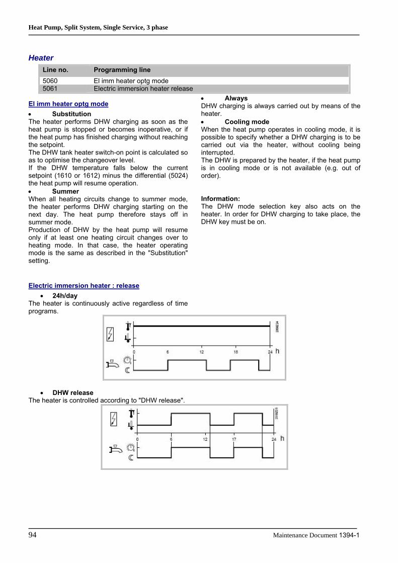
Heat Pump, Split System, Single Service, 3 phase
94 Maintenance Document 1394-1
Heater Line no. Programming line 5060 El imm heater optg mode 5061 Electric immersion heater release
El imm heater optg mode • Substitution The heater performs DHW charging as soon as the heat pump is stopped or becomes inoperative, or if the heat pump has finished charging without reaching the setpoint. The DHW tank heater switch-on point is calculated so as to optimise the changeover level. If the DHW temperature falls below the current setpoint (1610 or 1612) minus the differential (5024) the heat pump will resume operation. • Summer When all heating circuits change to summer mode, the heater performs DHW charging starting on the next day. The heat pump therefore stays off in summer mode. Production of DHW by the heat pump will resume only if at least one heating circuit changes over to heating mode. In that case, the heater operating mode is the same as described in the "Substitution" setting.
• Always DHW charging is always carried out by means of the heater. • Cooling mode When the heat pump operates in cooling mode, it is possible to specify whether a DHW charging is to be carried out via the heater, without cooling being interrupted. The DHW is prepared by the heater, if the heat pump is in cooling mode or is not available (e.g. out of order). Information: The DHW mode selection key also acts on the heater. In order for DHW charging to take place, the DHW key must be on.
Electric immersion heater : release • 24h/day
The heater is continuously active regardless of time programs.
• DHW release The heater is controlled according to "DHW release".

Heat Pump, Split System, Single Service, 3 phase
Maintenance Document 1394-1 95
• Time program 4/DHW Time program 4/DHW of the local controller is taken into account for the heater.
Information: Switch-on will actually be in effect only if the heater is able to operate according to the "heater operating mode" setting.
6.3.10 Configuration Functions When an installation is started up, the hydraulic diagram presetting for that installation must be entered.
Presettings Line no. Programming line 5700 Preselection
Cooling Circuit 1 Line no. Programming line 5711 Cooling circuit 1 (Off / 4-pipe system / 2-pipe system)
Off The cooling circuit is deactivated.
4-pipe system: Not compatible with the Waterstage heat pump. This setting relates to passive cooling.
2-pipe system: Activates the heat pump cooling mode. However, the cooling kit must have been previously connected.
Warning: If the cooling kit has not been connected and the cooling mode is activated the heat pump will behave abnormally and might cause some unwanted discomfort. Information: Switching on the cooling mode causes the menu '"Cooling circuit 1" to appear.
Combi storage tank Line no. Programming line 5870 Combi storage tank
Cont type input EX Line no. Programming line 5987 Cont type input EX4 5989 Cont type input EX5

Heat Pump, Split System, Single Service, 3 phase
96 Maintenance Document 1394-1
Input H2 Function Input H2 is available only on the control extension module. No more than two extension modules can be fitted into an installation. In this case the settings on
contact H2 will be assigned to the module with address 1. Only one function can be assigned to input H2 even if there are two modules.
Line no. Programming line 6046 Function Input H2 6047 Contact type H2 6048 Function value Contact H2
Function Input H2 • Operating mode changes: o Heating circuits The operating mode for the heating circuit(s) is changed via terminal H2 (e.g. telephone contact) to protection mode. o Domestic hot water Domestic hot water charging lock is active only with setting 1 (heating circuits + DHW). All temperature demands from heating circuits and DHW are ignored. Frost protection is active during this time. • Error/alarm message The closing of input H2 causes an internal error message from the controller. • Dewpoint sensor A dewpoint sensor can be connected to input H2 to detect condensation. If it responds, the cooling circuit is immediately switched off. The cooling circuit is reactivated only if the sensor goes off after the adjustable lock time (line 946) has elapsed. • Swimming pool release This function enables the swimming pool to be directly heated with the boiler and pump H2 via an external device (e.g. manual switch).
Direct charging always requires release on input H2. For configuration: set input H2 to "Swimming pool release" and wire the contact. Warning: If there are two extension modules (e.g.: 2nd zone + pool) the second zone module have the address 1 and the pool module must have the address 2 because contact H2 enabling the swimming pool mode must be wired to the address 1.
Contact type H2 • Normally closed The contact is normally closed and must be open to activate the selected H2 function. • Normally open The contact is normally open and must be closed to activate the selected H2 function.
Function value Contact H2 The function value contact H2 is operated only when the parameter 6046 is setting on “release swimming pool”. This function allows to set the temperature of the water which goes on the swimming pool heat exchanger.
Sensor Corrections Line no. Programming line 6100 Readjustm outside sensor
The outdoor temperature measuring value can be corrected within a range of +/- 3 K.

Heat Pump, Split System, Single Service, 3 phase
Maintenance Document 1394-1 97
Installation Frost Protection Line no. Programming line 6120 Frost protection for the plant
According to the outdoor temperature, the heating circuit pump and the condenser pump are switched on although there is no demand for heat
Miscellaneous Line no. Programming line 6205 Reset to default parameters 6220 Software version
Reset to default parameters : All parameters can be reset to factory settings, except when it comes to the following pages: Time and date, User interface and all time programs, as well as the operating hours and the various counters.
Software version: The software version represents the controller software status at the time the unit is being produced. It is printed on the back of the unit. The first two digits represent the software version, and the third is the revision number (e.g. 01.0)
6.3.11 Error Functions When a fault occurs, the symbol appears and it is possible to display an error message in the Info section by pressing the Info key.
The display shows what caused the fault.
Reset (unlock) Heat Pump Line no. Programming line 6711 Reset HP
This line is used to clear the heat pump error messages. The predetermined switch-on delay in case of a failure is therefore ignored, which avoids waiting periods during servicing / troubleshooting.
This option should not be used in normal operating conditions.
Outdoor temperature
Pump Diagram
Continuously ON Set to ON for 10 min, approx. every 6 hours. Continuously off
ON Periodically ON OFF

Heat Pump, Split System, Single Service, 3 phase
98 Maintenance Document 1394-1
Fault Indication Function Line no. Programming line 6740 Flow temp 1 alarm 6741 Flow temp 2 alarm 6745 DHW charging alarm 6746 Flow temp cooling 1 alarm
The difference between the setpoint value and the current temperature value is monitored. Any difference which continues after the set time period has elapsed will trigger an error message.
Fault History Line no. Programming line 6800 to 6818 Time stamp and history of faults 1 -10
The controller saves the last 10 faults which have occurred to a non volatile memory. Any new entry will delete the oldest entry from the memory. A fault code and a time are saved for each fault.
Error Code List Designation of error The error designations in the table below are displayed in plain text on the user interface. Location The sensor or contact associated to the error message. Reset Reset is either automatic or manual, depending on the type of error (see table below with error messages). Manual reset Errors which are displayed in the Info section and accompanied by the "Reset?" question can be manually reset. Press the "OK" key once, "yes" flashes on the display. Press the "OK" key again to confirm the "yes" and the error will be reset. Automatic reset Automatic clearing occurs after a previously set time (OEM setting) has elapsed. After this timeout (6 hours by default) has elapsed, the controller will attempt to reset the error. If "Number" appears in the table, it is possible to define how many times the fault can be reset before the heat pump is declared out of order.
Heat pump operation Shows whether or not the heat pump can continue to operate when the error occurs. Yes The heat pump continues to operate despite the error message. No The error interrupts operation of the heat pump. No with glycol water This error stops glycol water heat pumps, but does not prevent operation of water or air heat pumps. No with water This error stops water heat pumps, but does not prevent operation of glycol water heat pumps No with air This error stops air heat pumps, but does not prevent operation of water heat pumps or glycol water heat pumps. Per diagram The heat pump will be stopped according to the current installation diagram. Alarm messages Errors are ranked by priority. From priority 5 onward (i.e. priority levels 5 - 9) the alarm messages used in remote control (OCI) are sent. In addition, the alarm relay is switched on.

Heat Pump, Split System, Single Service, 3 phase
Maintenance Document 1394-1 99
Table of error messages which can be displayed: Reset No. Designation of error Location Manual Automatic HP oper. Priority
0: No fault 10: Outdoor sensor B9 No No Yes 6 30: Flow sensor 1 B1 No No Yes 6 31: Cooling flow sensor 1 B16 No No Yes 6 32: Flow sensor 2 B12 No No Yes 6 33: Heat pump flow temp sensor error B21 No No Yes 6
44: Heat pump return temp sensor error B71 No No per diagram 6
50: DHW temp sensor 1 B3 No No Yes 6 60: Room sensor 1 No No Yes 6 65: Room sensor 2 No No Yes 6 76: Special sensor 1 BX No No Yes 3 83: BSB wire short-circuit No No Yes 8 84: BSB, address collision No No Yes 3 85: Radio communication error No No Yes 8 98: Extension module 1 No No Yes 8 99: Extension module 2 No No Yes 8 100: 2 master clocks on bus No No Yes 3 102: Clock without running supply No No Yes 3
105: Maintenance message No No Yes 5 121: HC1 flow temp too low No No Yes 6 122: HC2 flow temp too low No No Yes 6 126: DHW charge monitoring No No Yes 6 127: Anti-legionella temperature No No Yes 6 134: Heat pump alarm summary E20 Yes Number * No 9 138: No heat pump control sensor No Yes No 1
146: Sensor / control device configuration No No Yes 3
171: Alarm contact 1 activated No No Yes 6 172: Alarm contact 2 activated H2 No No Yes 6 176: Hydraulic pressure 2 too high H2 No No Yes 6
177: Hydraulic pressure 2 too low H2 No No No 6
178: HC1 safety thermostat No No Yes 3 179: HC2 safety thermostat No No Yes 3 201: Frost alarm B21/71 Yes No No 9 243: Swimming pool sensor B13 No No Yes 6 325: BX/ext unit: same sensors No No Yes 3 327: Ext modules: same functions No No Yes 3
329: Ext modules/mixing grp: same functions No No Yes 3
330: BX1 no function No No Yes 3 331: BX2 no function No No Yes 3 332: BX3 no function No No Yes 3 333: BX4 no function No No Yes 3 334: BX5 no function No No Yes 3 335: BX21 no function No No Yes 3 336: BX22 no function No No Yes 3 357: cooling circuit flow temp not reached No No Yes 6
359: no cooling valve Y21 No No Yes 3

Heat Pump, Split System, Single Service, 3 phase
100 Maintenance Document 1394-1
Reset 360: no process reversing valve Y22 No No Yes 3
364: Heat pump cooling system error No No Yes 3
369: External fault No 370: Outdoor unit fault No
Number* If such statuses or events occur for the first time, they will not directly generate a fault message, but only a status message.
Only if the anomaly occurs repeatedly over a predefined time period and at a given frequency (number) will an error message be generated.

Heat Pump, Split System, Single Service, 3 phase
Maintenance Document 1394-1 101
6.3.12 Maintenance / Special Operating Mode Functions
Maintenance Maintenance functions can be used as a preventive step for periodically monitoring the installation. All maintenance functions can be individually activated / deactivated.
The controller automatically generates maintenance messages if the settings defined are either exceeded or fail to be reached.
Line no. Programming line 7070 HP interval 7071 HP time since maint 7072 Max starts compr1/hrs run 7073 Cur starts compr1/hrs run 7076 Diff condens max/week 7077 Cur diff condens max/week 7078 Diff condens min/week 7079 Cur diff condens min/week 7090 DHW storage tank interval 7091 DHW stor tank since maint
HP interval : Defines the maintenance frequency (in months) for the heat pump.
HP time since maint : Displays the time (months) elapsed since the last maintenance. If the value exceeds the "heat pump interval" setting (Line 7070), the symbol will be displayed and a maintenance message will appear in the Info section: 17: Heat pump maintenance Interval (Priority 6)
This setting can be reset with the associated rights of access.
Max starts compr1/hrs run : Defines the maximum number of compressor 1 startups per hour of operation.
Cur starts compr1/hrs run : The average number of compressor startups per hour of operation, obtained over a period of 6 weeks. If the value exceeds the "Comp1 max startups/hr op" adjusted setting, the symbol will be displayed and a maintenance message will appear in the Info section: 8: Too many compressor 1 startups (Priority 9) This setting can be reset with the associated rights of access.
Diff condens max/week : This setting indicates how many times over 7 days the maximum temperature difference on the condenser can be exceeded.
Cur diff condens max/week: Number of times the maximum temperature difference on the condenser has been exceeded during a 7-day period. If the value exceeds the setting "Max cond diff/week" (line 7076), the symbol will be displayed and a maintenance message will appear in the Info section: 13: Max cond diff (Priority 3) This setting can be reset with the associated rights of access.
Diff condens min/week : Indicates how many times over 7 days the minimum temperature difference on the condenser may fail to be reached.
Cur diff condens min/week (7079): The number of times the minimum temperature difference on the condenser has not been reached over a 7 period. If the value is higher than the setting "Min cond diff/wk" the symbol will be displayed and a maintenance message will appear in the Info section: 14: Min cond diff (Priority 3) This setting can be reset with the associated rights of access.
DHW storage tank interval (7090): Adjustment of the maintenance frequency (in months) of the DHW tank.
Heat Pump, Split System, Single Service, 3 phase
102 Maintenance Document 1394-1
DHW stor tank since maint (7091): The time elapsed (in months) since the last maintenance. If the value is greater than the setting "DHW tank interval" (Line 7090), this symbol will be displayed and a maintenance message will appear in the Info section: 11: TWW DHW tank period (Priority 6)
Emergency mode If the heat pump is not operating properly, a emergency service can be maintained. The emergency mode enables the installation to be run
with the available heaters (flow, storage tank, DHW tank). In this case the compressor will remain off.
Line no. Programming line 7141 Emergency operation 7142 Emergency operation function type
Emergency operation (7141): Emergency operation can be activated and deactivated manually. • Off: Emergency operation is deactivated. • On: Emergency operation is activated.
Emergency operation function type (7142): • Manual: Emergency operation can be activated/deactivated only through the Emergency operation setting on line 7141. • Automatic: As soon as a fault occurs on the heat pump, emergency operation is automatically switched on. It stops when the fault is removed and, if necessary, cleared (reset). Emergency mode may however be activated / deactivated manually via the "Emergency operation" setting on line 7141.
Simulation Line no. Programming line 7150 Simulation outside temp
Simulation outside temp (7150): To make the starting-up and troubleshooting processes easier, it is possible to simulate an outdoor temperature in the range of -50...+50°C. During simulation, the current, composite and attenuated outdoor temperatures are ignored and substituted with the adjusted simulation temperature.
Computation of the three outdoor temperatures based on the actual outdoor temperature continues to be performed during the simulation, and these temperatures are available again when the simulation is over. This function can be deactivated by selecting -.- on this line or automatically, after a 5 hour waiting period.
Person in charge Line no. Programming line 7181, 7183 Telephone number of person in charge
These lines are used to specify the telephone numbers associated with the corresponding alarms.

Heat Pump, Split System, Single Service, 3 phase
Maintenance Document 1394-1 103
6.3.13 Input / Output Testing Functions Input/output testing is used to ensure that the connected components are in working order.
Relay Output Testing Selection of a setting from relay testing closes the corresponding relay and therefore switches on the connected component. This makes it possible to
check that the relays are in working order and that the wiring has been performed correctly.
Line no. Programming line 7700 Relay test
(No test / All OFF / Relay output QX23 Module 1 / Relay output QX21 module 1 / Relay output QX22 module 1 / Relay output QX1 / Relay output QX2 / Relay output QX3 / Relay output QX4 / Relay output QX5 / Relay output QX6 / Relay output QX23 Module 2 / Relay output QX21 Module 2 / Relay output QX22 Module 2 / Relay output QX7)
Warning: During testing of an output, the heat pump is stopped, all outputs are "off" and only the controlled output is on.
Analog Input/Output Testing Line no. Programming line 7710 Output test UX 7711 Voltage signal UX 7720 Digital output test 7721 Digital output DO1 7722 Digital output DO2
Output test UX Enables testing the outdoor unit control.
Voltage signal UX Displays the voltage value at the UX output.
Digital output test Enables testing outputs DO1 and DO2
Digital output DOx Shows the output status.
Sensor Input Testing Line no. Programming line 7730 Outside temp B9 7820 Sensor temp BX1 7823 Sensor temp BX4 7824 Sensor temp BX5 7830 Sensor temp BX21 module 1 7831 Sensor temp BX22 module 1 7832 Sensor temp BX21 module 2 7833 Sensor temp BX22 module 2
Displays the temperature of each sensor.
H1, H2, H3 Input Testing Line no. Programming line 7841 Contact state H1 7846 Contact state H2 7855 Contact state H3
Displays the momentary status of contact Hx.
Heat Pump, Split System, Single Service, 3 phase
104 Maintenance Document 1394-1
Input Testing Line no. Programming line 7914 Input EX4 7915 Input EX5 7916 Input EX6
If a test setting is selected, the associated input is displayed and can thus be checked. The "0 V" display means that there is no voltage and that the respective input is currently inactive. The
"230 V" display indicates that a 230 V voltage is present on the associated input and therefore, that the input is active.
6.3.14 Status Functions The current operating status of the installation can be viewed by means of status displays.
Messages Line no. Programming line 8000 State heating circuit 1 8001 State heating circuit 2 8003 State DHW 8004 State cooling circuit 1 8006 State heat pump 8011 State swimming pool 8022 State supplementary source

Heat Pump, Split System, Single Service, 3 phase
Maintenance Document 1394-1 105
State heating circuit
End user (Info level) Startup, heating engineer Thermostat response Thermostat response Manual action active Manual action active Controlled drying active Controlled drying active Heating mode restriction Overeating protection active
Restriction, Boiler protection Restriction, DHW priority Restriction, storage tank
Forced draft Forced draft, storage tank Forced draft, DHW Forced draft generator Forced draft Switch-off delay active
Comfort heating mode Optimis. at switch-on + accelerated heating Optimisation at switch-on Accelerated heating Comfort heating mode
Reduced heating mode Optimisation at switch-off Reduced heating mode
Frost protection active Room frost protection Flow frost protection active Install. frost protection active
Summer mode Summer mode Off Eco day active
Reduced decrease Frost protection decrease Room temperature limitation Off

Heat Pump, Split System, Single Service, 3 phase
106 Maintenance Document 1394-1
State DHW (8003):
End user (Info level) Startup, heating engineer Thermostat response Thermostat response Manual action active Manual action active Draw-off mode Draw-off mode Adiabatic cooling active Adiabatic cooling by collector
adiabatic cooling via gen/HC Charging lock active Discharge protection active
Charging duration limit. active Charging locked
Forced charging active Forcing, DHW tank max temp Forcing, max charging temp Forcing, anti-legion. setpoint Forcing, comfort setpoint
Charging by heater Charging by heater, anti-legion. setpoint Charging by heater, Comfort setpoint Charging by heater, Reduced setpoint Charging by heater, frost protection setpoint Heater released
Accelerated charging active Flow active Anti-legion. accelerated charging
Charging active Charging, anti-legion. setpoint Charging, Comfort setpoint Charging, Reduced setpoint
Frost protection active Frost protection active Switch-off delay active Switch-off delay active Charging on standby Charging on standby Charged Charged, max tank temp
Charged, max charging temp Charged, anti-legionella temp Charged, comfort temp Charged, reduced temp
Off Off Ready Ready

Heat Pump, Split System, Single Service, 3 phase
Maintenance Document 1394-1 107
State cooling circuit (8004):
End user (Info level) Startup, heating engineer Dewpoint sensor activated Dewpoint sensor activated Manual action active Manual action active Fault Fault Frost protection active Flow frost protection active Cooling mode locked Locked, heating mode
Lock time after heating Locked, generator Locked, storage tank
Cooling mode restricted Flow temp setpoint increase by hygrostat Dewpoint flow min limit Outdoor temp flow min limit
Comfort cooling mode Comfort cooling mode Switch-off delay active
Cooling protection mode Cooling protection mode Frost protection active Frost protection active OT cooling limit activated OT cooling limit activated Off Off
Room temperature limitation Flow limit reached
Cooling mode off Cooling mode off

Heat Pump, Split System, Single Service, 3 phase
108 Maintenance Document 1394-1
State heat pump (8006):
End user (Info level) Startup, heating engineer Emergency mode Emergency mode Fault Fault Locked Locked, outdoor temperature
Locked, external Locked, economy mode
Lim. time active Consumer flow rate controller Min outdoor temp use limit Max outdoor temp use limit Max switchoff temp lim Max OT limit cooling Min switchoff temp limit Comp min switchoff time active Excess heat compensation
Frost protection active Heat pump frost protection Defrosting activated Defrosting activated Cooling mode active Comp min ON time active
Comp 1 ON
Heating Comp min ON time active Heat deficiency compensation Max cond diff limit Min cond diff limit Comp.1 and heater ON Comp 1 ON Heater ON
Frost protection active Install. frost protection active Off Flow active
Switch-off delay active No demand
State swimming pool (8011):
End user (Info level) Startup, heating engineer Manual action active Manual action active Fault Fault Heating mode restriction Heating mode restriction Forced draft Forced draft Heating Generator heating mode Heated, max pool temp Heated
Heated, max pool temp Heated, generator setpoint
Heating off Solar heating mode OFF Generator heating mode OFF
Cooling Cooling

Heat Pump, Split System, Single Service, 3 phase
Maintenance Document 1394-1 109
State supplementary source (8022):
End user (Info level) Startup, heating engineer Locked Locked, solid fuel boiler
Locked, outside temperature Locked, economy mode
In operation for HC, DHW In operation for HC, DHW Released for HC, DHW Released for HC, DHW In operation for DHW In operation for DHW Released for DHW Released for DHW In operation for heating circuit In operation for heating circuit In operation for HC, DHW In operation for HC, DHW Released for HC, DHW Released for HC, DHW In operation for DHW In operation for DHW Released for DHW Released for DHW In operation for heating circuit In operation for heating circuit Released for HC Released for HC Overrun active Overrun active Off. Off.
History: Line no. Programming line 8050 – 8068 Timestamping and history status coding of faults 1 - 10
The last 10 status messages are saved and displayed with the associated codes. The most recent message is saved to History 1, the oldest to History 10.
Information: Status displays for the end user can be viewed directly in the Info section on the room unit.
6.3.15 Generator Diagnosis Functions Various setpoints and actual values, relay switch status data can be displayed for purposes of diagnosis.
Heat Pump: Line no. Programming line 8402 El imm heater 1 flow 8403 El imm heater 2 flow 8406 Condenser pump
These command lines are used to check the operating mode of the components controlled by the heat pump relays. The display "0" means that the associated components are currently disconnected. The display "1" means that the associated components are currently switched on.
Information This information applies to relays defined as normally open contacts. For normally closed contacts, the action is reversed.

Heat Pump, Split System, Single Service, 3 phase
110 Maintenance Document 1394-1
Setpoints and Measured Values Line no. Programming line 8410 Return temp HP 8412 Flow temp HP 8413 Compressor modulation 8425 Temp diff condenser
These lines allow the various setpoints and measured values for the heat pump to be viewed.
Hour / Startup Counter Line no. Programming line 8454 Locking time HP 8455 Counter number of locks HP 8456 Hours run el flow 8457 Start counter el flow
Locking time HP Displays the cumulative locking time since start-up by the electrical services (via E6).
Heat pump lock counter Displays the cumulative locks since start-up by the electrical services (via E6).
Hours run el flow, Start counter el flow These lines are used to view the hours of operation and the number of startups of electric heater.
6.3.16 Consumer Diagnosis Functions Various setpoints and actual values, relay switch status and timing status data can be displayed for purposes of diagnosis.
Outdoor Temperatures Line no. Programming line 8700 Outside temperature 8701 Outside temp min 8702 Outside temp max 8703 Outside temp attenuated 8704 Outside temperature composite
The current, minimum, maximum, attenuated and composite outdoor temperatures are displayed.
Heating Circuits Line no. Programming line 8730 and 8760 heating circuit pump 8731 and 8761 Heating circ mix valve open 8732 and 8762 Heat circ mix valve close 8740 and 8770 Room temp 8743 and 8773 Flow temp
The display "Off" means that the associated components are currently disconnected. The display "On" means that the associated components are currently switched on.

Heat Pump, Split System, Single Service, 3 phase
Maintenance Document 1394-1 111
Cooling Circuit Line no. Programming line 8756 Flow temperature cooling 1
The actual values of the cooling mode are displayed. The cooling mode room setpoint is displayed on
programming line 8741.
Domestic Hot Water Line no. Programming line 8820 DHW pump 8821 Electric immersion heater DHW 8830 DHW temp 1 8840 Hours run DHW pump 8841 Start counter DHW pump 8842 Hours run el DHW 8843 Start counter el DHW
The measured values, the DHW circulation pump and charging temperature, operating hour and startup
counters are displayed, as well as temperatures of the primary controllers and DHW heater.
Swimming Pool Line no. Programming line 8900 Swimming pool temp
The current temperature of the swimming pool is displayed.
Line Line no. Programming line 8950 Common flow temp
Multifunction Relay Status Line no. Programming line 9031 Relay output QX1 9032 Relay output QX2 9033 Relay output QX3 9034 Relay output QX4 9035 Relay output QX5 9036 Relay output QX6 9037 Relay output QX7
The switching status of multifunction relays 1 - 6 can be viewed individually on these lines. The display "Off" means that the components assigned to this
output are currently disconnected. The display "On" means that the associated components are currently switched on.
Heat Pump, Split System, Single Service, 3 phase
112 Maintenance Document 1394-1
Status of Relays for Extension Modules 1 and 2 Line no. Programming line 9050 Relay output QX21 module 1 9051 Relay output QX22 module 1 9052 Relay output QX23 module 1 9053 Relay output QX21 module 2 9054 Relay output QX22 module 2 9055 Relay output QX23 module 2
The switching status of the relays connected to extension modules 1 and 2 can be viewed on these programming lines.
The display "Off" means that the components assigned to this output are currently disconnected. The display "On" means that the associated components are currently switched on.

Heat Pump, Split System, Single Service, 3 phase
Maintenance Document 1394-1 113
7 Annual Maintenance Services
7.1 Hydraulic Circuit • clean filter (if any) • inspect heating system (system pressure,
purging, leak test) • inspect expansion vessel (preload with nitrogen
at 1 bar) • fix any leaks
7.2 Outdoor unit • clean heat exchanger • clean refrigeration and ventilation compartment • check for correct condensation drain • conduct refrigeration circuit leak test (required if
charged > 2 kg)
7.3 Electrical • Inspect connections and tighten where
appropriate • Check condition of wires and boards
7.4 Operating checks • conduct refrigeration readings at temperatures • in case of malfunction, install pressure gauges
for refrigeration diagnosis • check voltage, current and control

Heat Pump, Split System, Single Service, 3 phase
114 Maintenance Document 1394-1
8 Connection Diagrams
8.1 Connection Diagram of Hydraulic Unit

Heat Pump, Split System, Single Service, 3 phase
Maintenance Document 1394-1 115
8.2 Connection Diagram of Outdoor Unit
Heat exchanger MID

Heat Pump, Split System, Single Service, 3 phase
116 Maintenance Document 1394-1
9 Disassembly Process of Outdoor Unit
> Warning ! < Before servicing the unit, turn the power supply switch OFF, then, do not touch electric parts for
10 minutes due to the risk of electric shock.
9.1 Appearance
9.2 Service panel removal
9.3 Insulation sheet removal

Heat Pump, Split System, Single Service, 3 phase
Maintenance Document 1394-1 117
9.4 Main PCB removal
9.5 INVERTER, PFC, FILTER, and CAPACITOR PCB removal

Heat Pump, Split System, Single Service, 3 phase
118 Maintenance Document 1394-1
9.5.1 INVERTER PCB removal
9.5.2 PFC PCB removal
9.5.3 FILTER PCB removal

Heat Pump, Split System, Single Service, 3 phase
Maintenance Document 1394-1 119
9.5.4 CAPACITOR PCB removal

Heat Pump, Split System, Single Service, 3 phase
120 Maintenance Document 1394-1
9.6 FAN MOTOR removal
9.7 TOP PANEL removal
9.8 PIPE COVER FRONT removal

Heat Pump, Split System, Single Service, 3 phase
Maintenance Document 1394-1 121
9.9 RIGHT PANEL removal
9.10 REACTOR removal
9.11 THERMISTOR removal
9.11.1 HEAT EXCHANGER (OUT) THERMISTOR
9.11.2 EXPANSION VALVE THERMISTOR

Heat Pump, Split System, Single Service, 3 phase
122 Maintenance Document 1394-1
9.12 SOLENOID COIL removal
9.12.1 4WAY VALVE
9.12.2 INJECTION
9.13 EEV COIL removal
9.13.1 MAIN
9.13.2 INJECTION
9.14 PRESSURE SENSOR removal
> Warning ! < Wear gloves to prevent the frostbite, because a small amount of refrigerant leaks during work.

Heat Pump, Split System, Single Service, 3 phase
Maintenance Document 1394-1 123
9.15 COMPRESSOR removal Precautions for exchange of compressor. Do not allow moisture or debris to get inside refrigerant pipes during work. Procedure for compressor removal. 1 Turn off the power 2 Remove the service panel 3 Fully close the 3Way valve (gas) and 3Way valve (liquid) 4 Collect the refrigerant from the 3Way valve. Start the following work after completely collecting the refrigerant. Do not reuse the refrigerant that has been collected.

Heat Pump, Split System, Single Service, 3 phase
124 Maintenance Document 1394-1
Procedure for compressor installation Reverse procedure to removing the compressor. Precautions for installation of compressor. 1 When brazing, do not apply the flame on the terminal.
2 When brazing, be sure to replace the air in the pipe with nitrogen gas to prevent forming oxidization scale.
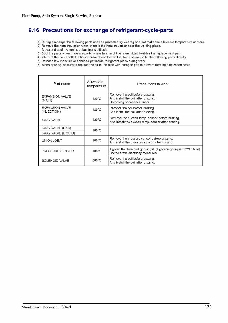
Heat Pump, Split System, Single Service, 3 phase
Maintenance Document 1394-1 125
9.16 Precautions for exchange of refrigerant-cycle-parts
Heat Pump, Split System, Single Service, 3 phase
126 tnemucoD ecnanetniaM 1394-1
10 Spare Parts
The data is being prepared.
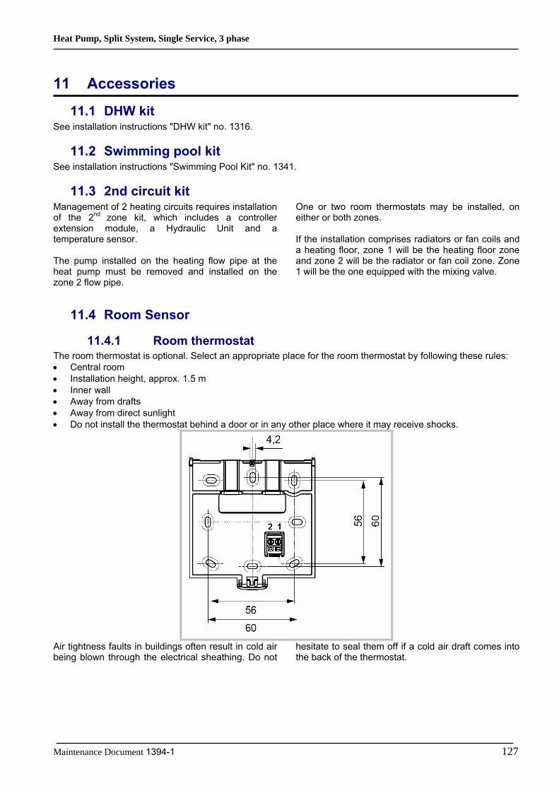
Heat Pump, Split System, Single Service, 3 phase
Maintenance Document 1394-1 127
11 Accessories
11.1 DHW kit See installation instructions "DHW kit" no. 1316.
11.2 Swimming pool kit See installation instructions "Swimming Pool Kit" no. 1341.
11.3 2nd circuit kit Management of 2 heating circuits requires installation of the 2nd zone kit, which includes a controller extension module, a Hydraulic Unit and a temperature sensor. The pump installed on the heating flow pipe at the heat pump must be removed and installed on the zone 2 flow pipe.
One or two room thermostats may be installed, on either or both zones. If the installation comprises radiators or fan coils and a heating floor, zone 1 will be the heating floor zone and zone 2 will be the radiator or fan coil zone. Zone 1 will be the one equipped with the mixing valve.
11.4 Room Sensor
11.4.1 Room thermostat The room thermostat is optional. Select an appropriate place for the room thermostat by following these rules: • Central room • Installation height, approx. 1.5 m • Inner wall • Away from drafts • Away from direct sunlight • Do not install the thermostat behind a door or in any other place where it may receive shocks.
Air tightness faults in buildings often result in cold air being blown through the electrical sheathing. Do not
hesitate to seal them off if a cold air draft comes into the back of the thermostat.

Heat Pump, Split System, Single Service, 3 phase
128 Maintenance Document 1394-1
2284
Z33a
2284
Z34a
2284
Z35a
Connection: The room thermostat must be connected to one of the terminals b (CL+, CL-) of the heat pump controller board. To do this, you can use a 0.5mm² cable of the two-pair telephone cable type.
If the cable is shielded, the shielding can be connected to the controller CL- terminal. It may under no circumstances be connected on both sides, i.e. controller side and room unit side.
If the installation is equipped with 2 room thermostats, the second thermostat must be connected to the second terminal block b. Configuration: Gain access to the settings by continuously pressing the "Heating mode" key fs = 1 (factory setting) The room unit is addressed as ZONE 1 fs = 2 The room unit is addressed as ZONE 2 fs = 3 The room unit is addressed as ZONE 3 (factory setting) P1 = 1 (factory setting) Automatic save: Correction of the setpoint using the knob is accepted without special confirmation (timeout) or by pressing the operating mode key. P1 = 2 Confirm save Correction of the setpoint with the knob is accepted only after pressing the operating mode key.
1 CL+ 2 CL- 1
34
56 2
2284
Z40
User interface

Heat Pump, Split System, Single Service, 3 phase
Maintenance Document 1394-1 129
11.4.2 Remote control The remote control includes the functions of the room unit together with those of the user interface mounted in series on the Hydraulic Unit. It can be used, therefore, not only to measure the room temperature, but also to view the operating
status of the heat pump, to enter the pump settings appropriate to the house and to the application's hydraulic circuit.
Installation
Select heating mode
Select DHW mode
Exit setting
Confirm setting
Adjust Comfort temp setpoint Navigation and settings.
Occupancy key
Display information

Heat Pump, Split System, Single Service, 3 phase
130 Maintenance Document 1394-1
Connections The room central unit must be connected to terminal b (CL+, CL-, G+) of the heat pump controller board. To do this, you can use a 0.5mm² cable of the two-pair telephone cable type.
If the cable is shielded, the shielding can be connected to the controller CL- terminal. It may under no circumstances be connected on both sides, i.e. controller side and room unit side.
Terminal T75 Control terminal Function 1 CL+ BSB data 2 CL- BSB ground 3 G+ Power supply 12
11.5 Boiler connection kit An oil or gas boiler may be connected to the heat pump. Such a connection requires the purchase of the backup kit module, which includes a 3-way selection valve designed to isolate the boiler, and a pressure breaker. When a boiler is connected to the heat pump, the electric auxiliaries installed in the heat pump must not
be connected, as it is the boiler which provides additional heating on the coldest days. The boiler is controlled by the heat pump. If the boiler has its own control system, you must disconnect or disable the system by assigning it the highest setpoint.
11.6 Cooling kit See installation instructions "cooling kit" no. 1357.
11.7 High flow rate circulation pump kit See installation instructions "High flow rate circulation pump kit" no. 1360.
11.8 Heat exchanger for swimming pool See installation instructions "Heat exchanger for swimming pool" no. 1345.
11.9 DHW tank See installation instructions "DHW tank".
11.10 Balancing vessel See installation instructions "Balancing vessel".
11.11 External connect kit See installation instructions "External connect kit".

Heat Pump, Split System, Single Service, 3 phase
Maintenance Document 1394-1 131
12 Related Documents
12.1 Quick-Start Procedure Before switching on the Hydraulic Unit:
1. Check the electric wiring 2. Check the refrigeration circuit and make sure the gas supply has been performed 3. Check the hydraulic circuit, with 1-2 bar pressure, check that the heat pump is purged, as well as the
rest of the installation. 4. Check the DIP SW on the interface PCB. (All switches must be set OFF).
1. Set the front interface On 2. Configure the hydraulic circuit (setting 5700): Presettings:
1. Waterstage 1 heating circuit (by default) 2. Waterstage 1 heating circuit and DHW tank. 3. Waterstage 2 heating circuits. 4. Waterstage 2 heating circuits and DHW tank. 5. Waterstage boiler backup and 1 heating circuit. 6. Waterstage boiler backup and 2 heating circuits. 7. Waterstage boiler backup, 1 heating circuit and DHW tank. 8. Waterstage boiler backup, 2 heating circuits and DHW tank.
3. Time, Date and time programs for HC1, HC2, DHW if other than default values (settings 500 – 576) 4. Adjust the heating curve slope (720; 1020) and displacement (721; 1021)
The heat pump is ready for operation! You can also:
1. Adjust HC setpoints if other than default values (710 – 714; 1010-1014) 2. Adjust DHW setpoints (1610-1612) if other than default values 3. Start a legionella cycle (1640-1647) 4. Perform floor drying (850-857)

Heat Pump, Split System, Single Service, 3 phase
132 Maintenance Document 1394-1
12.2 Startup Checklist Date: .................................................... Installation identification: ................................................................
.............................................................................................................. After Sales Service identification: ...............................................................
Installer identification: ...................................................................... ..............................................................................................................
Unit reference number: ...................... Serial number: ............................................................................... BEFORE STARTING UP Sight Checks Outdoor unit: (See "Outdoor unit Installation" section of "Installation" instructions) OK NON COMPLIANT location and fittings, condensate evacuation compliance with distances from obstacles Hydraulic Checks Hydraulic unit: (See "Hydraulic Connections" section of "Installation" instructions) OK NON COMPLIANT VALUE connection of pipes, valves and pumps (1 or 2 circuits, DHW) installation water volume (expansion vessel of adequate capacity?) No leaks Main system pressure and degassing (0.3b > Exp vessel pre-loading) Refrigeration Connections and Checks (See “ Refrigeration Connections and Gas Supply" section of "Installation" instructions ) OK NON COMPLIANT Connections between units (pipe length, flared joints, etc.) Installation of HP, LP pressure switches on liquid line (small pipe) Pumpdown required Nitrogen leak test (~ 25 bar) Refrigerant filling of Hydraulic Unit and pipes opening of refrigeration valves to Outdoor Unit Electrical Checks Outdoor unit: See "Electrical Connections" section of "Installation" instructions) OK NON COMPLIANT VALUE 400v main power supply Protection by rated circuit breaker Cable cross-section Connection to earth Hydraulic unit: (See "Hydraulic unit Electrical Connections" section of "Installation" instructions) OK NON COMPLIANT Connection with OU (3 + Earth) Connection of Sensors (positioning and connections) Connection of 3-way valve and pumps. Power supply and protection of electric auxiliary
OBSERVATIONS
_________________________________________________________________________________________ _________________________________________________________________________________________ _________________________________________________________________________________________
ALL PERSONS PRESENT AT STARTUP MUST SIGN USER
INSTALLER VENDOR AFTER SALES

Heat Pump, Split System, Single Service, 3 phase
Maintenance Document 1394-1 133
STARTING UP Switching On (See "Starting up" section of "Installation" instructions) OK NON COMPLIANT Switching on Initialisation for a few seconds Operation of the pumps Outdoor unit starts after 3mins Checks on Outdoor Unit OK NON COMPLIANT VALUE Operation of fan(s), compressor Current measurement After a few minutes, measurement of air temp delta Check condensation and evaporation pressure/temperature Checks on Hydraulic Unit OK NON COMPLIANT VALUE after 15 minutes of operation primary water temp delta DHW priority (switching of selection valve) operation of heating, mixing valve, boiler backup, etc. Control settings Room Control (See "Room Sensor Configuration" section of "Installation" instructions) OK NON COMPLIANT Settings, manipulations, checks Setpoint display Explanations on use
OBSERVATIONS ___________________________________________________________________________________________________________________________________________________________________________________________________________________________________________________________________________________________________________________________________________________________________________________________________________________________________________________________________________________________________________________________________________________________________________________________________________________________________________________________________________________________________________________________________________________________________________________________________________________________________________________________________________________________________________________________________________________________________________________________________________________ _________________________________________________________________________________________ _________________________________________________________________________________________
ALL PERSONS PRESENT AT STARTUP MUST SIGN USER
INSTALLER VENDOR AFTER SALES

Heat Pump, Split System, Single Service, 3 phase
134 Maintenance Document 1394-1
12.3 Settings Sheet Setting Description set to Menus Setting Description set to Menus
Preliminary settings Boiler backup 20 language Op. section 3700 Release below out. temp Suppl. source. 1 hour / minutes time and date 3705 Overrun time Suppl. source. 2 day / month time and date Miscellaneous 3 year time and date 6046 Function Input H2 9 configuration
5700 Preselection configuration 6100 Readjustm outside sensor configuration 6120 Frost protect. for the plant configuration Heating circuit No. 1
if 2 circuits =less warmer one (e.g. floor) 6205 Reset to default param. configuration 710 Comfort heating setpoint Heat. circuit 1 6220 software version configuration 712 Reduced setpoint Heat. circuit 1 6711 Reset HP errors 720 Heating curve slope Heat. circuit 1 7070 to 7183 maintenance Serv / special op. 750 Room influence Heat. circuit 1 7700 to 7916 input/output testing I/O test
790 / 791 Opt start/stop control max Heat. circuit 1 8402 to 8457 generator diagnosis Diagn. heat source834 Acutuator running time Heat. circuit 1 8700 to 9055 consumer diagnosis Diagn.consumers
850 / 851 Floor curing Heat. circuit 1 Cooling 501 to 516 time programs HC1 time pgm 5711 Cooling circuit 1 2 pipes configuration 642 to 648 holiday programs Hol. HC1 901 to 969 cooling settings cooling circuit 1
Heating circuit no. 2 (with 2nd circuit option) = warmer one (e.g. radiators)
Faults If a fault occurs, press "Info" key
1010 Comfort heating setpoint Heat. circuit 2 No. 10 outdoor sensor 1012 Reduced setpoint Heat. circuit 2 No. 33 flow temp sensor 1020 Heating curve slope Heat. circuit 2 No. 44 return temp sensor 1050 Room influence Heat. circuit 2 No. 50 DHW temp sensor
1090 / 1091 Opt start/stop control max Heat. circuit 2 No. 60 room sensor 1 1134 Acutuator running time Heat. circuit 2 No. 65 room sensor 2
1150 / 1151 Floor curing Heat. circuit 2 No. 105 maintenance message 521 to 536 time programs HC2 time pgm No. 121 HC1 flow T not reached 652 to 658 holiday programs Hol. HC2 No. 122 HC2 flow T not reached
Domestic Hot Water (if DHW kit) No. 127 Leg. prot. T not reached 1610 Nominal setpoint DHW No. 369 external fault (EX6) 1612 Reduced setpoint DHW No. 370 Outdoor unit connect error 1620 Release DHW 6740 to 6746 alarm timeout errors
1640 to 1647 Legionella cycle DHW 6800 to 6818 last 10 alarms history errors 1660 Circulation pump release DHW 6711 reset HP errors 5020 Flow setpoint boost DHW stor. tank Heat Pump 5024 Switching differential DHW stor. tank 2844 Switch-off temp max Heat pump 5030 Charging time limitation DHW stor. tank 2884 Release el flowat OT heat pump
5060 El imm heater optg mode fill DHW stor. tank 2920 In case of peak day clearing signal lock (EX4) heat pump
5061 Elec imm. heater:release DHW stor. tank Swimming Pool (with"sw pool" kit option) 5870 Combi storage tank configuration 2056 Setpoint source heating sw pool
561 to 576 time programs prog.4 DHW
Outdoor Unit Faults
Refer to "installation" instructions

Heat Pump, Split System, Single Service, 3 phase
Maintenance Document 1394-1 135
12.4 Startup Data Sheet Site: Installer:
Serial no.: Serial no.: Outdoor unit Model:
Hydraulic Unit Model:
Refrigerant type: Refrigerant charge: kg
Checks Operating voltage and current on Outdoor Unit Compliance with positioning distances L1/N, L2/N, L3/N : V
Condensate evacuation correct L1/E, L2/E, L3/E : V
Electric connections/connections tightness N/E: V
No GAS leaks (Unit ID No.: ______) Icomp: A
Installation of refrigeration connection correct (length: m) Reading in HEATING operating mode
Compressor discharge temperature: ______°C Liquid line temp °C
Condensation temp HP = ______bars °C Sub-Cooling =______°C
Tank water output temp °C T condensation = ______°C
Tank water input temp °C T secondary = ______°C
Evaporation temp LP = ______ bars °C
Suction temp °C Overheating =______°C
Heat exchanger air input temp °C T Evaporation = ______°C
Heat exchanger air output temp °C T Heat exchanger = ______°C Hydraulic system on Hydraulic Unit:
Low temp heating floor Pump brand: ___________ Type:__________
LT Radiators
Secondary system:
Fan coils Pump brand: ___________ Type:__________
Domestic hot water: tank type =_______
Pump brand: ___________ Type:__________
Estimated water volume of secondary system: ______ L Options & Accessories:
Power supply for connected electric auxiliary
Operation in cooling mode possible Room thermostat C 55
Location of room sensor correct
Remote control C75
Cooling kit Boiler kit: _____________
DHW kit
2-zone kit
Details:
Control Settings: Configuration type:
Essential settings:
Observations
Startup Date Name and signature of person in attendance Name and signature of Technician

Heat Pump, Split System, Single Service, 3 phase
136 Maintenance Document 1394-1
Fujitsu General (Euro) GmbH Werftstrasse 20
40549 Düsseldorf - Germany