Embed Size (px)
Citation preview

Waters e2795 Separations Module
Operator’s Guide
Revision B
Copyright © Waters Corporation 2008−2010All rights reserved

Copyright notice
© 2008−2010 WATERS CORPORATION. PRINTED IN THE UNITED STATES OF AMERICA AND IN IRELAND. ALL RIGHTS RESERVED. THIS DOCUMENT OR PARTS THEREOF MAY NOT BE REPRODUCED IN ANY FORM WITHOUT THE WRITTEN PERMISSION OF THE PUBLISHER.The information in this document is subject to change without notice and should not be construed as a commitment by Waters Corporation. Waters Corporation assumes no responsibility for any errors that may appear in this document. This document is believed to be complete and accurate at the time of publication. In no event shall Waters Corporation be liable for incidental or consequential damages in connection with, or arising from, its use.
Trademarks
Waters, Millennium, and Alliance are registered trademarks of Waters Corporation, and Empower, LAC/E, PerformancePLUS, SAT/IN, and “THE SCIENCE OF WHAT’S POSSIBLE” are trademarks of Waters Corporation.PEEK is a registered trademark of Victrex plc.Phillips is a registered trademark of the Screw Company.Sealtight is a trademark of Upchurch Scientific, Inc.TORX is a registered trademark of Textron Inc.Other registered trademarks or trademarks are the sole property of their owners.
ii

Customer comments
Waters’ Technical Communications department invites you to tell us of any errors you encounter in this document or to suggest ideas for otherwise improving it. Please help us better understand what you expect from our documentation so that we can continuously improve its accuracy and usability.We seriously consider every customer comment we receive. You can reach us at [email protected].
Contacting Waters
Contact Waters® with enhancement requests or technical questions regarding the use, transportation, removal, or disposal of any Waters product. You can reach us via the Internet, telephone, or conventional mail.
Safety considerations
Some reagents and samples used with Waters instruments and devices can pose chemical, biological, and radiological hazards. You must know the potentially hazardous effects of all substances you work with. Always follow
Waters contact information
Contacting medium InformationInternet The Waters Web site includes contact
information for Waters locations worldwide. Visit www.waters.com.
Telephone and fax From the USA or Canada, phone 800 252-HPLC, or fax 508 872 1990.For other locations worldwide, phone and fax numbers appear in the Waters Web site.
Conventional mail Waters Corporation34 Maple StreetMilford, MA 01757USA
iii

Good Laboratory Practice, and consult your organization’s safety representative for guidance.
Safety advisoriesConsult Appendix A for a comprehensive list of warning and caution advisories.
Operating this device
When operating the Waters e2795 Separations Module, follow standard quality-control (QC) procedures and the guidelines presented in this section.
Applicable symbols
Symbol Definition
Manufacturer
Authorized representative of the European Community
Confirms that a manufactured product complies with all applicable European Community directives
Australia C-Tick EMC Compliant
Confirms that a manufactured product complies with all applicable United States and Canadian safety requirements
Consult instructions for use
iv

Audience and purposeThis guide is intended for use by individuals who need to install, operate, maintain, and/or troubleshoot the Waters e2795 Separations Module.This guide sets forth procedures for unpacking, installing, using, maintaining, and troubleshooting the Waters® e2795 Separations Module. It also includes appendixes for specifications, spare parts, and solvent considerations.
Intended use of the e2795 Separations ModuleUse the Waters e2795 Separations Module, an integrated solvent and sample management platform, to facilitate high-throughput analysis for HPLC, liquid chromatography/mass spectrometry (LC/MS), or flow injection-mass spectrometry applications. The Waters e2795 Separations Module is for research use only and is not intended for use in diagnostic applications.
CalibratingTo calibrate LC systems, follow acceptable calibration methods using at least five standards to generate a standard curve. The concentration range for standards should include the entire range of QC samples, typical specimens, and atypical specimens.When calibrating mass spectrometers, consult the calibration section of the operator’s guide for the instrument you are calibrating. In cases where an overview and maintenance guide, not operator’s guide, accompanies the instrument, consult the instrument’s online Help system for calibration instructions.
Quality-controlRoutinely run three QC samples that represent subnormal, normal, and above-normal levels of a compound. Ensure that QC sample results fall within an acceptable range, and evaluate precision from day to day and run to run. Data collected when QC samples are out of range might not be valid. Do not report these data until you are certain that the instrument performs satisfactorily.
v

ISM classification
ISM Classification: ISM Group 1 Class AThis classification has been assigned in accordance with CISPR 11 Industrial Scientific and Medical (ISM) instruments requirements. Group 1 products apply to intentionally generated and/or used conductively coupled radio-frequency energy that is necessary for the internal functioning of the equipment. Class A products are suitable for use in commercial, (that is, nonresidential) locations and can be directly connected to a low voltage, power-supply network.
EC authorized representative
Waters Corporation (Micromass UK Ltd.)Floats RoadWythenshaweManchester M23 9LZUnited Kingdom
Telephone: +44-161-946-2400Fax: +44-161-946-2480Contact: Quality manager
vi

Table of Contents
Copyright notice ................................................................................................... ii
Trademarks ............................................................................................................ ii
Customer comments ............................................................................................ iii
Contacting Waters ............................................................................................... iii
Safety considerations .......................................................................................... iii Safety advisories ................................................................................................. iv
Operating this device .......................................................................................... iv Applicable symbols ............................................................................................. iv Audience and purpose.......................................................................................... v Intended use of the e2795 Separations Module ................................................. v Calibrating ........................................................................................................... v Quality-control ..................................................................................................... v
ISM classification ................................................................................................. vi ISM Classification: ISM Group 1 Class A ......................................................... vi
EC authorized representative ........................................................................... vi
1 Introduction to the Waters e2795 Separations Module ................ 1-1
Separations module overview ........................................................................ 1-2 System configurations ..................................................................................... 1-3 Control of chromatographic functions ............................................................ 1-3 Spill protection................................................................................................. 1-4 Record-keeping functions ................................................................................ 1-4 Methods storage and retrieval ........................................................................ 1-5 Power supply .................................................................................................... 1-5
Solvent management system overview ........................................................ 1-5 Plunger seal-wash system ............................................................................... 1-7 Preferred plunger stroke volume .................................................................... 1-7 In-line vacuum degasser.................................................................................. 1-8
Table of Contents vii

Sample management system overview ........................................................ 1-9 Sample management system features.......................................................... 1-11 Sample management system components.................................................... 1-12
Operating configurations .............................................................................. 1-16 System Controller mode ................................................................................ 1-17 No Interaction mode ...................................................................................... 1-18 Remote control mode ..................................................................................... 1-19
Options and accessories ................................................................................ 1-23 Sample heater/cooler ..................................................................................... 1-23 Column heater ............................................................................................... 1-23 Column heater/cooler..................................................................................... 1-23 Syringes.......................................................................................................... 1-24 Holding loops.................................................................................................. 1-24 Sample loops .................................................................................................. 1-24 Column selection valves ................................................................................ 1-24 Open access plates ......................................................................................... 1-26
2 Installing the e2795 Separations Module ......................................... 2-1
Installation overview ....................................................................................... 2-2 Selecting a site ................................................................................................. 2-2 Firmware and software requirements ............................................................ 2-4
Unpacking ........................................................................................................... 2-4
Connecting to the electrical power supply ................................................. 2-6
Installing the column heater and column heater/cooler ......................... 2-7
Connecting tubing and attachments ............................................................ 2-8 Installing the detector drip and solvent bottle trays ..................................... 2-9 Installing solvent supply tubing ................................................................... 2-10 Installing the degasser vent tubing .............................................................. 2-11 Making waste line connections ..................................................................... 2-12 Installing the wash reservoirs ...................................................................... 2-14 Connecting the column .................................................................................. 2-16 Connecting the column-selection valve......................................................... 2-16 Connecting the detector................................................................................. 2-20
viii Table of Contents

Performing signal connections .................................................................... 2-21 I/O signal connections.................................................................................... 2-23 Digital signal connections ............................................................................. 2-27
3 Preparing for Operation ...................................................................... 3-1
Powering-on the separations module .......................................................... 3-2 Startup diagnostic tests................................................................................... 3-2 The Main screen............................................................................................... 3-2
Operating overview .......................................................................................... 3-3 Screen display overview .................................................................................. 3-3 Using the keypad ............................................................................................. 3-5 Entering values in parameter fields ............................................................... 3-8 Selecting/clearing check boxes ........................................................................ 3-9 Entering an alphanumeric string ................................................................... 3-9 Using the Help system .................................................................................... 3-9
Configuring the separations module ......................................................... 3-10 Setting configuration parameters ................................................................. 3-11 Specifying Signal Conditions for Events In.................................................. 3-12 Auto Shutdown .............................................................................................. 3-17 Configuring plate types ................................................................................ 3-19 Configuring custom plates............................................................................. 3-21 Configuring RS-232 valves ............................................................................ 3-24 Configuring the operating mode ................................................................... 3-25
Preparing the solvent management system ............................................. 3-30 Preparing solvent reservoirs ......................................................................... 3-31 Degassing solvents......................................................................................... 3-32 Setting the wash sequence ............................................................................ 3-32 Priming the plunger-seal-wash pump .......................................................... 3-33 Priming the solvent management system .................................................... 3-34
Preparing the sample management system for operation .................... 3-34 Priming the needle-wash pump .................................................................... 3-35 Selecting the needle-wash and purge solvents............................................. 3-35 Refreshing the syringe................................................................................... 3-36 Loading the sample plates............................................................................. 3-38
Table of Contents ix
Adding new sample vials during a run......................................................... 3-41
Preparing the separations module for operation ................................... 3-42 Preparing a new or dry separations module for operation .......................... 3-42 Preparing an idle or powered-off separations module for operation........... 3-43 Changing from a buffered solvent to an organic solvent ............................. 3-43
Powering-off the separations module ........................................................ 3-44 Flushing the flow path................................................................................... 3-44 Powering-off ................................................................................................... 3-45
4 Front Panel Control .............................................................................. 4-1
Routine startup ................................................................................................. 4-2 Reinitializing the system................................................................................. 4-2
Monitoring system status ................................................................................ 4-2 Status screen parameters................................................................................ 4-4 Customizing the Status screen layout ............................................................ 4-8
Performing direct functions ........................................................................... 4-9 Dry priming the system................................................................................. 4-12 Running System Prep.................................................................................... 4-14 Wet priming the system ................................................................................ 4-15 Equilibrating solvents in the in-line vacuum degasser ............................... 4-16 Washing the needle and injection port ......................................................... 4-17 Equilibrating the system............................................................................... 4-18 Conditioning the column ............................................................................... 4-18 Injecting samples ........................................................................................... 4-19 Selecting wells for making injections ........................................................... 4-21 Washing plungers .......................................................................................... 4-23
5 Creating and Editing Separation Methods and Sample Sets ...... 5-1
Overview ............................................................................................................. 5-2 Separation methods ......................................................................................... 5-2 Sample sets ...................................................................................................... 5-3
Creating and editing separation methods .................................................. 5-3 Creating separation methods .......................................................................... 5-3
x Table of Contents

Editing separation methods ............................................................................ 5-4 Copying and editing separation methods ....................................................... 5-4 Locking/unlocking separation methods .......................................................... 5-5 Renaming, viewing, and deleting separation methods.................................. 5-6
Setting separation method parameters ....................................................... 5-7 Setting mobile phase parameter values ......................................................... 5-8 Setting sample parameter values ................................................................. 5-14 Setting autosampler parameter values ........................................................ 5-16 Setting column parameter values ................................................................. 5-25 Setting up two-column regeneration ............................................................ 5-27 Setting I/O parameter values........................................................................ 5-27 Setting detector parameters.......................................................................... 5-31
Creating and editing sample sets ................................................................ 5-36 Creating sample sets ..................................................................................... 5-37 Editing sample sets........................................................................................ 5-38 Copying and editing sample sets .................................................................. 5-38 Locking/unlocking sample sets ..................................................................... 5-39 Renaming, viewing, and deleting sample sets ............................................. 5-39 Sample set views............................................................................................ 5-41 Setting sample set parameter values ........................................................... 5-45 Setting sample set functions ......................................................................... 5-47 Linking rows in a sample set ........................................................................ 5-56
6 Performing Automatic Runs and High-Throughput Operation . 6-1
Setting up for automatic runs ........................................................................ 6-2 System Controller or No Interaction mode..................................................... 6-2 Controlled by Empower or Millennium software ........................................... 6-2 Controlled by MassLynx software .................................................................. 6-3
Making automatic runs in a standalone mode ........................................... 6-3 Running a sample set ...................................................................................... 6-4 Modifying a sample set during a run.............................................................. 6-7 Stopping a run.................................................................................................. 6-8
Setting up for high-throughput operation .................................................. 6-9 Sequential processing .................................................................................... 6-10
Table of Contents xi

Parallel processing......................................................................................... 6-12 Parallel processing example.......................................................................... 6-13 Parallel processing with rapid equilibration................................................ 6-15 Separation methods templates...................................................................... 6-22 Injection mode/wash frequency combinations.............................................. 6-24
7 Maintenance ............................................................................................ 7-1
Maintenance considerations .......................................................................... 7-2 Safety and handling ........................................................................................ 7-2 Proper operating procedures ........................................................................... 7-2 Reinitializing the system................................................................................. 7-2 Spare parts ....................................................................................................... 7-3 Recommended preventive maintenance schedule.......................................... 7-3
Maintaining the solvent management system ........................................... 7-4 Overview .......................................................................................................... 7-5 Solvent management system components...................................................... 7-5 Removing the head, seal-wash assembly, and plunger ................................ 7-7 Replacing the plunger seals ........................................................................... 7-9 Replacing the seal-wash assembly seals ...................................................... 7-12 Cleaning and replacing a plunger ................................................................ 7-14 Replacing an inlet check valve cartridge...................................................... 7-16 Replacing the in-line filter ........................................................................... 7-18
Maintaining the sample management system .......................................... 7-20 Overview ........................................................................................................ 7-20
Replacing the syringe .................................................................................... 7-22 Refreshing the syringe................................................................................... 7-26 Replacing the needle assembly ..................................................................... 7-27 Replacing the injection port seat .................................................................. 7-33 Replacing the holding loop ............................................................................ 7-40 Replacing the sample loop............................................................................. 7-43 Cleaning the sample compartment and plate carrier .................................. 7-46
xii Table of Contents

8 Diagnostic Testing and Troubleshooting ......................................... 8-1
Overview ............................................................................................................. 8-2 Proper operating procedures ........................................................................... 8-2 Reinitializing the system................................................................................. 8-2 Spare parts ....................................................................................................... 8-2
Safety and handling ......................................................................................... 8-2
Using the error log ............................................................................................ 8-3
Performing main diagnostic tests ................................................................. 8-3 Exiting the Diagnostics screens ...................................................................... 8-5 Priming the plunger-seal-wash pump ............................................................ 8-5 Priming the needle-wash pump ...................................................................... 8-5 Service utilities diagnostic tests ..................................................................... 8-6 Sensors diagnostic tests................................................................................... 8-6 Motors and Valves diagnostic test .................................................................. 8-7 Controlling the injection valve ...................................................................... 8-10
Performing other diagnostic tests .............................................................. 8-12 Performing the static leak test...................................................................... 8-15 Head removal and replacement function ..................................................... 8-17 Performing the Input and Output diagnostics ............................................. 8-17 Performing the keypad diagnostic test ........................................................ 8-19 Performing the display diagnostic test ......................................................... 8-19 Sample heater/cooler test ............................................................................. 8-19 Defrosting the sample heater/cooler ............................................................ 8-20 Column heater or column heater/cooler test ............................................... 8-21 Defrosting the column heater/cooler............................................................. 8-22 Changing the needle ...................................................................................... 8-22 Creating a GPV Test Method ........................................................................ 8-22 Verifying the firmware checksum................................................................. 8-23
Troubleshooting .............................................................................................. 8-23 General troubleshooting hints ...................................................................... 8-24 When to contact Waters Technical Service ................................................. 8-25 Troubleshooting chromatography problems ................................................ 8-26 Troubleshooting hardware problems ........................................................... 8-33
Table of Contents xiii

A Safety Advisories .................................................................................. A-1
Warning symbols ............................................................................................... A-2 Task-specific hazard warnings........................................................................ A-2 Specific warnings ............................................................................................. A-3
Caution symbol .................................................................................................. A-5
Warnings that apply to all Waters instruments ......................................... A-6
Electrical and handling symbols ................................................................. A-13 Electrical symbols .......................................................................................... A-13 Handling symbols .......................................................................................... A-14
B Specifications ........................................................................................ B-1
Physical specifications ................................................................................... B-2
Environmental specifications ....................................................................... B-2
Electrical specifications ................................................................................. B-3
Solvent management specifications ............................................................ B-3
Sample management specifications ............................................................ B-5
Instrument control and communication specifications ......................... B-6
C Spare Parts ............................................................................................ C-1
Solvent management system spare parts ................................................... C-2
Sample management system spare parts ................................................... C-3
e2795 separations module spare parts ........................................................ C-4
Recommended plate options ......................................................................... C-5
D Solvent Considerations ....................................................................... D-1
Solvent quality .................................................................................................. D-2 Solvent reservoirs ............................................................................................ D-2
Solvent-system compatibility ........................................................................ D-2 Solvents to avoid .............................................................................................. D-3
xiv Table of Contents

Solvents to use ................................................................................................. D-3
Solvent miscibility ........................................................................................... D-5 How to use miscibility numbers (M-numbers) ............................................... D-7
Buffered solvents ............................................................................................. D-8
Solvent viscosity ............................................................................................... D-8
Solvent degassing ............................................................................................ D-8 Gas solubility ................................................................................................... D-9 Effects of intermolecular forces....................................................................... D-9 Effects of temperature ..................................................................................... D-9 Effects of partial pressure ............................................................................... D-9 Vacuum degassing ......................................................................................... D-10
Wavelength selection .................................................................................... D-10 Wavelength cutoffs for common solvents ..................................................... D-10 Wavelength cutoffs for mixed solvents ......................................................... D-11 Refractive indices of common solvents ......................................................... D-13
Index ..................................................................................................... Index-1
Table of Contents xv

xvi Table of Contents

1 Introduction to the Waters e2795 Separations Module
Contents
Topic PageSeparations module overview 1-2Solvent management system overview 1-5Sample management system overview 1-9Operating configurations 1-16Options and accessories 1-23
1-1

Separations module overview
The Waters® e2795 Separations Module is an integrated solvent and sample management platform. Integrating two, high-performance liquid chromatography (HPLC) components—a solvent management system and a three-axis sample management system—facilitates high-throughput analysis for HPLC, liquid chromatography/mass spectrometry (LC/MS), or flow injection-mass spectrometry applications.The e2795 Separations Module is available from Waters in various configurations that differ in the options they offer. These options are described in “Options and accessories” on page 1-23.
Waters e2795 Separations Module (front view)
The separations module consists of these major components:• A three-axis (XYZ) sample management system• An HPLC solvent delivery system
Column heater/cooler(optional)
Syringe access doorFront panel display and keyboard
Solvent delivery tray access door Solvent conditioning
tray access door
Sample compartment access door
Solvent bottle tray
Detector drip tray
1-2 Introduction to the Waters e2795 Separations Module

• A 5-channel, in-line, vacuum degasser (one channel reserved for sample management purge solvent)
• An integral plunger seal-wash system• An LCD display and keypad• An optional column heater or column heater/cooler• An optional sample heater/cooler• An optional column selection valve
System configurationsThe separations module supports RS-232, IEEE-488, Ethernet, and I/O connections for compatibility with a variety of HPLC system configurations. It can function in these ways:
• As the source of Input/Output and timing signals in a simple, standalone HPLC system
• As the IEEE-488 system controller in an HPLC standalone system that includes these instruments and devices:– The Waters 2414, 2410, or 410 Refractive Index Detector– The Waters 2487 Dual Wavelength or Waters 486 Tunable
Absorbance Detector– A 3-column selection, 6-column selection, or column regeneration
valve• As a component of an HPLC system controlled by Empower or
Millennium®32software that uses IEEE-488 communications• As a component of an HPLC system controlled by Empower software
and that uses Ethernet communications
• As a component of an LC/MS system controlled by MassLynx™ software that uses IEEE-488 communications
Control of chromatographic functionsOnce you program a method, the separations module controls these functions:
• Solvent composition• Flow rate
Separations module overview 1-3

• Plunger seal-wash flow• Sample injection• External events• Advanced sample management functions including:
– Rapid equilibration– Parallel sample processing– Sample pooling
• Operation of detectors over the IEEE-488 interface bus• In-line degassing• Column heating and/or cooling using the optional column heater or
column heater/cooler• Sample heating/cooling using the optional sample heater/cooler• Column switching using an optional column selection valve
The separations module controls parameters that influence a chromatographic separation. You can program the values of these parameters to change from method to method without setting up the instrument before each run.
Spill protectionAll fluid-handling areas of the separations module can contain spills. Spilled solvent drains to the waste line connectors located below the front panel. A drip tray for the top cover provides leak protection for the separations module when a detector is placed atop it. A solvent bottle tray, which provides storage for as many as four 1-L solvent reservoirs and one 250-mL wash solvent reservoir, also provides leak protection for a spill of as much as 2-L.
Record-keeping functionsThe separations module automatically records the following information:
• System errors• Programmed operating conditions for each run
You can print this information on an attached printer, or transfer it to an external device using the RS-232 port.
1-4 Introduction to the Waters e2795 Separations Module

Methods storage and retrievalYou can store as many as 60 methods (methods include separation methods and sample sets) in the separations module. When the number of stored methods approaches the maximum (60), the delay when you create and save methods increases to more than 30 seconds. When 60 methods have been stored, a warning message appears indicating that storage capacity has been reached.
Power supplyThe separations module is factory equipped with a 600-watt power supply. This power supply provides immediate compatibility for an optional sample heater/cooler.The power supply is protected against short circuits. It does not use external replacement fuses, and is instead reset by powering-off the instrument and then powering it back on.
Solvent management system overview
The solvent management system blends and delivers solvents from the reservoir bottles to the sample management system via a pulse-free, low-dispersion flow path. The system incorporates a serial flow path, two independently driven plungers, and two check valves for optimal flow control. Synchronized Composition Control™ (SCC™) determines the gradient proportioning valve (GPV) actuation rate based on the selected flow rate, composition, and piston volume.
Solvent management system overview 1-5

Flow path through the solvent management system
1. The in-line vacuum degasser degasses the solvent.
2. The gradient proportioning valve blends the solvents.
3. The blended solvents flow through the inlet check valve and into the primary piston chamber while the accumulator piston delivers solvent, under pressure, to the system pressure transducer.
4. Just before the accumulator chamber empties, the solvent in the primary piston chamber is precompressed to a pressure slightly less than that indicated by the system pressure transducer.
5. When the accumulator piston chamber is empty, the primary piston delivers solvent, under pressure, through the primary pressure transducer. It refills the accumulator piston chamber and delivers solvent, under pressure, through the system pressure transducer, maintaining a constant flow through the system. The cycle repeats, beginning at step 3.
6. The system pressure transducer measures the operating pressure. The software compares the primary head pressure with the system pressure and regulates the precompression step, balancing the pressures and providing a smooth, ripple-free flow.
7. Solvent flows from the system pressure transducer outlet to the prime/vent valve and into an in-line filter.
Primary pistonchamber
Prime/vent valve
System pressure transducer
Accumulator pistonchamber
Check valve
Check valve
Gradient proportioning valve
SolventA
SolventB
SolventD
SolventC
Primary pressure transducer
In-line filter
1-6 Introduction to the Waters e2795 Separations Module
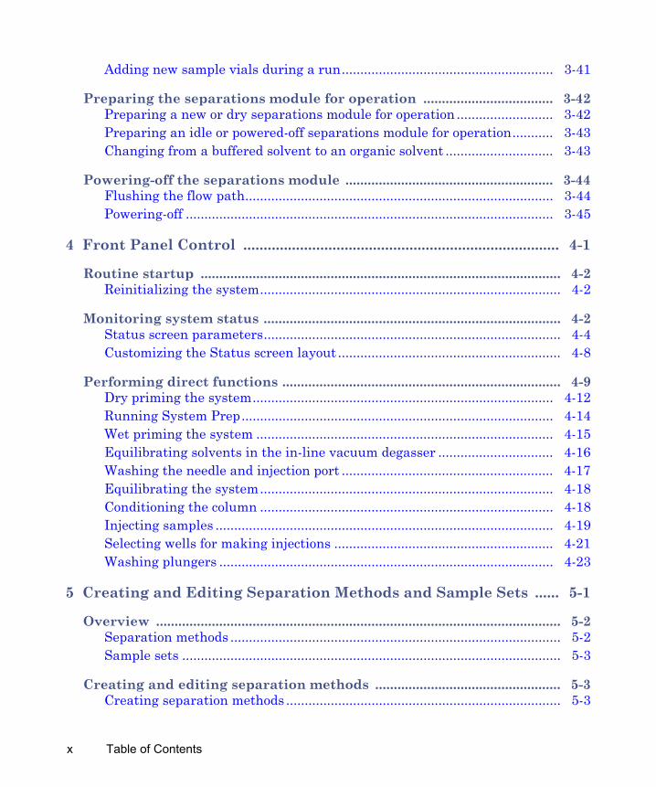
Plunger seal-wash systemThe seal-wash solvent lubricates the plunger and flushes away any solvent or dried salts forced past the plunger seal from the high pressure side of each piston chamber. Washing the seals extends their life.
The plunger seal wash system operates as follows:
1. Plunger seal wash solvent flows from a reservoir to the solenoid wash pump and then to a cavity behind the main plunger seal in the primary head.
2. The solvent flows from the head and into the cavity behind the plunger seal, in the accumulator head.
3. From the accumulator head, the solvent flows to waste.When the solvent management system is delivering solvent, the plunger seal wash pump intermittently circulates the wash solvent according to a time that you specify.
Preferred plunger stroke volumeThe separations module’s discrete, programmable stroke volumes provide optimal flow delivery and solvent blending. Nevertheless, you can improve performance for specific applications by overriding the default (preprogrammed) stroke volume of 130 µL. To do so, you select a preferred stroke volume of 25 µL, 50 µL, or 100 µL, as shown in the following table. A larger stroke volume can be more effective with solvents that require additional mixing, like trifluoroacetic acid [TFA] gradients. This additional mixing, unlike static or dynamic mixing, occurs without added delay volume.
Alternate stroke volumes
Flow range (mL/min) Stroke volume (µL)0.050 - 0.530 250.531 - 1.230 501.231 - 3.030 1003.031 - 5.000 130
Solvent management system overview 1-7

In-line vacuum degasserThe separations module’s PerformancePlus in-line vacuum degasser features five vacuum degasser chambers enabling you to degas eluents A, B, C, and D as well as the purge solvent.The in-line vacuum degasser combines a variable speed, continuously operating vacuum pump with low-internal-volume degasser chambers. The result of this design is shortened instrument priming and equilibration times, and minimum delay when resuming operation from an idle state or following a solvent change. The degasser’s vacuum pump is designed specially for membrane degassing of HPLC mobile phases. The continuously running pump provides rapid vacuum pull-down at high speed and consistent vacuum level at low speed.
Degasser considerations
Degassing efficiency is based on the solvent gas load and the length of time that the solvent remains in its vacuum chamber. Gas removal efficiency decreases as the solvent flow rate increases because the solvent is in the vacuum chamber for less time. Adopting a normal analytical flow rate range of 0.000 to 5.000 mL/min, the degasser removes most of the dissolved gasses. Because you can perform dry and wet priming at flow rates greater than 5.000 mL/min, you must expose the solvents to the degasser vacuum for a short time (after priming) at zero flow rate (see “Equilibrating the system” on page 4-18).
Vacuum degasser pressure transducers
The separations module is equipped with an absolute pressure transducer (APT), which is unaffected by altitude or barometric changes. The following table lists its attributes.
Absolute pressure transducer attributes
Item Absolute pressure transducerUnits displayed kPa, bar, psia Sign of displayed unit PositiveTheoretical maximum vacuum (based on 1 atm at sea level)
0 psia
1-8 Introduction to the Waters e2795 Separations Module

Sample management system overview
The sample management system holds and positions sample plates and injects samples into the solvent flow. It can accommodate as many as four sample plates of varying capacities. The system allows you to combine different types of sample plates and vial holders during a sample run. The plate carrier moves the plates to the injection station in the sample compartment.Five valves, two pumps, and a syringe control the flow of sample, purge solvent, and needle-wash solvent. The five valves are designated inject, waste, bypass, wash, and purge. The two pumps are designated drain and wash.
Operating range (using the default vacuum pressure threshold)
22.1 to 0 kPa (0.2 to 0 bar, 3.2 to 0 psia) (If pressure is out of range, an asterisk (*) appears in the pressure field.)
“Typical” value 9.7 to 13.8 kPa (0.1 to 0.14 bar, 1.4 to 2.0 psia)
More vacuum Smaller number is displayed
Absolute pressure transducer attributes (Continued)
Item Absolute pressure transducer
Sample management system overview 1-9

Flow path through the sample management system
Holding loop
Waste valve
Waste
Syringe
Purge valve Wash valve
X-Y-Z mechanism
Vacuum degasser
Needle wash pump
Needle wash solvent reservoir
Purge solvent reservoir
18
7
65
4
2Bypassvalve
Sample needle(draw)
Sample plate
Wash station
Drainpump
Inlet from solvent management system
Outlet to column
Inject valve
Sample loop
Loadposition
Injectposition
Sample needle(load)
Primeposition
Waste
Waste
Waste
Wash overflow (to waste)
1-10 Introduction to the Waters e2795 Separations Module

The mobile phase and wash solvent paths through the sample management system vary according to which of these procedures is being performed:
• Loading a sample – The Load position of the injection valve isolates the sample loop from the solvent flow path to the column and allows solvent to flow through the injection valve to the column.
• Injecting a sample – The Inject position of the injection valve connects the sample loop to the solvent flow. Two types of injection are available, full loop and partial loop.For each injection type, the system provides one or more of these user-programmable needle-wash and purge cycles to ensure that each injection is free from sample residue:– For Needle Wash – The wash cycle washes the interior and exterior
of the sample needle and drains excess solvent from the sample management system. This cycle is user-selectable and is recommended for optimum carryover performance.
– For Purge – The wash cycle includes a purge that draws the purge solvent through the in-line vacuum degasser, and then through the needle and the injection valve, ensuring a clean degassed flow path for each injection. The replacement volume is user-selectable and is recommended for optimum system performance.
• Bypassing solvent flow – During priming of the solvent management system and during rapid equilibration, solvent flows through a bypass valve to waste.
Sample management system features
Parallel processing
The sample management system offers an advantage over traditional (sequential) chromatography cycle times by performing chromatographic operations in parallel. Parallel processing maximizes throughput by minimizing cycle time. While one sample is running, you can specify that a second sample be drawn and injected immediately after the preceding injection is completed or while the current sample is being injected. You can also specify that the sample be drawn and pre-loaded into the injector while the current separation is being completed.
Sample management system overview 1-11

Parallel processing with rapid equilibration
The system also provides for rapid equilibration by switching the column off-line, purging the system at a high flow rate, and then loading the next sample during column reequilibration. By using parallel processing with rapid equilibration, you can significantly increase throughput for some applications.For more information on parallel processing, see “Setting up for high-throughput operation” on page 6-9.
Sample pooling
The system allows you to pool samples, that is, to collect aliquots from two or more samples, “pool” them in the sample loop, and then inject the pooled sample after a specified period of time. For more information on Sample Pooling, see “Specifying the Pool function” on page 5-54.
Sample management system componentsTip: Waters recommends you consult the table on page C-6 before configuring plates for the separations module.
XYZ needle assembly
The three-axis (XYZ) needle assembly of the separations module sample management system can process samples from up to four of any of the following types of sample plates:
• 24-position rectangular vial-holder plates, for 2-mL autosampler vials or for 1.5-mL microcentrifuge (Eppendorf®-style) tubes
• 48-position rectangular vial-holder plates for use with these items:– 2-mL autosampler vials (6 rows × 8 columns)– 0.50-mL microcentrifuge (Eppendorf-style) tubes (8 rows × 6
columns)• 96-well microtiter sample plate (tall and standard)• 384-well microtiter sample plate• Open access plates (see “Open access plates” on page 1-26)
You can customize any of the standard plates as described in “Configuring plate types” on page 3-19.
1-12 Introduction to the Waters e2795 Separations Module

Restrictions:• Use of plates with adhesive-backed sealing foils and films can interfere
with the operation of the needle and injection port.• To avoid damaging the needle or XYZ mechanism, do not use vial caps
less than 8.8 mm OD.The three-axis (XYZ) sampling mechanism uses opto-sensors to detect the depth of the first sample well or vial in a sample set or list, or you can specify the well depth. Use of pre-slit septa and non-adhesive-backed sealing foils or film prevents needle coring and degradation.
XYZ Needle assembly mechanism
Plate carrier
The rotating sample plate carrier holds as many as four plates that meet these specifications: 128-mm × 86-mm (5-inch × 3 3/8-inch) with a maximum height of 48.2 mm (1.9 inches).
Caution: To prevent damage to the needle, do not use plate covers made of hard or thick material.
Sample management system overview 1-13
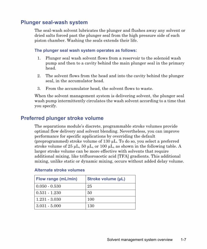
The plate carrier is locked into place under the X-Y field of operation. Each plate is dynamically held in position on the carrier by a plate-positioning spring that engages the plate as it moves into the sampling position.For information on loading the sample plates and plate carrier, see “Loading the sample plates” on page 3-38.For information on maintenance of the sample plate carrier, see “Cleaning the sample compartment and plate carrier” on page 7-46.For information on editing well locations on the e2795 Separations Module front panel, see “Selecting wells for making injections” on page 4-21.
Sample plate carrier
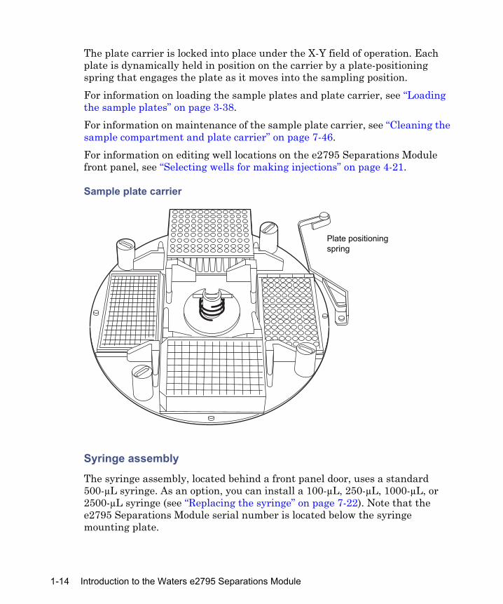
Syringe assembly
The syringe assembly, located behind a front panel door, uses a standard 500-µL syringe. As an option, you can install a 100-µL, 250-µL, 1000-µL, or 2500-µL syringe (see “Replacing the syringe” on page 7-22). Note that the e2795 Separations Module serial number is located below the syringe mounting plate.
�����
Plate positioning spring
1-14 Introduction to the Waters e2795 Separations Module
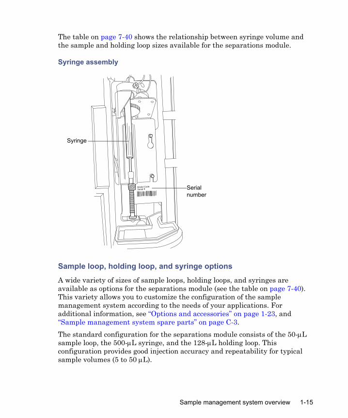
The table on page 7-40 shows the relationship between syringe volume and the sample and holding loop sizes available for the separations module.
Syringe assembly
Sample loop, holding loop, and syringe options
A wide variety of sizes of sample loops, holding loops, and syringes are available as options for the separations module (see the table on page 7-40). This variety allows you to customize the configuration of the sample management system according to the needs of your applications. For additional information, see “Options and accessories” on page 1-23, and “Sample management system spare parts” on page C-3.The standard configuration for the separations module consists of the 50-μL sample loop, the 500-μL syringe, and the 128-μL holding loop. This configuration provides good injection accuracy and repeatability for typical sample volumes (5 to 50 μL).
Syringe
Serial number
Sample management system overview 1-15

When you want to optimize for a certain aspect of your chromatography (for example, volume repeatability, cycle time, or injection-volume accuracy), you can use other combinations of syringe, sample loop, and holding loop, according to the following guidelines:
• If you can, use the sample loop size as your first choice to achieve a desired performance characteristic that the standard configuration cannot achieve. The sample loop size is the most versatile configurable option.
• Improve the repeatability of small (for example, 5-μL) injections over the standard configuration performance by following these procedures:– Installing a smaller sample loop and using the full-loop injection
mode (see the table on page 5-46).– Installing a smaller sample loop and a smaller-volume syringe (see
the table on page 7-40). The smaller syringe decreases the significance of syringe-drive variability but also adds to cycle times by requiring more syringe draws (5 to 10) to purge the needle wash solvent from the needle and holding loop.
• Optimize cycle time by installing a larger (for example, 2500-μL) syringe. Because less than one stroke of the large syringe purges the needle and holding loop, the cycle time is greatly reduced. Although this configuration increases the significance of syringe drive variability, and therefore the variability in injection volumes, using the full-loop injection mode can help to keep variability minimal.
• Make large-volume injections by installing a larger sample loop, a larger syringe, and a holding loop of compatible size (see the table on page 7-40). Ensure that the sample size does not exceed the capacity of the holding loop. If it does, the sample can contaminate the syringe and the rest of the sample management system.
Operating configurations
The separations module can operate in three general control modes:• System Controller• No Interaction • Remote Control
Both System Controller and No Interaction are standalone modes.
1-16 Introduction to the Waters e2795 Separations Module

System Controller modeIn this standalone mode, the separations module functions as the HPLC system controller. You can perform runs manually or programmatically in the System Controller mode. For a manual run, you input parameter values and selections via the front panel of the separations module. For an automatic run, you use separation methods, sample sets and/or sample templates to control the separations module. See Chapter 4 for information on using the front panel to control runs. See Chapter 5 for procedures to create and store separations methods, sample sets, and sample templates.Depending on your system components, you can connect the separations module to other components via these:
• IEEE-488 (digital) signal connections for Waters detectors• I/O (analog) signal connections (hard wire cables)• RS-232 (digital) signal connections for printers or integrators
Follow the procedures in Chapter 4 to control the HPLC system in the System Controller mode.Requirement: In System Controller mode, the separations module cannot control any other instruments/detectors via Ethernet communications. You can use Ethernet communications only when the separations module is configured for remote control (see “Remote control mode” on page 1-19).
Digital signal connections for system controller operation
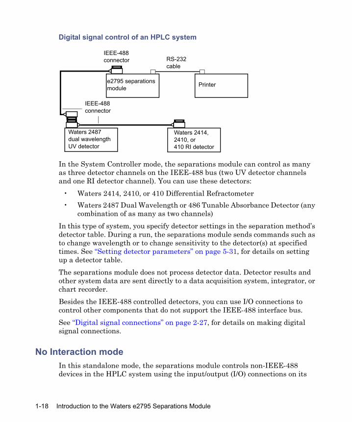
The following figure illustrates a typical HPLC system configuration where the separations module (in System Controller mode) uses only IEEE-488 and RS-232 digital signal connections to control the HPLC system components.
Operating configurations 1-17
Digital signal control of an HPLC system
In the System Controller mode, the separations module can control as many as three detector channels on the IEEE-488 bus (two UV detector channels and one RI detector channel). You can use these detectors:
• Waters 2414, 2410, or 410 Differential Refractometer• Waters 2487 Dual Wavelength or 486 Tunable Absorbance Detector (any
combination of as many as two channels)In this type of system, you specify detector settings in the separation method’s detector table. During a run, the separations module sends commands such as to change wavelength or to change sensitivity to the detector(s) at specified times. See “Setting detector parameters” on page 5-31, for details on setting up a detector table. The separations module does not process detector data. Detector results and other system data are sent directly to a data acquisition system, integrator, or chart recorder. Besides the IEEE-488 controlled detectors, you can use I/O connections to control other components that do not support the IEEE-488 interface bus.See “Digital signal connections” on page 2-27, for details on making digital signal connections.
No Interaction modeIn this standalone mode, the separations module controls non-IEEE-488 devices in the HPLC system using the input/output (I/O) connections on its
e2795 separations module
Waters 2487dual wavelength UV detector
Waters 2414,2410, or 410 RI detector
Printer
IEEE-488connector
RS-232cable
IEEE-488connector
1-18 Introduction to the Waters e2795 Separations Module

rear panel. This mode disconnects the separations module from the IEEE-488 bus and Ethernet interface. Use it when you want to suspend communications with a connected Empower system or Millennium workstation, and operate system components from their front panels.
Input/output (I/O) signal connections for No Interaction mode
The following figure shows an example HPLC system configuration where the separations module controls the HPLC components through I/O signal connections.
I/O signal control of an HPLC system
In this type of system, you set up each HPLC component individually via its front panel. You connect the components to the separations module using the I/O connector on its rear panel. During a run, I/O signals from the separations module trigger synchronized or timed events in all the HPLC components. The separations module does not process detector data. Detector results and other system data go directly to a data acquisition system, integrator, or chart recorder. See “I/O signal connections” on page 2-23, for details on making I/O signal connections.
Remote control modeIn remote control mode, the separations module and the other HPLC system components are controlled by one of these data systems:
• Empower Chromatography Data Software
• Waters Millennium Chromatography Manager • Waters MassLynx Mass Spectrometry Software for mass spectrometers
e2795separations module
I/O cables
Detector
ChartrecorderAnalog data
Operating configurations 1-19

• RS-232 communications by non-Waters data systems• An external autosampler (the Waters 2700 Sample Manager, for
example) with the separations module in the Operate Gradient by Event In mode.
Use the procedures in Chapter 6 to set up the separations module for remote control.
Supported IEEE-488 and Ethernet configurations
For remote control, you can configure the separations module for IEEE-488 and Ethernet communications only when it is configured as follows:
• The separations module and detector(s) communicate with the data system via IEEE-488
• The separations module and detector(s) communicate with the data system via Ethernet
• The separations module and data system communicate via IEEE-488, and include one or more detectors that can communicate with the data system only via Ethernet (that is, a Waters 2998, 2489, 2475, 2424, e-SAT/IN module-connected, or mass spectrometer: for example, 3100) detector
Empower control
The following figure illustrates a typical HPLC system using Ethernet communications and Empower 2 Chromatography Data Software.
Typical e2795 Separations Module HPLC system under Empower 2 software control
e2795 separations module
2489, 2998, 2475, 2424, or 2414 detector
Ethernet switch
Empower 2system
Ethernet connections
1-20 Introduction to the Waters e2795 Separations Module
The separations module can communicate with Empower software via Ethernet (such as with Empower 2, feature release 5) or via the IEEE-488 interface bus (but not both simultaneously). Use Empower software to create instrument methods and method sets to control the separations module and other HPLC system components. See the Empower software documentation for more information on creating instrument methods and method sets.
Millennium control
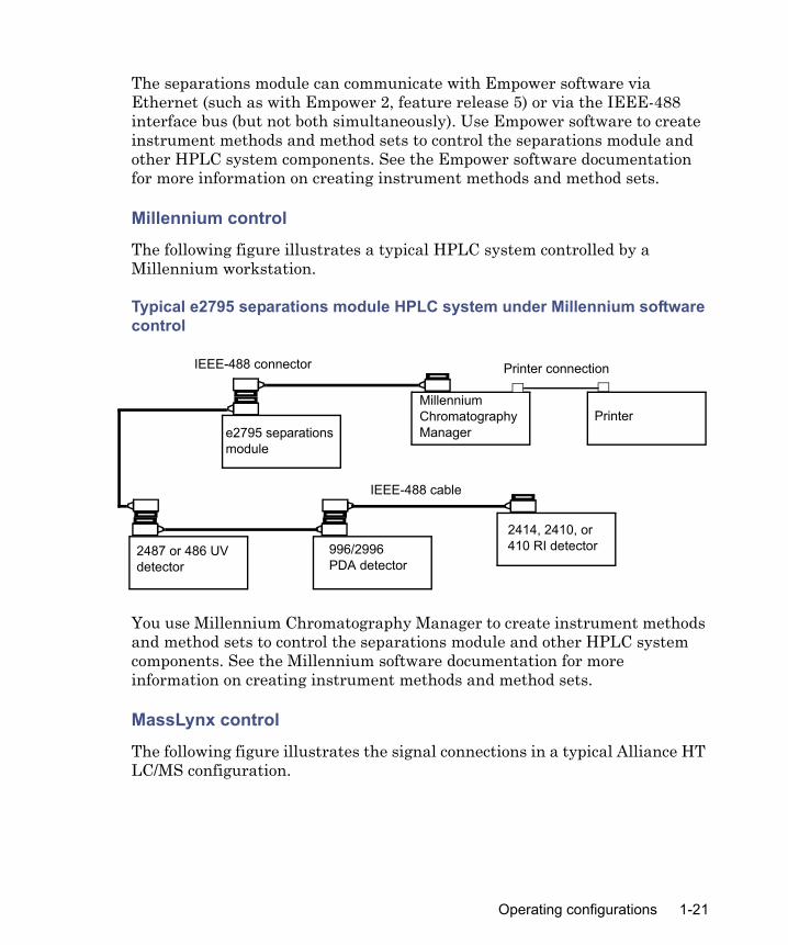
The following figure illustrates a typical HPLC system controlled by a Millennium workstation.
Typical e2795 separations module HPLC system under Millennium software control
You use Millennium Chromatography Manager to create instrument methods and method sets to control the separations module and other HPLC system components. See the Millennium software documentation for more information on creating instrument methods and method sets.
MassLynx control
The following figure illustrates the signal connections in a typical Alliance HT LC/MS configuration.
996/2996PDA detector
2487 or 486 UV detector
e2795 separations module
Millennium Chromatography Manager
Printer
2414, 2410, or 410 RI detector
Printer connection
IEEE-488 cable
IEEE-488 connector
Operating configurations 1-21

Typical Alliance HT LC/MS system under MassLynx software control
When you control the separations module with MassLynx Mass Spectrometry Software, you use the MassLynx inlet editor to define operating parameters for the separations module and detector(s)—but not the mass spectrometer—used in the LC/MS system. See the MassLynx software documentation for more information on controlling the separations module.
RS-232 control
To set parameters that remotely control the separations module from a data system that uses RS-232 communications, refer to the data system’s documentation.
Operate Gradient by Event In control
In Operate Gradient by Event In mode, the separations module is connected to an external autosampler (a Waters 2700 Sample Manager, for example). In this mode, the separations module provides gradient functionality, and the external autosampler provides the sampling/injection functionality. The external autosampler, which is connected to the I/O signal connector on the separations module’s rear panel, signals the solvent management system to begin a gradient.
ZQ or other mass spectrometer
2487 or 996/2996 detector
e2795 separations module
MassLynx data system Printer
MassLynx proprietary interface cable
Printer connection
IEEE-488 cable
IEEE-488 connector
Inject start
1-22 Introduction to the Waters e2795 Separations Module

Options and accessories
Various options for the separations module are available to suit your applications and site requirements. You can display a list of the hardware options currently installed in your separations module by pressing the Configuration screen’s Options key. See “Configuring the separations module” on page 3-10, for details on displaying the Configuration screen.
Sample heater/coolerTo optimize sample stability and/or solubility, the sample heater/cooler maintains the sample compartment at temperatures from 4 °C to 40 °C. The set point temperature can range, in 1 °C increments, between 4 °C (or the ambient temperature less 25 °, whichever is greater) to 40 °C. The sample heater/cooler is installed on the separations module at the factory or on site by Waters personnel. The heater/cooler, which uses four Peltier devices for temperature control, is mounted through the separations module’s rear panel.
Column heaterThe column heater maintains the column at temperatures between 5 °C above ambient (minimum of 20 °C) to 65 °C. An alarm warns you when the temperature varies outside the range that you specify. The Waters Alliance Series Column Heater and Column Heater/Cooler Operator’s Guide presents the procedures for installing, operating, maintaining, and basic troubleshooting of the Alliance® column heaters and column heater/coolers.
Column heater/coolerThe column heater/cooler maintains the column at temperatures between 4 °C and 65 °C. The set point temperature can range, in 1 °C increments, between 4 °C (or the ambient temperature less 15 °, whichever is greater) to 65 °C. The Waters Alliance Series Column Heater and Column Heater/Cooler Operator’s Guide presents the procedures for installing, operating, maintaining, and basic troubleshooting of the Alliance® column heaters and column heater/coolers.
Options and accessories 1-23
SyringesYou can remove the standard 500-µL syringe and install a 100-µL, 250-µL, 1000-µL, or 2500-µL sample syringe. For more information, see “Sample loop, holding loop, and syringe options” on page 1-15 and “Replacing the syringe” on page 7-22.
Holding loopsYou can replace the installed 128-µL holding loop with a 500-µL or 3000-µL loop. For more information, see “Sample loop, holding loop, and syringe options” on page 1-15 and “Replacing the holding loop” on page 7-40.
Sample loopsYou can replace the standard, 50-µL, sample loop with a larger (100-µL, 200-µL, 500-µL, or 2000-µL) or smaller (5-µL or 20-µL) loop to inject full-loop sample volumes other than 50 µL. For more information, see “Sample loop, holding loop, and syringe options” on page 1-15 and “Replacing the sample loop” on page 7-43.
Column selection valvesThe motorized column selection valve enables the system to switch solvent flow to one of several columns. It is usually mounted in the column heater or column heater/cooler (see the figure on page 1-25). The valve is factory-installed or can be installed on site as an add-on option.The separation module has these column selection valve options:
• 3-column• 6-column• Column regeneration
1-24 Introduction to the Waters e2795 Separations Module
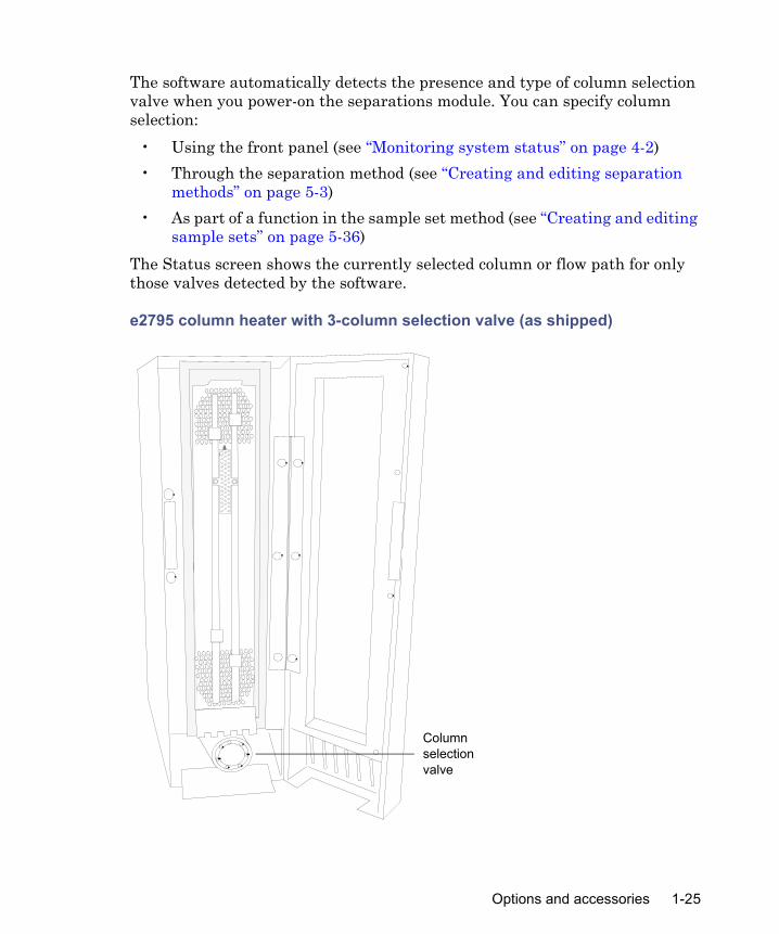
The software automatically detects the presence and type of column selection valve when you power-on the separations module. You can specify column selection:
• Using the front panel (see “Monitoring system status” on page 4-2)• Through the separation method (see “Creating and editing separation
methods” on page 5-3)• As part of a function in the sample set method (see “Creating and editing
sample sets” on page 5-36)The Status screen shows the currently selected column or flow path for only those valves detected by the software.
e2795 column heater with 3-column selection valve (as shipped)
Column selection valve
Options and accessories 1-25
Three-column selection valve
You use the 3-column selection valve to select any of three column positions. The 3-column selection valve is preconfigured before shipment, but you can reconfigure it. For more information, see “Connecting the column-selection valve” on page 2-16.
Six-column selection valve
You use the 6-column selection valve to select any one of six column positions, and you can specify any position as bypass or waste. For more information, see “Connecting the column-selection valve” on page 2-16.
Column regeneration valve
You use the column regeneration valve to perform LC operations using one column while the second column undergoes regeneration by a second solvent delivery system. For more information, see “Connecting the column-selection valve” on page 2-16.
Open access platesThe Waters Open Access Plate Kit (part number 200000114) consists of four 24-well plates (for 2-mL vials) that are beveled to allow access to the sample wells without removing the plates from the carrier. The plates are color-coded (blue, yellow, red, and green) to match the colors on the sample carrier and in the Open Access software option for Empower or Millennium32 software. Open access plates help you place the sample vials in the correct locations. For more information, see “Loading the sample plates” on page 3-38.A High-Capacity Open Access Kit (part number 200000123) is available with color coding. Each of its four plates has 48 vial positions.
1-26 Introduction to the Waters e2795 Separations Module

2 Installing the e2795 Separations Module
Contents
Topic PageInstallation overview 2-2Unpacking 2-4Connecting to the electrical power supply 2-6Installing the column heater and column heater/cooler 2-7Connecting tubing and attachments 2-8Performing signal connections 2-21
2-1
Installation overview
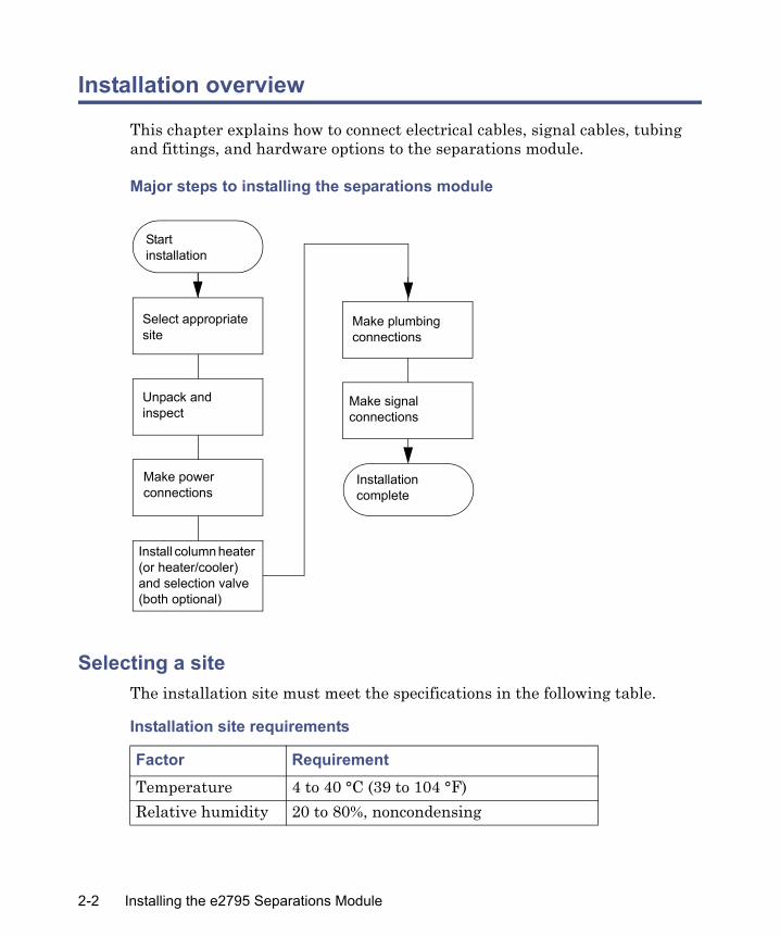
This chapter explains how to connect electrical cables, signal cables, tubing and fittings, and hardware options to the separations module.
Major steps to installing the separations module
Selecting a siteThe installation site must meet the specifications in the following table.
Installation site requirements
Factor RequirementTemperature 4 to 40 °C (39 to 104 °F)Relative humidity 20 to 80%, noncondensing
Startinstallation
Installation complete
Select appropriate site
Unpack and inspect
Make signal connections
Make plumbing connections
Install column heater (or heater/cooler) and selection valve (both optional)
Make power connections
2-2 Installing the e2795 Separations Module
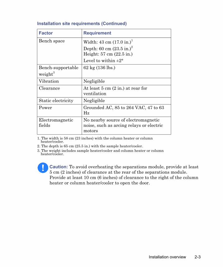
Bench space Width: 43 cm (17.0 in.)1
Depth: 60 cm (23.5 in.)2
Height: 57 cm (22.5 in.)Level to within ±2°
Bench-supportable weight3
62 kg (136 lbs.)
Vibration NegligibleClearance At least 5 cm (2 in.) at rear for
ventilationStatic electricity NegligiblePower Grounded AC, 85 to 264 VAC, 47 to 63
HzElectromagnetic fields
No nearby source of electromagnetic noise, such as arcing relays or electric motors
1. The width is 58 cm (23 inches) with the column heater or column heater/cooler.
2. The depth is 65 cm (25.5 in.) with the sample heater/cooler.3. The weight includes sample heater/cooler and column heater or column
heater/cooler.
Caution: To avoid overheating the separations module, provide at least 5 cm (2 inches) of clearance at the rear of the separations module. Provide at least 10 cm (6 inches) of clearance to the right of the column heater or column heater/cooler to open the door.
Installation site requirements (Continued)
Factor Requirement
Installation overview 2-3

Typical system dimensions for the e2795 separations module
Firmware and software requirementsThe Waters detectors that connect to the separations module must meet minimum firmware requirements to successfully communicate with the software installed in the separations module. Similarly, the external remote management system that controls the separations module must also meet minimum software requirements. See the Waters e2795 Separations Module Release Notes for details on minimum firmware and software requirements.
Unpacking
The separations module is shipped in a single carton on a wooden pallet. Save the carton and pallet in case you decide to transport the unit in the future. External accessories and options such as columns, column heater, and detectors are shipped in separate cartons.
TP01355
57 cm (22.5 inches)
43 cm (17 inches); 58 cm (23 inches) with column heater or column heater/cooler
60 cm (23.5 inches); 65 cm (25.5 inches) with sample heater/cooler
2-4 Installing the e2795 Separations Module

To unpack the separations module and its components:
1. Remove the bands securing each carton to the pallet.
2. Remove the cartons, the solvent bottle tray, the startup kit, and packing material.
3. Verify the contents of each carton against its packing slip.
4. Lift the separations module from the pallet, and place it at the site you have chosen for installation.
5. Remove the three, pink foam pieces used for packing.
6. Confirm that the instrument serial number (found in the syringe compartment below the syringe mounting plate) corresponds to the number on the structural integrity certificate.
7. Verify that the contents of the startup kit match the startup kit list. Tip: For Alliance HT systems operating under MassLynx software control, the MassLynx Data Acquisition Guide and the MassLynx User’s Guide are required; the MassLynx BioLynx & ProteinLynx User’s Guide and/or the MassLynx OpenLynx User’s Guide are optional.
8. Inspect all items for damage, and immediately report any shipping damage to both the shipping company and your Waters representative. Requirement: If shipping damage occurred, contact Waters Customer Service (see page iv). Refer to Waters Licenses, Warranties, and Support Services for complete information on shipping damages and claims.
Warning: To avoid injury, ensure that at least two persons lift the separations module from the pallet to the bench.
Unpacking 2-5
Connecting to the electrical power supply
The separations module automatically adjusts for AC input voltages in a continuous range from 85 to 250 VAC and 47 to 63 Hz.
To connect to the electrical power supply:
1. Ensure that the separations module is powered-off.
2. Connect the power cord to the connector on the rear panel (see the figure, below).
3. Connect the other end of the power cord to a properly grounded AC power supply. Requirement: Do not power on the separations module until you complete all tubing and signal connections.
Warning: Ensure the top cover and side panel are attached before you apply power to the separations module.
Caution: • To avoid damage to components, power-off the separations module
before you connect or disconnect the column heater or column heater/cooler cable.
• Do not power-on the separations module until you install the column heater or column heater/cooler and complete all tubing and signal connections.
• Proper operation of the separations module requires that the AC power supply be grounded and that it has no abrupt voltage fluctuations.
2-6 Installing the e2795 Separations Module

Rear panel of the separations module
Installing the column heater and column heater/cooler
The Alliance-series column heater or column heater/cooler is mounted on the separations module’s right-hand side-panel using three screws. A connector on the rear panel of the separations module provides power and signal connections to the column heater or column heater/cooler. Refer to the Waters
Caution: • To avoid possible damage to components, power-off the separations
module before you connect or disconnect the column heater or column heater/cooler cable.
• Before you can install the column heater or column heater/cooler, remove the separations module’s right-hand side panel to access and remove the foam restraints securing the X-Y-Z needle assembly in the shipping position.
Column heater or column heater/cooler connector
I/O connectors
RS-232 connector
Ethernet connector
IEEE-488 connector
Power connector
Installing the column heater and column heater/cooler 2-7

Alliance Series Column Heater and Column Heater/Cooler Operator’s Guide for procedures for installing, operating, maintaining, and basic troubleshooting of the column heater and column heater/cooler.
Connecting tubing and attachments
Required materials• Razor blade or tubing cutter• 3/16-inch ID tubing • 3/16-inch barbed fitting, if installing the detector drip tray• 90° elbow, 2 each• 0.005-inch ID tubing • Purse clips
Tip: All of the items above except for the razor blade or tubing cutter are provided in the startup kit.The following figure is a schematic representation of the separations module’s tubing connections. As such, it does not show how the tubing is routed.
2-8 Installing the e2795 Separations Module

e2795 separations module fluidic connections (functional diagram)
Installing the detector drip and solvent bottle traysIf you want to position the detector atop the separations module, mount the detector drip tray (see the figure on page 1-2) at the front of the separations module’s top panel.
To connect the drip tray outlet:
1. Cut a piece of 3/16-inch ID tubing (startup kit) to a length of about 25 cm (10 inches).
2. Press the 3/16-inch barbed fitting (startup kit) into the drain hole in the bottom of the drip tray.
e2795separationsmodule
Plunger-seal-wash solventPurge solvent*
Solvent D*
Sol
vent
C*
Sol
vent
B*
Solv
ent A
*
Needle-wash waste (3/8-inch clear tubing)
Degasser vent (1/4-inch tubing routed to fume hood)
Plunger-seal-wash waste (1/8-inch clear tubing)
Red line(to column orcolumn selectionvalve)
Needle-wash Gre
en
Cle
ar
Gre
en Note: Needle wash, plunger-seal wash, and purge solvent can be the same.
*Internally degassed
A B C D
solvent
Connecting tubing and attachments 2-9

3. Attach one end of the tubing you cut to the fitting on the bottom of the detector drip tray.
4. Remove the backing from the adhesive pads on the bottom of the detector drip tray.
5. Open the syringe access door.
6. Pass the free end of the tubing through the hole in the top panel and into the syringe compartment.
7. Position the free end of the tubing on the drip tray below the syringe compartment.
8. Mount the drip tray so that the adhesive pads adhere to the top cover of the separations module.
9. Mount the solvent bottle tray atop the separations module’s left-hand side.
Installing solvent supply tubingThe tubing from the separations module to the solvent reservoirs is coiled and stored behind the separations module. One end of the solvent tubing is connected (at the factory) to the in-line vacuum degasser, which is in turn connected to the gradient proportioning valve (GPV).Each tube is marked with a letter (corresponding to each solvent reservoir) and a color-coded label.
Caution: To ensure proper drip protection, verify the retaining screws in the solvent delivery and solvent conditioning trays are tightened before you operate the system.
Solvent supply tubing identification
Solvent line label
Solvent line color
A YellowB BlueC RedD GreenPurge solvent Green
2-10 Installing the e2795 Separations Module
To install the solvent lines:
1. Uncoil the solvent lines stored behind the separations module.
2. Remove the filter from each solvent line, and insert the free end of each solvent line through a reservoir cap (startup kit).
3. Reinstall a filter on the end of each solvent line.
4. Install each reservoir cap on the appropriate reservoir. Requirement: Make sure the solvent line extends to the bottom of the reservoir.
Recommendations for solvent reservoirs
• You can place as many as four 1-L reservoirs and one 250-mL reservoir in the solvent bottle tray.
• To maintain adequate solvent head pressure and ensure proper solvent delivery, position the solvent reservoirs above the level of the solvent management system, at least 20 inches above the laboratory bench.
• To prevent solvent overflow, do not use pressurized solvent reservoir bottles. Pressures above 5 psi can force solvent through the internal components of the gradient proportioning valve (GPV), possibly causing a spillover into the solvent waste reservoir or an adverse mixture with other solvents in the GPV.
Installing the degasser vent tubing
Besides removing dissolved gases from the solvents, the degasser draws away solvent vapors, which can condense to form droplets in the exhaust system. The degasser exhausts these gases and droplets, if any, through a vent line.To install the degasser vent tubing, place the free end of the tubing (the clear, 1/8 × 1/4-inch tubing that exits the rear of the instrument) in a waste container located in a properly functioning fume hood.Requirement: When your installation requires exhausting the degasser vent line at a vertical height higher than that of the vent line exiting the rear of the separations module, route the first 30.5 cm (1 ft) of vent line at the instrument
Warning: To avoid exposure to solvent vapors, connect the degasser exhaust tube to a suitable fume hood. Check local building and health codes for specific requirements regarding the venting of solvent vapors.
Connecting tubing and attachments 2-11

bench height before extending it upward to the fume hood. This requirement will help to minimize the risk of condensation bleeding back to the vacuum pump. Additionally, if your HPLC application involves the use of volatile solvents with no or very low flow for long periods, you can tee a solvent trap into the vent line to collect the small amount of condensation formed near the unit.
Making waste line connectionsRequirements:
• Perform the waste line connections for spill tray, sample compartment, needle wash and plunger-seal wash before operating the separations module.
• Ensure all drain lines inside and outside the instrument are properly connected and unrestricted by obstructions or bends.
• The two main drain lines exiting the front of the instrument must lay flat on the bench top without allowing any upward travel.
• Direct the two main drain lines to an appropriate waste container of a volume equal to or greater than that of the combined volume of all solvent reservoirs.
• Maintain the waste container at a level lower than the instrument. • Always inspect the drain lines after moving or performing maintenance
on the instrument.
Caution: To maintain proper vacuum system operation, do not allow the vent line to become submerged. Do not allow the degasser vent tubing inside the solvent waste reservoir.
Caution: Failure to properly perform waste line connections can result in damage to the bench or adjacent instruments in the event of a solvent leak.
2-12 Installing the e2795 Separations Module

Proper waste tube configuration
Spill tray waste line
The spill tray waste outlet is located under the front panel of the separations module, below the solvent conditioning tray access door.
To install the spill tray waste line:
1. Cut a length of 3/16-inch ID tubing (startup kit) long enough to reach from the spill tray waste outlet to the front of the bench.
2. Connect one end of the tubing you cut in step 1 to the spill tray waste outlet.
3. Install a 90° elbow (startup kit) on the other end of the tubing.
4. Cut another length of 3/16-inch ID tubing long enough to reach from the elbow fitting to the waste reservoir.
5. Connect the tubing you cut in step 4 between the elbow and the waste reservoir.
Connecting tubing and attachments 2-13

Sample compartment waste line
The condensation waste outlet from the sample compartment is also located under the front panel of the separations module, to the right of the spill tray waste outlet. Spills from sample plates and condensate from the sample heater/cooler drain through this waste outlet.
To install the condensation waste line:
1. Cut a length of 3/16-inch ID tubing (startup kit) long enough to reach from the condensation waste outlet to the front of the bench.
2. Connect one end of the tubing you cut in step 1 to the condensation waste outlet.
3. Install a 90° elbow (startup kit) on the other end of the tubing.
4. Cut another length of 3/16-inch ID tubing long enough to reach from the elbow fitting to the waste reservoir.
5. Connect the tubing you cut in step 4 between the elbow and the waste reservoir.
Needle wash waste line
The needle wash, purge (mobile phase), and bypass valve waste tubes are combined inside the separations module and flow into the clear, 3/8-inch plastic needle wash waste line (see the table on page 2-15). Route this tube to a waste reservoir located at least 20 inches below the bench level of the separations module so the solvent waste drains properly.
Plunger-seal-wash waste line
Place the plunger-seal-wash waste line (1/8-inch, clear) in a suitable waste container (see the table on page 2-15).
Installing the wash reservoirsThe separations module requires at least two wash reservoirs to supply the three wash lines:
• Needle wash• Purge• Plunger-seal wash
2-14 Installing the e2795 Separations Module

The tubing for the wash reservoirs is located behind the separations module’s rear panel. Each wash tube is labeled and/or color-coded as indicated in the table, below. The plunger-seal-wash inlet tube has a diffuser attached to one end.
To install the wash reservoirs:
1. Place the reservoirs a minimum of 20 inches above the laboratory bench.
2. Remove the diffuser from the needle wash inlet tube (labeled WASH SOLVENT), insert the tube through a reservoir cap, reinstall the diffuser at the end of the tube, and install the cap on the needle wash reservoir.
3. Remove the diffuser from the purge inlet tube (labeled PURGE SOLVENT), insert the tube through a reservoir cap, reinstall the diffuser at the end of the tube, and install the cap on the purge reservoir.
4. Remove the diffuser from the plunger-seal-wash inlet tube (clear, labeled SEAL WASH IN), insert the tube through a reservoir cap, reinstall the diffuser on the end of the tube, and install the cap on the purge/plunger seal-wash reservoir (the purge solvent and plunger seal wash solvent can be the same).
Caution: To prevent damage to the separations module, be sure to use solutions that are miscible with the mobile phase and with the sample diluent you are using. For more information, see Appendix D.
Needle wash, plunger-seal wash, and purge tube color codes
Wash tube Label Color code Outerdiameter
Needle wash inlet WASH SOLVENT Green tag 1/8 in.Purge inlet PURGE SOLVENT Green tag 1/8 in.Plunger-seal wash inlet
SEAL WASH IN Green tag 1/8 in.
Needle wash waste No label Clear 3/8 in.Plunger-seal wash waste
No label Clear 1/8 in.
Connecting tubing and attachments 2-15

Connecting the columnThe red outlet tubing of the sample management system, which connects to the column inlet, is located behind the right-hand side panel.When you are connecting the separations module to a column switching valve, connect the red outlet tubing to the valve inlet. When you are connecting the separations module to an external autosampler and configuring for operating in Operate Gradient by Event In mode, connect the red outlet tubing to the inlet of the autosampler.
To connect the column directly to the red outlet tubing:
1. Pass the red outlet tubing through the opening in the middle of the right-hand side panel.
2. Connect the red outlet tubing to the column inlet, and tighten the fitting.
Recommendation: To optimize results using microbore columns or high-throughput methods, replace the red outlet tubing with an appropriate length of 0.005-inch ID tubing.If the optional column heater (or column heater/cooler) is installed, see “Installing the column heater and column heater/cooler” on page 2-7 for instructions on connecting the outlet tubing to the column heater (or column heater/cooler).
Connecting the column-selection valveThese optional column selection valves switch the flow path among multiple columns:
• 3-column selection valve• 6-column selection valve• Column regeneration valve
2-16 Installing the e2795 Separations Module

Three-column selection valve
The 3-column selection valve is an eight-port, three-position valve preconfigured at the factory as follows:
• Port 1 – Routed to the column (a 2.1 mm × 50 mm column is supplied)• Port 2 – Routed to waste• Port 3 – Routed through a restrictor bypass to the detector
Three-column selection valve configuration (as shipped)
You can complete installation of the 3-column selection valve after you install the column heater or column heater/cooler (see “Installing the column heater and column heater/cooler” on page 2-7).
Required material
Open-end wrench, 5/16-inch
1′2′
3′
12
3
Column 1
Red linein
Out todetector
Waste
IN
OUT
Restrictor
Connecting tubing and attachments 2-17

To connect the 3-column selection valve to the fluid path of the sample management system:
1. Use the 5/16-inch wrench to connect the red line (from the e2795 injection valve) to the IN port on the column selection valve.
2. Use the tubing and fittings supplied with the 3-column selection valve to connect the OUT port of the column selection valve to the detector inlet.
3. Replace the stainless steel union shipped inside the column heater or column heater/cooler with the column.Tip: The column can be the one supplied with the valve, or it can be a different one.
4. Route the waste line (installed) from port 2 of the column selection valve through the hole in the bottom of the column heater or column heater/cooler to a suitable waste reservoir.
You can reconfigure the 3-column selection valve as appropriate for your application.
Six-column selection valve
The 6-column selection valve is shipped separately with a coil of 0.010-in PEEK® tubing, a 0.0025-inch ID restrictor tube, and Upchurch Sealtight™ fittings. Connect as appropriate for your application (see the figure on page 2-19).Tip: Any of the six column positions can be used for a restrictor or for waste, as in the three-column selection valve (see the figure on page 2-17).
2-18 Installing the e2795 Separations Module

Six-column selection valve connections (example)
Column regeneration valve
The column regeneration valve is shipped separately with a coil of 0.010-inch PEEK tubing, a 0.0025-inch ID restrictor tube, and Upchurch Sealtight fittings. Connect as appropriate for your application (see the figure, below). Contact Waters Technical Service for more information.
1′ 2′ 3′
123
56
4′
5′
6′
4
IN
OUT
Column 1Column 2
Column 3
Column 4
Res
trict
or
Red line In
Out to detector
Waste
Was
te
Connecting tubing and attachments 2-19
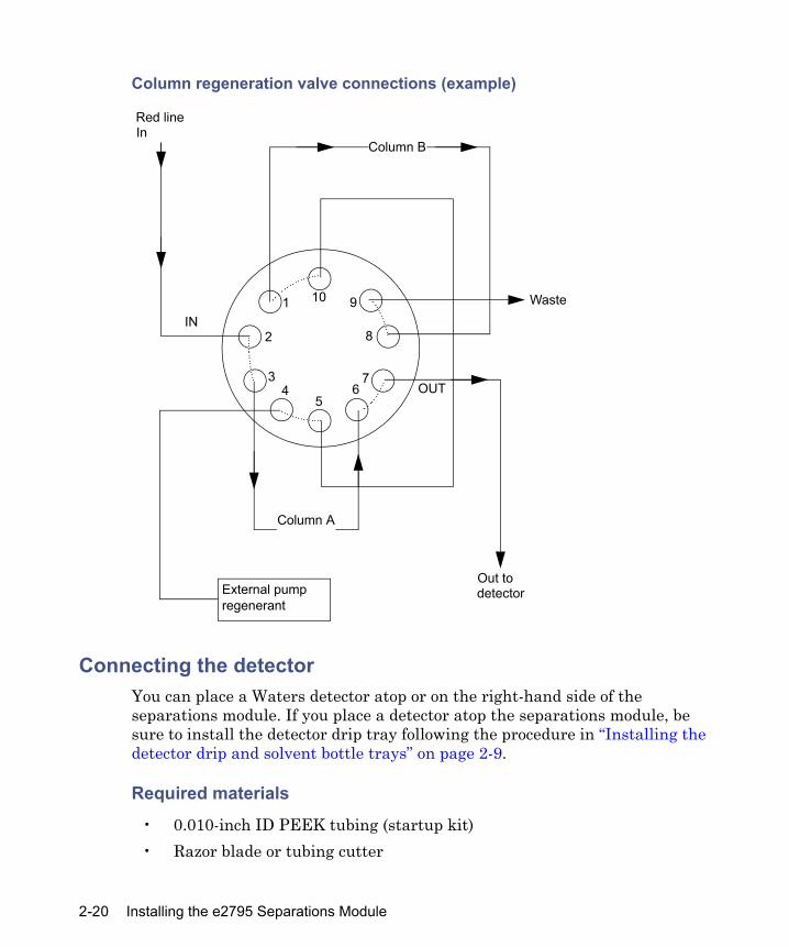
Column regeneration valve connections (example)
Connecting the detectorYou can place a Waters detector atop or on the right-hand side of the separations module. If you place a detector atop the separations module, be sure to install the detector drip tray following the procedure in “Installing the detector drip and solvent bottle trays” on page 2-9.
Required materials
• 0.010-inch ID PEEK tubing (startup kit)• Razor blade or tubing cutter
Column B
Column A
OUT
Waste
Out to detectorExternal pump
regenerant
IN
Red lineIn
1
2
34
56
7
8
910
2-20 Installing the e2795 Separations Module

• 3/16-inch ID tubing (startup kit)• Waste container
To connect the detector:
1. Cut a length of 0.010-inch ID tubing just long enough to reach from the column outlet to the detector inlet.Tip: To optimize results using microbore or high-throughput methods, Waters recommends that you replace the detector inlet tubing with an appropriate length of 0.005-inch ID tubing.
2. Connect the outlet of the column to the inlet of the detector with the tubing from step 1.
3. Connect the detector outlet to a suitable waste container with a length of 3/16-inch tubing.
Performing signal connections
The rear panel of the separations module provides connection terminals and communication ports for operation with external devices (see the figure on page 2-7).The signal connections you need to make to your separations module depend on these considerations:
• The operating mode you select for the separations module (System Controller, No Interaction, or one of the remote control modes)
• Types of instruments that make up your HPLC systemThis section describes the input/output (I/O) and digital signal connections that you can make from the terminal strips, RS-232 connectors, IEEE-488 bus connector, and Ethernet interface on the rear panel of the separations module.
Caution: To avoid spill damage, use a drip tray below the detector’s tubing connections.
Performing signal connections 2-21

Connecting signal cables
No
Yes
Start
Signal connections complete
No
YesConnect to RS-232valves or non-Waters data system?
Install RS-232 cable
No
Yes
Connect to non-IEEE, non-Ethernet detectoror an external auto-sampler?
Install event and I/O cable(s)
Connect to IEEE-488 bus?
Install IEEE-488 cable
Connect to Ethernet bus?
No
Yes Install Ethernet cable
2-22 Installing the e2795 Separations Module

I/O signal connectionsThe rear panel includes two removable connectors that hold the screw terminals for I/O signals. These connectors are keyed so that they can be inserted only one way.
I/O signal connectors
Caution: To avoid the risk of damaging other components, do not remove the keys in the A and B connectors. These keys ensure that the A connector fits only in the right-hand slot and the B connector only in the left-hand slot (when you face the rear panel).
Connector AConnector B
Inject Start
Stop Flow
Hold Inject 1
Hold Inject 2
Chart Out
Ground
Ground
Switch 1
Switch 2
Ground
Switch 3
Switch 4
Ground
Run Stopped
1
2
3
4+
5-
6+
7-
8+
9-
10
11
12
1
2
3
4
5
6
7
8
9
10
11
12
Performing signal connections 2-23

I/O signals
The following table describes the signals sent via the I/O connectors of the separations module. See Appendix B for information about the electrical specifications of each signal.
I/O signals
Signal DescriptionInject start An output (contact closure) to indicate that an injection
began.Connect a wire pair to the two Inject start terminals.
Stop flow An input that enables other LC components to stop the solvent flow from the separations module. You specify the signal conditions that stop the flow using the Events In screen key in the Configuration screen. Connect the positive input wire to the Stop Flow+ terminal and the negative input wire to the Stop Flow– terminal.
Hold inject 1 and 2 Inputs that enable other LC components to delay the injection (for example, an external autosampler used in the Operate Gradient by Event In mode or a fraction collector). You can specify the signal conditions (using the Events In screen key in the Configuration screen) that prevent the separations module from making an injection. Connect the positive input wire to the appropriate Hold Inject + terminal and the negative input wire to the appropriate Hold Inject – terminal.
2-24 Installing the e2795 Separations Module

The following table describes the parameter voltages for the chart out signals.
Chart out Outputs the analog signal (specified in the current separation method, or default separation method) to a device such as an integrator or strip chart recorder (see “Setting I/O parameter values” on page 5-27). You can select one of the following signals as the chart out signal:• Flow rate• System pressure• Primary head pressure• Composition (%A, %B, %C, %D)• Sample temperature• Column temperature• Column position• Degasser vacuum• Primary head pressureThe table below lists the output signal conditions for each of these parameters.
Switch 1–switch 4 See “Event switches” on page 2-26.Run stopped An output indicating that the separations module
ceased operating because of an error condition or operator request (pressing the Stop Flow button, for example).
Chart out signal conditions
Chart out signal Parameter setting at 0.1 V (minimum)
Parameter setting at 2.1 V (maximum)
Flow Rate 0.000 mL/min 10.000 mL/minSystem Pressure –344.7 kPa (–3.45 bar,
–50 psi)37,920 kPa (380 bar, 5500 psi)
Composition (%A, %B, %C, %D)
0.0 % 100.0 %
I/O signals (Continued)
Signal Description
Performing signal connections 2-25

Event switches
Switches 1 through 4 on connector A can serve as contact-closure switches to control column selection valves, fraction collectors, or similar external devices. Each pair of switch terminals (the two switch 1 terminals, for example) connects to an external device. You can operate the switches in either of two ways:
• Manually, from the Status screen• Automatically, in a separation method using the timed table in the I/O
screenSee “Setting I/O parameter values” on page 5-27 for information on using switches in an automated run. The following table describes the functions associated with each position of an event switch.
Sample Temperature
4 °C 40 °C
Column Temperature
0 °C 70 °C
Column position 0 32Degasser vacuum 0 psi 69 kPa (0.7 bar, 10 psi)Primary head pressure
–344.7 kPa (–3.45 bar, –50 psi)
34,474 kPa (344.7 bar, 5000 psi)
Event switch positions and functions
Position FunctionOn Closes the switchOff Opens the switchToggle Changes the current state of the switchPulse Closes or opens the switch for a user-defined
periodNo change Leaves the switch in its current state
Chart out signal conditions (Continued)
Chart out signal Parameter setting at 0.1 V (minimum)
Parameter setting at 2.1 V (maximum)
2-26 Installing the e2795 Separations Module

Digital signal connectionsThe rear panel includes one RS-232 interface connector, one IEEE-488 interface connector, and one Ethernet connector for digital signal communications (see “Rear panel of the separations module” on page 2-7).
RS-232 connections
The separations module is equipped with a DB-9 connector for RS-232-port communications (see “Rear panel of the separations module” on page 2-7). The RS-232 port supports both binary and ASCII communications. For remote operation, you use the RS-232 to connect to a non-Waters data system that uses RS-232 communications to control the separations module. To enable this communication, you choose Controlled via RS232 in the Configuration screen. For more information on the Configuration screen, see “Setting configuration parameters” on page 3-11.Alternatively, when the separations module is in the System Controller mode, you can use the RS-232 port to transmit data to external devices (a Waters 746 Data Module or serial printer, for example). You can transmit two types of data over this interface:
• Print Data – When you press the Print screen key• Report data – When a report is generated
The following table lists the values of the RS-232 output data parameters that you can select in the Configuration screen. For more information on the Configuration screen, see “Setting configuration parameters” on page 3-11.
RS-232 valves
The separations module allows you to control up to three external RS-232 valves using the RS-232 port. The system will scan for the valve type and
RS-232 output parameters displayed in the configurationscreen
Parameter ValueDevice None, 746 Integrator, RS232
Serial PrinterBaud rate 1200, 2400, 9600
Performing signal connections 2-27

address. For instructions on configuring the RS-232 valves, see “Configuring RS-232 valves” on page 3-24.Note: If you attach the RS-232 valves before powering-on the separations module, you do not need to configure the valves.
IEEE-488 connections
Use the IEEE-488 interface connector (see the figure on page 2-7) to connect the separations module to these IEEE-488 devices:
• Waters 2487, 486, 2414, 2410, and 410 detectors• BusLAC/E card in an Empower software system, a Millennium
workstation, a network LAC/E module (Millennium version 2.15 or later), or a LAC/E32 Acquisition Server (Empower or Millennium32 software)
• General purpose instrument board of a MassLynx computerRequirements:
• You cannot use the separations module’s IEEE-488 interface at the same time you are using its Ethernet port for communications.
• For remote control, you can configure the separations module for IEEE-488 communications only when it is configured as follows:• The separations module and detector(s) communicate with the data
system via IEEE-488• The separations module and data system communicate via
IEEE-488, and include one or more detectors that can communicate with the data system only via Ethernet (that is, a Waters 2998, 2489, 2475, 2424, e-SAT/IN module-connected, or mass spectrometer: for example, a 3100) detector (see “Supported IEEE-488 and Ethernet configurations” on page 1-20)
The IEEE-488 connector in the separations module mates with a standard IEEE-488 cable.
See the figure on page 1-18 for the signal connections (IEEE-488 and RS-232) in a typical HPLC system where the separations module functions as the
Caution: To avoid damaging components, power-off all instruments connected to the IEEE-488 bus before you connect an IEEE-488 interface cable to an instrument.
2-28 Installing the e2795 Separations Module

system controller. See “Empower control” on page 1-20 for a description of the signal connections used when the separations module functions under Empower software control. See the figure on page 1-21 for the signal connections in a typical HPLC system that includes a separations module under Millennium software control. See the figure on page 1-22 for the signal connections in a typical Alliance HT LC/MS configuration.
Setting the IEEE-488 address
From the Configuration screen, you can view or change the IEEE-488 address of the separations module. See “Configuring the operating mode” on page 3-25.
Ethernet connections
The separations module is equipped with a RJ-45 connector for Ethernet port communications (see the figure on page 2-7). The Ethernet port, a 10/100 Base-T interface, is used with the separations module configured for remote control, for example, when Empower 2 controls its operation. See the figure on page 1-20 for the signal connections in a typical HPLC system with a separations module and Empower Chromatography Data System.Requirements:
• You cannot use the separations module’s Ethernet port at the same time you are using its IEEE-488 interface for communications.
• For remote control, you can configure the separations module for Ethernet communications only when it is configured so that the separations module and detector(s) communicate with the data system via Ethernet (see “Supported IEEE-488 and Ethernet configurations” on page 1-20)
Tip: For help with HPLC Ethernet connections, you can order from Waters the Ethernet Switch Communications Kit (P/N: 700004123). The kit includes an 8-port Ethernet switch, cables, and a mounting bracket, for mounting the switch on the rear panel of the separations module or 1500 series HPLC pump. For additional Ethernet information, see the Waters Ethernet Instrument Getting Started Guide (P/N: 7150074403).As with IEEE-488 control, triggering of Waters Ethernet-controlled devices, such as 2489, 2998, 2414, and 2424 detectors, occurs over the Ethernet cable, and so requires no external I/O cables.Exception: Waters 2475 Fluorescence Detector, V2.02 requires an external I/O trigger cable under Ethernet control.
Performing signal connections 2-29

Configuring the Ethernet port
On the Configuration screen, select the operating mode, such as Empower, and then Auto/Ethernet from the Network Address box. See “Configuring the operating mode” on page 3-25 for information about configuring the operating mode that uses Ethernet communications.
2-30 Installing the e2795 Separations Module

3 Preparing for Operation
Contents
Topic PagePowering-on the separations module 3-2Operating overview 3-3Configuring the separations module 3-10Preparing the solvent management system 3-30Preparing the sample management system for operation 3-34Preparing the separations module for operation 3-42Powering-off the separations module 3-44
3-1

Powering-on the separations module
Power-on the separations module by moving the power switch (located at the top of the left-hand side panel) to I. The startup diagnostic test routine begins.
Startup diagnostic testsOn startup, the separations module performs the following functions and tests:
• CPU board• Memory (RAM and ROM)• Keypad• Display• External communication• Digital signal processor (DSP)
Once the electronic part of the diagnostics test is complete, the display shows the test results.
The Main screenWhen the initial startup diagnostic tests run successfully, the initialization sequence runs, with the status appearing in the banner area of the Main screen. If the initialization sequence is not successful, see “Troubleshooting” on page 8-23. When the startup tests run to completion, the separations module becomes idle.
Caution: • Do not power-on the separations module until you install the column
heater or column heater/cooler and make all plumbing and signal connections.
• Ensure the top cover and side panel are attached before you apply power to the separations module.
3-2 Preparing for Operation
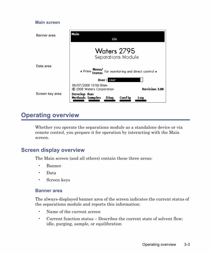
Main screen
Operating overview
Whether you operate the separations module as a standalone device or via remote control, you prepare it for operation by interacting with the Main screen.
Screen display overviewThe Main screen (and all others) contain these three areas:
• Banner• Data• Screen keys
Banner area
The always-displayed banner area of the screen indicates the current status of the separations module and reports this information:
• Name of the current screen• Current function status – Describes the current state of solvent flow;
idle, purging, sample, or equilibration
Banner area
Data area
Screen key area
Operating overview 3-3
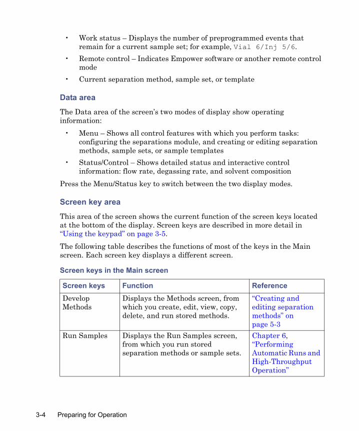
• Work status – Displays the number of preprogrammed events that remain for a current sample set; for example, Vial 6/Inj 5/6.
• Remote control – Indicates Empower software or another remote control mode
• Current separation method, sample set, or template
Data area
The Data area of the screen’s two modes of display show operating information:
• Menu – Shows all control features with which you perform tasks: configuring the separations module, and creating or editing separation methods, sample sets, or sample templates
• Status/Control – Shows detailed status and interactive control information: flow rate, degassing rate, and solvent composition
Press the Menu/Status key to switch between the two display modes.
Screen key area
This area of the screen shows the current function of the screen keys located at the bottom of the display. Screen keys are described in more detail in “Using the keypad” on page 3-5.The following table describes the functions of most of the keys in the Main screen. Each screen key displays a different screen.
Screen keys in the Main screen
Screen keys Function ReferenceDevelop Methods
Displays the Methods screen, from which you create, edit, view, copy, delete, and run stored methods.
“Creating and editing separation methods” on page 5-3
Run Samples Displays the Run Samples screen, from which you run stored separation methods or sample sets.
Chapter 6, “Performing Automatic Runs and High-Throughput Operation”
3-4 Preparing for Operation

Other screen keys
These general screen keys appear frequently in the front-panel menus and screens:
• More – Displays an additional set of screen keys.• Next/Previous – Cycles through a group of related screens at the same
level of the menu hierarchy.• OK – Enters the selected or specified information in a window or dialog
box then proceeds to the next screen.• Cancel – Exits from a dialog box and returns to the previous screen or
used to start over when entering information.• Plate – Opens the Well Selector. You can restrict entry to one well,
depending on where you are in the program when you press the Plate screen key (see “Selecting wells for making injections” on page 4-21).
Other individual screen keys are described in this guide according to their usage.
Using the keypadThe following table describes the functions of the keypad keys on the front panel.
Diag Displays the Diagnostics screen, from which you run instrument diagnostic tests.
Chapter 8, “Diagnostic Testing and Troubleshooting”
Config Displays the Configuration screen, from which you specify values for instrument parameters.
“Setting configuration parameters” on page 3-11
Log Displays the error log. “Using the error log” on page 8-3
Screen keys in the Main screen (Continued)
Screen keys Function Reference
Operating overview 3-5

Note: Parameter fields that are not editable have a dotted-line border. Screen keys that are not available for use are shaded.
Keypad functions
Key Function (for screen navigation)
Function (for plate navigation)1
Moves the cursor one field to the left.
Moves the well cursor one or more positions to the left.
Moves the cursor one field to the right.
Moves the well cursor one or more positions to the right.
Moves the cursor to the field above the current field.
Moves the well cursor one or more positions up.
Moves the cursor to the field below the current field.
Moves the well cursor one or more positions down.
Moves the cursor to the left-most field in the current row. Press twice to move the cursor to the first field in the screen.
Moves the well cursor several positions to the left (depending on plate capacity). Also used to move diagonally.
Moves the cursor to the right-most field in the current row. Press twice to move the cursor to the last field in the screen.
Moves the well cursor several positions to the right (depending on the plate capacity). Also used to move diagonally.
Increases the display contrast.
Decreases the display contrast.
3-6 Preparing for Operation

Displays a context-sensitive Help screen. Press again to display a general Help screen. To close the Help screen, press Exit or Clear. See “Using the Help system” on page 3-9.Closes an open menu or dialog box and returns to the previous screen (not used for Menu/Status).Clears the contents of the current field, or enters INIT, OFF, or other information in selected fields.
Clears selection of one well or a group of wells.
Stores the contents of the current field and advances the cursor to the next field in the screen.
Selects/deselects one well or a group of wells.
Switches the display between the Menu mode and the Status/Control mode.Immediately stops the flow of solvent and suspends the current function (sample processing, priming, refreshing the syringe, and so on). Pressing this key also activates the Run Stopped output switch. Press the Resume screen key to resume or Abort to abort the current function.Enters the corresponding number into the current field, selects the corresponding gradient curve (0 = curve 10), or positions the cursor to the corresponding entry in a list (0 = tenth item).
Keypad functions (Continued)
Key Function (for screen navigation)
Function (for plate navigation)1
?
Exit
Clear
Enter
Menu/Status
StopFlow
0
9
through
Operating overview 3-7
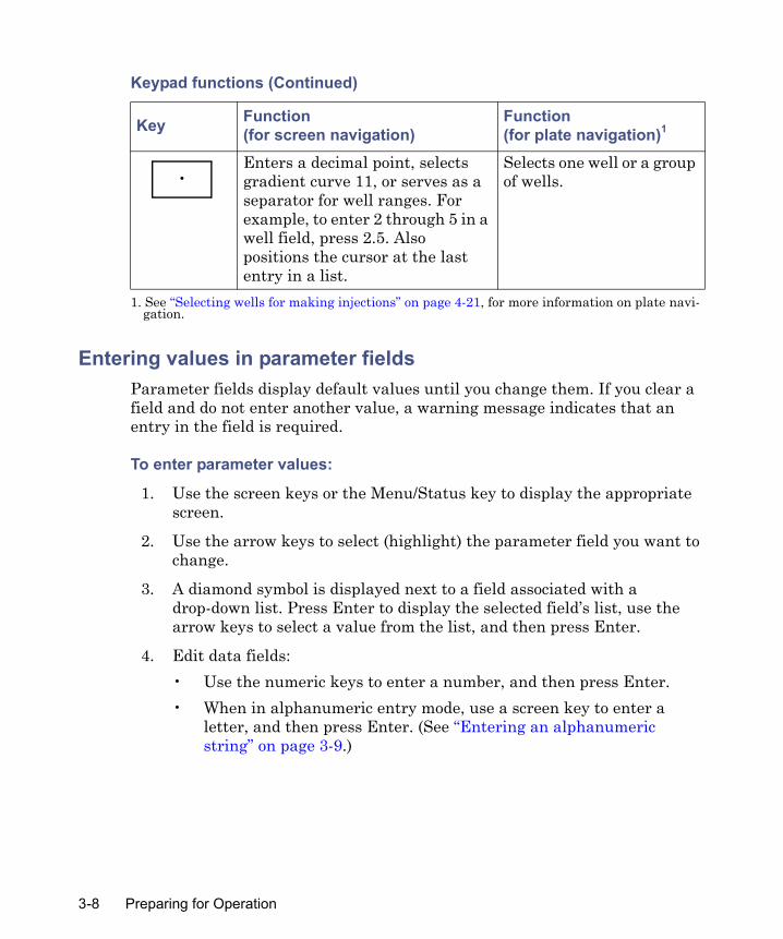
Entering values in parameter fieldsParameter fields display default values until you change them. If you clear a field and do not enter another value, a warning message indicates that an entry in the field is required.
To enter parameter values:
1. Use the screen keys or the Menu/Status key to display the appropriate screen.
2. Use the arrow keys to select (highlight) the parameter field you want to change.
3. A diamond symbol is displayed next to a field associated with a drop-down list. Press Enter to display the selected field’s list, use the arrow keys to select a value from the list, and then press Enter.
4. Edit data fields:• Use the numeric keys to enter a number, and then press Enter.• When in alphanumeric entry mode, use a screen key to enter a
letter, and then press Enter. (See “Entering an alphanumeric string” on page 3-9.)
Enters a decimal point, selects gradient curve 11, or serves as a separator for well ranges. For example, to enter 2 through 5 in a well field, press 2.5. Also positions the cursor at the last entry in a list.
Selects one well or a group of wells.
1. See “Selecting wells for making injections” on page 4-21, for more information on plate navi-gation.
Keypad functions (Continued)
Key Function (for screen navigation)
Function (for plate navigation)1
•
3-8 Preparing for Operation

Selecting/clearing check boxesTo select a check box, use the arrow keys to position the cursor on the check box, and then press any numeric key to place an X in the box and activate the option. To clear a check box deactivating an option, press any numeric key.
Entering an alphanumeric stringWhen you select a field that requires an alphabetic entry, such as a user name or method name, each screen key is automatically labeled with a group of letters. Press the More screen key for additional selections such as uppercase and lowercase letters, backspace, insert, or overstrike. Use the numeric keys and the decimal point character from the keypad to enter numbers or a decimal point. Use the arrow keys to position the text cursor. Press the Clear key to erase the contents of the field.You can enter as many as 30 characters in most alphanumeric fields. To end and save an alphanumeric entry, press Enter.
Example: To enter the name “User2” in the New User Name field
1. Press STUVWX.
2. Press U.
3. Press More and then Lowercase.
4. Press stuvwx.
5. Press s.
6. Press abcdef.
7. Press e.
8. Press mnopqr.
9. Press r.
10. Press 2 on the front panel keypad.
11. Press Enter.
Using the Help systemThe separations module’s Help system describes the parameters associated with user-selectable, editable fields, check boxes, and drop-down lists in
Operating overview 3-9
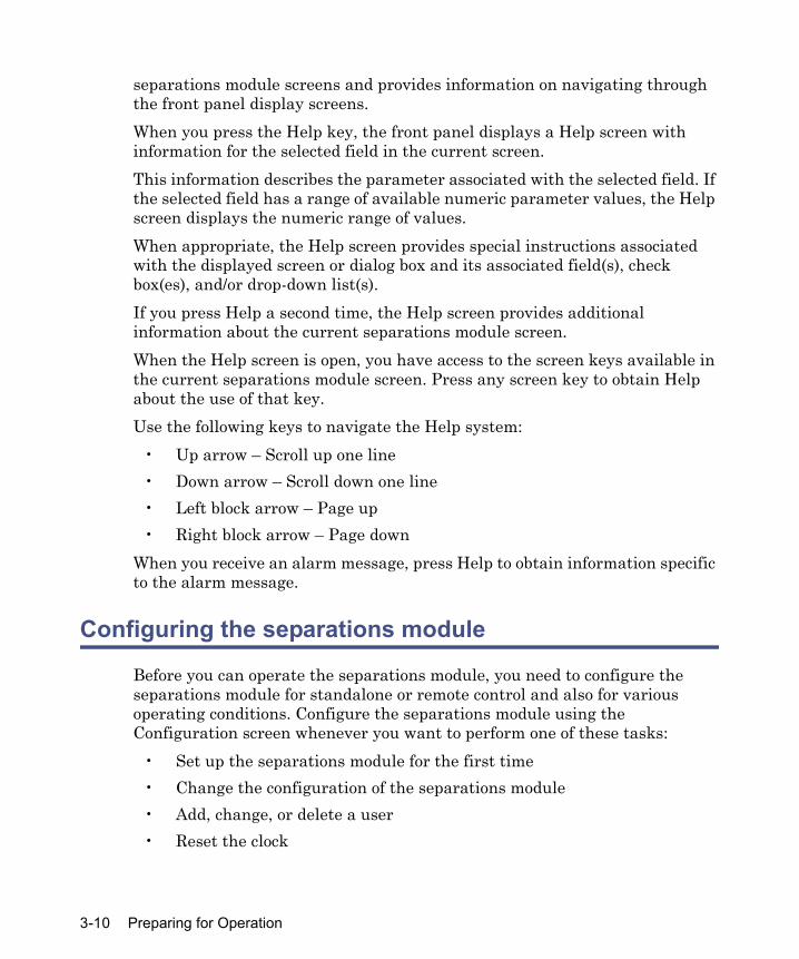
separations module screens and provides information on navigating through the front panel display screens.When you press the Help key, the front panel displays a Help screen with information for the selected field in the current screen.This information describes the parameter associated with the selected field. If the selected field has a range of available numeric parameter values, the Help screen displays the numeric range of values.When appropriate, the Help screen provides special instructions associated with the displayed screen or dialog box and its associated field(s), check box(es), and/or drop-down list(s).If you press Help a second time, the Help screen provides additional information about the current separations module screen.When the Help screen is open, you have access to the screen keys available in the current separations module screen. Press any screen key to obtain Help about the use of that key.Use the following keys to navigate the Help system:
• Up arrow – Scroll up one line• Down arrow – Scroll down one line• Left block arrow – Page up• Right block arrow – Page down
When you receive an alarm message, press Help to obtain information specific to the alarm message.
Configuring the separations module
Before you can operate the separations module, you need to configure the separations module for standalone or remote control and also for various operating conditions. Configure the separations module using the Configuration screen whenever you want to perform one of these tasks:
• Set up the separations module for the first time• Change the configuration of the separations module• Add, change, or delete a user• Reset the clock
3-10 Preparing for Operation

Press the Configure screen key in the Main screen to display the Configuration screen.
Setting configuration parametersSelect the following parameters, as necessary, for your configuration:
• Syringe size, Loop size – Specify the size of the syringe and sample loop. These values are preset at the factory. Change them only when you install a different syringe and/or sample loop.
• System – Selects the operating mode and network address, when required. (See “Configuring the operating mode” on page 3-25.)
• Printer – Selects the type of printer and the baud (data transfer) rate.Tip: The baud rate is automatically set to 1200 when you set the Waters 746 Integrator as the printer type.
• Date format – Selects MDY (for example, Aug 28 08) or DMY (28 Aug 08).
• Pressure units – Selects psi, kilopascal (kPa), or bar units.• Alarm sound – Selects the duration of alarms (continuous or a single
beep).Press the screen keys in the Configuration screen to access other parameters whose values you can specify.
Screen keys in the Configuration screen
Screen key DescriptionUser Names Displays a list of stored user names so that you can
add, change, or remove them. User names are used for documentation purposes only (not for system or password security).
Detectors Scans the IEEE-488 bus and displays a list of the Waters detectors connected to the bus, their addresses, and their firmware revision numbers. The key is active only when the separations module is configured as the system controller and the detectors are powered-on. (See “Configuring the operating mode” on page 3-25.)
Configuring the separations module 3-11

Specifying Signal Conditions for Events In
To define signal conditions that enable Stop Flow and Inject Hold:
1. Press the Events In screen key.
Options Displays a list of the hardware options installed on the separations module.
Set Clock Displays the Set Clock dialog box, allowing you to change the current time and date. (See “Setting configuration parameters” on page 3-11.)
Events In Specifies the external signal conditions to enable the functions stop flow and inject hold. (See the section, below.)
More Toggles between displaying the two sets of screen keys for the Configuration screen.
Reports Specifies the type of information that is included in reports and whether the reports go to a printer or integrator.
Column Switch If a column selection valve is installed, allows you to select custom column position labels of as many as 12 characters each.
Status Layout Used to rearrange the status pages by selecting status features for display. (See “Monitoring system status” on page 4-2.)
Plate Types Displays the Plate Type Configuration dialog box for managing up to 15 plate types. See “Configuring plate types” on page 3-19.
Auto Shutdown Specifies the parameters for automatic shutdown of the separations module. (See “Auto Shutdown” on page 3-17.)
RS-232 Valves Scans the RS-232 port for valves and displays the type and address of any found. (See “Configuring RS-232 valves” on page 3-24.)
Screen keys in the Configuration screen (Continued)
Screen key Description
3-12 Preparing for Operation
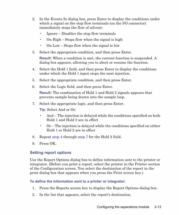
2. In the Events In dialog box, press Enter to display the conditions under which a signal on the stop flow terminals (on the I/O connector) immediately stops the flow of solvent:• Ignore – Disables the stop flow terminals• On High – Stops flow when the signal is high• On Low – Stops flow when the signal is low
3. Select the appropriate condition, and then press Enter. Result: When a condition is met, the current function is suspended. A dialog box appears, allowing you to abort or resume the function.
4. Select the Hold 1 field, and then press Enter to display the conditions under which the Hold 1 input stops the next injection.
5. Select the appropriate condition, and then press Enter.
6. Select the Logic field, and then press Enter.Result: The combination of Hold 1 and Hold 2 signals appears that prevents sample being drawn into the sample loop.
7. Select the appropriate logic, and then press Enter.Tip: Select And or Or:• And – The injection is delayed while the conditions specified on both
Hold 1 and Hold 2 are in effect• Or – The injection is delayed while the conditions specified on either
Hold 1 or Hold 2 are in effect
8. Repeat step 4 through step 7 for the Hold 2 field.
9. Press OK.
Setting report options
Use the Report Options dialog box to define information sent to the printer or integrator. (Before you print a report, select the printer in the Printer section of the Configuration screen. You select the destination of the report in the print dialog box that appears when you press the Print screen key.)
To define the information sent to a printer or integrator:
1. Press the Reports screen key to display the Report Options dialog box.
2. In the list that appears, select the report’s destination.
Configuring the separations module 3-13

Rule: If the RS-232 port is configured for remote control, or you previously set the printer selection to None, you can select only Disable Reporting.
3. Select any option, press any numeric key (to enable the option), and then press Enter: • Gradient table – Generates the gradient table described in the table
on page 5-13.• I/O event table – Generates the I/O table described in the table on
page 5-28.• Detector table – Generates the detector table described in the table
on page 5-32.• Event overview – Generates an overview of all merged tables• Misc. parameters – Generates a list of all parameters not included
in tables• System config – Generates a list of the instrument configuration
parameters• Per-inject data – Generates a list of the minimum, maximum, and
average values for temperature and pressure, the hour and date of each injection, the bar code number, and so on
• Alarms – Generates a list of the error conditions that occurred during each injection
4. Press OK to exit the Report Options dialog box.
5. Press Exit to return to the Main screen.
3-14 Preparing for Operation
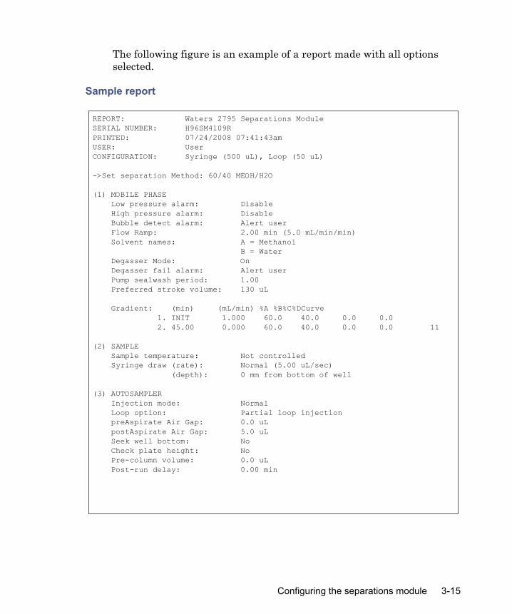
The following figure is an example of a report made with all options selected.
Sample report
REPORT: Waters 2795 Separations ModuleSERIAL NUMBER: H96SM4109RPRINTED: 07/24/2008 07:41:43amUSER: UserCONFIGURATION: Syringe (500 uL), Loop (50 uL)
->Set separation Method: 60/40 MEOH/H2O
(1) MOBILE PHASE Low pressure alarm: Disable High pressure alarm: Disable Bubble detect alarm: Alert user Flow Ramp: 2.00 min (5.0 mL/min/min) Solvent names: A = Methanol B = Water Degasser Mode: On Degasser fail alarm: Alert user Pump sealwash period: 1.00 Preferred stroke volume: 130 uL Gradient: (min) (mL/min) %A %B%C%DCurve 1. INIT 1.000 60.0 40.0 0.0 0.0 2. 45.00 0.000 60.0 40.0 0.0 0.0 11 (2) SAMPLE Sample temperature: Not controlled Syringe draw (rate): Normal (5.00 uL/sec) (depth): 0 mm from bottom of well (3) AUTOSAMPLER Injection mode: Normal Loop option: Partial loop injection preAspirate Air Gap: 0.0 uL postAspirate Air Gap: 5.0 uL Seek well bottom: No Check plate height: No Pre-column volume: 0.0 uL Post-run delay: 0.00 min
Configuring the separations module 3-15

Compression check alarm: Alert userWash Solvent: Methanol/WaterFrequency: Every injectCycles: 1Inject port: 6 secNeedle exterior: 15 secPurge (degassed) solvent: Methanol/WaterEvery inject: 299 uLRapid equilibration: OffColumn re-equilibration: 0.00 min
(4) COLUMNColumn temperature: Not controlledColumn 1: < blank >
(5) I/OChart output: System pressure (6) DETECTORSAbs-1: 486 EnabledAbs-2: Disabled410/2410: Disabled
Table: (min) Detector Action Param 1. INIT 486 (1) Set wavelength 254 2. INIT 486 (1) Set filter 1.0 3. INIT 486 (1) Set AU full scale 2.000 4. INIT 486 (1) Set chart polarity [+] 5. INIT 486 (1) Auto zero OVERVIEW (min) Action 1. INIT Column no change 2. INIT 486(1) 254 nm 3. INIT 486(1) filter 1.0 4. INIT 486(1) 2.000 AUFS 5. INIT 486(1) chart polarity pos 6. INIT 486(1) auto zero 7. INIT 1.000 mL/min 60.0%A 40.0%B 0.0%C 0.0%D c6 8. 45.00 0.000 mL/min 60.0%A 40.0%B 0.0%C 0.0%D c11
->Sample injected at 07/24/2008 01:41:47pm (10.0 uL from 1:A,1) Inject 1 of 1, Line 1 Total points = 383 Minimum Maximum Average System pressure (psi):9531092964 Column temperature (deg C):23.423.423.4 Sample temperature (deg C):24.024.024.0 Degasser vacuum (psia): 3.03.03.0
3-16 Preparing for Operation
Auto ShutdownYou can set up the separations module to shut down automatically after a specified period of inactivity, which is defined as follows:
• No keyboard use• No functions run• No changes sent to the separations module from a remotely-connected
Empower system, Millennium workstation, or MassLynx computer• An error condition that suspends the operation of the separations
moduleAuto Shutdown provides the following two options:
• Idle Shutdown, which allows you to perform these tasks:– Minimize solvent flow when a run ends unattended– Disable temperature controls– Turn off detector lamps
• No Flow Shutdown, which allows you to perform these tasks:– Disable the vacuum degasser– Perform a plunger seal wash– Automatically park plungers after a specified period of zero flow
Tip: For instrument storage lasting one week or more, use methanol, or methanol mixed with HPLC-quality water, to flush the solvent delivery system before shutdown (see “Powering-off the separations module” on page 3-44).
To enable Idle Shutdown:
1. In the Main screen, press Config and then More.
2. Press Auto Shutdn to open the Auto Shutdown dialog box.
Configuring the separations module 3-17

Auto Shutdown dialog box
3. In the Idle Shutdown box, enter a time period of inactivity after which you want the separations module to shut down.Alternative: Press Clear to disable the Auto Shutdown function.
4. In the Idle Method field, select the separation method to be applied when the separations module is shut down. Tip: Only the initial conditions in the method you select are applied during the shutdown period.
5. Press OK. Result: The separations module shuts down when there has been no activity for the specified period.
6. Press Exit.Tip: If you want to use Auto Shutdown to power-off a 2487 or 486 detector lamp, specify a Lamp Off event and a time of INIT in the I/O Events Timed Table screen (see “Setting I/O parameter values” on page 5-27).
3-18 Preparing for Operation

To enable No Flow Shutdown:
1. In the Main screen, press Config and then More.
2. Press Auto Shutdn to open the Auto Shutdown dialog box.
3. In the Solvent Manager box, enter the time period that the system must remain at no-flow before the plunger seals are automatically washed.
4. In the Degasser box, enter a time period that the system must remain at no-flow before the degasser is automatically turned off.
5. Press OK.
Configuring plate types
You can configure a maximum of 15 possible plate types for use with the separations module, some of which are preconfigured and not editable.Tip: When you select a preconfigured plate type, the parameter fields indicate the measured dimensions for the specific plate, which are not editable (indicated by a dotted line surrounding the field).
To customize a preconfigured plate type for the separations module:
1. In the Configuration screen, press Plate Types.
2. In the Plate Type Configuration dialog box, select the plate type from the Name drop-down list. Result: The remaining (non-editable) boxes fill with values corresponding to the selected plate type. To configure a custom plate, see the section, below.
Caution: If you use buffered solvents, enter a no-flow time for the solvent manager to prevent precipitates from forming on the plungers, which can in turn damage the high pressure seals. Set this time period shorter than the estimated time it takes for the precipitates to form. The default is 5 minutes.
Caution: To avoid damaging the separations module, Waters recommends that you consult the table on page C-6 before configuring plates. Be sure to read all the recommendations in the table footnotes.
Configuring the separations module 3-19

3. In the Sequential reference box, select the processing order (see the table, below).
The following table describes the fields in the Plate Type Configuration dialog box. See the table on page C-6 for recommended plate types (and their dimensions) for use with the separations module.
Caution: Use of incorrect dimensions can cause needle damage.
Plate type configuration parameters
Parameter field DescriptionName Name of the plate type. Use as many as 30
characters to identify a plate type. Some of the 15 plate types are preconfigured. To move from one plate type to the adjacent plate type in the drop-down list, press the Previous or Next screen key. The default plate type appears with an asterisk in the Name field and the words “Default Plate Type” are displayed below the Name field.
Wells Number of wells on the plate selected in the Name field. The parameters for each plate type are:
Sequential reference Direction and sequence of well injections for the selected plate. See the table on page 3-40.
Well A1 offset (mm)Left
Rear
The distance from the center of well A:1 to the left outer edge of the plate.
The distance from the center of well A:1 to the rear outer edge of the plate. The minimum rear offset value is 8.3 mm. See the figure on page 3-22.
Number of Wells Number of Rows Number of Columns24
48
96
384
4
6
8
16
6
8
12
24
3-20 Preparing for Operation

Configuring custom platesTip: You can use one of the preconfigured plate types to create a custom plate. Before following the procedure below, select the preconfigured plate type that most resembles the custom plate you want to create.
Required material
Ruler or straight-edge scaled in millimeters
To configure a custom plate:
1. In the Plate Type Configuration dialog box, press Copy.
2. In the Custom Plate name box, enter a custom plate name (see “Using the keypad” on page 3-5), and then press Enter. Result: The Plate Type Configuration parameter boxes become editable (surrounded by a solid line).
3. Using a ruler or straight-edge scaled in millimeters, measure the dimensions for the custom plate as shown in the figures on page 3-22 and page 3-23, and then enter each value in the appropriate parameter box in the Plate Type Configuration screen.
Spacing (mm)Row-to-row
Column-to-column
The distance from the centerline of the wells in one row to the centerline of the wells in an adjacent row.
The distance from the centerline of the wells in one column to the centerline of the wells in an adjacent column. See the figure on page 3-22.
Vertical (mm)1
Plate heightWell depth
Total plate heightThe well depth (distance from the top of the plate to the bottom of the well)
1. See table on page C-6 for dimensions of the plates recommended for use with the e2795 Sepa-rations Module.
Plate type configuration parameters (Continued)
Parameter field Description
Configuring the separations module 3-21
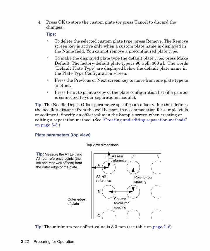
4. Press OK to store the custom plate (or press Cancel to discard the changes).Tips: • To delete the selected custom plate type, press Remove. The Remove
screen key is active only when a custom plate name is displayed in the Name field. You cannot remove a preconfigured plate type.
• To make the displayed plate type the default plate type, press Make Default. The factory-default plate type is 96 well, 300 μL. The words “Default Plate Type” are displayed below the default plate name in the Plate Type Configuration screen.
• Press the Previous or Next screen key to move from one plate type to another.
• Press Print to print a copy of the plate configuration list (if a printer is connected to your separations module).
Tip: The Needle Depth Offset parameter specifies an offset value that defines the needle’s distance from the well bottom, in accommodation for sample vials or sediment. Specify an offset value in the Sample screen when creating or editing a separation method. (See “Creating and editing separation methods” on page 5-3.)
Plate parameters (top view)
Tip: The minimum rear offset value is 8.3 mm (see table on page C-6).
A
B
C
1 2 3Tip: Measure the A1 Left and A1 rear reference points (the left and rear well offsets) from the outer edge of the plate.
Outer edge of plate
Top view dimensions
Row-to-row spacing
A1 left reference
A1 rear reference
Column- to-column spacing
3-22 Preparing for Operation

Plate parameters (side view)
The following table describes the preconfigured plate types for the separations module. The plate type names appear as displayed in the Name parameter of the Plate Type Configuration dialog box.
Preconfigured plate types
Plate type name Plate type description Part number24 uCfuge tube, 1.5 mL
24-well, 1.5- mL microcentrifuge tube holder
405000560
24 vial (open access),2 mL
24-well, 2-mL vial, open access plate 200000114
48 vial holder, 2 mL 48-well, 2-mL vial holder 40500056248 uCfuge tube, 0.5 mL
48-well, 0.5- mL microcentrifuge tube holder
405000561
96 well w/700 uL insert
96-well with 700-μL glass insert plate
186000349
96 well (tall), 350 uL 96-well tall, 350-μL polypropylene WAT058943
* The Needle Depth Offset parameter is part of the separation method. See “Creating and editing separation methods” on page 5-3.
Side view dimensions
A
Needle downNeedle up
Plate height Needle depth offset*
Well depth
Configuring the separations module 3-23

Configuring RS-232 valvesThe separations module allows you to configure up to three external RS-232 valves. The system will scan for the valve type and address.Tip: If you attach the RS-232 valves before powering on the separations module, you do not need to configure the valves.
To attach RS-232 valves:
1. Attach the RS-232 adapter to the RS-232 port on the rear of the separations module. You can use the adapter to attach up to three RS-232 valves to your system.
2. Using the address dial on the back of each RS-232 valve, set the address of each valve.Tip: Each valve address must be unique. Numbering must start at Address 1 and should be sequential.
To configure RS-232-valves:
1. In the Main screen, press Config and then More twice.
2. Press RS-232 Valves to open the RS-232 Valves dialog box.
3. Press Scan. The system scans for valves and displays the results.
4. You can then control the valves from the Status screen, and through the separation method’s timed event table (see “Setting I/O parameter values” on page 5-27).
96 well (tall), 1 mL 96-well tall, 1-mL polypropylene WAT05895796 well (tall), 2 mL 96-well tall, 2-mL, polypropylene WAT05895896-well, 300 uL (Default)
96-well, 300-μL polypropylene or polystyrene
Non-Waters1
384-well, 80 uL 384-well, 80-μL polystyrene Non-Waters1
1. Confirm the dimensions of all non-Waters plates. For more information on these and other e2795-compatible plates, see page C-6.
Preconfigured plate types (Continued)
Plate type name Plate type description Part number
3-24 Preparing for Operation
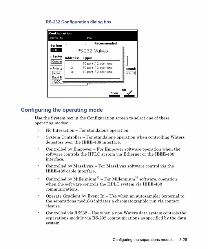
RS-232 Configuration dialog box
Configuring the operating modeUse the System box in the Configuration screen to select one of these operating modes:
• No Interaction – For standalone operation.• System Controller – For standalone operation when controlling Waters
detectors over the IEEE-488 interface.• Controlled by Empower – For Empower software operation when the
software controls the HPLC system via Ethernet or the IEEE-488 interface.
• Controlled by MassLynx – For MassLynx software control via the IEEE-488 cable interface.
• Controlled by Millennium32 – For Millennium32 software, operation when the software controls the HPLC system via IEEE-488 communications.
• Operate Gradient by Event In – Use when an autosampler (external to the separations module) initiates a chromatographic run via contact closure.
• Controlled via RS232 – Use when a non-Waters data system controls the separations module via RS-232 communications as specified by the data system.
Configuring the separations module 3-25
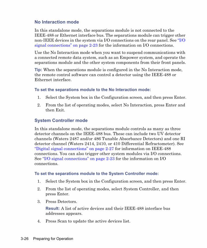
No Interaction mode
In this standalone mode, the separations module is not connected to the IEEE-488 or Ethernet interface bus. The separations module can trigger other non-IEEE devices in the system via I/O connections on the rear panel. See “I/O signal connections” on page 2-23 for the information on I/O connections. Use the No Interaction mode when you want to suspend communications with a connected remote data system, such as an Empower system, and operate the separations module and the other system components from their front panels.Tip: When the separations module is configured in the No Interaction mode, the remote control software can control a detector using the IEEE-488 or Ethernet interface.
To set the separations module to the No Interaction mode:
1. Select the System box in the Configuration screen, and then press Enter.
2. From the list of operating modes, select No Interaction, press Enter and then Exit.
System Controller mode
In this standalone mode, the separations module controls as many as three detector channels on the IEEE-488 bus. These can include two UV detector channels (Waters 2487 and/or 486 Tunable Absorbance Detectors) and one RI detector channel (Waters 2414, 2410, or 410 Differential Refractometer). See “Digital signal connections” on page 2-27 for information on IEEE-488 connections. You can also trigger other system modules via I/O connections. See “I/O signal connections” on page 2-23 for the information on I/O connections.
To set the separations module to the System Controller mode:
1. Select the System box in the Configuration screen, and then press Enter.
2. From the list of operating modes, select System Controller, and then press Enter.
3. Press Detectors. Result: A list of active devices and their IEEE-488 interface bus addresses appears.
4. Press Scan to update the active devices list.
3-26 Preparing for Operation

5. Press OK and then Exit.Result: The separations module is ready to control Waters detectors using separation methods and sample sets.
Controlled by Empower mode
In this remote control mode, Empower software controls the HPLC system via the Ethernet interface or the IEEE-488 interface bus (but not both simultaneously). Connect the Ethernet or IEEE-488 cable as described in “Digital signal connections” on page 2-27.
To set the separations module to the Controlled by Empower mode:
1. Select the System box in the Configuration screen, and then press Enter to display the list of operating modes.
2. From the list of operating modes, select Controlled by Empower, and then press Enter. Result: The network address box is highlighted.
3. Press Enter to display the network address drop-down list.
4. Depending on which interface you are using, make one of these selections:• For Ethernet, select the Auto/Ethernet setting.• For IEEE-488, select an IEEE-488 address that is unused by other
chromatographic components connected to the Empower system.
5. Press Enter and then Exit. Result: The separations module is ready to be controlled from the Empower system.
See “Controlled by Empower or Millennium software” on page 6-2 for information about performing runs under Empower or Millennium software control.
Controlled by MassLynx mode
In this remote control mode, MassLynx software controls the separations module. MassLynx software uses the IEEE-488 interface between the MassLynx computer and the separations module.
Configuring the separations module 3-27
To set the separations module to the Controlled by MassLynx mode:
1. Select the System box in the Configuration screen, and then press Enter to display a list of operating modes.
2. From the list of operating modes, select Controlled by MassLynx, and then press Enter. Result: The Network Address box is highlighted.
3. Press Enter to display a list of addresses.
4. Select an address that is unused by other chromatographic components connected to the MassLynx computer, and then press Enter and then Exit.
See “Controlled by MassLynx software” on page 6-3 for details on performing runs under MassLynx software control.
Controlled by Millennium32 mode
In this remote control mode, a Millennium workstation running Millennium32 software controls the operation of your HPLC system using the IEEE-488 interface bus. Connect the IEEE-488 cable as described in “Digital signal connections” on page 2-27.
To set the separations module to the Controlled by Millennium32 mode:
1. Select the System box in the Configuration screen, and then press Enter to display a list of operating modes.
2. From the list of operating modes, select Controlled by Millennium32, and then press Enter. Result: The Network Address box is highlighted.
3. Press Enter to display a list of addresses.
4. Select an address that is unused by other chromatographic components connected to the Millennium workstation, and then press Enter and then Exit.
See “Controlled by Empower or Millennium software” on page 6-2 for details on performing runs under Millennium software control.
3-28 Preparing for Operation

Controlled by Operate Gradient by Event In mode
In this mode, an external autosampler (a Waters 2700 Sample Manager, for example) initiates the start of a chromatographic run and performs the inject function (instead of the separations module). The separations module has no control of IEEE-488 devices, but can control non-IEEE devices using the I/O connections on its rear panel. See “I/O signal connections” on page 2-23 for the information on I/O connections.
To set the separations module to the Operate Gradient by Event In mode:
1. Select the System box in the Configuration screen, and then press Enter to display a list of operating modes.
2. From the list of operating modes, select Operate Gradient by Event In, and then press Enter.
3. Press Events In to display the Events In dialog box. Tip: For information on defining Events In conditions, see “Specifying Signal Conditions for Events In” on page 3-12.
4. Set the Stop Flow box to the appropriate condition (Ignore, High, or Low), and then press Enter.• Choose Ignore if the Stop Flow I/O terminals of the separations
module are not used.• Choose High if the output connection from the external autosampler
to the Stop Flow I/O terminals of the Separations Module changes to a high (more positive) TTL-level.
• Choose Low if the output connection from the external autosampler to the Stop Flow I/O terminals of the separations module changes to a low (more negative) TTL-level.
5. Set the Hold 1 box to the appropriate condition (High or Low), and then press Enter.• Choose High if the output connection from the external autosampler
to the Hold 1 Inject terminals of the separations module changes to a high (more positive) TTL-level to initiate a chromatographic run (and prevent an injection by the separations module).
• Choose Low if the output connection from the external autosampler to the Hold 1 Inject terminals of the separations module changes to a low (more negative) TTL-level to initiate a chromatographic run (and prevent an injection by the separations module).
Configuring the separations module 3-29

Requirement: If you are configuring the separations module with a Waters 2700 Sample Manager, select Low.
6. Set the Logic box to Or, and then press Enter.
7. Set the Hold 2 box to Ignore, and then press Enter.
8. Press OK to save your selections.
Controlled via RS-232 mode
In this remote control mode, a non-Waters data system (a mass spectrometry system, for example) controls the separations module using RS-232 communications. The separations module disconnects from the Ethernet or IEEE-488 interface bus when this mode is selected. The separations module can control other non-IEEE devices in the HPLC system using the I/O connections on the rear panel. See “I/O signal connections” on page 2-23 for the information on I/O connections.
To set the separations module to the Controlled via RS-232 mode:
1. Select the System box in the Configuration screen, and then press Enter to display a list of operating modes.
2. Select Controlled via RS232, and then press Enter and then Exit. Tip: If you experience repeated problems when using a third-party data system, reconfigure the separations module to No Interaction mode. If the problem persists, refer to the appropriate section of this guide. If the problem occurs when using a third-party data system, but not when the instrument is configured in No Interaction mode, contact the data system’s vendor.
Preparing the solvent management system
The separations module is designed to provide a pulse-free, accurate, and precise flow of solvent. For optimal performance, perform these tasks:
• Properly prepare the solvent reservoirs• Use degassed solvents• Prime the solvent management system• Prime the plunger-seal-wash pump
3-30 Preparing for Operation
Tip: To maintain the efficiency of the solvent management system, and to obtain accurate, reproducible chromatograms, use only HPLC-grade solvents.
Preparing solvent reservoirsRequirements:
• Choose solvent reservoirs that provide a snug fit for the reservoir caps supplied in the startup kit. (Waters recommends 1-L reservoirs.)
• To maintain adequate solvent head pressure and ensure proper solvent delivery, position the solvent reservoirs above the level of the solvent management system, at least 51 cm (20 inches) above the laboratory bench.
• To prevent solvent overflow, avoid pressurized solvent reservoir bottles. Pressures above 5 psi can force solvent through the internal components of the gradient proportioning valve (GPV), possibly causing spillover into the solvent waste reservoir or an adverse mixture with other solvents in the GPV.
General recommendations:• When using the instrument for general chromatography (i.e. reverse
and/or normal phase and gel permeation [GPC]), use high-quality lab glassware made of borosilicate glass for all reservoirs (solvent, seal wash & needle wash).
• When using techniques such as ion chromatography where glass containers can contribute ionic contamination (sodium and/or chloride ions), it is acceptable to use laboratory-grade polypropylene or polyethylene containers as reservoirs.
• When using the instrument in combination with a mass spectrometric detector, refer to recommendations within the most recent version of “Controlling Contamination in UPLC/MS and HPLC/MS Systems” on the Waters’ website (www.waters.com) in the Support Library, under Waters Division/Services & Support.
Install the solvent and vent lines as described in “Connecting tubing and attachments” on page 2-8.
Warning: Observe safe laboratory practices when you handle solvents. Refer to the Material Safety Data Sheets for the solvents you use.
Preparing the solvent management system 3-31

Degassing solventsIn-line vacuum degassing reduces the total dissolved gas in the mobile phase. For more information on vacuum degassing, see “Degasser considerations” on page 1-8.Tip: For proper operation of the in-line vacuum degasser, you must fill each vacuum chamber with solvent. Use the dry prime direct function to prime all solvent lines.
To control the in-line vacuum degasser from the Status screen:
1. Press Menu/Status.
2. On the status screen, press Next Page (if necessary) to display the degasser boxes.
3. Select the Degasser mode box, and then press Enter.
4. From the list of degasser modes, select one of these modes:• On – The degasser operates continuously• Off – The degasser does not operateTip: Do not operate the degasser in the continuous (On) mode unless solvent is flowing through the supply tubes. Without solvent flow, excess solvent vapor can condense on the walls of the degasser’s vacuum chamber, mimicking a vacuum chamber leak.
5. Select the desired operating mode, and then press Enter. Result: The Pressure box displays the current vacuum level in psia, bar, or kPa.
Setting the wash sequenceA wash sequence option is part of the separation method. By default, the wash sequence is set to Wash-Purge. The alternative is the Purge-Wash-Purge sequence in which an additional purge of the syringe is performed before the Needle-Wash. This option, which uses additional degasser purge solvent, can prove useful in applications where the samples are in serum or salt-containing matrices.
3-32 Preparing for Operation
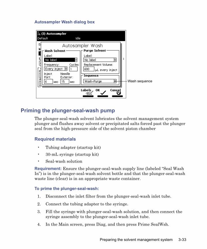
Autosampler Wash dialog box
Priming the plunger-seal-wash pumpThe plunger-seal-wash solvent lubricates the solvent management system plunger and flushes away solvent or precipitated salts forced past the plunger seal from the high-pressure side of the solvent piston chamber
Required materials
• Tubing adapter (startup kit)• 30-mL syringe (startup kit)• Seal-wash solution
Requirement: Ensure the plunger-seal-wash supply line (labeled “Seal Wash In”) is in the plunger-seal-wash solvent bottle and that the plunger-seal-wash waste line (clear) is in an appropriate waste container.
To prime the plunger-seal-wash:
1. Disconnect the inlet filter from the plunger-seal-wash inlet tube.
2. Connect the tubing adapter to the syringe.
3. Fill the syringe with plunger-seal-wash solution, and then connect the syringe assembly to the plunger-seal-wash inlet tube.
4. In the Main screen, press Diag, and then press Prime SealWsh.
Wash sequence
Preparing the solvent management system 3-33

5. Press Start to begin the seal-wash priming procedure, and then push on the syringe plunger to push plunger-seal-wash solvent through the system.
6. When the plunger-seal-wash solvent flows out the plunger-seal-wash waste tube, press Halt.Tip: If you do not press Halt, the seal-wash pump priming procedure stops after 15 minutes.
7. Press Close to return to the Diagnostics screen, and then press Exit to return to the Main screen.Tip: You can use the same solvent for both the purge solvent and the plunger-seal-wash solvent, depending on your application.
8. Remove the syringe and adapter, reconnect the filter, and place the plunger-seal-wash inlet tube into the purge/plunger-seal-wash solvent reservoir.
Priming the solvent management systemPrime the solvent management system using one of these priming methods:
• Dry Prime when the solvent lines are dry • Wet Prime when you want to switch from one solvent to another (see
“Wet priming the system” on page 4-15)Once you prepare the solvent management system for operation, you must prepare the sample management system.
Preparing the sample management system for operation
Prepare the sample management system for operation after you prepare the solvent management system. Preparing the sample management system involves these tasks:
• Priming the needle-wash pump• Refreshing the syringe• Loading the sample plates
Before using the sample management system for the first time, become familiar with the procedures in “Monitoring system status” on page 4-2, and in “Performing direct functions” on page 4-9.
3-34 Preparing for Operation

Priming the needle-wash pumpThe needle-wash pump flushes the needle in the sample management system with wash solvent, preventing carryover of sample between injections. The needle wash also extends the life of the inject port seat by removing buffered mobile phase and sample from the needle.Prime the needle-wash pump when it lacks flow or you are changing the wash solvent.
Selecting the needle-wash and purge solventsUse a needle-wash solvent based on the sample and mobile phase chemistries, making sure all solutions/buffers are miscible and soluble. The following table lists some needle-wash and purge solvents recommended for use with certain mobile phase conditions. High sample concentrations can require other needle wash solvents.
Required materials
• 30-mL syringe (startup kit)• Tubing adapter (startup kit)• Wash solvent
Tip: Be sure the needle-wash tubing and reservoirs are installed properly (see “Installing the wash reservoirs” on page 2-14).
Suggested needle wash and purge solvents
Chromatographic condition Wash solvent Purge solvent
Buffered aqueous, reversed-phase
50 to 100% MeOH or ACN
90% H2O, 10% MeOHor 50% H2O, 50% MeOHor 100% H2O, 0 to 50% MeOH or ACN
Non-aqueous, reversed-phase
100% MeOH Mobile phase
Normal phase Mobile phase Mobile phaseGPC Mobile phase Mobile phaseIon exchange 90% H2O, 10% MeOH H2O (ion exchange mobile
phase is highly buffered)
Preparing the sample management system for operation 3-35

To prime the needle-wash pump:
1. Remove the inlet filter from the needle-wash inlet tube.
2. Connect the syringe adapter to the 30-mL syringe.
3. Fill the syringe with wash solvent, and connect it to the wash-solvent inlet tube.
4. In the Main screen, press Diag.
5. In the Diagnostics screen, press Prime NdlWash.
6. Press Start to begin the needle wash, and then push lightly on the syringe plunger to force needle-wash solvent through the needle-wash system. If solvent does not flow out the needle-wash-waste tubing within 30 seconds, press Start a second time. Tip: If solvent still does not flow out the waste line, check for leaks in the tubing or sample management compartment.
7. When needle-wash solvent flows out of the needle-wash waste tube, press Halt.Tip: If you do not press Halt, the needle-wash prime procedure stops after 30 seconds.
8. Press Close and then Exit to return to the Main screen.
9. Remove the syringe and adapter, reconnect the filter, and place the solvent line back in the needle-wash solvent reservoir.
Refreshing the syringeRefresh the syringe under these conditions:
• The solvent management system is primed• Solvents are changed• Bubbles appear in the syringe• The beginning of each day
3-36 Preparing for Operation

Recommendations:• To prevent degradation to the syringe and valves, avoid using salt
buffers in the purge solvent. Use a low concentration (0% to 50%) organic-aqueous solvent that is similar to the mobile phase, initial gradient conditions, or sample diluent (see the table on page 3-35).
• When you refresh (purge) the syringe for the first time or change the purge solvent, set the number of syringe strokes to 10 and the replacement volume to 600 µL. This volume fills the entire degasser chamber and the associated inlet tubing (with the standard 500-µL syringe installed).
To refresh the syringe:
1. In the Status screen, activate the degasser by selecting the On mode in the Degasser box (see “Monitoring system status” on page 4-2).
2. In the Status screen, press Direct Functions.
3. On the Direct Functions menu, select Refresh Syringe, and then press Enter.
4. In the Refresh Syringe dialog box, enter the number of syringe strokes and the replacement volume of degassed solvent in the appropriate boxes. Tip: Start with 3 syringe strokes and 600 µL replacement volume. To prime a new or dry instrument, or when you change the purge solvent, refer to the recommendation for first time use, above.
5. Press OK.
Preparing the sample management system for operation 3-37

Loading the sample plates
The separations module’s plate carrier holds as many as four rectangular plates that you load through the front panel compartment door. Load each plate so that position A:1 (or 1) is located in the left-hand, rear corner. The front edge of the plate must be behind the guide button on the carrier’s front edge.The plate carrier guides hold each plate loosely in place until the plate is moved to the Inject position. At that time, a plate-positioning spring pushes the plate towards the A:1 corner and holds it in position.To move the plate carrier from one position to the next, press Next, or press the color-coded plate number key in the Door Is Open dialog box.Tip: The separations module cannot draw or load samples when the sample compartment door is open.
Caution: • To avoid damage to the needle or XYZ mechanism, do not use vial
caps less than 8.8 mm in diameter (OD).• Use of polyethylene cap mats below 15 °C can cause damage to the
needle or XYZ mechanism. If the sample manager is maintained above 15 °C, a polyethylene cap mat for 96 square well plates is acceptable (see “e2795 separations module spare parts” on page C-4). However, at temperatures below 15 °C, the mat can become rigid and cause lifting of the plate from the carrier in the injection cycle. Sample stability can also decrease. If the sample manager is maintained from 4 to 15 °C, a PTFE/silicone cap mat is recommended (see “e2795 separations module spare parts” on page C-4).
• Some adhesive sealing materials can clog the inject port and needle. Use thin aluminum foil to seal 96- and 384-well plates. Some heat-sealable foils are also acceptable (see “e2795 separations module spare parts” on page C-4).
3-38 Preparing for Operation

Positioning the sample plate
Tip: If you power-on the separations module with the sample compartment door open, close the door, and then reopen it to replace a sample plate on the carrier.
To load the plates onto the plate carrier:
1. Open the separations module’s sample compartment door.
2. In the Door is Open dialog box, press Next.Alternative: Select the desired plate number to position the plate carrier for loading the appropriate plate.Carrier plate positions are numbered 1 through 4, with individual color identification as follows:• Position 1 = Blue• Position 2 = Yellow• Position 3 = Red• Position 4 = Green
Plate carrier
Sample compartment door (open)
Guidebutton
Preparing the sample management system for operation 3-39
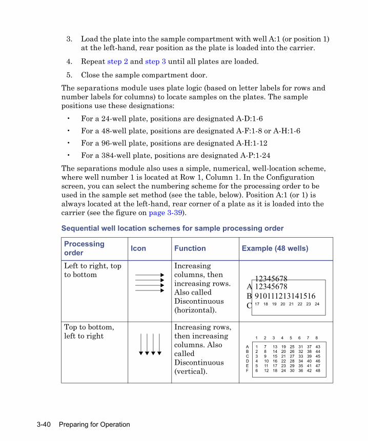
3. Load the plate into the sample compartment with well A:1 (or position 1) at the left-hand, rear position as the plate is loaded into the carrier.
4. Repeat step 2 and step 3 until all plates are loaded.
5. Close the sample compartment door. The separations module uses plate logic (based on letter labels for rows and number labels for columns) to locate samples on the plates. The sample positions use these designations:
• For a 24-well plate, positions are designated A-D:1-6• For a 48-well plate, positions are designated A-F:1-8 or A-H:1-6• For a 96-well plate, positions are designated A-H:1-12• For a 384-well plate, positions are designated A-P:1-24
The separations module also uses a simple, numerical, well-location scheme, where well number 1 is located at Row 1, Column 1. In the Configuration screen, you can select the numbering scheme for the processing order to be used in the sample set method (see the table, below). Position A:1 (or 1) is always located at the left-hand, rear corner of a plate as it is loaded into the carrier (see the figure on page 3-39).
Sequential well location schemes for sample processing order
Processing order Icon Function Example (48 wells)
Left to right, top to bottom
Increasing columns, then increasing rows. Also called Discontinuous (horizontal).
Top to bottom, left to right
Increasing rows, then increasing columns. Also called Discontinuous (vertical).
1234567891011121314151617 18 19 20 21 22 23 24
12345678ABC
1 7 13 19 25 31 37 432 8 14 20 26 32 38 443 9 15 21 27 33 39 454 10 16 22 28 34 40 465 11 17 23 29 35 41 476 12 18 24 30 36 42 48
ABCDEF
1 2 3 4 5 6 7 8
3-40 Preparing for Operation

For more information on configuring sample plates, see “Configuring plate types” on page 3-19. For more information on selecting individual well locations or grouping wells, see “Selecting wells for making injections” on page 4-21.
Adding new sample vials during a runIf you need to add new sample vials while the separations module is processing a sample set, use these guidelines to minimize interruptions during the run:
• Keep the new sample vial(s) at hand so that you minimize the amount of time that the sample compartment door is open.
• Wait until the run time displayed on the front panel exceeds 30 seconds before adding the sample(s)
• Do not add any sample(s) during the run’s final 30 seconds.• Ensure that the sample compartment door is closed at the start of each
injection, when injection commands (selecting vial, washing the needle, drawing sample, and so forth) are executing.
Horizontal serpentine
Left to right until end of row, then right to left starting at next row. Also called Continuous (horizontal).
Vertical serpentine
Top to bottom until end of column, then bottom to top starting at the next column. Also called Continuous (vertical).
Sequential well location schemes for sample processing order (Continued)
Processing order Icon Function Example (48 wells)
1 2 3 4 5 6 7 816 15 14 13 12 11 10 917 18 19 20 21 22 23 2432 31 30 29 28 27 26 2533 34 35 36 37 38 39 4048 47 46 45 44 43 42 41
1 2 3 4 5 6 7 8
ABCDEF
1 12 13 24 25 36 37 482 11 14 23 26 35 38 473 10 15 22 27 34 39 464 9 16 21 28 33 40 455 8 17 20 29 32 41 446 7 18 19 30 31 42 43
ABCDEF
1 2 3 4 5 6 7 8
Preparing the sample management system for operation 3-41

Preparing the separations module for operation
This section explains how to prepare the separations module for operation. The instructions provide the sequence of steps to prime, equilibrate, and purge a separations module that is in one of the following states:
• A new or dry separations module• A separations module that is powered-off or left idle for a significant
time with no flow• A recently idled separations module (to quickly refresh the system in
between runs)• A separations module that requires a solvent change (from a buffered
solvent to an organic solvent)For step-by-step instructions on how to use direct functions to prime, equilibrate, and purge the separations module, and to fully ready the separations module for running samples, see “Monitoring system status” on page 4-2.
Preparing a new or dry separations module for operation
To change from a buffered solvent to a totally organic solvent:
1. Prime the plunger-seal wash pump (see “Priming the plunger-seal-wash pump” on page 3-33).
2. Prime the needle wash pump (see “Priming the needle-wash pump” on page 3-35).
3. Fill all four solvent reservoirs with fresh solvent filtered and degassed by vacuum filtration (see “Preparing solvent reservoirs” on page 3-31).Tip: To maximize degasser efficiency (and fill all four degasser chambers with solvent), fill all four solvent reservoirs (even if you use fewer than four solvents). If you choose water as one of the “unused” solvents, change the water weekly to prevent bacterial contamination.
4. Set the degasser to On (see “Degassing solvents” on page 3-32).
5. Perform a dry prime to fill each solvent line and degasser chamber (see “Dry priming the system” on page 4-12).
3-42 Preparing for Operation

6. Equilibrate the solvent in the degasser chamber by setting a flow rate of 0.000 mL/min for 5 min (see “Equilibrating solvents in the in-line vacuum degasser” on page 4-16).
7. Run System Prep (see “Running System Prep” on page 4-14).
Preparing an idle or powered-off separations module for operation
To prime, equilibrate, and purge the separations module that is powered-off or idle with no solvent flow:
1. Check plunger-seal-wash fluid levels, refilling and priming the reservoirs, if necessary (see “Priming the plunger-seal-wash pump” on page 3-33).
2. Check needle wash fluid levels, refilling and priming the reservoir, if necessary (see “Priming the needle-wash pump” on page 3-35).
3. Set the degasser to On (see “Degassing solvents” on page 3-32).
4. Run System Prep (see “Running System Prep” on page 4-14).
Changing from a buffered solvent to an organic solvent
To change from a buffered solvent to a totally organic solvent in the separations module
1. Remove the solvent line from the reservoir containing the buffered solvent.
2. Specifying a flow rate of 2.000 mL/min, perform a wet prime until air begins to enter the line (see “Wet priming the system” on page 4-15).
Caution: If you just performed the steps from the procedure, below, for changing from a buffered solvent to an organic solvent, ensure that the plunger-seal wash and needle-wash solvents are compatible with the new solvents.
Caution: To avoid salts precipitating in the separations module, use an intermediate solvent such as water when you change from buffers to high-organic-content solvents (see “Solvent miscibility” on page D-5).
Preparing the separations module for operation 3-43
3. Place the previously removed solvent line into filtered HPLC-grade water, and perform a wet prime for 10 min at 5 mL/min (see “Wet priming the system” on page 4-15).
4. Remove the solvent line from the HPLC-grade water.
5. Fill a clean solvent reservoir with the organic solvent, and place the solvent line in the reservoir.
6. Perform the procedure, above, for preparing an idle or powered-off separations module for operation.
Powering-off the separations module
Before you power-off the separations module, remove any buffered mobile phase present in the flow path (see “Flushing the flow path, below).
Flushing the flow path
To flush buffered mobile phase from the flow path:
1. Replace the buffered mobile phase with HPLC-quality water, and wet prime the system for 10 minutes at 3 mL/min (see “Wet priming the system” on page 4-15).
2. Refresh the syringe (see “Refreshing the syringe” on page 3-36).
3. Replace the plunger-seal-wash solvent with a fresh solution of 80% water/20% methanol or a miscible solvent, and prime the plunger-seal-wash pump (see “Priming the plunger-seal-wash pump” on page 3-33).
4. Replace the water mobile phase with a solution of 90% methanol/10% water, and flush the system for 10 minutes at 3 mL/min.
5. Replace the needle-wash solvent with a solution of 90% methanol/10% water or a miscible solvent, and perform a needle-wash prime (see “Priming the needle-wash pump” on page 3-35).
Caution: To avoid damaging the column, remove it before you perform the following procedure.
3-44 Preparing for Operation
Powering-off
To power-off the separations module:
1. Ensure that the system is flushed properly (see “Flushing the flow path”, above).
2. Press the power switch to the (Off) 0 position. Tip: The time and date are entered in the log file.
Powering-off the separations module 3-45

3-46 Preparing for Operation

4 Front Panel Control
Contents
Topic PageRoutine startup 4-2Monitoring system status 4-2Performing direct functions 4-9
4-1
This chapter explains how to manually control the components of your HPLC system through the front panel of the separations module.When the separations module is configured in the No Interaction or Operate Gradient by Event In mode, you control each HPLC system component individually via its front panel. When the separations module is configured in the System Controller mode, you control all components in your HPLC system through the front panel of the separations module.See Chapter 6 for information on controlling the separations module from the Empower, Millennium32, or Masslynx software, or from other remote data systems.
Routine startup
If the separations module is not already powered-on, follow the power-on procedure in Chapter 3. When the startup diagnostic tests run to completion, the separations module enters the idle mode.To automatically identify the reports and methods you will generate, press Enter, and then select your name in the User list. If your name is not on the list, you can enter it. To do so, press the Config screen key (to display the Configuration screen), press the User Names screen key (to display the Users dialog box), and then enter your name via the keypad (see “Entering an alphanumeric string” on page 3-9). You do not require a user name to operate the separations module.The time and date are entered into the log file.
Reinitializing the systemReinitialize the system instruments at least once a week. To do so, power-off the separations module and detectors for a minimum of one minute, and then power-on each instrument. This procedure helps ensure that the mechanical and electrical components, as well as internal firmware, synchronize for proper operation.
Monitoring system status
You can use the Status screen to monitor the status of your HPLC or LC/MS system during a run. Press Menu/Status to display the first page of the Status
4-2 Front Panel Control
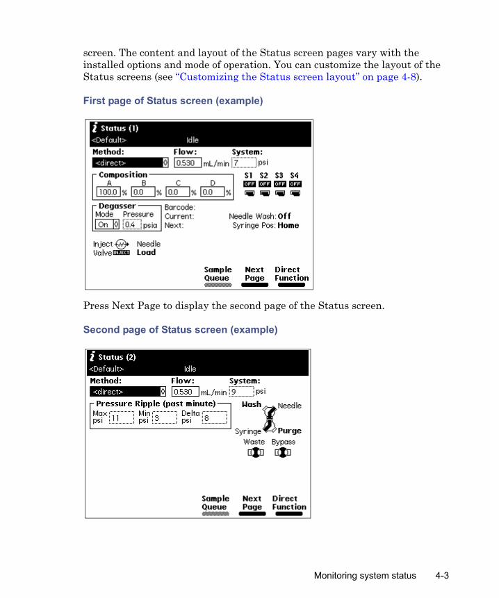
screen. The content and layout of the Status screen pages vary with the installed options and mode of operation. You can customize the layout of the Status screens (see “Customizing the Status screen layout” on page 4-8).
First page of Status screen (example)
Press Next Page to display the second page of the Status screen.
Second page of Status screen (example)
Monitoring system status 4-3

Status screen parametersThe following table describes the parameters in the Status screen pages. The Status column provides the parameter names used in the Status Page Layout dialog box. See “Customizing the Status screen layout” on page 4-8.Notes:
• If you alter the settings for an existing separation method in the Status screen, the Method field changes to <direct>, the separation method name in the Banner area is enclosed within angle brackets (< >), and the current isocratic conditions (with no timed events) are applied.
• The first three parameters (Method, Flow, and System) always appear in the Status screen.
Status screen parameters
Status Parameter Description ValuesMethod Method Indicates the current
separation method. When you change any parameter in the Status screen, this field changes to <direct>, indicating that current operating conditions possibly do not correspond to a stored method. To select a stored method, select the Method field, press Enter, and then select the method from the drop-down list.
All stored separation methods.
Flow Flow Specifies the current flow rate of the solvent management system in mL/min.
0 or 0.010 to 10.000 mL/min.
System System Indicates the current system pressure in kPa, bar, or psi.
Not editable.
4-4 Front Panel Control

Composition Composition Indicates the current solvent composition from combining as many as four solvents as a percentage.Sum of the four solvent reservoirs = 100%.
Each reservoir: 0 to 100%.
Sample heater/cooler
SampleSet
Specifies the user-specified sample compartment temperature in °C.
OFF or 4 to 40 °C.
Current Indicates the current actual sample compartment temperature, in °C.
Not editable.
Column heater or column heater/cooler
Column
Set
Current
Selection
Indicates the temperature and selection of a column.
Indicates the user-specified column temperature in °C.
Indicates the current actual column temperature in °C.Indicates current column (if column selection valve is installed).
OFF or 20°C to 65 °C (OFF or 4°C [or ambient minus 15°C] to 65 °C for column heater/cooler).
Not editable.
List of configured column position names (if column selection valve is installed).
Switches S1, S2, S3, S4
Graphically indicate the status of event switches on the I/O connector.
On or Off
Status screen parameters (Continued)
Status Parameter Description Values
Monitoring system status 4-5

Valves Valves Graphically indicate the position of each of the four valves in the sample management system.
See “Controlling the wash, purge, waste, and bypass valves” on page 8-11.
Wash/Purge 3-way valves:Syringe to Needle,Wash to Needle,Purge to Syringe,Waste/Bypass2-way valves:Open (Waste) andClosed (Bypass)
Degasser Mode Specifies the mode of operation.
On - enabled.Off - disabled.
Pressure Indicates the current vacuum level.
kPa, mbar, psia (not editable).
Ripple Pressure Ripple
Indicates pressure readings in the solvent management system for the most recent minuteMax psi – Maximum pressureMin psi – Minimum pressureDelta psi – Peak-to-peak pressure difference.
Not editable.
Status screen parameters (Continued)
Status Parameter Description Values
4-6 Front Panel Control

Miscellaneous
Syringe Position
Indicates the current position of the syringe.
Empty – Highest position (to refresh the syringe).Home – Default position.Full – Lowest position (to draw in sample).
Needle Wash
Indicates if the needle-wash pump is on.
Not editable.
Sample Indicates the plate and well number of the current injection.
Not editable.
Location Indicates the plate and well number of the sample that is preloaded.
Not editable.
Needle and Inject Valve
Injector Indicates the current position of the needle
Up – Home.Load – In the injection port.Wash – Above the inject port.Well – In a sample well(not editable).
Inject Valve Indicates the current position of the injection valve
Load,Inject,Prime.(not editable)
Status screen parameters (Continued)
Status Parameter Description Values
Monitoring system status 4-7

Sample Queue
When you press the Sample Queue screen key on the Status Screen, the samples sets to be used for the current run are displayed.
Customizing the Status screen layoutEach line in the Status Page Layout dialog box consists of a selection box, the name of the system parameter to be displayed in the Status screen(s), and the
Abs Detector Ch1/2
486/24871 Indicates the current status of one or two Waters 486 or one or both channels of a 2487 detector, if installed.
λ Wavelength 486: 190 to 600nm, 2487: 190 to 700 nm.
Lamp Lamp status, ON or OFF Not editable.AUFS Absorbance Units Full Scale 486: 0.001 to
2.0002487: 0.0001 to 4.0000.
RI Detector 410/24101 Indicates the current status of the Waters 410 or 2410 RI detector, if installed.
Cell Cell temperature Not editable.Col 1 External temperature 1 Not editable.Col 2 External temperature 2 Not editable.
RS-232 Valves2
Address Displays the address of the valve.
0 to 9, or A to F
Position Displays the current position of the valve.
0 to 32
1. These parameters are active only when the separations module is in System Controller mode.
2. This parameter can appear only if RS-232 valves are connected to the separations module.
Status screen parameters (Continued)
Status Parameter Description Values
4-8 Front Panel Control

relative size of the parameter box. By using the screen keys (Raise, Lower), you can specify the order in which the status of each parameter is displayed.The Status screen displays a grid of six units across and three units down. The measurements next to each parameter in the Status Page Layout dialog box specify the size of each parameter box relative to the full grid. The e2795 firmware attempts to fit all enabled parameter boxes on the Status screen in the specified order.
To customize the layout of the Status screen pages:
1. From the Main screen, press Config, More and then Status Layout.
2. On the Status Page Layout dialog box, use the Up/Down arrow keys to select a parameter box .
3. For the selected parameter box, press Enable to display it (the selection box is filled in) or Disable to hide it.Tip: If a parameter box is already enabled, the screen key reads Disable. If a parameter box is disabled, the screen key reads Enable. If the Enable key is shaded, the parameter is not available for your configuration.
4. Press Raise to move the enabled parameter box higher in the display grid. Press Lower to move an enabled parameter box lower in the display grid.Tip: Press Reset Defaults to return to system defaults for the Status screen.
5. Press Apply to save the changes without closing the Status Page Layout dialog box. Result: The Status Page number (1 or 2) appears next to each enabled parameter field in the list. If no page number appears next to an enabled parameter, the Status Page Layout does not allow enough room to display the parameter.
6. Press Close.
Performing direct functions
The following figure outlines the procedure for using the front panel to set up the separations module to perform a direct function.
Performing direct functions 4-9

Steps to setting up a direct control run
To access the direct control functions:
1. Press Menu/Status to display the Status screen (see the figure on page 4-3).
2. Press the Direct Function screen key. Result: A list of direct functions appears.
3. From the list of direct functions, select the function you want to specify, and then press Enter.
4. Follow the instructions for each function, as described in the following sections.
Direct functions
Direct function Description ReferenceDry Prime Opens the flow path (from the
selected solvent reservoir to the prime/vent valve) to replace air with solvent, and then performs a prime.
“Dry priming the system” on page 4-12
Press the Menu/ Status key
The function begins to run
Select the separation method, or enter parameter values in the Status screen
Press the Direct Function screen key
Select the direct function to perform
Enter the function parameters
4-10 Front Panel Control
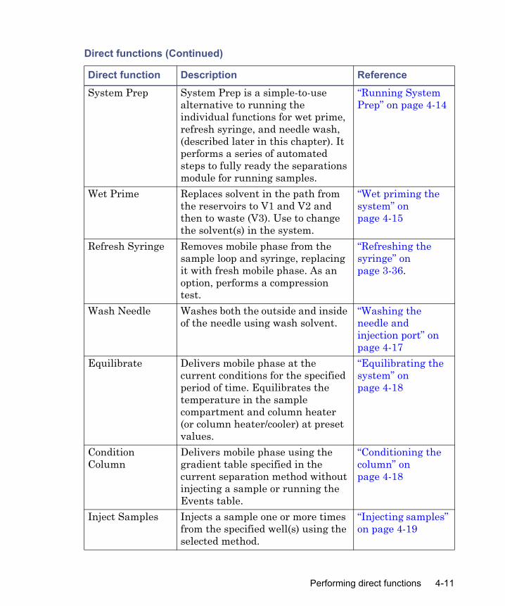
System Prep System Prep is a simple-to-use alternative to running the individual functions for wet prime, refresh syringe, and needle wash, (described later in this chapter). It performs a series of automated steps to fully ready the separations module for running samples.
“Running System Prep” on page 4-14
Wet Prime Replaces solvent in the path from the reservoirs to V1 and V2 and then to waste (V3). Use to change the solvent(s) in the system.
“Wet priming the system” on page 4-15
Refresh Syringe Removes mobile phase from the sample loop and syringe, replacing it with fresh mobile phase. As an option, performs a compression test.
“Refreshing the syringe” on page 3-36.
Wash Needle Washes both the outside and inside of the needle using wash solvent.
“Washing the needle and injection port” on page 4-17
Equilibrate Delivers mobile phase at the current conditions for the specified period of time. Equilibrates the temperature in the sample compartment and column heater (or column heater/cooler) at preset values.
“Equilibrating the system” on page 4-18
Condition Column
Delivers mobile phase using the gradient table specified in the current separation method without injecting a sample or running the Events table.
“Conditioning the column” on page 4-18
Inject Samples Injects a sample one or more times from the specified well(s) using the selected method.
“Injecting samples” on page 4-19
Direct functions (Continued)
Direct function Description Reference
Performing direct functions 4-11

Tip: To run timed events without injecting a sample, select the Inject Samples option from the Direct Functions menu, and enter an injection volume of 0 (see “Injecting samples” on page 4-19).
Dry priming the systemUse the dry prime option to prime the system when the flow path in the solvent management system is dry. See “Preparing the separations module for operation” on page 3-42. Required material30-mL syringe (startup kit)
To dry prime the system:
1. Set up the reservoirs as described in “Installing the degasser vent tubing” on page 2-11.
2. Insert the solvent tubing into the appropriate reservoir(s). Requirement: The detector waste line and the sample loop waste line must drain into an appropriate container.
3. Gently shake the filters in the reservoirs to remove any bubbles that may be trapped.
4. Attach the empty syringe to the prime/vent valve, as shown in the following figure.
5. Open the valve by turning it counterclockwise 1/2 turn.Tip: The syringe does not lock onto the prime/vent valve; hold it in place while you pull on the plunger.
Wash Plungers Washes the plungers to prevent the buildup of precipitates.
“Washing plungers” on page 4-23
Direct functions (Continued)
Direct function Description Reference
4-12 Front Panel Control

Prime/vent valve with syringe
6. Press the Direct Function screen key on the Status screen.
7. Select Dry Prime, and then press Enter.
8. In the Dry Prime dialog box, press the screen key corresponding to the solvent line you want to prime.
9. Withdraw the syringe plunger, pulling solvent through the tubing. Tip: You need to exert force to pull the air and solvent through the system. Continue until you pull all the air through the solvent line and into the syringe.Tip: You need not push the syringe plunger. The draw-off valve is located after the primary piston. Once it is filled with solvent, the primary piston delivers solvent to the accumulator piston and then to the sample management system.
10. Repeat step 8 and step 9 for each solvent line you want to prime, and then close the prime/vent valve.
11. Press a screen key corresponding to the solvent line with which you want to prime the system. Tip: To facilitate purging air from the lines, start the wet prime using the solvent with the lowest viscosity.
12. Specify a duration of 5 minutes and press Continue.
Performing direct functions 4-13
Result: The solvent management system begins to operate. At the end of the priming period, the solvent management system turns off and the separations module enters the idle mode.
13. Run System Prep or wet prime the system.
Running System PrepThe separations module has a direct function for system preparation, labeled System Prep. This function prepares the separations module for operation.System Prep performs these functions:
• After you manually perform a dry prime putting eluent in the line from the reservoirs to the pump heads, System Prep fills the entire flow path of the separations module with fresh eluents, or wash and purge solvents, according to the selected separation method.
• System Prep performs a wet prime of 100% of each solvent used by the method and concludes by setting the separations module at the initial composition. While priming, it also washes the needle and purges the syringe.
• An optional extension of the solvent priming and the syringe purge time can be specified, which is useful when changing solvent or after extended periods of system inactivity.
• When you select the System Prep function immediately after powering up the separations module, a banner at the top of the Status screen reports that the System Prep function requires five minutes for the degasser to condition the eluents before initiating System Prep. The five-minute period posted in the banner decreases incrementally until time zero, and System Prep begins automatically after time zero.
Caution: • To avoid damaging the plunger seals, run System Prep only when
solvent is in the solvent management system’s flow path. If necessary, fill all solvent reservoirs and dry prime the system before you run System Prep.
• To avoid precipitating salts in the separations module, use an intermediate solvent such as water when you change from buffers to high-organic-content solvents. See “Solvent miscibility” on page D-5 for information on solvent miscibility.
4-14 Front Panel Control

Tip: You can access System Prep as a direct function, or run it from a sample set stored in the separations module. You can also run it as a sample list function under remote-control operation by Empower or MassLynx software. When you run System Prep from a sample set or as a sample list function, it adopts the separation method’s parameter values.
Upon initiation, System Prep completes these tasks
1. Wet primes 100% of each solvent specified by the given separation method using a flow rate of 7.0 mL/min. The length of each wet prime is approximately 0.4 minutes. The optional wet prime can be enabled or disabled using the Solvent Change option.
2. Wet primes 100% of each of the solvents specified by the given separation method using a flow rate of 1.0 mL/min (for optimal degasser efficiency).
3. Refreshes the syringe simultaneously with the wet primes until complete using the ratios in the table, below. In all cases, replacement volume is one stroke.
4. Washes the needle and injection port simultaneously with the wet primes until complete, using the wash cycles, injection port wash time, and needle exterior wash time parameters from the selected separation method.
5. Leaves the system at an initial flow rate and composition of the selected separation method.
Wet priming the systemWet prime the system when you change reservoirs or solvents or if the separations module has been idle for some time. Wet priming replaces solvent
Refresh syringe ratios
Solvent status Refresh syringe ratioSolvent Change 10 strokes, 3.75 mL1
1. Based on a standard configuration of a 500-uL syringe.
No Solvent Change 3 strokes, 1.0 mL
Performing direct functions 4-15
in the flow path from the reservoirs to V3 (waste). If the solvent lines are dry, dry prime before continuing (see “Dry priming the system” on page 4-12).
To run the Wet Prime function:
1. In the Status screen’s Composition box, enter 100% for the solvent you use for wet priming. Tip: To facilitate purging air from the lines, start the wet prime using the solvent with the lowest viscosity.
2. On the Status screen, press Direct Function.
3. Select Wet Prime, and then press Enter.
4. Gently shake the filters in the reservoirs to remove any bubbles.
5. In the Wet Prime dialog box, specify the flow rate and duration of the priming (using the composition entered in the Status screen), and then press OK. Result: The solvent management system begins to operate at the end of the specified time period, the solvent management system returns to the previous conditions, and the separations module enters the idle mode.
6. Repeat step 1 through step 5 for each solvent, as appropriate.
Equilibrating solvents in the in-line vacuum degasserWet priming occurs at flow rates that do not allow for thorough solvent degassing. After you perform a wet prime, you must degas the solvent remaining in the degasser chamber lines before solvent flow resumes. To do so, specify a zero flow rate of short duration.
Caution: • To avoid damaging the plunger seals, wet prime only when solvent is
in the solvent management system flow path. If necessary, fill all solvent reservoirs and dry prime the system before you wet prime.
• To avoid precipitating salts in the separations module, use an intermediate solvent such as water when you change from buffers to high-organic-content solvents. See “Solvent miscibility” on page D-5 for information on solvent miscibility.
4-16 Front Panel Control
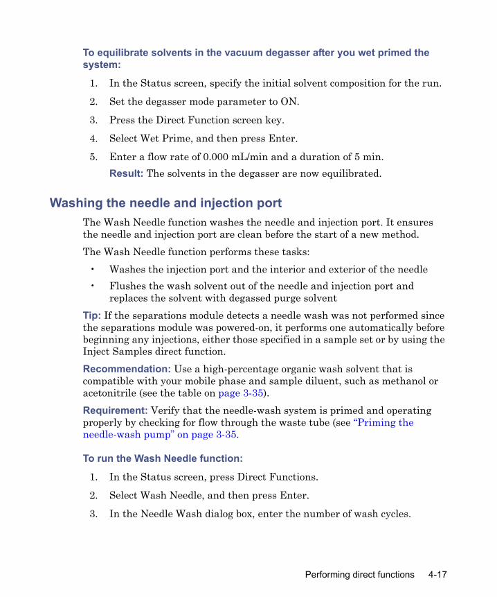
To equilibrate solvents in the vacuum degasser after you wet primed the system:
1. In the Status screen, specify the initial solvent composition for the run.
2. Set the degasser mode parameter to ON.
3. Press the Direct Function screen key.
4. Select Wet Prime, and then press Enter.
5. Enter a flow rate of 0.000 mL/min and a duration of 5 min. Result: The solvents in the degasser are now equilibrated.
Washing the needle and injection portThe Wash Needle function washes the needle and injection port. It ensures the needle and injection port are clean before the start of a new method. The Wash Needle function performs these tasks:
• Washes the injection port and the interior and exterior of the needle• Flushes the wash solvent out of the needle and injection port and
replaces the solvent with degassed purge solventTip: If the separations module detects a needle wash was not performed since the separations module was powered-on, it performs one automatically before beginning any injections, either those specified in a sample set or by using the Inject Samples direct function.Recommendation: Use a high-percentage organic wash solvent that is compatible with your mobile phase and sample diluent, such as methanol or acetonitrile (see the table on page 3-35).Requirement: Verify that the needle-wash system is primed and operating properly by checking for flow through the waste tube (see “Priming the needle-wash pump” on page 3-35.
To run the Wash Needle function:
1. In the Status screen, press Direct Functions.
2. Select Wash Needle, and then press Enter.
3. In the Needle Wash dialog box, enter the number of wash cycles.
Performing direct functions 4-17

4. Enter the amount of time (in seconds) to wash the inject port and the needle exterior in the appropriate fields.
5. Enter the replacement volume of degassed solvent. Tip: Start with 600 μL replacement volume.
6. Press OK to start the wash cycle.Tip: If necessary, press the Stop WashNdl screen key or the Stop Flow key to suspend the wash cycle. When solvent flow stops, press the Abort WashNdl screen key to end the wash needle cycle.Result: At the end of the final wash cycle, the Wash Needle function automatically flushes out the needle-wash solvent and replaces it with degassed purge solvent.
Equilibrating the systemTo equilibrate the HPLC or LC/MS system, the separations module pumps solvent at the initial conditions specified in the Status screen or in the separation method, flushing the flow path of any sample and solvent run at other compositions and preparing the system for the next run.
To run the Equilibrate function:
1. Press Menu/Status to display the Status screen.
2. In the Status screen, specify initial conditions, or, select the separation method that contains the initial conditions at which you want to equilibrate.
3. Press Direct Function.
4. Select Equilibrate, and then press Enter.
5. In the Equilibration dialog box, specify a length of time for equilibrating the system, and press OK.Result: The separations module begins the equilibration procedure. When the system is equilibrated, the separations module enters the idle state. The flow rate remains at the value specified in the Status screen.
Conditioning the columnYou condition the column by running a solvent gradient through it without injecting samples or running the events table. You select a separation method
4-18 Front Panel Control

(see Chapter 5) that contains the gradient parameters, and the separations module runs the gradient method.Tip: To run timed events without injecting a sample, select the Inject Samples option from the Direct Functions menu and enter an injection volume of 0 (see “Injecting samples” on page 4-19).
To condition the column:
1. Press Menu/Status to display the Status screen.
2. In the Status screen, select the Method box, and then select the separation method with which you want to condition the column.
3. Press Direct Function.
4. Select Condition Column, and then press Enter.
5. In the Condition Column dialog box, specify a length of time for conditioning the column that equals or exceeds the duration of the gradient, as defined in the specified separation method (including reequilibration time).
6. Press OK.
Injecting samplesUsing the keypad, you can inject one or more samples from one or more wells in a sample plate. If no separation method is selected, the separations module uses the instrument conditions displayed in the Status screen. You can use gradients and timed events by selecting a separation method in the Method field. The current separation method is displayed in the Banner area. Tip: If you alter the settings for an existing method in the Status screen, the Method field changes to <direct>, the separation method name in the Banner area is enclosed within angle brackets (< >), and the current isocratic conditions (with no timed events) are applied.
To inject samples:
1. Place the prepared sample(s) or vial(s) into a plate, and then insert the plate in the sample compartment (see “Loading the sample plates” on page 3-38).
2. Close the sample compartment door.
Performing direct functions 4-19

3. In the Status screen, enter the initial conditions. Alternative: Select Method, and then select the separation method that contains the conditions to perform the injection.
4. Press Direct Function.
5. Select Inject Samples, and then press Enter.
6. In the Inject Samples dialog box, enter a value in each parameter box (see the table, below), and then press Enter.
7. Press OK.
Inject Samples dialog box parameters
Parameter Description Value rangeLocation Specifies the plate carrier
location1 to 4
Type Specifies the plate type One of as many as 15 (see “Configuring plate types” on page 3-19)
Well(s) Specifies the well number or range from which you want to make injections.Alternative: Press the Plate screen key to select one or more wells using the Well Selector (see “Selecting wells for making injections” on page 4-21).Tip: When entering a well range, use the “•” key to separate entries. For example, to inject samples from wells 1 through 20, enter 1.20.
Depending on plate type, 1 to 24, 48, 96, or 384
Inject(s) Specifies the number of injections per well
1 to 99
4-20 Front Panel Control
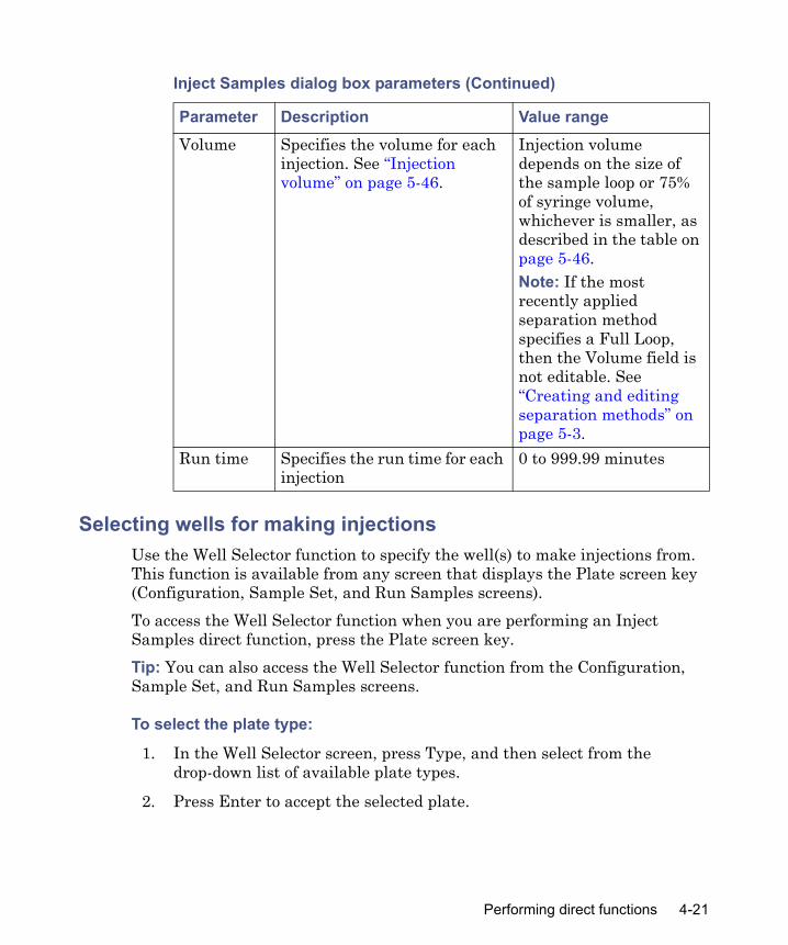
Selecting wells for making injectionsUse the Well Selector function to specify the well(s) to make injections from. This function is available from any screen that displays the Plate screen key (Configuration, Sample Set, and Run Samples screens).To access the Well Selector function when you are performing an Inject Samples direct function, press the Plate screen key. Tip: You can also access the Well Selector function from the Configuration, Sample Set, and Run Samples screens.
To select the plate type:
1. In the Well Selector screen, press Type, and then select from the drop-down list of available plate types.
2. Press Enter to accept the selected plate.
Volume Specifies the volume for each injection. See “Injection volume” on page 5-46.
Injection volume depends on the size of the sample loop or 75% of syringe volume, whichever is smaller, as described in the table on page 5-46.Note: If the most recently applied separation method specifies a Full Loop, then the Volume field is not editable. See “Creating and editing separation methods” on page 5-3.
Run time Specifies the run time for each injection
0 to 999.99 minutes
Inject Samples dialog box parameters (Continued)
Parameter Description Value range
Performing direct functions 4-21

To select a single well:
1. In the Well Selector screen, press Set by Number, and then enter the well number. Alternative: Use the arrow keys to move to the specific well you want to specify.
2. Press • to set the selected well, or press Clear to clear the selected well.Tips:• To switch a well to its opposite state (selected to deselected or vice
versa), press Enter.• To select all the wells on the selected plate, press Select All. The key
name changes to Clear All.• To deselect all selected wells on the selected plate, press Clear All.
The key name changes to Select All.
To select a group of wells (two or more) in a rectangular area of the selected plate:
1. In the Well Selector screen, press Start Group.
2. Use the arrow keys to outline the group of wells.
3. Press • to set all the selected wells, or press Clear to clear the selected wells. Tip: To switch each well in a group to its opposite state (selected to deselected or vice versa), press Enter.
4. If the separations module is configured for printing (see “RS-232 connections” on page 2-27), press Print to print the Well Selector screen currently displayed.
5. Press OK to return to the Inject Samples dialog box or the sample set table.
Notes:• When a collection contains noncontiguous wells, the wells are indicated
in the well field of the Inject Samples dialog box or the Sample Set table by the total number of wells in square brackets ([…]). See “Creating and editing sample sets” on page 5-36, for more information.
• The separations module provides predefined as well as custom plate types. For more information, see “Configuring plate types” on page 3-19.
4-22 Front Panel Control

Washing plungersUse the plunger washing procedure to prevent the build-up of precipitates on the pump plungers (which can damage the high pressure seals) by washing them with seal wash solvent.Tip: The plunger washing procedure starts when there has been zero flow for the time period you specified in the No Flow Shutdown procedure (see “Auto Shutdown” on page 3-17).Wash the plungers whenever:
• The system is going to be idle for a long time• Before running the system after it has been idle• When running the system with salt buffers
To wash the plungers:
1. Press the Direct Function screen key. The Direct Functions list appears.
2. Select Wash Plungers, and then press OK. The Wash Plungers procedure does the following:
a. Switches the injector valve to the Prime position.
b. Increases the seal wash period to 1 second and turns on the seal wash pump.
c. Fills the accumulator and primary with the current solvent composition.
d. Slowly empties the accumulator and primary, allowing the seal wash solvent to wash the plungers.
e. Repeats step c and step d.
f. Turns off the seal wash pump and returns the seal wash period to its previous value.
g. Switches the injector valve back to its previous position.
Performing direct functions 4-23

4-24 Front Panel Control
5 Creating and Editing Separation Methods and Sample Sets
Contents
Topic PageOverview 5-2Creating and editing separation methods 5-3Setting separation method parameters 5-7Creating and editing sample sets 5-36
5-1

Overview
This chapter explains how to create and edit the separations methods and sample sets that allow you to make automatic runs when the separations module is in a standalone mode. If your separations module is configured for Empower or MassLynx software control, refer to your Empower or MassLynx documentation for instructions on making automatic runs.Chapter 6 explains how to perform an automatic run in a standalone or remote control mode.You can create and store the separation methods, sample sets, and sample templates with which you make automatic runs when the separations module is in the standalone System Controller mode. You can store as many as 60 methods in the internal memory of the separations module. When the number of stored methods approaches 60, the maximum, the time required to create and save methods increases from a few seconds to over 30 seconds. When 60 methods are stored, a warning message appears indicating that memory capacity is reached.The separations module supports three types of tools for controlling automatic runs in a standalone mode:
• Separation methods• Sample sets• Sample templates
Separation methodsThe separations module uses and stores programs that can automatically run a separation method, which consists of these time-based and nontime-based conditions that influence the separation:
• Mobile phase composition and flow rate• Sample temperature• Column temperature• I/O parameters
When you run a separation method on another, identically configured separations module in an Alliance® System, you can reproduce identical separations.
5-2 Creating and Editing Separation Methods and Sample Sets
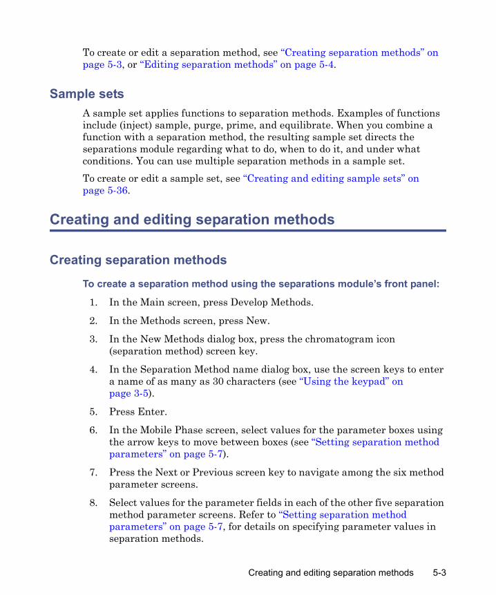
To create or edit a separation method, see “Creating separation methods” on page 5-3, or “Editing separation methods” on page 5-4.
Sample setsA sample set applies functions to separation methods. Examples of functions include (inject) sample, purge, prime, and equilibrate. When you combine a function with a separation method, the resulting sample set directs the separations module regarding what to do, when to do it, and under what conditions. You can use multiple separation methods in a sample set.To create or edit a sample set, see “Creating and editing sample sets” on page 5-36.
Creating and editing separation methods
Creating separation methods
To create a separation method using the separations module’s front panel:
1. In the Main screen, press Develop Methods.
2. In the Methods screen, press New.
3. In the New Methods dialog box, press the chromatogram icon (separation method) screen key.
4. In the Separation Method name dialog box, use the screen keys to enter a name of as many as 30 characters (see “Using the keypad” on page 3-5).
5. Press Enter.
6. In the Mobile Phase screen, select values for the parameter boxes using the arrow keys to move between boxes (see “Setting separation method parameters” on page 5-7).
7. Press the Next or Previous screen key to navigate among the six method parameter screens.
8. Select values for the parameter fields in each of the other five separation method parameter screens. Refer to “Setting separation method parameters” on page 5-7, for details on specifying parameter values in separation methods.
Creating and editing separation methods 5-3

9. To save the new method, press Exit, and when prompted to save, press Yes.
Editing separation methods
To edit an existing separation method using the separations module’s front panel:
1. In the Main screen, press Develop Methods.
2. In the Methods screen, select the separation method and press Edit. Tip: If the separation method is locked, the Edit screen key is unavailable. To unlock a locked separation method, see “Locking/unlocking separation methods” on page 5-5.
3. Enter the new parameter values in the appropriate screens (see “Setting separation method parameters” on page 5-7).
4. To save the method, use one of these procedures:• Under its current name, press Exit, and when prompted to save,
press Yes.• Under a new name, press Exit, and when prompted to save, press
Save as. The separations module automatically creates a new method name by adding an extension to the original method name.Alternative: Use the alphabetic screen keys to change the name (see “Using the keypad” on page 3-5), and then press Enter.
5. To exit without saving the changes, press Exit. When prompted to save, press No. To return to the method without entering any changes, press Cancel.
Copying and editing separation methods
To copy and then edit an existing separation method, leaving the original method unchanged:
1. In the Main screen, press Develop Methods.
2. In the Methods screen, select the separation method and press Copy.Tip: To avoid duplicate file names, the separations module automatically appends an extension to the existing file name.
5-4 Creating and Editing Separation Methods and Sample Sets

3. Press Enter to accept the default method name, or use the alphabetic screen keys to enter a new name (see “Using the keypad” on page 3-5), and then press Enter.
4. Enter new parameter values in the appropriate parameter screens (see “Setting separation method parameters” on page 5-7).
5. To save the method, press Exit then Yes. To exit without saving the method, press No. To return to the method without entering any changes, press Cancel.
Locking/unlocking separation methods
Locking a separation method
Locking a method prevents unauthorized changes to the method.
To lock a separation method:
1. In the Main screen, press Develop Methods.
2. In the Methods screen, select the method and press Lock.
3. Enter a password of as many as 30 alphanumeric characters (see “Using the keypad” on page 3-5), and then press Enter. Result: The method is locked and cannot be changed, deleted, or renamed until it is unlocked (see below).Tip: When you copy a locked method and save it with a new name, the copy is not locked.
4. Record the password and keep it in a safe place.
Unlocking a separation method
To unlock a separation method:
1. In the Main screen, press Develop Methods.
2. In the Methods screen, select the separation method and press Unlock.
3. Enter the password and press Enter.
Creating and editing separation methods 5-5

Renaming, viewing, and deleting separation methods
Renaming a separation method
To rename a separation method:
1. In the Methods screen, select a separation method to rename.
2. Press More until the Rename screen key appears, and then press Rename.
3. In the Change to Method Name dialog box, enter the new method name using the alphanumeric screen keys (see “Using the keypad” on page 3-5), and then press Enter.
Viewing a separation method
To view a separation method:
1. In the Methods screen, select a separation method to view.
2. Press More until the View screen key appears, and then press View. Result: The first parameter screen (Mobile Phase screen) for the selected method appears.
3. Press Next or Previous to view the other five parameter screens for the selected method.
Deleting a separation method
You can delete separations methods using one of these keys:• Delete screen key• Delete Methods screen key
Restriction: You cannot delete the Default method or any locked method.
To delete a separation method using the Delete screen key:
1. In the Methods screen, select a separation method to delete.
2. Press Delete.
3. In the Deleting Method dialog box, press Yes.
5-6 Creating and Editing Separation Methods and Sample Sets

To delete a separation method using the Delete Methods screen key:
1. In the Methods screen, press More until the Delete Methods screen key appears.
2. Press Delete Methods.
3. In the Delete Methods dialog box, for each separation method you want to delete, use the arrow keys to select the method, and then press Select Method. Tip: To select all methods except the previously selected method(s), press Invert Choices. To clear all selected methods on the Delete Methods screen, press Clear Choices.
4. Press Delete Now.
Setting separation method parameters
You enter separation method parameters in six different screens, sequenced as shown in the table, below. Press the Next or Previous screen key to move from one method parameter screen to another. Tip: The “pie” icon between the Next and Previous screen keys indicates your location among the six parameter screens.
Separation method parameter screens
Sequence number Screen name Reference
1 Mobile Phase “Setting mobile phase parameter values” on page 5-8
2 Sample “Setting sample parameter values” on page 5-14
3 Autosampler “Setting autosampler parameter values” on page 5-16
4 Column “Setting column parameter values” on page 5-25
5 I/O “Setting I/O parameter values” on page 5-27
6 Detectors “Setting detector parameters” on page 5-31
Setting separation method parameters 5-7

Notes:• Parameter boxes that are not editable for the option you select are
surrounded by a dotted line. • As you change values on the parameter screens, the word “modified”
appears in parentheses next to the method name. • When you finish entering or changing values on all six parameter
screens, press Exit. At the Save prompt, press the Yes, Save As, No, or Cancel screen keys as appropriate (see “Editing separation methods” on page 5-4).
Setting mobile phase parameter valuesThe Mobile Phase screen appears when you create a new separation method, view a locked separation method using the View screen key, or edit a separation method.
To enter parameter values in the Mobile Phase screen:
1. Press Next or Prev as needed to display the Mobile Phase screen.
2. Enter or select values in the boxes, as appropriate. The following table describes the parameters and screen keys in the Mobile Phase screen.
Mobile Phase screen parameters
Parameter Function Value rangeInitial Flow Specifies the initial flow rate of
the method. For isocratic operation, this is the flow rate for the entire separation.
0.000 and 0.010 to 10.000 in 0.001-mL/min increments(typically 50 μL to 5 mL/min)
Initial Composition
Specifies the initial composition of the mobile phase. The sum of the four fields must equal 100%. (Enter, change, or delete solvent names using the Labels screen key. See “Labels” elsewhere in this table.)
0 to 100.0 in 0.1% increments
5-8 Creating and Editing Separation Methods and Sample Sets

Alarms: Min Specifies the system pressure (set in psi, bar, or kPa) below which the alarm condition (selected in the adjacent box) is executed. To enable access to the Pressure fields, set the alarm parameter to any selection other than “Disable.”
0 to 4500 in 1-psi increments, 0 to 310 bar in 1-bar increments, or 0 to 31025 kPa in 1-kPa increments (see “Status screen parameters” on page 4-4).To configure the alarm responses, see “Setting alarm responses” on page 5-12.
Alarms: Max Specifies the system pressure (set in psi, bar, or kPa) above which the alarm condition (selected in the adjacent box) is executed. Use to detect problems with method conditions and to protect your column from overpressure.
0 to 5000 in 1-psi increments, 0 to 344 bar in 1-bar increments, or 0 to 34473 kPa in 1-kPa increments (see “Status screen parameters” on page 4-4).To configure the alarm responses, see “Setting alarm responses” on page 5-12.
Alarms: Bubble Detect
Specifies the response to occur when the solvent management system detects a bubble in the flow path.
See “Setting alarm responses” on page 5-12.
Mobile Phase screen parameters (Continued)
Parameter Function Value range
Setting separation method parameters 5-9
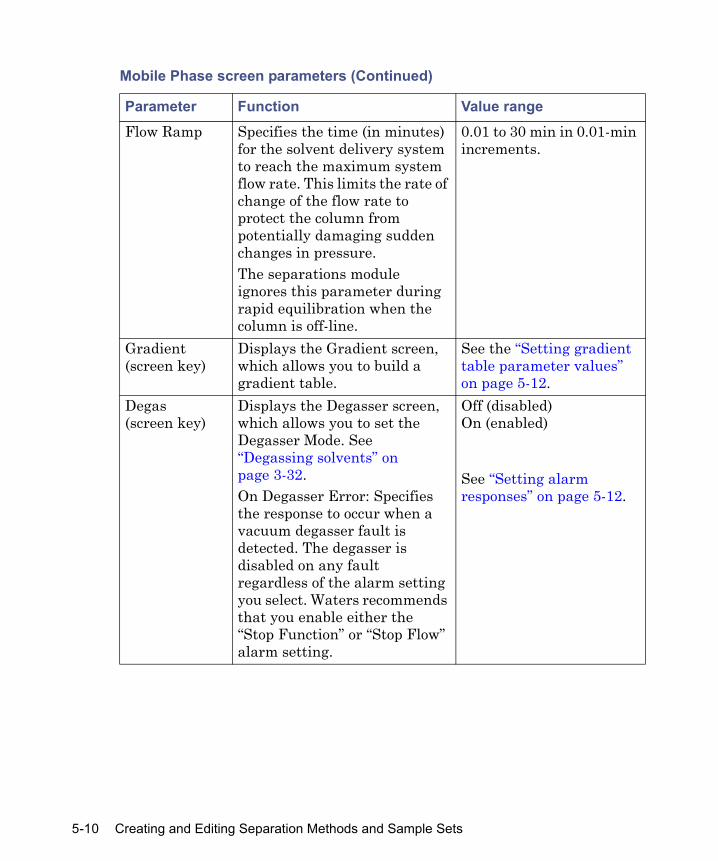
Flow Ramp Specifies the time (in minutes) for the solvent delivery system to reach the maximum system flow rate. This limits the rate of change of the flow rate to protect the column from potentially damaging sudden changes in pressure.The separations module ignores this parameter during rapid equilibration when the column is off-line.
0.01 to 30 min in 0.01-min increments.
Gradient(screen key)
Displays the Gradient screen, which allows you to build a gradient table.
See the “Setting gradient table parameter values” on page 5-12.
Degas(screen key)
Displays the Degasser screen, which allows you to set the Degasser Mode. See “Degassing solvents” on page 3-32.On Degasser Error: Specifies the response to occur when a vacuum degasser fault is detected. The degasser is disabled on any fault regardless of the alarm setting you select. Waters recommends that you enable either the “Stop Function” or “Stop Flow” alarm setting.
Off (disabled)On (enabled)
See “Setting alarm responses” on page 5-12.
Mobile Phase screen parameters (Continued)
Parameter Function Value range
5-10 Creating and Editing Separation Methods and Sample Sets
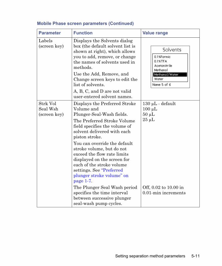
Labels(screen key)
Displays the Solvents dialog box (the default solvent list is shown at right), which allows you to add, remove, or change the names of solvents used in methods. Use the Add, Remove, and Change screen keys to edit the list of solvents.A, B, C, and D are not valid user-entered solvent names.
Strk VolSeal Wsh (screen key)
Displays the Preferred Stroke Volume and Plunger-Seal-Wash fields. The Preferred Stroke Volume field specifies the volume of solvent delivered with each piston stroke.You can override the default stroke volume, but do not exceed the flow rate limits displayed on the screen for each of the stroke volume settings. See “Preferred plunger stroke volume” on page 1-7.The Plunger Seal Wash period specifies the time interval between successive plunger seal-wash pump cycles.
130 µL - default100 µL50 µL 25 µL
Off, 0.02 to 10.00 in 0.01-min increments
Mobile Phase screen parameters (Continued)
Parameter Function Value range
Setting separation method parameters 5-11

Setting alarm responses
During operation, the separations module records and reports errors according to the alarm responses you specify. Each configurable alarm can produce one of five user-selected responses (see the table, below).
Setting gradient table parameter values
The gradient table allows you to make time-based changes to the composition or flow rate of the mobile phase during a run. You can program as many as 25 rows in the gradient table.
To set parameter values in the Gradient table:
1. In the Mobile Phase screen, press Gradient.
2. In the Gradient screen, enter values in the gradient table as appropriate. The following table describes the parameters in the gradient table. Tip: Use the Overview, Insert Row, Delete Row, Sort by Time, Copy Down, More, Reset Table, and Print screen keys as appropriate.
Alarm responses
Alarm response FunctionDisable All alarm response reporting is disabled.Log Quietly The error is entered into the error log without
alerting the operator.Alert User The error is entered into the error log and the
operator is alerted with a dialog box.Stop Funct The error is entered into the error log, the
operator is alerted with a dialog box, and operation is suspended at the end of the current function. You can abort or resume the operation of the sample set by pressing the appropriate screen key.
Stop Flow The error is entered into the error log, the operator is alerted with a dialog box, the current function is suspended, and solvent flow is stopped.
5-12 Creating and Editing Separation Methods and Sample Sets

3. Press Exit to save the Gradient table.The following table describes the parameters in the Gradient table.
Gradient table parameters
Parameter Function Value rangeTime Specifies the time after the start of
the run at which the change is to occur. (INIT is allowed only in the first row of this table.)
INIT, 0.00 to 999.99 in 0.01 minute increments
Flow Sets the flow rate of the solvent delivery system.
0.000 and 0.010 to 10.000 in 0.001 mL/min increments
%A, %B, %C, %D
Sets the proportion of each solvent in the mobile phase. The sum of these four fields must equal 100%.
0 to 100 in 0.1% increments
Curve Sets the rate at which the solvent is to change to the new proportions and/or flow rates (see “Gradient Curves”, below).
Select the desired gradient curve from the list of profiles, or select the curve number (1 – 11) by pressing the appropriate numeric key. Tip: Press “0” for curve 10 and “.” for curve 11.
Overview (screen key)
Displays a time-ordered summary of the events in the gradient, detector, and timed events tables.
N/A
Insert Row (screen key)
Inserts a row above the current row. N/A
Delete Row (screen key)
Deletes the current row. N/A
Sort by Time (screen key)
Sorts the rows based on time. N/A
Setting separation method parameters 5-13

Gradient curves
The figure, below presents a visual model of the gradient curve for each of the gradient curve values you can specify in the Gradient table.
Curve shapes for gradient profiles
Setting sample parameter values
To enter parameter values in the Sample screen:
1. Press Next or Prev as needed to display the Sample screen.
2. Enter or select values in the Sample screen. The following table describes the parameters in the Sample screen.
Copy Down (screen key)
Copies the contents of the current table cell into subsequent cells in the column.
N/A
Reset Table(screen key)
Clears the table. N/A
Print (screen key)
Prints the gradient table. N/A
Gradient table parameters (Continued)
Parameter Function Value range
2 3 4 5
6
8 9 10 117
1
Start End
Initial conditions
Final conditions
Time
100%
0%
5-14 Creating and Editing Separation Methods and Sample Sets
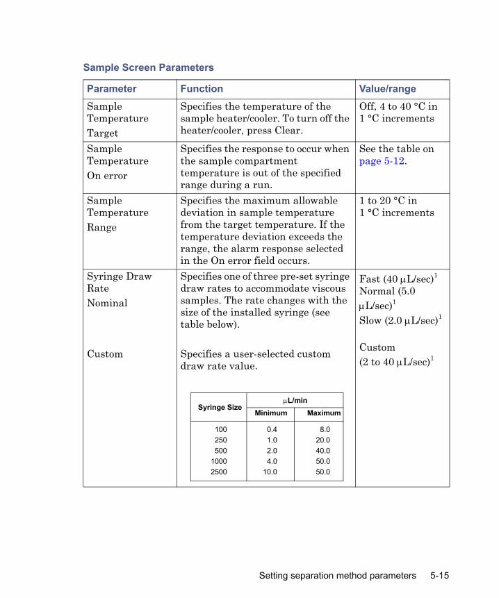
Sample Screen Parameters
Parameter Function Value/rangeSample TemperatureTarget
Specifies the temperature of the sample heater/cooler. To turn off the heater/cooler, press Clear.
Off, 4 to 40 °C in 1 °C increments
Sample TemperatureOn error
Specifies the response to occur when the sample compartment temperature is out of the specified range during a run.
See the table on page 5-12.
Sample TemperatureRange
Specifies the maximum allowable deviation in sample temperature from the target temperature. If the temperature deviation exceeds the range, the alarm response selected in the On error field occurs.
1 to 20 °C in1 °C increments
Syringe Draw RateNominal
Custom
Specifies one of three pre-set syringe draw rates to accommodate viscous samples. The rate changes with the size of the installed syringe (see table below).
Specifies a user-selected custom draw rate value.
Fast (40 μL/sec)1
Normal (5.0 μL/sec)1
Slow (2.0 μL/sec)1
Custom (2 to 40 μL/sec)1
Syringe SizeμL/min
Minimum Maximum
100250500
10002500
0.41.02.04.0
10.0
8.020.040.050.050.0
Setting separation method parameters 5-15

Setting autosampler parameter values
To enter parameter values in the Autosampler screen:
1. Press Next or Prev as needed to display the Autosampler screen.
2. In the Autosampler screen, enter or select values as appropriate.
Depth(Needle Depth Offset)
Adjusts the depth of the needle tip to accommodate sedimented sample or nonstandard wells. A value of 0 corresponds to the bottom of the well. A value of 10 corresponds to 10 mm from the bottom of the well.
0 to 20 in 1-mm increments
1. The specified syringe draw rates are for the standard 500-μL syringe. The rates correspond-ing to Fast, Normal, and Slow automatically change in proportion to the syringe size entered in the Configuration screen (see “Setting configuration parameters” on page 3-11).
Sample Screen Parameters (Continued)
Parameter Function Value/range
5-16 Creating and Editing Separation Methods and Sample Sets

The following table describes the parameters in the Autosampler screen.
Autosampler parameters
Parameter Function Value/rangeInjection mode
Specifies one of three injection modes:• Sequential – Sample aspiration and
loop fill occur at the start of each injection cycle, after completion of the previous injection.
• Parallel – Sample aspiration and loop fill occur concurrently with other separation method functions for higher throughput (for more information, see “Setting up for high-throughput operation” on page 6-9).1
• Manual – For use with a manual injector valve. During manual injections, the internal autosampler and injector valve are disabled (as are their parameters in the separation method editor). To signal the start of a manual injection, a sequence of high (load) and then low (inject) must be sent through the Hold Inject 2 analog inputs.
Sequential
Parallel
Manual
Loop option Specifies one of these methods for placing sample in the sample loop: • Full loop – Does not allow you to
control the injection volume in the Sample Set Editor.
• Partial loop – Allows you full control of the injection volume in the Sample Set Editor, including the option to revert to Full-loop operation.
Tip: Full-loop injections provide the best peak area reproducibility.
Full
Partial
Setting separation method parameters 5-17

Full-loop (overfill)
Specifies the excess volume (expressed as a multiple of the sample loop volume) of sample drawn when you select the Full-loop option (see above), or when you override the Partial-loop option in the Sample Set Editor.
1.0 to 99.9 × in 0.1 × incrementsDefault = 4.0×
Restriction: After saving an instrument method with a full-loop injection mode and a designated number of loop overfills, you cannot make partial-loop injections in Run Samples using that instrument method. Waters recommends naming instrument methods to designate them as either full- or partial-loop methods.
Pre-column (volume)
Specifies the volume of mobile phase delivered to the system after the gradient starts, but before an injection is made.Recommendations: • Use this parameter when you choose a
method from a system whose delay volume is smaller than that of the separations module.
• You can also use this parameter to reduce the delay volume of the separations module for narrow or microbore columns or for high-throughput separations, because the sample is held in the sample loop (if desired) until the gradient front reaches the sample loop.
0.0 to 10000.0 in 0.1-µL increments
Autosampler parameters (Continued)
Parameter Function Value/range
5-18 Creating and Editing Separation Methods and Sample Sets

Loop off-line When the Parallel Injection mode option (see above) is selected, specifies the time after an injection when the next sample is preloaded into the sample loop.Notes:• Preloading the sample into the loop can
result in a small decrease in injection-to-injection cycle time.
• The values of Off and 0.00 are equivalent and ensure that the next sample is not preloaded into the sample loop. Values greater than 0.00 and less than or equal to the method run-time will cause the next sample to be preloaded into the sample loop at the given time. However, the time entered must not be less than the time needed for the current sample to leave the sample loop (based on the size of the sample loop and the current flow rate).
• In Sequential mode, there is no “pre-load” of sample, but the loop can be brought off-line to achieve a decrease in delay volume during the separation.
Off, 0.00 to 999.99 in 0.01-min increments
Post-run delay
Specifies the time after a run that a data system is processing run data. During the delay, the separations module can complete sample management functions: needle wash and purge, sample aspiration, and loop loading (but not injecting).
0 to 999.99 in 0.01-min increments
Autosampler parameters (Continued)
Parameter Function Value/range
Setting separation method parameters 5-19

Aspirate Air
Pre-sample
Post-sample
Specifies a volume of air (air gap) aspirated into the holding loop to minimize sample diffusion. Specifies aspiration of air before the sample is in the needle.Specifies aspiration of air after the sample is in the needle.
Recommendation: To minimize sample diffusion, incorporate air gaps (3 to 5 μL), pre- and post-sample. These “air gaps” can enhance area precision, but are not recommended for all LC/MS applications.
0 to 10.0 in 0.1-μL increments0 to 10.0 in 0.1-μL increments
Seek well bottom
Never – The needle does not attempt to detect the well bottom.On Plate Change – The needle detects the well bottom on the first injection from each plate.On every inject – The needle detects the well bottom on each injection.After detecting the well bottom, its location is stored for use in all subsequent injections, until the plate changes, or the next seek well bottom is performedRestriction: Due to variations in dimensions, do not use the Seek Well Bottom feature with thin-bottom glass inserts (such as part number 186000349) or with the two microcentrifuge sample container plates (part numbers 405000560 and 405000772).
Never
On plate change
On every inject
Autosampler parameters (Continued)
Parameter Function Value/range
5-20 Creating and Editing Separation Methods and Sample Sets
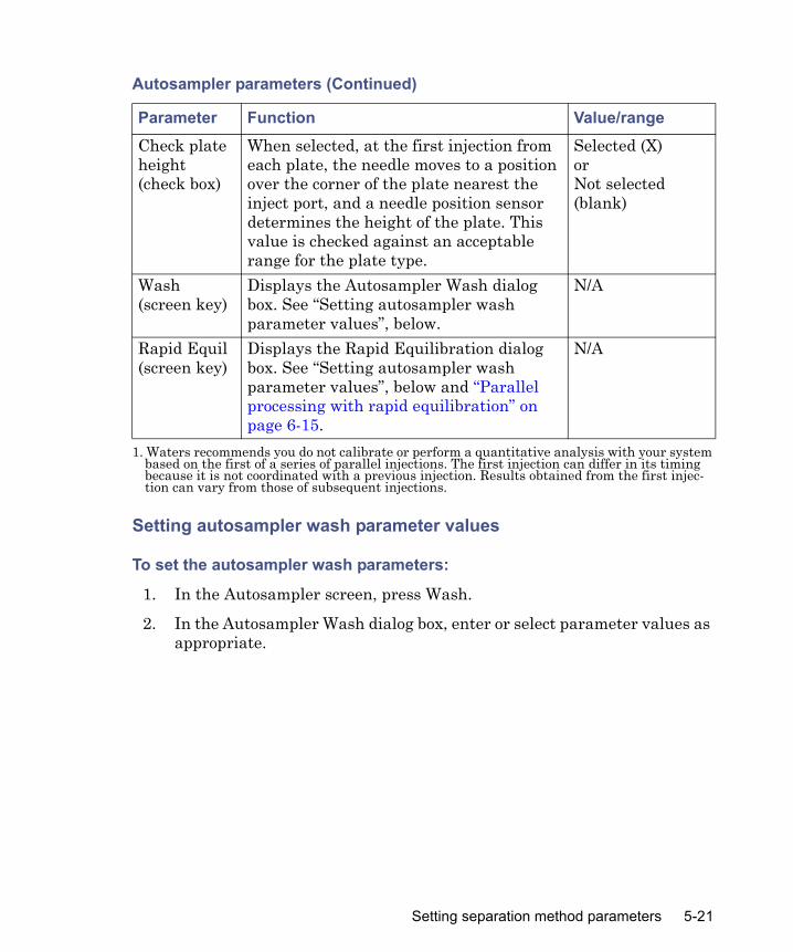
Setting autosampler wash parameter values
To set the autosampler wash parameters:
1. In the Autosampler screen, press Wash.
2. In the Autosampler Wash dialog box, enter or select parameter values as appropriate.
Check plate height (check box)
When selected, at the first injection from each plate, the needle moves to a position over the corner of the plate nearest the inject port, and a needle position sensor determines the height of the plate. This value is checked against an acceptable range for the plate type.
Selected (X)orNot selected (blank)
Wash (screen key)
Displays the Autosampler Wash dialog box. See “Setting autosampler wash parameter values”, below.
N/A
Rapid Equil(screen key)
Displays the Rapid Equilibration dialog box. See “Setting autosampler wash parameter values”, below and “Parallel processing with rapid equilibration” on page 6-15.
N/A
1. Waters recommends you do not calibrate or perform a quantitative analysis with your system based on the first of a series of parallel injections. The first injection can differ in its timing because it is not coordinated with a previous injection. Results obtained from the first injec-tion can vary from those of subsequent injections.
Autosampler parameters (Continued)
Parameter Function Value/range
Setting separation method parameters 5-21

The following table describes the autosampler wash parameters.
Autosampler Wash Parameters
Parameter Function Value/rangeWash SolventLabel
Specifies the wash solvent from the Solvents drop-down list (example shown at right). To add or delete a solvent in the Solvents list, press Labels, and then add or delete as appropriate.
Frequency Specifies when a needle wash is to occur.
Every injectEvery wellNever
Cycles Specifies the number of wash cycles to be performed at each wash
0 to 9 in 1 cycle increments
Inject Port Specifies the number of seconds to wash the injection port
0 to 9999 in 1 secondincrements. Default = 6
Needle Exterior Specifies the number of seconds to wash the exterior of the needle
0 to 9999 in 1 secondincrements. Default = 15
Purge SolventLabel
Specifies the purge solvent from the Solvents drop-down list (example shown at right). To add or delete a solvent in the Solvents list, press Labels, and then add or delete as appropriate.
5-22 Creating and Editing Separation Methods and Sample Sets

3. Press OK.Tip: By default, the wash sequence is set to Wash-Purge. The alternative is the Purge-Wash-Purge sequence that performs an additional purge of the syringe, prior to the Needle-Wash (see “Setting the wash sequence” on page 3-32).
Setting rapid equilibration parameter values
To set rapid equilibration parameter values:
1. In the Autosampler screen, press Rapid Equil.
2. In the Rapid Equilibration dialog box, enter or select parameter values for the displayed boxes.
Purge SolventReplacement Volume
Specifies the volume (in μL) needed to replace old sample management system solvent with fresh degassed purge solvent
0 to 9999 in 1-μL increments
Sequence Specifies the wash sequence.Selecting Purge-Wash-Purge causes an additional purge of the syringe, before the needle wash. See “Setting the wash sequence” on page 3-32.
Wash-Purge (default)
Purge-Wash-Purge
Autosampler Wash Parameters (Continued)
Parameter Function Value/range
Setting separation method parameters 5-23

The following table describes the Rapid Equilibration parameters.
Rapid equilibration parameters
Parameter Function Value/rangePath Specifies the flow path
for rapid equilibration
When the 3-column selection valve is installed at Waters, Position 2 is used for waste.
Off – No rapid equilibrationNo change – Uses the same path as previously specifiedInjector waste – Directs flow to waste through the injection valve• Position 1 – Directs flow out
through Position 1 of the column selection valve (if installed)
• Position 2 – Directs flow out through Position 2 of the column selection valve (if installed)
• Position 3 – Directs flow out through Position 3 of the column selection valve (if installed)
• Position 4 to 6 – Directs flow out through Positions 4 to 6 of a 6-column selection valve (if installed)
Flow Specifies the system equilibration flow rate
0.010 to 5.000 mL/minin 0.001 mL/min increments
Duration Specifies the system equilibration time
0.00 to 999.99 minin 0.01 min increments
Column re-equilibration
Specifies the length of time following system equilibration to reequilibrate the column.See the table on page 6-20.
0.00 to 999.99 minin 0.01 min incrementsDefault value – 5.00 min
5-24 Creating and Editing Separation Methods and Sample Sets

3. Press OK. Tip: For more information on parallel processing with rapid equilibration, see “Setting up for high-throughput operation” on page 6-9.
Setting column parameter values
To enter parameter values in the Column screen:
1. Press Next or Prev to display the Column screen.
2. In the Column screen, enter or select parameter values, as appropriate. The following table describes the Column screen parameters.
Column parameters
Parameter Function Value/rangeColumn Temperature Target
Sets the temperature of the column heater or column heater/cooler (if installed). To turn off the column heater or column heater/cooler, press the Clear key.
Column heater: 20 °C (or 5 °C above ambient) to 65 °C
Column heater/cooler: 4 °C (or ambient minus 15 °C) to 65 °C
Column TemperatureOn error
Specifies the response that occurs when the column temperature is outside the specified range.
See the table on page 5-12.
Column TemperatureRange
Sets the maximum allowable deviation in column temperature from the target temperature. If the temperature deviation exceeds the range, the alarm response selected in the On error field occurs.
1 to 20 °C in 1 °C increments
Setting separation method parameters 5-25

Setting column information parameter values
To set column information parameter values:
1. In the Column screen, press Column Info. Tip: The Column Information dialog box shows three positions for the 3-column selection valve, six positions for the 6-column selection valve, and two positions for the Column Regeneration Valve (see “Column selection valves” on page 1-24).
Column Selection3-ColumnValve
Selects a column position if a 3-column selection valve is installed.
Tip: Select No Change when you link methods in a sample set and do not want to change the column from the previous method.
Position 1 through Position 3, or No Change
6-ColumnValve
Selects a column position if a 6-column valve is installed.
Position 1 through Position 6, or No Change
Column SelectionColumnRegenerationValve
Selects a column position if a column regeneration valve is installed.
See “Setting up two-column regeneration” on page 5-27.
Column Info (screen key)
Allows you to enter or modify the column information for each column position.
30 characters each
Column Information
Displays the column information for the column position you select using the Column Info screen key.
N/A
Equilibration When a change in column selection occurs at run time, specifies the amount of time that the separations module operates at initial conditions before performing an injection.
0 to 999.99 min
Column parameters (Continued)
Parameter Function Value/range
5-26 Creating and Editing Separation Methods and Sample Sets
2. In the Column Information dialog box, select a column position, and then press Modify.
3. Enter the new information, as many as 30 characters for each column position, in the Column Switch Position information box (see “Using the keypad” on page 3-5), and press Enter.
4. Press OK.
Setting up two-column regenerationThe automated column regeneration valve operates under separations module standalone control and via remote control, such as with Empower or Masslynx software (see your remote control software documentation for details). In standalone mode, the separations module controls the 2-column regeneration valve through these inputs on the Column page of the separation method:
• 1 – Places column 1 in the flow path• 2 – Places column 2 in the flow path • Automatic – Changes from one position to the other • No change
Setting I/O parameter valuesSet the I/O parameter values when you want the separations module to notify other instruments of the status of the separations module. For example, you can configure the separations module to perform these tasks:
• Notify a detector that an injection has begun• Turn on a heating plate or a stirring bar in a solvent reservoir• Notify a third-party data system or integrator that an event has
occurred• Sound an audible alarm
You can also select the analog signal for the system parameter transmitted through the Chart Out terminals.
To enter parameter values in the I/O screen:
1. Press Next or Prev to display the I/O screen.
Setting separation method parameters 5-27

2. In the I/O screen, enter or select parameter values.The following table describes the parameters in the I/O screen.
Setting the I/O Events table parameter values
In the I/O Events table, you set the timing for the following run events:• Changing the state of event switches• Setting the temperature of the column or sample compartment• Selecting column position• Displaying alerts
Tip: You can specify as many as 25 events in the I/O Events table.
I/O parameters
Parameter Function Value/rangeInitial States Defines the initial condition for each
of the four event switches. At the beginning of every injection cycle, each switch returns to the state defined in this parameter.
OnOffToggle1
Pulse2
No Change
1. Toggle is a one-time change of state.2. Pulse is a single pulse with a width defined in the Param column of the I/O Events table.
Chart Output Defines the signal sent out on the Chart Out terminals (on the separations module’s rear panel).
Flow rateSystem pressure%A, %B, %C, %DColumn temperatureSample temperatureDegasser vacuumPrimary head pressure
Table (screen key)
Displays the I/O Events table. See “Setting the I/O Events table parameter values”, below.
5-28 Creating and Editing Separation Methods and Sample Sets
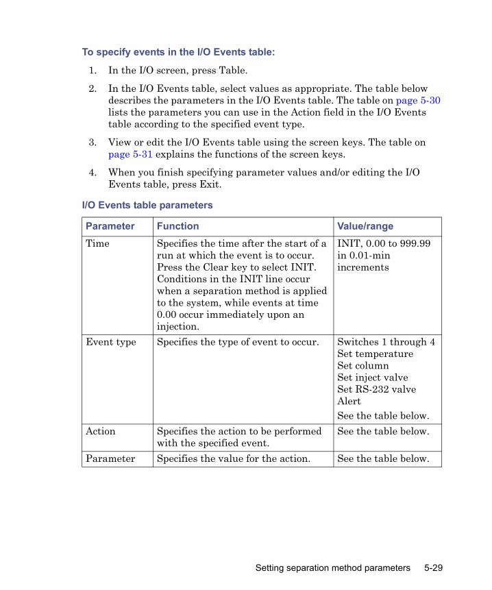
To specify events in the I/O Events table:
1. In the I/O screen, press Table.
2. In the I/O Events table, select values as appropriate. The table below describes the parameters in the I/O Events table. The table on page 5-30 lists the parameters you can use in the Action field in the I/O Events table according to the specified event type.
3. View or edit the I/O Events table using the screen keys. The table on page 5-31 explains the functions of the screen keys.
4. When you finish specifying parameter values and/or editing the I/O Events table, press Exit.
I/O Events table parameters
Parameter Function Value/rangeTime Specifies the time after the start of a
run at which the event is to occur. Press the Clear key to select INIT. Conditions in the INIT line occur when a separation method is applied to the system, while events at time 0.00 occur immediately upon an injection.
INIT, 0.00 to 999.99 in 0.01-min increments
Event type Specifies the type of event to occur. Switches 1 through 4Set temperatureSet columnSet inject valveSet RS-232 valveAlertSee the table below.
Action Specifies the action to be performed with the specified event.
See the table below.
Parameter Specifies the value for the action. See the table below.
Setting separation method parameters 5-29

Action parameters for I/O Events
Event Type Action Value range (param column)Switches 1, 2, 3, or 4(Contact closures, see “I/O signal connections” on page 2-23)
OnOffToggle1
Pulse2
No Change
0.01 to 10.00 in 0.01-min increments (Pulse only)
Set Temperature Sample
Column
4 to 40 °C in 1 °C increments
4 °C (minimum of ambient + 5 °C) to 60 °C in 1 °C increments
Set Column Position 1–6No change
N/A
Set inject valve LoadInjectPrimeNo change
N/A
Set RS-232 valve At address X(where X is the valve address)
Valve position 1 – 6
Alert No action N/A 1. Changes the state of the switch (open to closed, or closed to open).2. A single pulse with a width defined in the param column of the I/O Events table.
5-30 Creating and Editing Separation Methods and Sample Sets

Setting detector parametersIn a standalone mode, System Controller or No Interaction, the separations module can control one Waters 2414, 2410, or 410 Differential Refractometer and as many as two UV/Vis detector channels (Waters 2487 or Waters 486 detectors). Use the IEEE-488 interface bus to connect the separations module to the detector(s). To make I/O connections to these and other detectors, see “I/O signal connections” on page 2-23.Tip: In Ethernet mode, you set up the detector parameters via the chromatography data software (see the detector operator’s guide for specific information).
To enter parameters in the Detectors screen:
1. Press Next or Prev as needed to display the Detectors screen.
2. In the Detectors screen, select the appropriate detector (for example, Absorbance Detector 1), and then press Enter to display the detector selections drop-down list.
Gradient, Detector, and I/O Events table screen keys
Screen key FunctionOverview Displays a time-ordered summary of the events in the
Gradient, Detector, and I/O Events tables.Insert Row Inserts a row above the selected row.Delete Row Deletes the selected row.Sort by Time Sorts the rows based on time.
The separations module’s software automatically sorts entries by time when you exit from the Gradient, Detector, or I/O Events tables.
Copy Down Copies the contents of the current table cell into all subsequent cells in the same column.
Reset Table Clears the table of all current entries.Print Prints the I/O Events, Gradient, or Detector Events
table to a a serial printer, if installed.
Setting separation method parameters 5-31

The following table describes the available detector selections.
3. Set the detector parameter values according to your selected detector(s), as described in the two sections that follow.
Detector selections
Parameter Function SelectionsAbsorbance Detector (1)
Enables a Waters 486/2487 UV/Vis Detector channel
2487, 486, or Not used
Absorbance Detector (2)
Enables a second Waters 486/2487 UV/Vis detector channel
2487, 486, or Not used
Refractive Index Detector
Enables a Waters 2414, 410 or 2410 Differential Refractometer
410/2410 or Not used
Absorbance (1) (screen key)
Displays the 486 or 2487 screen See the table titled “Waters 486 and 2487 UV/Vis parameters” on page 5-33.
Absorbance (2) (screen key)
Displays the second 2487 channel or second 486 screen
See the table titled “Waters 486 and 2487 UV/Vis parameters” on page 5-33.
RI (screen key) Displays the 410/2410 RI screen See the table titled “Waters 410 and 2410 RI Parameters” on page 5-34.
Table (screen key)
Displays the Detector Events table See the table titled “2487 and 486 Detector Events parameters” on page 5-35.
5-32 Creating and Editing Separation Methods and Sample Sets

Setting absorbance detector parameter values
To enter control parameters for a Waters 2487 or 486 UV/Vis detector:
1. In the Detectors screen, press the Abs (1) or Abs (2) screen key to display the appropriate absorbance detector screen. Tip: You cannot select Absorbance Detector (2) unless you already selected an Absorbance Detector (1).
2. Enter detector parameter values, as required.
3. Press OK.Tip: To program detector events, see “Setting the Detector Events table parameter values” on page 5-34.
The following table describes the parameters for the Waters 486 and the 2487 detectors.
Waters 486 and 2487 UV/Vis parameters
Parameter Function Value/rangeλ (wavelength) Specifies the wavelength of the
detector.2487 – 190 to 700 nm in 1-nm increments486 – 190 to 600 nm in 1-nm increments
Sensitivity Specifies the sensitivity of the detector.
2487 – 0.0001 to 4.0000 in 0.0001-AU increments486 – 0.001 to 2.000 in 0.001-AU increments
Filter Specifies the time constant of the filter in the detector.
2487 – 0.1 to 99.0 in 0.1-sec increments486 – 0.1 to 5.0 in 0.1-sec increments
Polarity Specifies the output of the 2487 to create positive or negative peaks.
+, –
Auto zero on inject
Resets the output of the 2487 to 0 volts when the injection begins.
Selected or deselected
Setting separation method parameters 5-33

Setting RI detector parameter values
To enter control parameters for a Waters 410 or 2410 RI detector:
1. In the Detectors screen, press RI to display the 410/2410 detector screen.
2. Enter detector parameter values as required.
3. Press OK.The following table describes the parameters for the Waters 2410 and 410 RI detectors.
Setting the Detector Events table parameter values
The Detector Events table allows you to program 2487 and 486 detector events to occur during a run.
Waters 410 and 2410 RI Parameters
Parameter Function Value/rangeSensitivity Specifies the initial sensitivity of the
detector1, 2, 4, …, 512, 1024
Polarity Specifies the output of the detector to create positive or negative peaks
+, –
Filter Specifies the time constant of the filter in the detector
0.2, 1, 3, and 10 sec
Temperature: Cell
Temperature of the flow cell in °C 30 to 50 °C in 1 °C increments
Temperature: External Temp °C 1
Specifies the temperature of external column heater 1 in °C1
1. The Waters 2410 and 410 Differential Refractometers can control the temperature of one or two external Waters Column Heater Modules (CHM). These devices are separate from the column heater installed with the e2795 Separations Module.
Ambient to 150 °C in 1 °C increments
Temperature: External Temp °C 2
Specifies the temperature of external column heater 2 in °C1
Ambient to 150 °C in 1 °C increments
Autozero on inject
Resets the output of the detector to 0 volts when the injection begins
Selected or deselected
5-34 Creating and Editing Separation Methods and Sample Sets

To enter events in the Detector Events table:
1. In the Detectors screen, press Table.
2. In the Detector Events table, enter or select parameter values as appropriate and press Exit.
The following table describes the parameters in the Detector Events table. The table titled “2487 and 486 Detector actions” on page 5-36 lists the action parameter values you can use according to the specified action parameter.See the table titled “Gradient, Detector, and I/O Events table screen keys” on page 5-31 for information on the Detector Events screen keys.
2487 and 486 Detector Events parameters
Parameter Function Value/rangeTime Indicates the time at which the
action is to occur. Press the Clear key to display INIT. Conditions in the INIT line occur when a separation method is applied to the system, while events at time 0.00 occur immediately upon an injection.
INIT, 0.00 to 999.99 in 0.01-minute increments
Detector Selects the detector on which to perform the action
2487 (1), 2487 (2)486 (1), 486 (2)
Action Selects the action to perform on the selected detector
See the table titled “2487 and 486 Detector actions” on page 5-36
Parameter Defines the action, where appropriate
See the table titled “2487 and 486 Detector actions” on page 5-36
Setting separation method parameters 5-35

The following table describes the actions you can specify with the Waters 2487 and 486 Tunable Absorbance Detectors.
Creating and editing sample sets
A sample set is a set of instructions (displayed in table form) that the separations module uses to perform an automated run in standalone mode. During a run, the separations module performs in sequence the function specified in each row of the sample set table. You create and edit sample sets using the Methods screen.
2487 and 486 Detector actions
Action Function Value rangeSet wavelength
Specifies the wavelength of the detector
2487: 190 to 700 nm in 1-nm increments.486: 190 to 600 nm in 1-nm increments.
Set filter Specifies the time constant of the filter in the detector
2487: 0.1 to 99.0 sec in 0.1-sec increments.486: 0.1 to 5.0 secin 0.1-sec increments.
Set AU full scale
Specifies the absorbance units full scale to adjust the sensitivity of the detector
2487: 0.0001 to 4.0000 AUin 0.0001-AU increments.486: 0.001 to 2.000 AU in 0.001-AU increments.
Set chart mark
Specifies that a chart mark signal be sent to the output terminals
(No values)
Set chart polarity
Specifies the polarity of the analog output
+, –
Auto zero Specifies that an autozero be performed on the detector
(No values)
Set lamp Specifies that the lamp be powered on or off
On, Off
5-36 Creating and Editing Separation Methods and Sample Sets
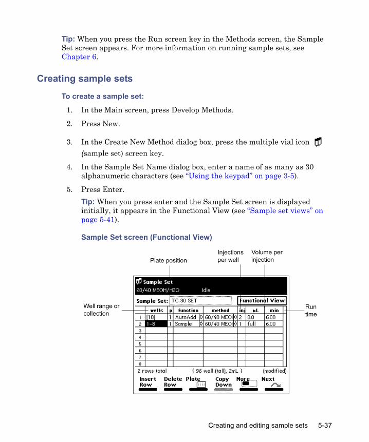
Tip: When you press the Run screen key in the Methods screen, the Sample Set screen appears. For more information on running sample sets, see Chapter 6.
Creating sample sets
To create a sample set:
1. In the Main screen, press Develop Methods.
2. Press New.
3. In the Create New Method dialog box, press the multiple vial icon (sample set) screen key.
4. In the Sample Set Name dialog box, enter a name of as many as 30 alphanumeric characters (see “Using the keypad” on page 3-5).
5. Press Enter.Tip: When you press enter and the Sample Set screen is displayed initially, it appears in the Functional View (see “Sample set views” on page 5-41).
Sample Set screen (Functional View)
Well range or collection
Plate position
Run time
Injections per well
Volume per injection
Creating and editing sample sets 5-37
6. In the Sample Set table, enter parameter values as appropriate (see “Setting sample set parameter values” on page 5-45, and “Setting sample set functions” on page 5-47).
7. Press Exit, and then press Yes to save the sample set. To exit without saving the sample set, press No. To return to the sample set without entering any changes, press Cancel.
Editing sample sets
To edit an existing sample set:
1. In the Main screen, press Develop Methods.
2. Select the sample set and press Edit. Tip: If the sample set is locked, the Edit screen key is unavailable. To unlock the sample set, see “Locking/unlocking sample sets” on page 5-39.
3. Enter sample set table parameter values in the Sample Set screen (see “Setting sample set parameter values” on page 5-45, and “Setting sample set functions” on page 5-47).
4. Press Exit, and then press Yes to save the sample set. To exit without saving the sample set, press No. To return to the sample set without entering any changes, press Cancel.
Copying and editing sample sets
To copy and then edit an existing sample set, leaving the original sample set unchanged:
1. In the Main screen, press Develop Methods.
2. In the Develop Methods screen, select the sample set and press Copy.Tip: To avoid duplicate file names, the separations module automatically appends an extension to the existing file name.
3. Press Enter to accept the default method name, or use the alphabetic screen keys to enter a new name (see “Using the keypad” on page 3-5), then press Enter.
4. Enter new parameter values in the sample set table (see “Setting sample set parameter values” on page 5-45 and “Setting sample set functions” on page 5-47).
5-38 Creating and Editing Separation Methods and Sample Sets
5. Press Exit, and then press Yes to save the sample set. To exit without saving the sample set, press No. To return to the sample set without entering any changes, press Cancel.
Locking/unlocking sample sets
Locking a sample set
Locking a sample set prevents unauthorized changes to a sample set.
To lock a sample set:
1. In the Main screen, press Develop Methods.
2. In the Develop Methods screen, select the sample set and press Lock.
3. Enter a password of as many as 30 alphanumeric characters (see “Using the keypad” on page 3-5), and then press Enter. Result: The sample set is locked and cannot be changed, deleted, or renamed until it is unlocked.Tip: When you copy a locked sample set and save it with a new name, the copy is not locked.
4. Record the password and keep it in a safe place.
Unlocking a sample set
To unlock a sample set:
1. In the Main screen, press Develop Methods.
2. In the Develop Methods screen, select the sample set and press Unlock.
3. Enter the password and press Enter.
Renaming, viewing, and deleting sample sets
Renaming a sample set
To rename a sample set:
1. In the Methods screen, select a sample set to rename.
Creating and editing sample sets 5-39

2. Press More until the Rename screen key appears, and then press Rename.
3. In the Change to Method Name dialog box, enter the new sample set name (see “Using the keypad” on page 3-5).
4. Press Enter.
Viewing a sample set
To view a sample set using the View screen key:
1. In the Methods screen, select a sample set to view.
2. Press More until the View screen key appears, and then press View. Tip: For information on displaying the Functional, Injection, Loading, and Plate Loading views of sample sets, see “Sample set views” on page 5-41.
Deleting sample sets
You can delete a sample set using one of these keys:• Delete screen key• Delete Methods screen key
Restriction: You cannot delete a locked sample set.
To delete a sample set using the Delete screen key:
1. In the Methods screen, select a sample set and press Delete.
2. In the Deleting Method dialog box, press Yes.
To delete a sample set using the Delete Methods screen key:
1. Press More until the Delete Methods screen key appears, and then press Delete Methods.
2. In the Delete Methods dialog box, press Select Method to select the sample set you want to delete.Tip: If you want to select all methods for deletion except the previously selected one(s), press Invert Choices. To clear all selected methods on the Delete Methods screen, press Clear Choices.
5-40 Creating and Editing Separation Methods and Sample Sets

3. Press Delete Now.
Sample set viewsAfter you create or edit a sample set, you can display the sample set in any one of four views:
• Functional view – Displays the sample set with one function per line (see the figure on page 5-37). This view gives you a complete overview of the entire run, including well ranges and any linked rows.Requirement: The Functional View is the only view in which you can make changes to the sample set.
• Injection View – Displays the sample set with one injection per line (See the figure on page 5-42). This list corresponds directly to the chromatograms produced by the run (see the table titled “Sample Set screen keys – Injection View” on page 5-42).
• Loading View – Displays the sample set with one well per line (see the figure on page 5-43). This view shows you how to load samples in the plates (see the table titled “Sample Set screen keys – Loading View” on page 5-43).
• Plate Loading View – Displays the plate graphically within the Loading View. Use the Plates screen key (see the figure on page 5-44) to display the Plate Loading View (see the table titled “Sample Set screen keys – Plate Loading view” on page 5-44).
The following table describes the functions of the screen keys in the Sample Set screen Functional View.
Sample Set screen keys – Functional View
Screen key FunctionInsert Row Inserts a row between the selected row and the row above.Delete Row Deletes the selected row.Plates Graphically displays the Well Selector and selected wells.Copy Down Copies the value in the currently selected cell to the
corresponding cell in all subsequent rows.
Creating and editing sample sets 5-41

Sample Set Screen – Injection View
The following table describes the functions of the screen keys displayed in the Injection View.
Make Link/Break Link
Attaches/detaches the currently selected row to/from its predecessor. Linked rows provide a tool for repeating a series of functions using the well range or collection as a counter. See “Linking rows in a sample set” on page 5-56.
Reset Table Clears all entries in the sample set table.Row Details Displays and allows entry of additional parameters for the
selected function.Print Prints the contents of the current screen to a serial
printer, if connected.Next/Previous Opens the next view or returns to the previous view.
Sample Set screen keys – Injection View
Screen key FunctionPrint Prints the contents of the current screen to a serial
printer, if connected.Next/Previous Opens the next view or returns to the previous view.
Sample Set screen keys – Functional View (Continued)
Screen key Function
Numerical well numbers
5-42 Creating and Editing Separation Methods and Sample Sets
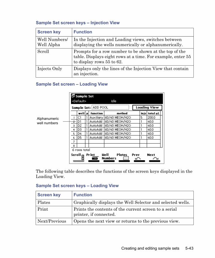
Sample Set screen – Loading View
The following table describes the functions of the screen keys displayed in the Loading View.
Well Numbers/Well Alpha
In the Injection and Loading views, switches between displaying the wells numerically or alphanumerically.
Scroll Prompts for a row number to be shown at the top of the table. Displays eight rows at a time. For example, enter 55 to display rows 55 to 62.
Injects Only Displays only the lines of the Injection View that contain an injection.
Sample Set screen keys – Loading View
Screen key FunctionPlates Graphically displays the Well Selector and selected wells.Print Prints the contents of the current screen to a serial
printer, if connected.Next/Previous Opens the next view or returns to the previous view.
Sample Set screen keys – Injection View
Screen key Function
Alphanumericwell numbers
Creating and editing sample sets 5-43

Plate Loading View
The following table describes the functions of the screen keys displayed in the Plate Loading View.
Well Numbers/Well Alpha
In the Injection and Loading views, switches between displaying the wells numerically or alphanumerically.
Scroll Prompts for a row number to be shown at the top of the table. Displays eight rows at a time. For example, enter 55 to display rows 55 to 62.
Sample Set screen keys – Plate Loading view
Screen key FunctionPrint Prints the contents of the current screen to a serial
printer, if connected.1 Blue2 Yellow3 Red4 Green
In the Plate Loading view, one button is displayed for each plate used in the sample set. The button corresponding to the current plate is unavailable (see “Loading the sample plates” on page 3-38).
Sample Set screen keys – Loading View
Screen key Function
5-44 Creating and Editing Separation Methods and Sample Sets

Setting sample set parameter valuesThe following table provides parameters, functions, and values you use to set up the sample set table in the Functional View.
Sample set parameters – Functional View
Parameter Function Value rangeWells Specifies the well numbers from which the
injection is to be made. Use the “.” key to specify a well number range. For example, press 2.5 to enter wells 2 through 5.Use the Plates screen key to display the plate graphically. In the Well Selector, you can select a collection of wells that are noncontiguous. For more information, see “Selecting wells for making injections” on page 4-21.
1 to 384 (depending on plate type).Use the Plates screen key to specify plate type.
p (plate position)
Specifies the plate position in the carrier (see “Loading the sample plates” on page 3-38).
1 to 4
Function Specifies the action/process to perform for the row in the Sample Set table (see “Setting sample set functions” on page 5-47).
See the table titled “Sample set functions” on page 5-47
Method Specifies the separation method to use with the specified function in the sample set (see “Creating and editing separation methods” on page 5-3, for the procedures to create, edit, and store separation methods).
Stored methods
Inj (injections per well)
Specifies the number of injections to perform from each well in the range or collection.
1 to 99
Creating and editing sample sets 5-45
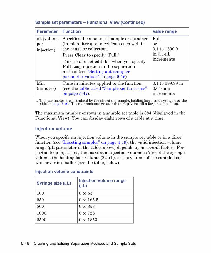
The maximum number of rows in a sample set table is 384 (displayed in the Functional View). You can display eight rows of a table at a time.
Injection volume
When you specify an injection volume in the sample set table or in a direct function (see “Injecting samples” on page 4-19), the valid injection volume range (μL parameter in the table, above) depends upon several factors. For partial loop injections, the maximum injection volume is 75% of the syringe volume, the holding loop volume (22 μL), or the volume of the sample loop, whichever is smaller (see the table, below).
µL (volume per injection)1
Specifies the amount of sample or standard (in microliters) to inject from each well in the range or collection.Press Clear to specify “Full.”This field is not editable when you specify Full Loop injection in the separation method (see “Setting autosampler parameter values” on page 5-16).
Fullor0.1 to 1500.0in 0.1-µL increments
Min (minutes)
Time in minutes applied to the function (see the table titled “Sample set functions” on page 5-47).
0.1 to 999.99 in 0.01-min increments
1. This parameter is constrained by the size of the sample, holding loops, and syringe (see the table on page 7-40). To enter amounts greater than 50 μL, install a larger sample loop.
Injection volume constraints
Syringe size (μL) Injection volume range (μL)
100 0 to 53250 0 to 165.5500 0 to 3531000 0 to 7282500 0 to 1853
Sample set parameters – Functional View (Continued)
Parameter Function Value range
5-46 Creating and Editing Separation Methods and Sample Sets
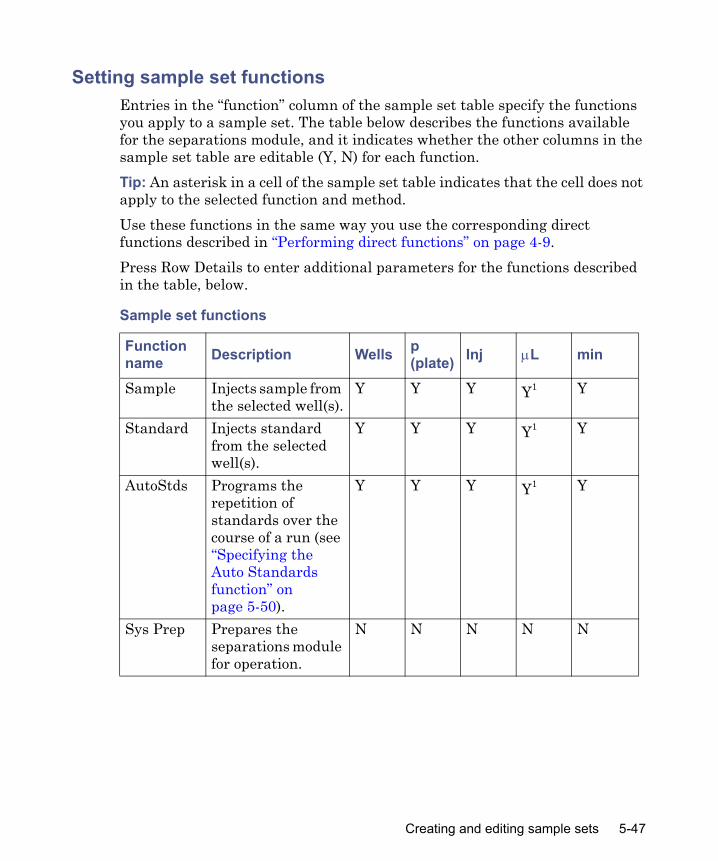
Setting sample set functionsEntries in the “function” column of the sample set table specify the functions you apply to a sample set. The table below describes the functions available for the separations module, and it indicates whether the other columns in the sample set table are editable (Y, N) for each function.Tip: An asterisk in a cell of the sample set table indicates that the cell does not apply to the selected function and method.Use these functions in the same way you use the corresponding direct functions described in “Performing direct functions” on page 4-9.Press Row Details to enter additional parameters for the functions described in the table, below.
Sample set functions
Function name Description Wells p
(plate) Inj μL min
Sample Injects sample from the selected well(s).
Y Y Y Y1 Y
Standard Injects standard from the selected well(s).
Y Y Y Y1 Y
AutoStds Programs the repetition of standards over the course of a run (see “Specifying the Auto Standards function” on page 5-50).
Y Y Y Y1 Y
Sys Prep Prepares the separations module for operation.
N N N N N
Creating and editing sample sets 5-47

Condition Delivers to the column the gradient specified in the separation method; conditions the column without injecting samples (see “Conditioning the column” on page 4-18).
N N N N Enter column conditioning time.2
Prime Wet primes the solvent management system at the specified rate for the specified period (see “Wet priming the system” on page 4-15).
N N N N Enter a duration for the Prime function.
Refresh Syringe
Refreshes the solvent in the syringe (see “Refreshing the syringe” on page 3-36).
N N N N N
Wash Needle
Washes the needle and purges the sample management system (see “Washing the needle and injection port” on page 4-17).
N N N N N
Sample set functions (Continued)
Function name Description Wells p
(plate) Inj μL min
5-48 Creating and Editing Separation Methods and Sample Sets

Equil (Equilibrate)
Delivers solvent through the system for the specified period of time using the initial conditions in the specified separation method (see “Specifying the Equilibrate function” on page 5-51).
N N N N Enter system equilibration time.
Auto Add Collects sample from a single well and non-sample material from other wells into the sample loop for injection in a specified order (see “Specifying the Auto Add function” on page 5-52).
Y Y Y Y3 Y
Pool Collects multiple samples into the sample loop for injection all at once (see “Specifying the Pool function” on page 5-54).
N N Y N4 Y
1. Not editable (N) when the separation method is for full loop injection only.2. Specify sufficient time to deliver the specified gradient to the column.3. Never “Full.”4. Injection volume is not editable in the sample set table for the Pool function. Volume
injected is the total of all volumes entered individually in the Pool Row Details and sample gaps, if any.
Sample set functions (Continued)
Function name Description Wells p
(plate) Inj μL min
Creating and editing sample sets 5-49

Specifying the Auto Standards function
Use the AutoStds function in the sample set table to run standards repetitively (at specified intervals) throughout the run. You can use as many as three standard wells for large runs.
To specify the Auto Standards function:
1. In the Sample Set screen, select AutoStds from the list of functions, and then press Row Details to open the Auto Standards dialog box.
Auto Standards dialog box
2. In the “Run standards every boxes”, enter the frequency with which to run standards (after how many wells or injections), and then select either wells or injects from the list.
3. You can select standards wells via one of the following methods:• In the Source Well(s) table, enter the location of each standards well
in the well column and its “practical capacity” (that is, the amount that can be removed from the standards well based on the well depth) in the total μL column.
• Press the Plate screen key to graphically select a standards well.
4. Press OK after you have completed your selection (or press Cancel to exit without making a selection). For more information, see “Selecting wells for making injections” on page 4-21.
5-50 Creating and Editing Separation Methods and Sample Sets
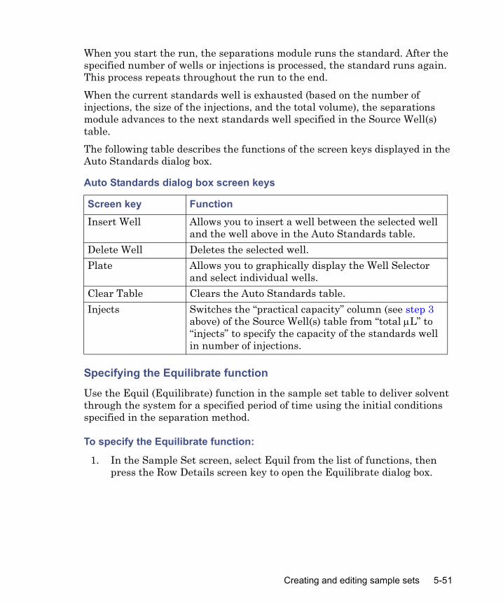
When you start the run, the separations module runs the standard. After the specified number of wells or injections is processed, the standard runs again. This process repeats throughout the run to the end.When the current standards well is exhausted (based on the number of injections, the size of the injections, and the total volume), the separations module advances to the next standards well specified in the Source Well(s) table.The following table describes the functions of the screen keys displayed in the Auto Standards dialog box.
Specifying the Equilibrate function
Use the Equil (Equilibrate) function in the sample set table to deliver solvent through the system for a specified period of time using the initial conditions specified in the separation method.
To specify the Equilibrate function:
1. In the Sample Set screen, select Equil from the list of functions, then press the Row Details screen key to open the Equilibrate dialog box.
Auto Standards dialog box screen keys
Screen key FunctionInsert Well Allows you to insert a well between the selected well
and the well above in the Auto Standards table.Delete Well Deletes the selected well.Plate Allows you to graphically display the Well Selector
and select individual wells.Clear Table Clears the Auto Standards table.Injects Switches the “practical capacity” column (see step 3
above) of the Source Well(s) table from “total μL” to “injects” to specify the capacity of the standards well in number of injections.
Creating and editing sample sets 5-51

Equilibrate dialog box
2. In the Column box (if a column selection valve is installed), select the appropriate column selection option from the list, and then press Enter.Tip: You cannot access the Column box if there is no column selection valve installed.
3. In the Time box, enter the time, in minutes required to equilibrate the column.
4. For the typical unattended operation, leave the “Hold when time expires” check box cleared. If you enable the check box and set a time, the separations module maintains (holds) initial conditions until the set time expires and requires a response when you press either of the two Status screen keys (Resume Sample or Abort Samples), which performs the described action. Elapsed time continues until you press one of the keys. For more information, see “Equilibrating the system” on page 4-18.
Specifying the Auto Add function
Use the Auto Add function to make an injection that is composed of a single sample aliquot along with as many as 16 aliquots from additional wells that can contain diluents, reagents, catalysts, or other non-sample material. You can specify a delay time to allow the aliquots in the sample loop to mix before an injection.Recommendation: Specify the total volume of an Auto Add injection to be less than half the volume of the sample loop.
5-52 Creating and Editing Separation Methods and Sample Sets

To specify the Auto Add function:
1. In the Sample Set screen, select AutoAdd from the list of functions, then press the Row Details screen key to open the Auto Add dialog box.Requirement: Only one line of the Auto Add table can be a SAMPLE line, a placeholder for the actual well location used according to the range or collection entered in the Wells column of the sample set’s Functional View.
Auto Add dialog box
2. Enter the volume (in µL) you want to draw from the SAMPLE well.
3. Repeat step 1 and step 2 for additional aliquots. Tip: You can insert aliquots before the SAMPLE line.
4. Enter the delay time, in minutes, to allow the combined aliquots to commingle in the sample loop.
5. Press OK.
Creating and editing sample sets 5-53

The following table describes the functions of the screen keys displayed in the Auto Add dialog box.
Specifying the Pool function
Use the Pool function to make a single injection composed of multiple samples from as many as 16 wells in series.Tip: The pooling function is available when the separations module is in the No Interaction mode. Pooling is not supported for MassLynx control.Recommendation: Specify the total volume of a Pool injection to be less than half the sample loop volume.
To specify the Pool function:
1. In the sample set table, select or insert a row in the sample set to specify sample pooling.
2. In the function field of the selected row, select Pool from the list.
3. Press More and then Row Details to open the Pool Samples dialog box.
Auto Add dialog box screen keys
Screen key FunctionPlate Graphically displays the Well Selector, allowing
selection of individual wells.Insert Well Insert a well between the selected well and the well
above in the Auto Add table.Delete Well Deletes the selected well.Clear Table Clears all entries in the Auto Add table.
5-54 Creating and Editing Separation Methods and Sample Sets
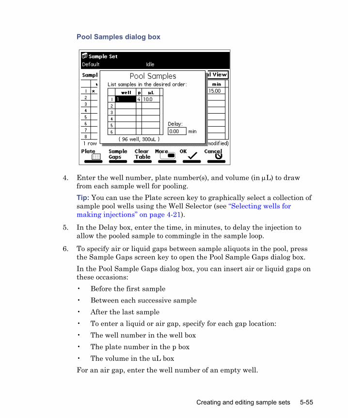
Pool Samples dialog box
4. Enter the well number, plate number(s), and volume (in μL) to draw from each sample well for pooling.Tip: You can use the Plate screen key to graphically select a collection of sample pool wells using the Well Selector (see “Selecting wells for making injections” on page 4-21).
5. In the Delay box, enter the time, in minutes, to delay the injection to allow the pooled sample to commingle in the sample loop.
6. To specify air or liquid gaps between sample aliquots in the pool, press the Sample Gaps screen key to open the Pool Sample Gaps dialog box.In the Pool Sample Gaps dialog box, you can insert air or liquid gaps on these occasions:• Before the first sample• Between each successive sample• After the last sample• To enter a liquid or air gap, specify for each gap location:• The well number in the well box• The plate number in the p box• The volume in the uL boxFor an air gap, enter the well number of an empty well.
Creating and editing sample sets 5-55

Pool Sample Gaps dialog box
Tip: You need to enter a volume for the Pool Sample Gaps function to operate correctly.You can specify that each sample gap be selected from a different well or plate. All are defaulted to well collection “[0]” meaning that no sample gaps are specified. To change a well box with an entry in it to “[0],” press Clear.
7. When you complete the Pool Sample Gaps dialog box, press OK (or press Cancel to exit the dialog box without entering any information).
8. When you complete the Pool Samples table, press OK (or press Cancel to exit the Pool Samples dialog box without entering any information in the table).
Linking rows in a sample setYou can link two or more rows in a sample set to perform multiple functions for the same set of wells. For example, you can link a Sample function with the Equilibrate and Refresh Syringe functions, as shown in Rows 2, 3, and 4, below. In this example, one 10-µL injection is made after equilibrating for 2.0 minutes, followed by the Refresh Syringe function. The process is repeated for all 16 wells in the collection.Tip: When unlinking or deleting linked rows in a sample set, be aware that well numbers in the remaining rows can differ from those originally entered.
5-56 Creating and Editing Separation Methods and Sample Sets
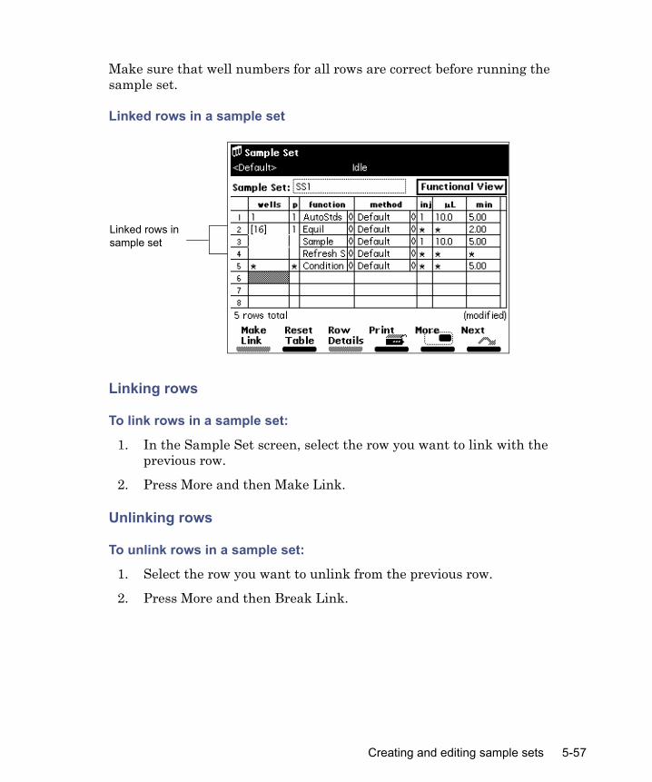
Make sure that well numbers for all rows are correct before running the sample set.
Linked rows in a sample set
Linking rows
To link rows in a sample set:
1. In the Sample Set screen, select the row you want to link with the previous row.
2. Press More and then Make Link.
Unlinking rows
To unlink rows in a sample set:
1. Select the row you want to unlink from the previous row.
2. Press More and then Break Link.
Linked rows in sample set
Creating and editing sample sets 5-57

5-58 Creating and Editing Separation Methods and Sample Sets

6 Performing Automatic Runs and High-Throughput Operation
Contents
Topic PageSetting up for automatic runs 6-2Making automatic runs in a standalone mode 6-3Setting up for high-throughput operation 6-9
6-1

Setting up for automatic runs
You can set up the separations module to make automatic runs when it operates as follows:
• In System Controller or No Interaction mode• Controlled by Empower or Millennium software• Controlled by MassLynx software
See “Operating configurations” on page 1-16 for details about separations module control modes.
System Controller or No Interaction modeIf your HPLC system uses the separations module in the System Controller or No Interaction mode, you perform an automatic run using a sample set or sample template stored in the separations module. Chapter 5 explains how to create and store separation methods, sample sets, and sample templates. You run existing sample sets and sample templates from the separations module’s Main screen (see “Making automatic runs in a standalone mode” on page 6-3).
Controlled by Empower or Millennium softwareIf your HPLC system is controlled by Empower or Millennium software (see “Configuring the operating mode” on page 3-25), you perform an automatic run using a project, instrument method, configured system, method set, and sample set stored in software. For details on performing runs using Empower or Millennium software, see the Empower or Millennium online help.
Considerations when performing runs controlled by Empower or Millennium software
• When the separations module is controlled by Empower or Millennium software, the word “Remote” appears in the separations module front panel banner area.
• When you start an automatic run, any running sample set or method programmed locally at the separations module automatically terminates.
6-2 Performing Automatic Runs and High-Throughput Operation

• When the separations module is running under Empower or Millennium software control, and you press Abort in the Run Samples window, the separation module continues running the current gradient and event functions.
• You can operate the separations module from its front panel whenever it is not being run by the Empower or Millennium software (see “No Interaction mode” on page 3-26).
Controlled by MassLynx softwareIf your HPLC or LC/MS system is controlled by MassLynx software (see “Configuring the operating mode” on page 3-25), you make automatic runs using the MassLynx sample processing list. The list contains the method(s) that defines the separations module’s operating parameters and those of the system’s detector (but not the mass spectrometer, if included). For details on performing a run using MassLynx software, see the MassLynx online help.
Considerations when performing runs controlled by MassLynx software
• When the separations module is controlled by MassLynx software, the word “Remote” appears in the separations module front panel banner area.
• When MassLynx software is not running, you can operate the separations module from its front panel (see “No Interaction mode” on page 3-26).
Making automatic runs in a standalone mode
The following figure summarizes the steps for making an automatic run in a standalone mode (System Controller or No Interaction).
Caution: Do not edit the default method in the separations module when the separations module is running under Empower or Millennium software control. Doing so can cause unexpected behavior.
Making automatic runs in a standalone mode 6-3

Making an automatic run in a standalone mode
Running a sample setTip: See Chapter 5 for information on creating, storing, and importing separation methods and sample sets.
To run a sample set in a standalone mode:
1. In the Main screen, press Run Samples.Result: The Run Samples screen appears, listing the available separation methods and sample sets.
Select the separation method or sample set to run.
Press Run Samples in the Main screen.
Enter the appropriate information to complete the sample set operating conditions
Press Run to proceed, or press Initial Conditions to start the solvent management system.
The run ends as programmed.
Press the Routine screen key to begin the run.
6-4 Performing Automatic Runs and High-Throughput Operation

Run Samples screen (example)
2. In the Run Samples screen, select a sample set, and then press one of the following screen keys:• Initial Conds – Starts the solvent management system at the initial
conditions specified in the first line of the sample set and begins equilibrating the temperature in the sample heater/cooler and column heater or column heater/cooler. When the system is equilibrated, press the Run screen key.
• Run – Displays the selected sample set table (to view or edit). Use the screen keys to modify the table.
07/28/08
Making automatic runs in a standalone mode 6-5
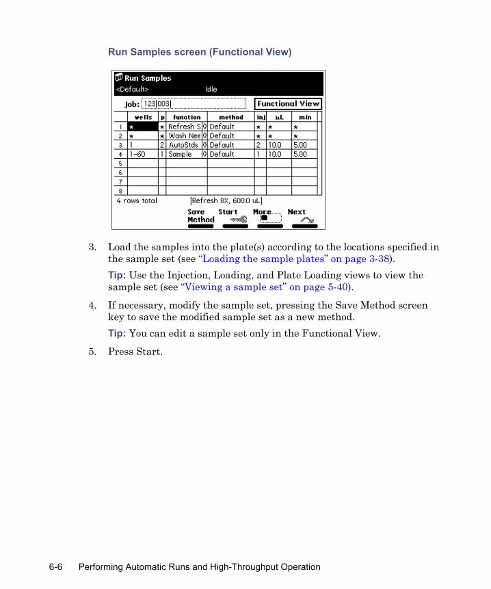
Run Samples screen (Functional View)
3. Load the samples into the plate(s) according to the locations specified in the sample set (see “Loading the sample plates” on page 3-38).Tip: Use the Injection, Loading, and Plate Loading views to view the sample set (see “Viewing a sample set” on page 5-40).
4. If necessary, modify the sample set, pressing the Save Method screen key to save the modified sample set as a new method.Tip: You can edit a sample set only in the Functional View.
5. Press Start.
6-6 Performing Automatic Runs and High-Throughput Operation

Run Samples Requirements screen (example)
6. In the Run Samples Requirements screen, verify all information is correct.Tip: If a printer is connected to your system, press Print to print the contents of the Requirements screen and a listing of the injections.
7. Press Routine to start a normal run, or press STAT to make a stat run (see “Performing a stat run”, below).
Modifying a sample set during a runIn a standalone mode, you can modify operating conditions during a run by performing a stat run or editing the separation method.
Performing a stat run
Use the stat run function to interrupt a run in progress, perform one or more injections after the current injection is completed, and then continue with the scheduled run. Performing a stat run is most useful when the separation methods for the stat run and the scheduled run use identical solvents and temperatures.Restriction: If the separations module’s sample management system is drawing or loading a sample when you start a stat run, the plate carrier cannot move, and a warning message is displayed if a plate position change is specified. Wait for the sample injection to finish before continuing.
Making automatic runs in a standalone mode 6-7

To perform a stat run while a sample set is running:
1. Load the stat run samples into the sample plate, and then place the plate in the sample compartment, and close the sample compartment door.
2. In the Main screen, press Run Samples.
3. In the Run Samples screen, select the separation method or sample set to use for the stat run and press Run.
4. Enter the well position(s) and other parameters in the appropriate boxes and press Start.
5. In the Run Samples Requirements screen, verify all information is correct and press STAT.Result: After the Stat run ends, the original run resumes immediately.
Modifying a separation method during a run
You can modify a separation method while a sample set is running. Requirements:
• If the separation method you are modifying is being used for the current injection, the current injection is unaffected by the changes.
• You must save the changes to the separation method before you can apply the modified separation method to any subsequent injections. Use the procedures in “Editing separation methods” on page 5-4, to modify and save the separation method.
Stopping a runTo stop a run in progress, press one of the following keys in the Status screen:
• Stop (Function) (screen key) – Stops the current function and changes the Status screen keys to Abort and Resume (see below).
• Hold (Function) (screen key) – Allows the current function to finish, suspends operation of subsequent functions, and displays screen keys that allow you to abort or resume the sample set.
6-8 Performing Automatic Runs and High-Throughput Operation

• Hold Gradient (screen key) – Maintains the current gradient conditions. A screen key allows you to resume the gradient.
• Stop Flow (keypad) – Stops the flow of solvent, suspends operation of the current function, and displays screen keys that allow you to abort or resume the function.
If any alarm condition specified in the separation method or sample set is set to “Stop Function” or “Stop Flow” and the alarm condition occurs, a dialog box appears indicating the alarm condition, and the following screen keys appear:
• Abort – Cancels the current function• Resume – Resumes the current function
Setting up for high-throughput operation
When you use gradient separations, you can reduce cycle time and, therefore, significantly increase sample throughput by taking advantage of the separations module’s parallel processing capabilities. These capabilities allow the separations module to prepare the next sample for injection before the current sample cycle is complete.The separations module provides the following three ways to perform LC applications:
• Sequential (traditional) chromatography (see the figure “Sequential processing cycle for gradient chromatography” on page 6-11) – All operations are performed in sequence (one after the other).
• Parallel processing – Some operations are performed concurrently (see the figure “Parallel processing cycle for gradient chromatography” on page 6-13).
• Parallel processing with rapid equilibration – Some operations are performed concurrently, and the column is taken off-line while the system is equilibrated at a high flow rate (see the figure “Parallel processing with rapid equilibration cycle for gradient chromatography” on page 6-15).In addition, if you specify a pre-column volume when using any one of the three processing methods, the solvent management system delivers the gradient to the injection valve in parallel with column equilibration for “just-in-time” gradient delivery.
Setting up for high-throughput operation 6-9

The figure “Comparison of cycle times” on page 6-18 shows a comparison of chromatograms produced using sequential, parallel, and parallel with rapid equilibration processing methods.Recommendation: Do not calibrate or perform a quantitative analysis of your system based on the first in a series of parallel injections. The first injection can differ in its timing because it is not coordinated with a previous injection. Results obtained from the first injection can vary from those of subsequent injections.As you develop separation methods for high-throughput applications (see “Creating and editing separation methods” on page 5-3 and “Setting separation method parameters” on page 5-7), you can possibly need to change certain parameter values from those values used in sequential processing. For parallel processing methods, you can possibly need to change the following Autosampler Page parameters:
• Injection mode• Loop offline time• Loop option (full or partial)• Full loop overfill• Pre-column volume• Aspirate air, pre- and post-sample
For parallel processing with rapid equilibration methods, you can possibly need to change the above Autosampler Page parameters and the following Rapid Equilibration dialog box parameters:
• Path• Flow• Duration• Column reequilibration
Sequential processingIn sequential processing (traditional chromatography), most LC system operations occur in series. However, in all three processing modes, the needle-wash and purge cycles occur in parallel with the gradient separation.
6-10 Performing Automatic Runs and High-Throughput Operation

Sequential processing cycle for gradient chromatography
Sequential processing example
The following figure shows the Autosampler screen parameters for the sequential processing in this example.
Autosampler screen parameter values for sequential processing separation method (example)
Run gradient
End run
Start run
Equilibrate system
Equilibrate columnWash needle
(includes purge)
Stop cycle
Load sample loop
Draw sample (into holding loop)
Inject sample
Gradient moves to column
Start cycle
Setting up for high-throughput operation 6-11
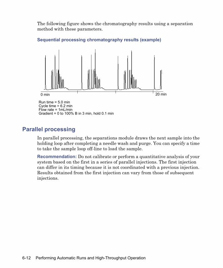
The following figure shows the chromatography results using a separation method with these parameters.
Sequential processing chromatography results (example)
Parallel processingIn parallel processing, the separations module draws the next sample into the holding loop after completing a needle wash and purge. You can specify a time to take the sample loop off-line to load the sample.Recommendation: Do not calibrate or perform a quantitative analysis of your system based on the first in a series of parallel injections. The first injection can differ in its timing because it is not coordinated with a previous injection. Results obtained from the first injection can vary from those of subsequent injections.
Run time = 5.0 min
0 min 20 min
Cycle time = 6.2 minFlow rate = 1mL/minGradient = 0 to 100% B in 3 min, hold 0.1 min
6-12 Performing Automatic Runs and High-Throughput Operation

Parallel processing cycle for gradient chromatography
Tip: You can also specify a pre-column volume to achieve “just-in-time” delivery of the gradient by the solvent management system (see “Parallel processing with rapid equilibration” on page 6-15 for an example).
Parallel processing exampleThe following figure shows the Autosampler screen’s parameter values for specifying parallel processing.Tip: To minimize sample diffusion with parallel sample processing, incorporate air gaps (3 to 5 μL), pre- and post-sample.
Run gradient
End runStart run
Equilibrate system
Equilibrate column
Wash needle (includes purge)
Stop cycle
Inject sample loaded previously
Gradient moves to column
Start cycle
Draw next sample (into holding loop)
Load sample loop
Setting up for high-throughput operation 6-13

Autosampler screen parameter values for parallel processing separation method (example)
The following figure shows the chromatography resulting from using a separation method that adopts the parameter values in the figure above.
Parallel processing chromatography results (example)
The parallel processing example demonstrates the reduction in cycle time compared to the sequential method (as shown in the figure “Sequential processing chromatography results (example)” on page 6-12).
400.0
0 min 20 min
Run time = 5.0 minCycle time = 5.1 minFlow rate = 1mL/minGradient = 0 to 100% B in 3 min, hold 0.1 min
6-14 Performing Automatic Runs and High-Throughput Operation
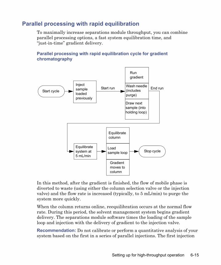
Parallel processing with rapid equilibrationTo maximally increase separations module throughput, you can combine parallel processing options, a fast system equilibration time, and “just-in-time” gradient delivery.
Parallel processing with rapid equilibration cycle for gradient chromatography
In this method, after the gradient is finished, the flow of mobile phase is diverted to waste (using either the column selection valve or the injection valve) and the flow rate is increased (typically, to 5 mL/min) to purge the system more quickly.When the column returns online, reequilibration occurs at the normal flow rate. During this period, the solvent management system begins gradient delivery. The separations module software times the loading of the sample loop and injection with the delivery of gradient to the injection valve.Recommendation: Do not calibrate or perform a quantitative analysis of your system based on the first in a series of parallel injections. The first injection
Run gradient
End runStart run
Equilibrate system at 5 mL/min
Equilibrate column
Wash needle (includes purge)
Stop cycle
Inject sample loaded previously
Gradient moves to column
Start cycle
Draw next sample (into holding loop)
Load sample loop
Setting up for high-throughput operation 6-15

can differ in its timing because it is not coordinated with a previous injection. Results obtained from the first injection can vary from those of subsequent injections.
Parallel processing with rapid equilibration example
The following two figures show the Autosampler screen and Rapid Equilibration dialog box parameter values, which specify parallel processing with rapid equilibration. The figure on page 6-17 shows the chromatography that results when you use a separation method with those parameter values.Tip: If you specify rapid equilibration parameters in the Autosampler screen, the software ignores the Loop off-line parameter.
Autosampler screen parameter values for parallel processing with rapid equilibration separation method (example)
See “Determining the pre-column volume for parallel processing” on page 6-18 and “Specifying rapid equilibration values” on page 6-19 for information about determining pre-column volume and column reequilibration values for your application.
6-16 Performing Automatic Runs and High-Throughput Operation

Rapid equilibration dialog box parameter values (example)
Parallel processing with rapid equilibration chromatography results (example)
Comparing cycle times
The following figure shows a comparison of chromatograms from the three processing methods and their cycle times.
0 min 20 min
Run time = 3.2 minCycle time = 4.4 minFlow rate = 1mL/minGradient = 0 to 100% B in 3 min, hold 0.1 min
Setting up for high-throughput operation 6-17

Comparison of cycle times
Determining the pre-column volume for parallel processing
Use this section to determine the pre-column volume to specify when you use an Alliance HT system for high-throughput gradient chromatography.Tip: The pre-column volume measurement is approximate. Actual pre-column volume values vary depending on your application.Recommended materials
• UV detector, λ 254• Restrictor capable of > 300 psi at 1 mL/min placed where the column
connects to the injection valve (or use a short column placed after the detector to produce backpressure)
• Mobile phase A, methanol; B, 1% acetone in methanol
A
A = Parallel with Rapid Equilibration, Cycle Time = 4.4 min.B = Parallel, Cycle Time = 5.1 min.C = Sequential, Cycle Time = 6.2 min.
B
C
6-18 Performing Automatic Runs and High-Throughput Operation
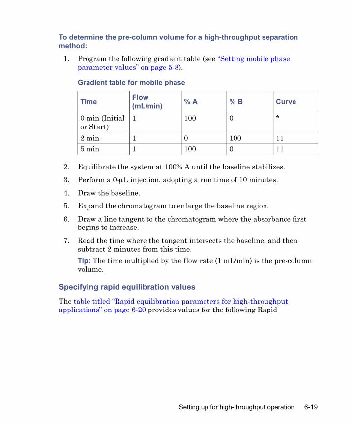
To determine the pre-column volume for a high-throughput separation method:
1. Program the following gradient table (see “Setting mobile phase parameter values” on page 5-8).
2. Equilibrate the system at 100% A until the baseline stabilizes.
3. Perform a 0-μL injection, adopting a run time of 10 minutes.
4. Draw the baseline.
5. Expand the chromatogram to enlarge the baseline region.
6. Draw a line tangent to the chromatogram where the absorbance first begins to increase.
7. Read the time where the tangent intersects the baseline, and then subtract 2 minutes from this time. Tip: The time multiplied by the flow rate (1 mL/min) is the pre-column volume.
Specifying rapid equilibration values
The table titled “Rapid equilibration parameters for high-throughput applications” on page 6-20 provides values for the following Rapid
Gradient table for mobile phase
Time Flow (mL/min) % A % B Curve
0 min (Initial or Start)
1 100 0 *
2 min 1 0 100 115 min 1 100 0 11
Setting up for high-throughput operation 6-19
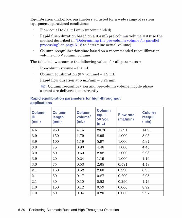
Equilibration dialog box parameters adjusted for a wide range of system equipment operational conditions:
• Flow equal to 5.0 mL/min (recommended)• Rapid flush duration based on a 0.4 mL pre-column volume × 3 (use the
method described in “Determining the pre-column volume for parallel processing” on page 6-18 to determine actual volume)
• Column reequilibration time based on a recommended reequilibration volume of 5 × column volume
The table below assumes the following values for all parameters:• Pre-column volume – 0.4 mL• Column equilibration (3 × volume) – 1.2 mL• Rapid flow duration at 5 mL/min – 0.24 min
Tip: Column reequilibration and pre-column volume mobile phase solvent are delivered concurrently.
Rapid equilibration parameters for high-throughputapplications
Column ID(mm)
Columnlength(mm)
Columnvolume1
(mL)
Column equil. 5× Vol. (mL)
Flow rate(mL/min)
Columnreequil.(min)
4.6 250 4.15 20.76 1.391 14.933.9 150 1.79 8.95 1.000 8.953.9 100 1.19 5.97 1.000 5.973.9 75 0.90 4.48 1.000 4.483.9 50 0.60 2.98 1.000 2.983.9 20 0.24 1.19 1.000 1.193.0 75 0.53 2.65 0.591 4.482.1 150 0.52 2.60 0.290 8.952.1 50 0.17 0.87 0.290 2.982.1 30 0.10 0.52 0.290 1.791.0 150 0.12 0.59 0.066 8.921.0 50 0.04 0.20 0.066 2.97
6-20 Performing Automatic Runs and High-Throughput Operation
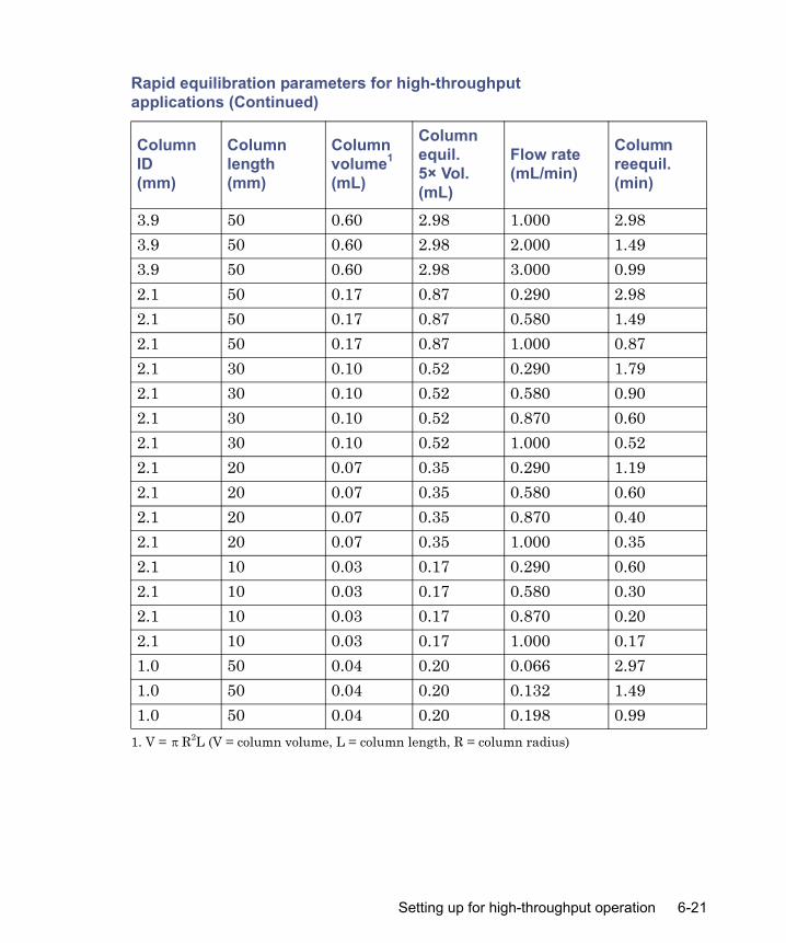
3.9 50 0.60 2.98 1.000 2.983.9 50 0.60 2.98 2.000 1.493.9 50 0.60 2.98 3.000 0.992.1 50 0.17 0.87 0.290 2.982.1 50 0.17 0.87 0.580 1.492.1 50 0.17 0.87 1.000 0.872.1 30 0.10 0.52 0.290 1.792.1 30 0.10 0.52 0.580 0.902.1 30 0.10 0.52 0.870 0.602.1 30 0.10 0.52 1.000 0.522.1 20 0.07 0.35 0.290 1.192.1 20 0.07 0.35 0.580 0.602.1 20 0.07 0.35 0.870 0.402.1 20 0.07 0.35 1.000 0.352.1 10 0.03 0.17 0.290 0.602.1 10 0.03 0.17 0.580 0.302.1 10 0.03 0.17 0.870 0.202.1 10 0.03 0.17 1.000 0.171.0 50 0.04 0.20 0.066 2.971.0 50 0.04 0.20 0.132 1.491.0 50 0.04 0.20 0.198 0.99
1. V = R2L (V = column volume, L = column length, R = column radius)
Rapid equilibration parameters for high-throughputapplications (Continued)
Column ID(mm)
Columnlength(mm)
Columnvolume1
(mL)
Column equil. 5× Vol. (mL)
Flow rate(mL/min)
Columnreequil.(min)
π
Setting up for high-throughput operation 6-21

Separation methods templatesYou can use the separations module’s four templates as a guide for developing customized separations methods. The names of the separations methods are listed below. You can adopt the templates unedited, or you can edit them as necessary using the “Save as” function to rename them to a unique identifier.These are the separations module’s four templates:
• SequentialNCE:template• SequentialCE:template• SequentialPCE:template• RapidEquilCE:template
These templates provide starting points for medium to high-throughput, generic gradient methods, and then incorporate different software capabilities of the separations module that decrease analysis cycle time. Parameters not listed in the table titled “Template parameters” on page 6-23 reflect no change from default method parameters. The templates have a common set of assumptions:
• Column: Reverse phase, 2.1 × 50 mm, 3.5 μm particles, 0.17-mL internal volume
• Binary Generic Gradient: 0-100%B in 3 min, return to 0%B at 3.1 min• System pre-column volume: 350 μL.• Reequilibration volumes: 3 times pre-column volume and 5 times
column volume• Column selector: none installed
The rate of solvent change of the generic gradient in the template is relatively gradual and serves as a starting point only. Cycle times can be greatly reduced by use of a steeper gradient. See “Parallel processing with rapid equilibration” on page 6-15 for details on calculating exact system pre-column
6-22 Performing Automatic Runs and High-Throughput Operation

volume (350 μL is a good approximation to use) and a table of column volumes (see the table on page 6-20) based upon tube diameter and length.
Template parameters
SequentialNCE template
SequentialCE template
SequentialPCE template
RapidEquilCEtemplate
Comment Routine method sequence.Elevated column temperature reduces solvent viscosity.
Column reequilibra-tion is part of next sample. Can hide its time behind sample draw and data system reset.
Adds just in time gradient. The isocratic delay due to pre-column volume is eliminated.
Adds rapid flush of system for reequilibra-tion. Next sample is drawn right after needle wash and purge
Injection mode
Sequential Sequential Sequential Parallel
Pre-column volume
0 0 350 350
Rapid equilibra-tion
Off Off Off Flow: 5.0Duration: 0.2
Column reequilibra-tion time
0 0.85 0.85 0.85
Column temperature
30 30 30 30
Run time (front panel control)
5.0 4.2 3.6 2.8
Cycle time (front panel control)
5.9 5.1 4.9 4.6
Setting up for high-throughput operation 6-23

e2795 Separations Module templates
Injection mode/wash frequency combinationsThe needle wash options “Every well” and “Every Inject” work properly with each of the possible injection mode/wash frequency combinations. The following lists show the steps taken when running a sample set containing separation methods employing each of the possible combinations. The sample set consists of injections made from well/plate locations 1,1|1,1|1,1|1,2|1,2|2,2|2,2. Each line of the lists describes one injection cycle, from injection setup to the end of run time. Cycle time is increased when the wash/purge occurs before injection and is decreased when the wash/purge occurs after the injection (or not at all). A wash/purge occurs before the start of the first injection after startup, as long as the current separation method has washing enabled.
6-24 Performing Automatic Runs and High-Throughput Operation

Steps for injection mode/wash frequency combinations:Sequential/Every inject:1,1 = aspirate sample, inject sample, wash/purge1,1 = aspirate sample, inject sample, wash/purge1,1 = aspirate sample, inject sample, wash/purge(plate changes)1,2 = aspirate sample, inject sample, wash/purge1,2 = aspirate sample, inject sample, wash/purge(well changes)2,2 = aspirate sample, inject sample, wash/purge2,2 = aspirate sample, inject sample, wash/purge
Sequential/Every well:1,1 = aspirate sample, inject sample1,1 = aspirate sample, inject sample1,1 = aspirate sample, inject sample(plate changes)1,2 = wash/purge, aspirate sample, inject sample1,2 = aspirate sample, inject sample(well changes)2,2 = wash/purge, aspirate sample, inject sample2,2 = aspirate sample, inject sample
Parallel/Every inject:1,1 = aspirate sample, inject sample, wash/purge, aspirate next sample1,1 = inject sample, wash/purge, aspirate next sample1,1 = inject sample, wash/purge, (plate changes) aspirate next sample1,2 = inject sample, wash/purge, aspirate next sample
Setting up for high-throughput operation 6-25

1,2 = inject sample, wash/purge, (well changes) aspirate next sample1,2 = inject sample, wash/purge, (plate changes) aspirate next sample2,2 = inject sample, aspirate next sample2,2 = inject sample
Parallel Every well:1,1 = aspirate sample, inject sample, aspirate next sample1,1 = inject sample, aspirate next sample1,1 = inject sample, wash/purge, (plate changes) aspirate next sample1,2 = inject sample, aspirate next sample1,2 = inject sample, wash/purge, (well changes) aspirate next sample1,2 = inject sample, wash/purge, (plate changes) aspirate next sample2,2 = inject sample, aspirate next sample2,2 = inject sample
6-26 Performing Automatic Runs and High-Throughput Operation

7 Maintenance
Contents
Topic PageMaintenance considerations 7-2Maintaining the solvent management system 7-4Maintaining the sample management system 7-20Replacing the syringe 7-22
7-1

Maintenance considerations
This chapter describes routine maintenance procedures you can perform to ensure the separations module consistently provides accurate and precise results.
Safety and handling When you perform maintenance procedures on your separations module, keep the following safety considerations in mind.
Proper operating proceduresTo ensure your separations module runs as designed, follow the operating procedures and guidelines described in Chapter 3.
Reinitializing the systemReinitialize the system instruments at least once a week. To do so, power-off the separations module, transfer module, baths, and detectors for a minimum of one minute, and then power-on each instrument. This procedure helps ensure that the mechanical and electrical components, as well as internal firmware, synchronize for proper operation.
Warning: To prevent injury, always observe good laboratory practices when you handle solvents, change tubing, or operate the separations module. Know the physical and chemical properties of the solvents you use. Refer to the Material Safety Data Sheets for the solvents in use.
Warning: To avoid the possibility of electric shock, do not open the power supply cover. The power supply does not contain user-serviceable parts.
Caution: To avoid damaging electrical parts, • Never disconnect an electrical assembly while power is applied to the
bioseparations module. Once power is turned off, wait 10 seconds before you disconnect an assembly.
• Practice proper electro-static discharge (ESD) protection to prevent damage to internal circuitry. Do not touch integrated circuit chips or other components that do not specifically require manual adjustment.
7-2 Maintenance
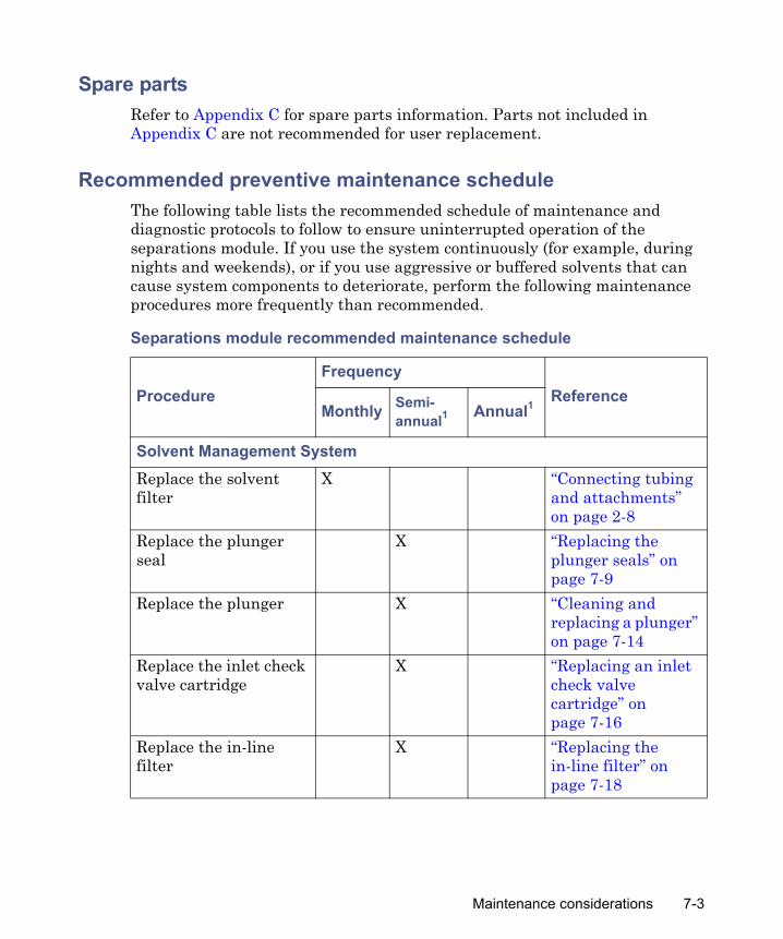
Spare partsRefer to Appendix C for spare parts information. Parts not included in Appendix C are not recommended for user replacement.
Recommended preventive maintenance scheduleThe following table lists the recommended schedule of maintenance and diagnostic protocols to follow to ensure uninterrupted operation of the separations module. If you use the system continuously (for example, during nights and weekends), or if you use aggressive or buffered solvents that can cause system components to deteriorate, perform the following maintenance procedures more frequently than recommended.
Separations module recommended maintenance schedule
ProcedureFrequency
ReferenceMonthly Semi-
annual1 Annual1
Solvent Management SystemReplace the solvent filter
X “Connecting tubing and attachments” on page 2-8
Replace the plunger seal
X “Replacing the plunger seals” on page 7-9
Replace the plunger X “Cleaning and replacing a plunger” on page 7-14
Replace the inlet check valve cartridge
X “Replacing an inlet check valve cartridge” on page 7-16
Replace the in-line filter
X “Replacing the in-line filter” on page 7-18
Maintenance considerations 7-3

Maintaining the solvent management system
Perform the procedures in this section when you discover a problem with a specific component in the solvent management system. For information about isolating problems in the solvent management system, see Chapter 8.
Sample Management SystemReplace the syringe X “Replacing the
syringe” on page 7-22
Replace the injection port seat
X “Replacing the needle assembly” on page 7-27
Rebuild the injector X Appendix C, “Spare Parts”
Rebuild the 3-column selection valve (if installed)
X Appendix C, “Spare Parts”
Rebuild the 6-column selection valve (if installed)
X Appendix C, “Spare Parts”
Rebuild the column regeneration valve (if installed)
X Appendix C, “Spare Parts”
1. Refer to Waters Licenses, Warranties, and Support Services document for information about warranty periods.
Warning: To prevent injury, always observe Good Laboratory Practices when you handle solvents, change tubing, or operate the separations module. Know the physical and chemical properties of the solvents you use. Refer to the Material Safety Data Sheets for the solvents in use.
Separations module recommended maintenance schedule (Continued)
ProcedureFrequency
ReferenceMonthly Semi-
annual1 Annual1
7-4 Maintenance

Overview Maintaining the solvent management system involves these tasks:
• Replacing the plunger seals• Replacing the seal-wash seals• Cleaning and replacing a plunger• Replacing an inlet check valve• Replacing the in-line filter
For a complete list of spare parts, see Appendix C.Tip: To ensure proper drip protection, be sure the solvent delivery and solvent conditioning trays are resecured in place, with screws, before you operate the system.
Solvent management system componentsThe following figure illustrates the solvent management system components (with the solvent delivery tray pulled out).
Maintaining the solvent management system 7-5

Solvent management system components
e2695 solvent management system components
Component FunctionPrimary piston chamber Draws in/expels solvent as part of serial flow
design.Accumulator piston chamber
Draws in/expels solvent as part of serial flow design.
Prime/vent valve Allows solvent purging, priming, and venting.Seal-wash pump Provides solvent to wash the seals of the
primary and accumulator plungers.Primary inlet check valve
Maintains flow direction in the primary piston chamber by opening in one direction only (opens on the plunger intake stroke, closes on the delivery stroke).
����� �
Primary piston chamber
Inlet check valve
Seal-wash pumpPrimarytransducer
Prime/vent valve
Inlet check valve
Accumulator piston chamber
System transducer In-line filter
7-6 Maintenance

Removing the head, seal-wash assembly, and plunger Tip: For information about isolating problems in the solvent management system, see Chapter 8.See the figure on page 7-8 to view the head, head nut, plunger, seal wash assembly, and check valve assembly of each solvent delivery piston chamber. Remove the head, seal-wash assembly, and plunger whenever you need to perform these tasks:
• Replace the plunger seals• Clean or replace a plunger• Service the seal-wash seals
Accumulator inlet check valve
Maintains flow direction in the accumulator piston chamber by opening in one direction only (opens on the plunger intake stroke, closes on the delivery stroke).
Primary transducer Senses backpressure developed by resistance to solvent flow in the primary piston chamber.
System transducer Senses backpressure developed by resistance to solvent flow in the HPLC system.
In-line filter Provides solvent filtering between the solvent management system and the sample management system.
e2695 solvent management system components (Continued)
Component Function
Maintaining the solvent management system 7-7

Piston chamber components
To remove the head, seal-wash assembly, and plunger:
1. On the Main screen, press Diag.
2. In the Diagnostics screen, press Other Tests.
3. From the list in the Other Diagnostics screen, select Head Removal and Replacement.
4. Follow the instructions that appear in the Head Removal and Replacement screen.Requirement: To minimize fluid leakage during the head removal and replacement procedure, make sure that the GPV valve is set to the Off position (see “Motors and Valves diagnostic test” on page 8-7) and place the seal wash reservoir on the same level as the separations module.
5. Remove the head, seal wash assembly, and plunger as one unit (see the figure on page 7-15).
For more information about removing the head, see “Head removal and replacement function” on page 8-17.
Manifold
Plunger cone (shown disengaged)
Check valve cartridge
Check valve housing
Plunger-seal-wash assembly
Head nut
Head
Plunger
7-8 Maintenance

Replacing the plunger seals Notes:
• To ensure optimum performance, replace the plunger seal in any head that you service. Replace the face seals after you replace the plunger seal two or three times (see the figure on page 7-10).
• The standard seals in the separations module perform long and well with most solvents typically used in HPLC separations methods. If you find they perform unsatisfactorily for your applications, contact Waters for alternative plunger seals (part number WAT271066).
This procedure involves replacing these seals: • Plunger seal• Inlet face seal • Outlet face seal
Required materials
• Seal insertion tool (startup kit)• Seal removal tool (part number WAT039803)• Replacement seals• Squeeze bottle with 100% alcohol (methanol or isopropanol)• Clean block, such as a detector cell window (part number WAT097295)• Syringe (startup kit)• Plastic tweezers or can of compressed air
Replacing the plunger seal
To replace the plunger seal:
1. Remove the head as described in “Removing the head, seal-wash assembly, and plunger” on page 7-7.
Caution: To avoid damaging the sealing surfaces, use the seal removal tool. Do not use a sharp tool to remove or install seals.
Maintaining the solvent management system 7-9

2. Use the plastic end of the seal removal tool to remove the plunger seal from the head.
Plunger and face seal orientation
3. Wet the insertion tool, seal opening, and new plunger seal with 100% alcohol before you install the seal.
4. Place the new plunger seal on the seal insertion tool with the spring side facing away from the tool.
5. Insert the tip of the tool into the plunger seal opening in the head, and then push firmly to install the seal.
Face seal replacement
To replace the face seals:
1. Remove the head as described in “Removing the head, seal-wash assembly, and plunger” on page 7-7.
Caution: To avoid damage to the sealing surfaces, use the seal removal tool. Do not use a sharp tool to remove or install seals.
Plunger seal(spring side faces head)
Head
Outlet faceseal
Inlet faceseal
J tube
Head alignment pin
7-10 Maintenance

2. Direct compressed air into the center of the face seal or use plastic tweezers to remove the inlet and outlet face seals from the seal openings in the head (see the figure on page 7-10).
3. Wet the new seals and seal openings with 100% alcohol.
4. Place the new face seals in the face seal openings in the head.
5. Use an alcohol-cleaned, flat object, such as a detector window, to firmly press the face seals into the openings on the pump head.
6. After you replace the seals, view the Head Removal and Replacement screen.
7. Follow the directions on the screen to reinsert the head, seal wash housing, washer, and plunger assemblies. Requirement: To avoid damaging the tube seals, and to properly align the seal wash tubes with the seal wash housing, refer to steps a through d, below. Also, make sure that the head alignment pin is properly oriented and that the “J” tube faces downward (see the figure on page 7-15).
a. After finger tightening the head nut onto the head, loosen (turn counterclockwise) the nut approximately 1/2-turn.
b. Inspect the ends of the seal wash tubes for damage. If necessary, trim the ends with a razor blade.
c. Reinsert the seal wash tubes into the manifold, and then fully tighten the head nut.
d. Return the release ring to the run position.If the separations module’s solvent lines are empty, dry prime the solvent management system to draw solvent into the plunger cavity, before you perform a wet prime or start delivery of solvents (see “Dry priming the system” on page 4-12).
Maintaining the solvent management system 7-11
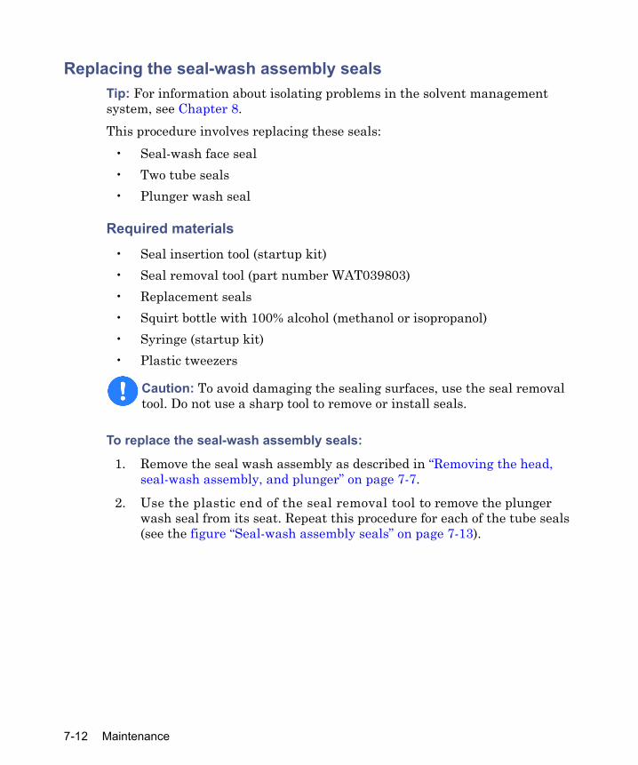
Replacing the seal-wash assembly sealsTip: For information about isolating problems in the solvent management system, see Chapter 8.This procedure involves replacing these seals:
• Seal-wash face seal• Two tube seals• Plunger wash seal
Required materials
• Seal insertion tool (startup kit)• Seal removal tool (part number WAT039803)• Replacement seals• Squirt bottle with 100% alcohol (methanol or isopropanol)• Syringe (startup kit)• Plastic tweezers
To replace the seal-wash assembly seals:
1. Remove the seal wash assembly as described in “Removing the head, seal-wash assembly, and plunger” on page 7-7.
2. Use the plastic end of the seal removal tool to remove the plunger wash seal from its seat. Repeat this procedure for each of the tube seals (see the figure “Seal-wash assembly seals” on page 7-13).
Caution: To avoid damaging the sealing surfaces, use the seal removal tool. Do not use a sharp tool to remove or install seals.
7-12 Maintenance

3. Use the plastic tweezers to remove the seal wash face seal.
Seal-wash assembly seals
4. Wet the seal insertion tool, each new seal, and seal opening with 100% alcohol before you install the seal.
5. Place the new plunger wash seal on the seal insertion tool with the spring side facing away from the seal insertion tool.
6. Insert the tip of the tool into the seal opening, and then push firmly to install the seal. Requirement: Repeat this procedure for each of the tube seals.
7. Install the new seal by pressing the seal into the cavity with your thumb.
8. Reinstall the seal wash housing assembly washer (see the figure on page 7-15).
9. Slide the seal wash housing with washer onto the plunger, and then insert the assembly onto the head (see the figure on page 7-15).
10. Follow the directions in the Head Removal and Replacement screen to reinsert the head, seal wash assembly, and plunger. Requirement: To avoid damaging the tube seals, and to properly align the seal wash tubes with the seal wash housing, refer to steps a through d, below. Also, make sure that the head alignment pin is properly
Seal wash
Tube seal
Tube sealPlunger wash seal
(spring side faces in)
(spring side faces In)(spring side faces In)
face seal
Maintaining the solvent management system 7-13

oriented and that the “J” tube faces downward (see the figure on page 7-15).
a. After finger tightening the head nut onto the head, loosen (turn counterclockwise) the nut approximately 1/2-turn.
b. Inspect the ends of the seal-wash tubes for damage. If necessary, trim the ends with a razor blade.
c. Reinsert the seal wash tubes into the manifold, and then fully tighten the head nut.
d. Return the release ring to the run position.If the separations module’s solvent lines are empty, dry prime the solvent management system to draw solvent into the plunger cavity, before you perform a wet prime or start delivery of solvents (see “Dry priming the system” on page 4-12).
Cleaning and replacing a plunger Tip: For information about isolating problems in the solvent management system, see Chapter 8.
Required materials
• Pumice, fine• Cotton swab• Water, HPLC-grade
Cleaning the plunger
To clean the plunger:
1. Remove the seal wash assembly as described in “Removing the head, seal-wash assembly, and plunger” on page 7-7.
2. Inspect the plunger for damage, excessive wear, or mobile-phase residue without separating it from the pump head and seal wash assembly (see the figure on page 7-15). If the plunger seal has mobile-phase residue, perform these steps:
a. Separate the plunger from the head and seal-wash housing assembly.
7-14 Maintenance

b. Clean the plunger with a fine pumice to remove any coating.
c. Rinse the plunger thoroughly with water to remove all traces of abrasive, then wipe clean.
Plunger, seal-wash, and head
3. Reinspect the plunger. If it shows excessive wear, replace it, and if necessary the plunger seal and face seals as described in “Replacing the plunger seals” on page 7-9.
Replacing the plunger
To replace the plunger:
1. Slide the seal wash housing with washer onto the new plunger, then insert the assembly into the head (see the figure, above).
2. Follow the directions in the Head Removal and Replacement screen to reinsert the head, seal wash assembly, and plunger. Requirement: To avoid damaging the tube seals, and to properly align the seal wash tubes with the seal wash housing, refer to steps a through d, below. Also, make sure that the head alignment pin is properly oriented and that the “J” tube faces downward.
a. After finger tightening the head nut onto the head, loosen (turn counterclockwise) the nut approximately 1/2-turn.
b. Inspect the ends of the seal-wash tubes for damage. If necessary,
Head
Seal-wash
Washer
Plunger
J tube
housing assembly
Maintaining the solvent management system 7-15

use a razor blade to trim the ends.
c. Reinsert the seal wash tubes into the manifold, and then fully tighten the head nut.
d. Return the release ring to the run position.If the separations module’s solvent lines are empty, dry prime the solvent management system to draw solvent into the plunger cavity, before you perform a wet prime or start delivery of solvents (see “Dry priming the system” on page 4-12).
Replacing an inlet check valve cartridgeTip: For information about isolating problems in the solvent management system, see Chapter 8.
Required materials
• Wrench, 1/2-inch, open-end• Wrench, 5/16-inch, open-end • Replacement check valve cartridge• Squirt bottle with 100% alcohol (methanol or isopropanol)• Syringe (startup kit)
To replace an inlet check valve on either piston chamber:
1. In the Other Diagnostics screen, select Motors and Valves. Requirement: Make sure that the GPV valve is set to the Off position (see “Motors and Valves diagnostic test” on page 8-7).
2. Loosen the screws that secure the solvent delivery and solvent conditioning trays, and pull the trays out a few inches to access the check valves (see the figure “Solvent management system components” on page 7-6).
3. Use the 1/2-inch wrench to hold the inlet check valve housing while you disconnect the inlet check valve compression screw with the 5/16-inch wrench (see the figure “Inlet check valve” on page 7-17).
7-16 Maintenance

4. Use the 1/2-inch wrench to disconnect the check valve housing from the manifold.
Inlet check valve
5. Turn the inlet check valve housing upside down to remove the old check valve cartridge.
6. Inspect the inlet check valve housing and clean it if necessary. Wet the housing with 100% alcohol.
7. Wet the new check valve cartridge with 100% alcohol.
8. Insert the replacement check valve cartridge into the inlet check valve housing.Requirement: The arrow on the check valve cartridge must point toward the piston chamber.
9. Insert the inlet check valve housing into the piston chamber housing, and then finger-tighten the check valve housing.
10. Use the 1/2-inch wrench to tighten the inlet check valve housing 1/8-turn.
11. Use the1/2-inch wrench to hold the check valve housing while you reinstall and tighten the compression screw into the check valve housing with the 5/16-inch wrench.
Check valve cartridge
Check valve housing
ManifoldHead
Maintaining the solvent management system 7-17

12. Select Motors and Valves from the Other Diagnostics screen, and press OK to return the GPV to normal state (see “Motors and Valves diagnostic test” on page 8-7).
13. If the separations module’s lines are empty, dry prime the solvent management system to draw solvent into the plunger cavity, before you perform a wet prime or start delivery of solvents (see “Dry priming the system” on page 4-12).
Replacing the in-line filter The in-line filter filters solvent between the solvent management system and the sample management system. Clean and replace the in-line filter element when it is the source of elevated backpressure.Tip: For information about isolating problems in the solvent management system, see Chapter 8.
Required materials
• Wrenches, 5/8-inch, open-end, two• Wrench, 5/16-inch, open-end • Squirt bottle with 100% alcohol (methanol or isopropanol)• Absorbent tissue • Replacement in-line filter element
To replace the in-line filter:
1. Use a 5/8-inch wrench and a 5/16-inch wrench to disconnect the compression screw on the left side of the in-line filter from the inlet housing (see the figure on page 7-19). Tip: Use an absorbent tissue to absorb the small amount of leaked solvent.
2. Use a 5/8-inch wrench to hold the filter outlet housing while you loosen the inlet housing with another 5/8-inch wrench.
3. Invert the inlet housing to remove the in-line filter element.
4. Wet the replacement in-line filter element with alcohol.
7-18 Maintenance

5. Insert the replacement in-line filter element into the in-line filter housing.
Replacing the in-line filter
6. Reconnect the in-line filter inlet and outlet housings.
7. Retighten the compression screw into the inlet housing.
8. Flush the solvent management system with mobile phase at 1 mL/min for 10 minutes.
9. Inspect the in-line filter for leaks, and tighten the fittings as required.
Outlet housingInlet housing
Maintaining the solvent management system 7-19

Maintaining the sample management system
Perform the procedures in this section when you identify a problem with a component of the sample management system.Notes:
• For information about isolating problems in the system, see Chapter 8.• When you remove the separations module’s top or right-hand side-cover
to perform maintenance operations, the XYZ assembly motors can operate only at very slow speeds. This restriction allows you to safely observe the needle and holding loop. Normal operating speeds resume after you reinstall the covers.
Overview Maintaining the sample management system involves these tasks:
• Replacing the syringe• Replacing the needle assembly• Replacing the injection port seat• Replacing the holding loop• Replacing the sample loop• Cleaning the sample compartment and plate carrier
Refer to Appendix C for spare part information. Parts not included in Appendix C are not recommended for user replacement.
Caution: • To prevent injury, always observe Good Laboratory Practices when
you handle solvents, change tubing, or operate the separations module. Know the physical and chemical properties of the solvents you use. Refer to the Material Safety Data Sheets for the solvents in use
• Keep hands or loose clothing clear of the needle assembly mechanism while it is in motion.
7-20 Maintenance
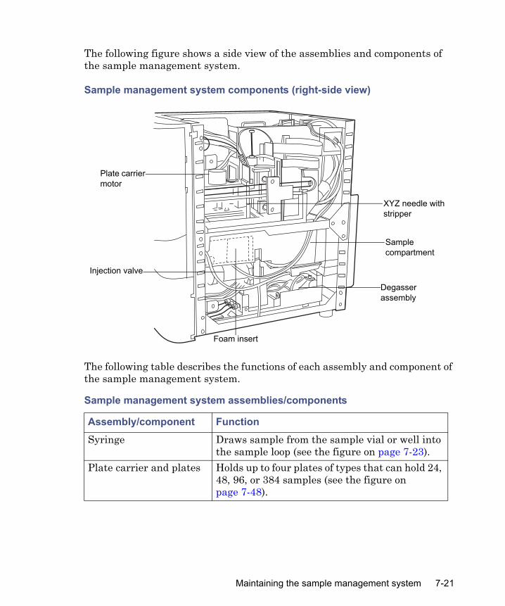
The following figure shows a side view of the assemblies and components of the sample management system.
Sample management system components (right-side view)
The following table describes the functions of each assembly and component of the sample management system.
Sample management system assemblies/components
Assembly/component FunctionSyringe Draws sample from the sample vial or well into
the sample loop (see the figure on page 7-23).Plate carrier and plates Holds up to four plates of types that can hold 24,
48, 96, or 384 samples (see the figure on page 7-48).
TP01585
Sample compartment
Degasser assembly
Injection valve
Plate carrier motor
XYZ needle with stripper
Foam insert
Maintaining the sample management system 7-21

Replacing the syringe
Notes: • To ensure accurate results, use only syringes approved by Waters for use
in the e2795 Separations Module sample management system. See Appendix C for a list of Waters-approved syringes.
• Changing the syringe to one of a different size can also require changing the sample loop and/or holding loop. Refer to the table on page 7-40 for more information.
Replace the syringe under these conditions:• The syringe plunger tip becomes worn or discolored• You want to change to another syringe size (100-, 250-, 500-, 1000-, or
2500-µL)
Injection valve Accepts sample from the injector needle and switches the sample loop in and out of the high-pressure flow. In the Prime position (see the figure on page 1-10), it directs solvent flow to waste.
Sample loop Holds up to one sample-loop volume (50 µL standard) of sample (see the figure on page 7-43).
Holding loop Holds the sample before injection into the sample loop (see the figure on page 7-42).
Needle mounting block Contains sensors that track upward and downward movement of the injector needle (see the figure on page 7-33).
Needle Perforates sample plate film or pre-slit septa, draws sample, and injects it into the flow path through the injection port (see the figure on page 7-31).
Injection port seat Seals needle to the injection port (see the figure on page 7-38).
Sample management system assemblies/components (Continued)
Assembly/component Function
7-22 Maintenance

Required material
Replacement syringe
Removing the syringe
To remove the syringe:
1. Open the syringe compartment door (see the figure on page 1-2).
2. Remove the knurled nut that holds the syringe barrel to the syringe mounting bracket (see the figure on page 7-23).
Syringe assembly components
Caution: Ensure that no injection is in progress or pending when you remove the syringe.
Syringe mounting bracket
Knurled nut
Syringe
Replacing the syringe 7-23
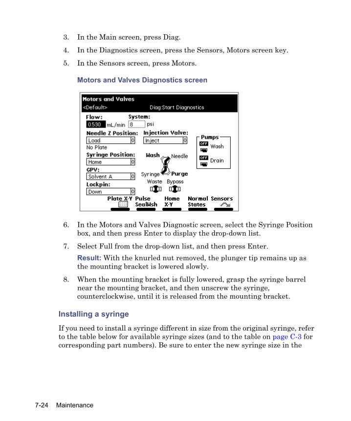
3. In the Main screen, press Diag.
4. In the Diagnostics screen, press the Sensors, Motors screen key.
5. In the Sensors screen, press Motors.
Motors and Valves Diagnostics screen
6. In the Motors and Valves Diagnostic screen, select the Syringe Position box, and then press Enter to display the drop-down list.
7. Select Full from the drop-down list, and then press Enter. Result: With the knurled nut removed, the plunger tip remains up as the mounting bracket is lowered slowly.
8. When the mounting bracket is fully lowered, grasp the syringe barrel near the mounting bracket, and then unscrew the syringe, counterclockwise, until it is released from the mounting bracket.
Installing a syringe
If you need to install a syringe different in size from the original syringe, refer to the table below for available syringe sizes (and to the table on page C-3 for corresponding part numbers). Be sure to enter the new syringe size in the
7-24 Maintenance
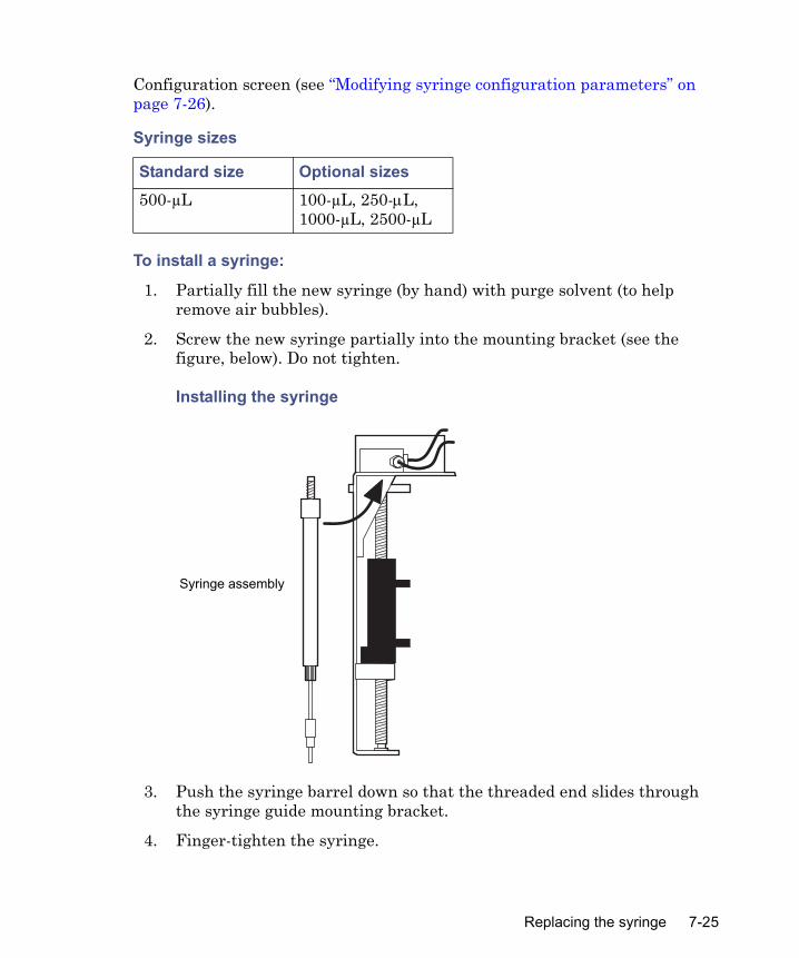
Configuration screen (see “Modifying syringe configuration parameters” on page 7-26).
To install a syringe:
1. Partially fill the new syringe (by hand) with purge solvent (to help remove air bubbles).
2. Screw the new syringe partially into the mounting bracket (see the figure, below). Do not tighten.
Installing the syringe
3. Push the syringe barrel down so that the threaded end slides through the syringe guide mounting bracket.
4. Finger-tighten the syringe.
Syringe sizes
Standard size Optional sizes500-µL 100-µL, 250-μL,
1000-µL, 2500-µL
TP0157
Syringe assembly
Replacing the syringe 7-25

5. On the Motors and Valves diagnostics screen, select Syringe Position, and then press Enter to display the drop-down list.
6. Select Home, and then press Enter. Result: The mounting bracket moves upward to allow you to install the knurled nut.
7. In the Motors and Valves screen, press Exit.
8. In the Diagnostics screen, press Exit twice.
9. Install and finger-tighten the knurled nut.
10. Run the Refresh Syringe function several times to purge any air from the syringe.
Modifying syringe configuration parameters
To configure the separations module for a syringe size that differs from the original size:
1. In the Main screen, press Configure.
2. In the Configuration screen, select Syringe Size.
3. Select the appropriate syringe size from the drop-down list, and then press Enter.Note: When you reconfigure the syringe size, you can possibly need to change the syringe draw rate in your separations method.
4. Press Exit.
Refreshing the syringeAfter you install a syringe, refresh it to remove any bubbles in the system. If you are priming the sample management system for the first time or changing the purge solvent, see “Refreshing the syringe” on page 3-36.Tip: Before refreshing the syringe, ensure the degasser is set to Continuous mode (see “Degassing solvents” on page 3-32).
To refresh the syringe:
1. Press Menu/Status to display the Status screen.
2. Press Direct Functions.
7-26 Maintenance

3. In the Direct Functions menu, select Refresh Syringe, and then press Enter.
4. In the Refresh Syringe dialog box, enter the number of syringe strokes in the “Syringe strokes” box and the replacement volume in the “Replacement volume” of degassed solvent box. Tip: Start with 12 syringe strokes and 600 mL replacement volume.
5. Press OK. Result: The Refresh Syringe cycle begins.
Replacing the needle assemblyTip: When you remove the separations module’s top or right-hand side-cover for maintenance of the sample management system, the XYZ assembly motors can operate only at very slow speeds. This restriction allows you to safely observe the needle and holding loop. Normal operating speeds resume after you reinstall the covers.
Replace the needle assembly when any of these conditions are present: • Contaminant peaks that appear in the chromatogram and cannot be
corrected by changing the wash solvent in the needle-wash system• Chromatographic peak heights that vary unexpectedly, the result of any
of the following conditions:– Bent needle– Damaged needle tip– Plugged needle– Worn inject port seat (see “Replacing the injection port seat” on
page 7-33)
Warning: To prevent injury, keep hands or loose clothing clear of the needle assembly mechanism while it is in motion.
Replacing the syringe 7-27
Removing the needle assembly
Required materials• Wrench, 5/16-inch (2)• Screwdriver, 1/4-inch flat-blade, short
• Phillips® head screwdriver, #2 regular
To remove the needle assembly:
1. Power-off the separations module.
2. Remove the column heater or column heater/cooler if installed, and then power-on the separations module.
3. Remove the separations module’s top and right-hand side panels.
4. In the Main screen, press the Diag screen key, and then press Other Diags.
5. In the Other Diagnostics drop-down list, select Change needle. Result: A message appears requesting that you remove the plates from the carrier.
6. After removing the plates from the carrier, press OK. Result: The screen displays a message stating the needle is being positioned for replacement.
7-28 Maintenance
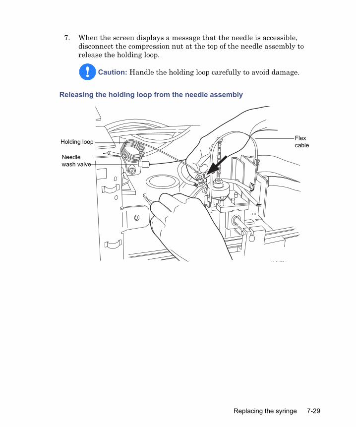
7. When the screen displays a message that the needle is accessible, disconnect the compression nut at the top of the needle assembly to release the holding loop.
Releasing the holding loop from the needle assembly
Caution: Handle the holding loop carefully to avoid damage.
������
Holding loop
Needle wash valve
Flex cable
Replacing the syringe 7-29

8. Use a screwdriver to loosen the two captive screws from the needle holder block.
Loosening two captive screws in needle-holder block
Installing the needle assembly
Required materials• e2795 separations module needle and housing assembly (part number
700000388)• Screwdriver, 1/4-inch flat-blade, short
Warning: To prevent injury or equipment damage, do not touch or press the end of the PEEK tube stripper (see the figure on page 7-31). Doing so breaks the needle free from the tubing and can cause a puncture wound.
Flex cable
Needle mounting block
Needle assembly
Needle holder block
7-30 Maintenance

To install the needle assembly:
1. Grasp the new needle assembly below the bushings (but above the PEEK tube) on the assembly (see the figures on page 7-31 and page 7-32).
e2795 separations module needle assembly
2. Slide the spring-loaded washer under the “fingers” on the needle-mounting block. Make sure the flag on the replacement needle
Flag
Union
Spring-loaded washer
Needle
Compliance spring
Bushings
Stripper springs
PEEK tube (stripper)
Replacing the syringe 7-31
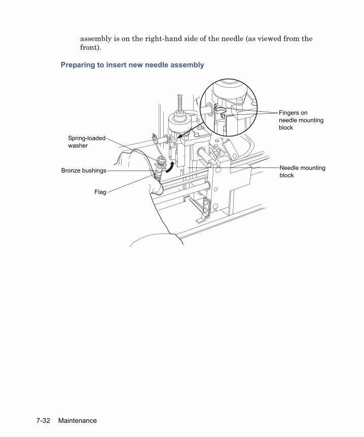
assembly is on the right-hand side of the needle (as viewed from the front).
Preparing to insert new needle assembly
������
Needle mounting block
Fingers on needle mounting block
Bronze bushings
Spring-loaded washer
Flag
7-32 Maintenance

3. Move the replacement needle up slightly, and then into the recess in the needle mounting block.
Inserting the new needle into the needle-mounting block
4. Reinstall the needle-holder block; tighten the screws until snug.
5. Reconnect the existing holding loop, or install a new one (see “Replacing the holding loop” on page 7-40).
6. When you complete replacing the needle assembly, press OK.Result: The separations module displays a message indicating that it is rehoming the needle.
Replacing the injection port seat
When you observe contaminant peaks that you cannot correct by changing the wash solvent in the needle-wash system or chromatographic peak heights that vary unexpectedly, a worn inject port seat can be the cause (see “Replacing the needle assembly” on page 7-27, for other possible causes).
Caution: To prevent damaging the needle during replacement of the inject port seat, perform the Change Needle procedure (see “Replacing the needle assembly” on page 7-27) before you remove the injection port seat.
Needle mounting block
Replacing the syringe 7-33

Recommendation: Replace the injection-port-seal washer if it is leaking or blocking the injection port flow path. If you need to replace the washer, do it at the same time you replace the injection port seat. See the “Replacing the injection-port-seal washer” on page 7-39 discussion below.
Required materials
• e2795 separations module injection port seat (part number 700000384)• e2795 injection port seal washer (part number 700000385)• Wrench, 5/8-inch, open-end
• T-20 TORX® wrench or driver• Phillips head screwdriver, #2 regular• Wrench, 1/4-inch, open-end• Allen wrench, 3-mm
Removing the injection port seat
To remove the injection port seat:
1. Power-off the separations module, and remove the column heater or column heater/cooler, if installed, and then the right-hand side panel.
2. Remove the foam insulation block from the sample compartment (see the figure, below).
7-34 Maintenance

3. Use the Allen wrench to loosen the two captive screws on the front panel, and then remove the front panel.
Right-hand side view of sample compartment with foam insulation block removed
TP01601
Injection valve
Rear check valve mounting bracket
Injection valve bracket mounting screw
Replacing the syringe 7-35

4. Use the screwdriver to loosen the captive screw under the sample compartment, and then remove the right front panel mounting bracket (see the figure, below).
Loosening the screw from the right-hand, front panel mounting bracket
5. Use the 1/4-inch open-end wrench to remove the tubing connection from the #6 port on the injection valve.
6. Use the 5/8-inch open-end wrench to loosen (clockwise) the reverse-threaded nut under the needle-wash housing.
7. While holding the injection valve, use the T-20 Torx wrench to remove the valve bracket mounting screw, at the rear of the valve, and then lower the valve from its housing.
Captive screw on front panel mounting bracket
7-36 Maintenance

8. Remove the injection port seat from the injection port (see the figure on page 7-38).
Loosening reverse-threaded nut under needle-wash housing
Turn clockwise to loosen
Reverse- threaded nut
#6 Port connection(shown removed)
Injection valve
Replacing the syringe 7-37
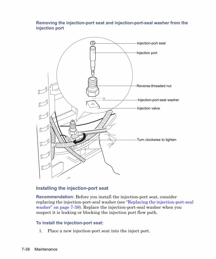
Removing the injection-port seat and injection-port-seal washer from the injection port
Installing the injection-port seat
Recommendation: Before you install the injection-port seat, consider replacing the injection-port-seal washer (see “Replacing the injection-port-seal washer” on page 7-39). Replace the injection-port-seal washer when you suspect it is leaking or blocking the injection port flow path.
To install the injection-port seat:
1. Place a new injection-port seat into the inject port.
Turn clockwise to tighten
Injection-port seat
Injection port
Reverse-threaded nut
Injection-port-seal washer
Injection valve
7-38 Maintenance
2. Hold the inject valve level to reposition it under the sample compartment, then raise the valve and injection port into the needle-wash housing.
3. While holding the valve and injection port with one hand, thread the reverse-threaded nut up into the wash housing until finger-tight.
4. Use the 5/8-inch open-end wrench to tighten the nut, turning it counterclockwise. Do not overtighten.
5. While continuing to hold the injection valve, reinstall the valve bracket mounting screw (see the figure on page 7-35).
6. Use the 1/4-inch wrench to reconnect the tubing to the #6 port on the injection valve.
7. Reinstall the foam insulation block.
8. Reinstall the front panel mounting bracket and the front panel.
9. Reinstall the side panel and the column heater.
10. Power-on the separations module.
Replacing the injection-port-seal washer
Recommendation: Replace the injection-port-seal washer when you suspect it is leaking or blocking the injection port flow path.
Required materials• Wrench, 3/16-inch open-end• Dental pick or sharp tweezers• Inject-port-seal washer (see Appendix C)
To remove and replace the injection-port-seal washer:
1. Follow the instructions to remove the injection-port seat above.
2. When you remove the injection valve from the separations module, perform these steps:
a. Use the 3/16-inch wrench to loosen the inject port, and then remove it from the injection valve.
b. Use the dental pick or tweezers to remove the old injection-port-seal washer from the bottom of the inject valve body.
Replacing the syringe 7-39

c. Use your fingers (or a soft-tipped tool) to insert the new seal washer carefully into the injection valve body.Note: Inspect carefully to ensure that the washer lies flat on the bottom of the injection valve body cavity.
d. Reinstall the injection port and injection-port seat as instructed in the “Installing the injection-port seat” on page 7-38.
Replacing the holding loopNotes:
• To avoid sample carryover or contamination of solvent, Waters recommends that you replace the holding loop and sample loop at the same time and according to the size compatibility information provided in the following table.
• To reduce cycle time and sample size, and to optimize accuracy, ensure that the total sample volume never exceeds two-thirds the capacity of the holding loop.
Recommended syringe, sample, and holding loopcombinations
Syringe volume(μL)
Sample loop volume (μL)
Holding loop volume (μL)
Holding loop color
Purge solvent (replacement)volume (μL)
Cycles (# of syringe strokes)1
500 (standard)
52050
128128128
OrangeOrangeOrange
300 or 600300 or 600300 or 600
1 or 21 or 21 or 2
100 520
128128
OrangeOrange
300 or 600300 or 600
5 or 105 or 10
250 520
128128
OrangeOrange
300 or 600300 or 600
2 or 42 or 4
1000 52050100
128128128500
OrangeOrangeOrangeRed
6006006001200
1112
7-40 Maintenance

Required materials
• Wrench, 5/16-inch, open-end (2)• Screwdriver, 1/4-inch flat-blade, short• Holding loop (see the table, above)
To remove and replace the holding loop:
1. Power-off the separations module.
2. Remove the column heater or column heater/cooler if installed and the separations module’s top and right-hand side panels.
3. Use two 5/16-in. wrenches to loosen the stainless steel compression nut at the top of the needle assembly.
2500 520501005002000
12812812850030003000
OrangeOrangeOrangeRedTanTan
600600600150060006000
<1<1<1144
1. Entering a purge volume (Replacement Volume of Degassed Solvent) of 600 mL in the Autosampler Wash screen when you are editing a separation method (see “Setting autosam-pler parameter values” on page 5-16) thoroughly flushes the needle and holding loop with fresh, degassed purge solvent. However, to minimize cycle time, you can enter 300 mL in the Replacement Volume box because 300 mL provides acceptable injection volume repeatability and reduces cycle time by approximately 15 seconds.
Recommended syringe, sample, and holding loopcombinations (Continued)
Syringe volume(μL)
Sample loop volume (μL)
Holding loop volume (μL)
Holding loop color
Purge solvent (replacement)volume (μL)
Cycles (# of syringe strokes)1
Replacing the syringe 7-41
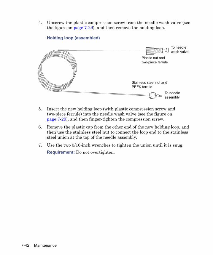
4. Unscrew the plastic compression screw from the needle wash valve (see the figure on page 7-29), and then remove the holding loop.
Holding loop (assembled)
5. Insert the new holding loop (with plastic compression screw and two-piece ferrule) into the needle wash valve (see the figure on page 7-29), and then finger-tighten the compression screw.
6. Remove the plastic cap from the other end of the new holding loop, and then use the stainless steel nut to connect the loop end to the stainless steel union at the top of the needle assembly.
7. Use the two 5/16-inch wrenches to tighten the union until it is snug. Requirement: Do not overtighten.
To needle assembly
Stainless steel nut and PEEK ferrule
To needle wash valve
Plastic nut and two-piece ferrule
7-42 Maintenance

Replacing the sample loopRecommendation: To avoid sample carryover or solvent contamination, replace the holding loop and sample loop at the same time and according to the information provided in the table on page 7-40.
Sample loop (assembled)
Required materials
• Allen wrench, 3-mm• Wrench, 1/4-inch, open-ended• T-20 TORX wrench or driver• Stainless steel sample loop and fittings
To remove and replace the sample loop:
1. Open the solvent delivery and solvent conditioning tray access doors.
To ports 5 and 8 on injection valve
Replacing the syringe 7-43
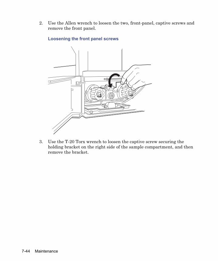
2. Use the Allen wrench to loosen the two, front-panel, captive screws and remove the front panel.
Loosening the front panel screws
3. Use the T-20 Torx wrench to loosen the captive screw securing the holding bracket on the right side of the sample compartment, and then remove the bracket.
7-44 Maintenance
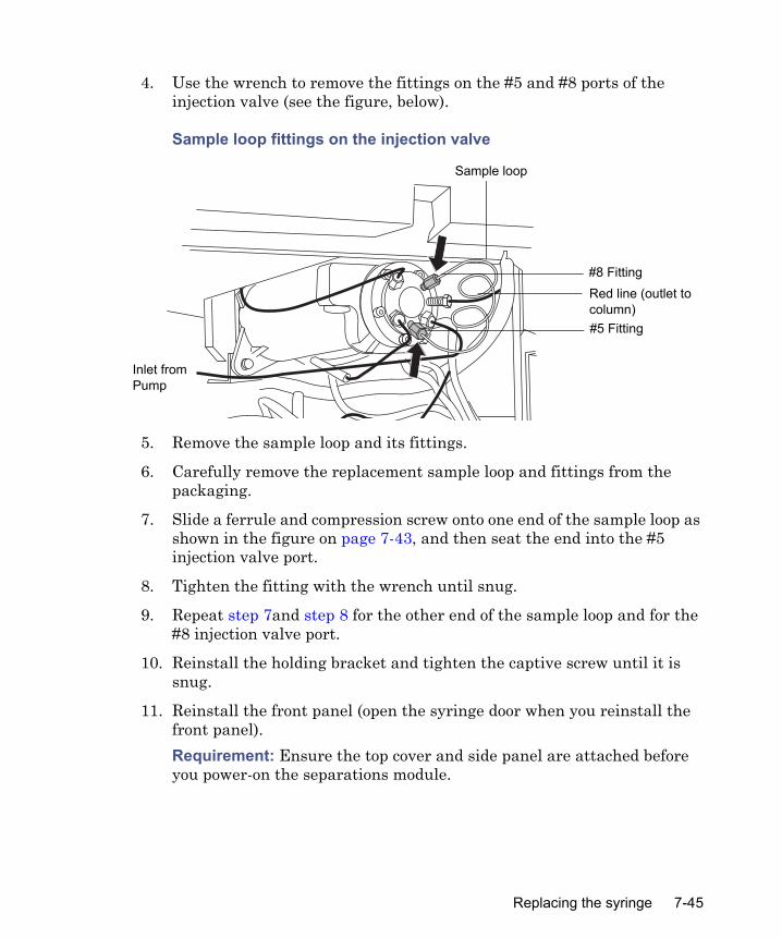
4. Use the wrench to remove the fittings on the #5 and #8 ports of the injection valve (see the figure, below).
Sample loop fittings on the injection valve
5. Remove the sample loop and its fittings.
6. Carefully remove the replacement sample loop and fittings from the packaging.
7. Slide a ferrule and compression screw onto one end of the sample loop as shown in the figure on page 7-43, and then seat the end into the #5 injection valve port.
8. Tighten the fitting with the wrench until snug.
9. Repeat step 7and step 8 for the other end of the sample loop and for the #8 injection valve port.
10. Reinstall the holding bracket and tighten the captive screw until it is snug.
11. Reinstall the front panel (open the syringe door when you reinstall the front panel).Requirement: Ensure the top cover and side panel are attached before you power-on the separations module.
#8 FittingRed line (outlet to column)#5 Fitting
Sample loop
Inlet from Pump
Replacing the syringe 7-45

Cleaning the sample compartment and plate carrierClean the sample compartment and plate carrier when these conditions arise:
• The sample plates do not rotate properly• The plate carrier does not engage• A spill occurs
Required materials
• Allen wrench, 3-mm• Non-abrasive cleaner
Accessing the sample compartment
To access the sample compartment:
1. Open the sample compartment door.
2. Use the screen keys in the Door Is Open dialog box to move the plate carrier to the #1 (blue) position (see “Loading the sample plates” on page 3-38).
7-46 Maintenance
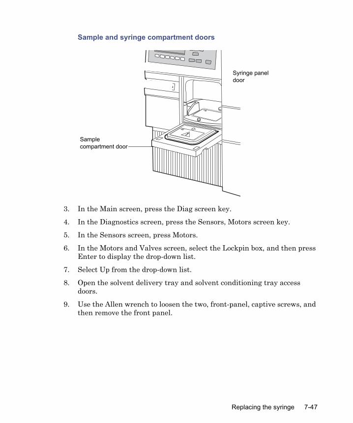
Sample and syringe compartment doors
3. In the Main screen, press the Diag screen key.
4. In the Diagnostics screen, press the Sensors, Motors screen key.
5. In the Sensors screen, press Motors.
6. In the Motors and Valves screen, select the Lockpin box, and then press Enter to display the drop-down list.
7. Select Up from the drop-down list.
8. Open the solvent delivery tray and solvent conditioning tray access doors.
9. Use the Allen wrench to loosen the two, front-panel, captive screws, and then remove the front panel.
���������������������������
Sample compartment door
Syringe panel door
Replacing the syringe 7-47

Cleaning the sample compartment and carrier
To clean the sample compartment and carrier:
1. Push down about 1/4-inch on the spring-retaining pin in the center of the plate carrier to disengage the carrier from the drive shaft.
Sample plate carrier
2. While lifting the front edge of the plate carrier slightly, slide the carrier toward you and remove the carrier.
3. Using a nonabrasive cleaner, clean and then dry the carrier and the carrier floor plate (which remains attached to the floor of the sample compartment).
4. Position the plate carrier so the #1 (blue) position is facing you (see “Loading the sample plates” on page 3-38).
Warning: To prevent injury to yourself or damage to the equipment, do not bend or detach the plate-positioner spring located in the rear of the sample compartment (see the figure on page 7-48).
Spring-retaining pin
Plate-positioner spring
7-48 Maintenance

5. Reinstall the carrier by sliding the carrier into the sample compartment while pushing down about 1/4 inch on the spring-retaining pin in the center of the carrier.
6. Rotate the carrier a little in both directions to ensure the pin is engaged in the slot in the drive shaft.
7. Using the Allen wrench, reinstall the sample compartment front panel.
8. In the Motors and Valves diagnostics screen, select the Lockpin box, press Enter to display the drop-down list, and then select Down from the drop-down list.
9. Press Exit to exit from the Motors and Valves screen. Press Exit again to return to the Diagnostics screen.
Replacing the syringe 7-49

7-50 Maintenance
8 Diagnostic Testing and Troubleshooting
Contents
Topic PageOverview 8-2Safety and handling 8-2Using the error log 8-3Performing main diagnostic tests 8-3Performing other diagnostic tests 8-12Troubleshooting 8-23
8-1
Overview
You troubleshoot the separations module with the help of diagnostic tests and the recommended troubleshooting procedures described in this chapter. Tip: For information about startup diagnostics, see “Startup diagnostic tests” on page 3-2.
Proper operating proceduresTo ensure your separations module runs as designed, follow the operating procedures and guidelines described in Chapter 3.
Reinitializing the systemReinitialize the system instruments at least once a week. To do so, power-off the separations module, transfer module, baths, and detectors for a minimum of 1 minute, and then power-on each instrument. This procedure helps ensure that the mechanical and electrical components, as well as internal firmware, synchronize for proper operation.
Spare partsRefer to Chapter C for spare parts information. Parts not included in Appendix C are not recommended for replacement by the customer.
Safety and handling
When you troubleshoot the separations module, keep the following safety considerations in mind:
Warning: To avoid electric shock,• Never disconnect an electrical assembly while power is applied to the
bioseparations module. After power is turned off, wait approximately ten seconds before you disconnect an assembly.
• To avoid the possibility of electric shock, do not open the power supply cover. The power supply does not contain user-serviceable parts.
8-2 Diagnostic Testing and Troubleshooting
Using the error log
In the error log, view the status messages and warnings that the separations module generated. You can view or print the information to help track possible problems that occurred during system operation.Requirement: To print the error log, connect a serial printer to the RS-232 serial port on the separations module’s rear panel (see “RS-232 connections” on page 2-27).Press the Log screen key in the Main screen to display the Error Log screen.The Error Log screen displays the last 10 messages, in chronological order, the most recent message appearing at the bottom of the screen. Use the Page key or the “up” arrow key to view older messages. The error log can save as many as 100 messages.Press the Refresh screen key to display any messages logged since the screen was last accessed.If printing is configured, press the Print screen key to print the error log to a printer configured for the separations module.The table on page 8-38 provides a list of some of the most commonly encountered error messages.
Performing main diagnostic tests
You can perform many diagnostic operations from two diagnostics screens: • Diagnostics screen – Accesses certain system status information and
diagnostic and performance tests for the solvent management system and the sample management system; also accesses utilities for Waters Technical Service representatives.
Warning: To prevent injury, always observe Good Laboratory Practices when you handle solvents, change tubing, or operate the separations module. Know the physical and chemical properties of the solvents you use. Refer to the Material Safety Data Sheets for the solvents in use.
Caution: To prevent circuit damage due to static charges, do not touch integrated circuit chips or other components that do not specifically require manual adjustment.
Using the error log 8-3

• Other Diagnostics screen – Accesses diagnostic tests and functions that allow the user to perform maintenance procedures and control optional devices (such as the column heater, column heater/cooler, and sample heater/cooler). For more information, see “Performing other diagnostic tests” on page 8-12.
To access the Diagnostics screen, press the Diag screen key in the Main screen. The Diagnostics screen appears.
Diagnostics screen
Press the screen key corresponding to the part of the separations module you want to troubleshoot.The following table describes the functions of the screen keys in the main Diagnostics screen.
Diagnostics screen keys
Screen key Function ReferencePrime SealWsh
Primes the solvent management system plunger-seal-wash pump
“Priming the plunger-seal-wash pump” on page 8-5
Prime Ndl Wash
Primes the sample management system needle wash valve and tubing
“Priming the needle-wash pump” on page 8-5
C99SM9000N
8-4 Diagnostic Testing and Troubleshooting
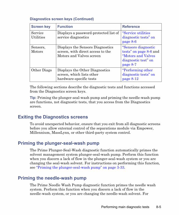
The following sections describe the diagnostic tests and functions accessed from the Diagnostics screen keys.Tip: Priming the plunger-seal-wash pump and priming the needle-wash pump are functions, not diagnostic tests, that you access from the Diagnostics screen.
Exiting the Diagnostics screensTo avoid unexpected behavior, ensure that you exit from all diagnostic screens before you allow external control of the separations module via Empower, Millennium, MassLynx, or other third-party system control.
Priming the plunger-seal-wash pumpThe Prime Plunger-Seal-Wash diagnostic function automatically primes the solvent management system plunger-seal-wash pump. Perform this function when you discern a lack of flow in the plunger-seal-wash system or you are changing the seal-wash solvent. For instructions on performing this function, see “Priming the plunger-seal-wash pump” on page 3-33.
Priming the needle-wash pumpThe Prime Needle Wash Pump diagnostic function primes the needle wash system. Perform this function when you discern a lack of flow in the needle-wash system, or you are changing the needle-wash solvent. For
Service Utilities
Displays a password-protected list of service diagnostics
“Service utilities diagnostic tests” on page 8-6
Sensors, Motors
Displays the Sensors Diagnostics screen, with direct access to the Motors and Valves screen
“Sensors diagnostic tests” on page 8-6 and “Motors and Valves diagnostic test” on page 8-7
Other Diags Displays the Other Diagnostics screen, which lists other hardware-specific tests
“Performing other diagnostic tests” on page 8-12
Diagnostics screen keys (Continued)
Screen key Function Reference
Performing main diagnostic tests 8-5

instructions on performing this function, see “Priming the needle-wash pump” on page 3-35.
Service utilities diagnostic testsService Utilities diagnostic tests are for use by Waters field service engineers only and are password-protected.
Sensors diagnostic testsThe Sensors diagnostics screen displays the current position of the digital and other sensors for the separations module.
To display the Sensors diagnostics:
1. In the Diagnostics screen, press Other Diags.
2. In the Other Diagnostics screen, press the Sensors, Motors screen key. The Sensors Diagnostics screen appears indicating the current position of these components: • Inject Valve – “Inject”, “Load”, or “Prime” is displayed in the pane
with sensor codes of 0, 1, 2, and 3. The four sensors form a binary code that identifies the current position of the injection valve. For example, if the sensors are read left to right as Off, Off, Off, On (or 0001), this indicates the injection valve is in position 1, the injection position. A “sensors” condition exists if no position (0, 1, 2, or 3) for the injection valve is indicated (see the table on page 8-38).
• Carrier – Position, Home, Lockpin• Autosampler – Needle top, Needle bottom, Syringe emptyIn addition, the other sensors indicate these operational states:• Door Open – Sample compartment door is open• Interlock – Safety interlock is engaged• X home – Needle is in the X home position• Y home – Needle is in the Y home position
8-6 Diagnostic Testing and Troubleshooting

Sensors diagnostic screen
3. To display the normal (default) states for all three sensors, press Normal States.To display the Motors Diagnostics screen, press Motors.
4. Press Exit to return to the Other Diagnostics screen.
Motors and Valves diagnostic testThe Motors and Valves test results inform you regarding whether the parameter values you assign to motors and valves fall within limits acceptable for protecting the system and column. The test checks these components:
• Motors:– Needle drive (4 positions)– Syringe drive (3 positions)– Lockpin (2 positions)
• Solenoid valves:– Gradient proportioning valve (GPV)– Wash valve (3-way)– Purge valve (3-way)
Performing main diagnostic tests 8-7
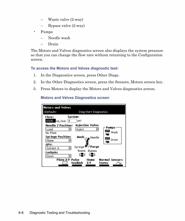
– Waste valve (2-way)– Bypass valve (2-way)
• Pumps– Needle wash– Drain
The Motors and Valves diagnostics screen also displays the system pressure so that you can change the flow rate without returning to the Configuration screen.
To access the Motors and Valves diagnostic test:
1. In the Diagnostics screen, press Other Diags.
2. In the Other Diagnostics screen, press the Sensors, Motors screen key.
3. Press Motors to display the Motors and Valves diagnostics screen.
Motors and Valves Diagnostics screen
8-8 Diagnostic Testing and Troubleshooting

Controlling motors
To control the position of the needle or syringe:
1. In the Motors and Valves diagnostics screen, select the motor position parameter (Needle-Z Position or Syringe Position) that you want to change.
2. Press Enter to display a drop-down list of parameter values.
3. Select the needle and/or syringe positions, and then press Enter to save your selection.The following tables describe the position selections available for the needle (injector) and the syringe motors.
4. Press Normal States to return the motors and valves to their idle (default) positions.
Needle (Injector) Z Motor position values
Needle Z motor position Description
Up Needle is raised to maximum height (home).Well Needle tip is at the level of the bottom of the well.Load Needle is moved to injection port seat until needle
bottom is sensed.Wash Needle tip is 1/8-inch above the injection port seat.
Syringe motor position values
Syringe motor position Description
Empty Syringe is in the highest position to purge the syringe.
Home Syringe is in the home (default) position (approximately 20% full).
Full Syringe is in the lowest permitted position (80% full) to draw in sample.
Performing main diagnostic tests 8-9

Controlling the injection valve
To control the position of the injection valve:
1. In the Motors and Valves diagnostics screen, select the Injection Valve position parameter.
2. Press Enter to display a drop-down list of Injection Valve parameter values. The table below describes the values available in the drop-down list.
3. Select the injection valve position, and then press Enter to save your selection.
4. Press Normal States to return the motors and valves to their idle (default) positions.
Controlling the gradient proportioning valve
To control the gradient proportioning valve (GPV):
1. In the Motors and Valves diagnostics screen, select the GPV check box.
2. Press Enter to display a drop-down list of valve positions. The table below describes the valve positions available in the GPV drop-down list.
3. Select the GPV position, and then press Enter to save your selection.
Injection valve position values
Injection valve position Description
Inject Inject sample positionLoad Load sample positionPrime Prime needle wash position
Gradient Proportioning Valve (GPV) position parameters
GPV position DescriptionOff GPV closed (all solvent positions
closed)
8-10 Diagnostic Testing and Troubleshooting
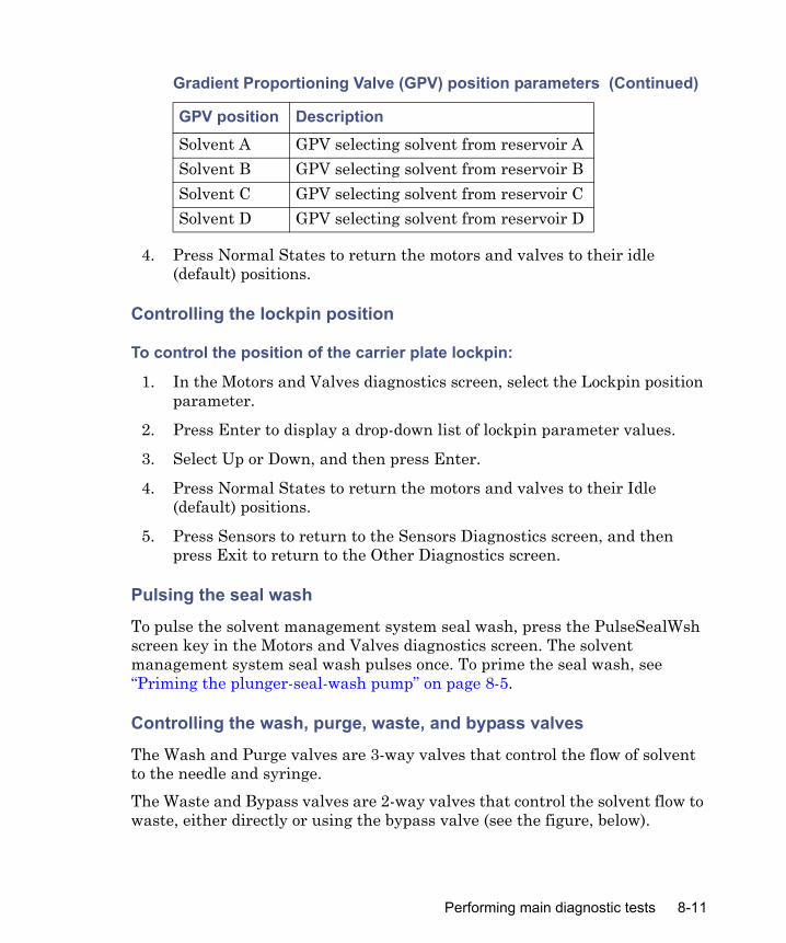
4. Press Normal States to return the motors and valves to their idle (default) positions.
Controlling the lockpin position
To control the position of the carrier plate lockpin:
1. In the Motors and Valves diagnostics screen, select the Lockpin position parameter.
2. Press Enter to display a drop-down list of lockpin parameter values.
3. Select Up or Down, and then press Enter.
4. Press Normal States to return the motors and valves to their Idle (default) positions.
5. Press Sensors to return to the Sensors Diagnostics screen, and then press Exit to return to the Other Diagnostics screen.
Pulsing the seal wash
To pulse the solvent management system seal wash, press the PulseSealWsh screen key in the Motors and Valves diagnostics screen. The solvent management system seal wash pulses once. To prime the seal wash, see “Priming the plunger-seal-wash pump” on page 8-5.
Controlling the wash, purge, waste, and bypass valves
The Wash and Purge valves are 3-way valves that control the flow of solvent to the needle and syringe.The Waste and Bypass valves are 2-way valves that control the solvent flow to waste, either directly or using the bypass valve (see the figure, below).
Solvent A GPV selecting solvent from reservoir ASolvent B GPV selecting solvent from reservoir BSolvent C GPV selecting solvent from reservoir CSolvent D GPV selecting solvent from reservoir D
Gradient Proportioning Valve (GPV) position parameters (Continued)
GPV position Description
Performing main diagnostic tests 8-11

To change the positions of the wash, purge, waste, and bypass valves:
1. In the Motors and Valves diagnostics screen, use the arrow keys to select the Wash, Purge, Waste, or Bypass valve. Tip: A dotted line surrounds the selected valve.
2. Use any key to change the position of the valve from open to closed, or vice versa. Press any key again to return the valve to its original position.
The following figure shows the Wash and Purge valves in three different operational positions, and the Waste and Bypass valves open and closed.
Separations module valve positions
Performing other diagnostic tests
Additional diagnostics tests and functions are available in the Other Diagnostics screen. Some tests in the Other Diagnostics drop-down list are specific to the options installed on the separations module.
To access the Other Diagnostics screen:
1. In the Main screen, press the Diag screen key, and then press Other Diags.
3-way valves with flow from syringe to needle (normal operating position)
3-way valves with flow from wash solvent to needle (needle wash position)
3-way valves with flow from purge solvent to syringe (refresh syringe position)
Waste valve open Bypass valve open
8-12 Diagnostic Testing and Troubleshooting

Other Diagnostics screen
The following table describes the tests available in the Other Diagnostics screen drop-down list.
Other diagnostic tests and functions
Test name Function ReferenceStatic leak test
Tests for leaks in all the seals and fittings in the high-pressure part of the solvent management system.
“Performing the static leak test” on page 8-15
Head removal and replacement
Moves either solvent management system plunger into its most forward position to allow for removal of the head and replacement of the plunger and seal-wash assembly.
“Head removal and replacement function” on page 8-17
Inputs and outputs
Displays the current status of the I/O terminals.
“Performing the Input and Output diagnostics” on page 8-17
Keypad Tests the keys on the front panel keypad.
“Performing the keypad diagnostic test” on page 8-19
Performing other diagnostic tests 8-13
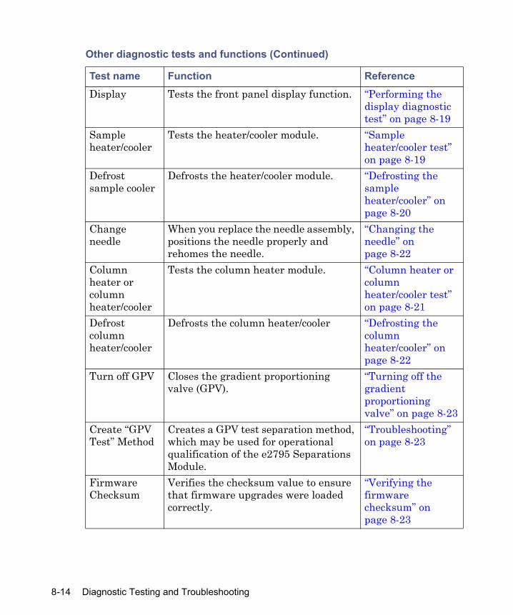
Display Tests the front panel display function. “Performing the display diagnostic test” on page 8-19
Sample heater/cooler
Tests the heater/cooler module. “Sample heater/cooler test” on page 8-19
Defrost sample cooler
Defrosts the heater/cooler module. “Defrosting the sample heater/cooler” on page 8-20
Change needle
When you replace the needle assembly, positions the needle properly and rehomes the needle.
“Changing the needle” on page 8-22
Column heater or column heater/cooler
Tests the column heater module. “Column heater or column heater/cooler test” on page 8-21
Defrost column heater/cooler
Defrosts the column heater/cooler “Defrosting the column heater/cooler” on page 8-22
Turn off GPV Closes the gradient proportioning valve (GPV).
“Turning off the gradient proportioning valve” on page 8-23
Create “GPV Test” Method
Creates a GPV test separation method, which may be used for operational qualification of the e2795 Separations Module.
“Troubleshooting” on page 8-23
Firmware Checksum
Verifies the checksum value to ensure that firmware upgrades were loaded correctly.
“Verifying the firmware checksum” on page 8-23
Other diagnostic tests and functions (Continued)
Test name Function Reference
8-14 Diagnostic Testing and Troubleshooting
Performing the static leak testThe static leak test performs a solvent pressure ramp up, and monitors the pressure decay in the solvent delivery system to determine whether the inlet check valves, tubing, fittings, or plunger seals are faulty Perform the static leak test when these conditions apply:
• You suspect leakage in the inlet check valves or plunger seals.• You performed maintenance on the solvent management system.• You replaced fittings in the flow path.
Required materials• Pin plug• Wrenches, 5/16-inch, open-end, two• Wrench, 7/16-inch, open-end• Waste container
To ensure a successful static leak test, precondition the solvent management system.Tip: if you ran concentrated buffers through the system, use water to flush the system with several wet primes. 100% degassed water is recommended as solvent A.
To precondition the solvent management system:
1. Ensure that solvent A is 100% methanol or 100% degassed water. The separations module selects Solvent A for the static leak test. If solvent A is not methanol or water, flush the solvent A line with either one.
2. Place a restrictor at the in-line filter outlet to produce 20684 to 27579 kPa (207 to 276 bar, 3000 to 4000 psi) at a flow rate of 1.0 to 1.5 mL/min. for 10 minutes. Requirement: Keep the in-line degasser in On mode throughout the preconditioning phase.
To perform the static leak test:
1. In the Other Diagnostic screen, select Static Leak Test, and then press OK.
2. Follow the instructions in the Static Leak Test screen.
Performing other diagnostic tests 8-15

3. Disconnect the tubing at the outlet of the in-line filter, and loosely insert the pin plug into the in-line filter outlet.
4. Collect the solvent runoff in an appropriate waste container.
5. Press Continue after you insert the pin plug.
6. Follow the instructions in the subsequent Static Leak Test screens to complete the test.
When the test ends, the Static Leak Test Results screen appears.
Failing result
If the static leak test indicates a failing result, confirm these things
• No obvious leaks exist.• The prime/vent valve is closed.• The degasser is set to On.• Compression fittings and head nuts are tight.• The appropriate solvent (methanol or water is recommended) was used.• If necessary, ensure a good seal around the plunger and head surface by
flowing at high pressure before rerunning the test. For example, install a restrictor sufficient to achieve 20684 to 27579 kPa (207 to 276 bar, 3000 to 4000 psi) backpressure at a flow rate of 0.5mL/min.
• Finally, repeat the static leak test.
Continued failing result
Take these actions if the static leak test continues to fail:
1. Ensure that the degasser is set to On.
2. Perform a wet prime for 10 minutes, at 1.0 mL/min, using methanol or water and an in-line restrictor to achieve 27579 to 31026 kPa (276 to 310 bar, 4000 to 4500 psi) backpressure.
3. After 7 to 8 minutes of wet priming, inspect the plumbing and fittings for leaks. Use thermal paper, which turns dark on contact with methanol, to detect leaks. Repair any leaks.
4. Remove the restrictor, replacing it with a pin plug, and rerun the static leak test.
8-16 Diagnostic Testing and Troubleshooting

5. If the Accumulator chamber passes the static leak test but exhibits a high decay rate (> 100 psi) and the primary chamber shows a negative pressure value, reverse the position of the check valves (accumulator to primary, primary to accumulator), and repeat the test.
Head removal and replacement function The head removal and replacement function moves the plunger to its most forward position. Use this function whenever you want to remove and replace a head, seal wash assembly, plunger seals, or plunger.
To run the head removal and replacement function:
1. In the Other Diagnostics screen, select Head Removal & Replacement, and then press OK.
2. In the Head Removal & Replacement screen, follow the instructions to remove and reinstall the head, seal wash assembly, plunger seals, and plunger. For more information about removing the head, see “Removing the head, seal-wash assembly, and plunger” on page 7-7.
Performing the Input and Output diagnosticsUse the Inputs and Outputs diagnostics to view the status of the input and output connections on the I/O connectors of the separations module.Required materialsJumper wires (2)
To perform the Inputs and Outputs diagnostics:
1. In the Other Diagnostics drop-down list, select Inputs and outputs, and then press OK.
Performing other diagnostic tests 8-17

I/O Diagnostics screen
2. Connect two jumper wires between any one of the paired switch outputs that you want to test and any of the inputs.
3. In the I/O Diagnostics screen, select the paired switch to which the jumper wires are connected, and then use any numeric key to toggle the switch between the On and Off positions.
4. Confirm that the input to which the jumper wires are connected changes state (circles change from empty to full) as the switch is toggled.
Connecting I/O Switches and Inputs
Paired switch outputs Inputs
Switch 1Switch 2Switch 3Switch 4Inject StartRun Stopped
Stop FlowHold Inject 1Hold Inject 2
8-18 Diagnostic Testing and Troubleshooting

Performing the keypad diagnostic test Run this test if you experience problems with the keypad. The keypad test evaluates the keypad keys. You press the key on the keypad and observe the key as it changes appearance in the Keypad diagnostic screen.
To perform the keypad test:
1. In the Other Diagnostics screen, select Keypad, and then press OK. The Keypad diagnostic screen appears.
2. Follow the on-screen instructions to perform the test.
Performing the display diagnostic testRun the display diagnostic test if you experience problems with the separations module’s display screen. The Display diagnostic test evaluates the display screen by projecting test patterns on the screen.
To perform the Display diagnostic:
1. Select Display in the Other Diagnostics screen, and then press OK. The display is tested in two directions, vertical and horizontal.
2. When the Display diagnostic test is complete, press Exit.
Sample heater/cooler test The sample heater/cooler test evaluates the sample heater/cooler for proper functioning. It ramps down the temperature in the sample heater/cooler and then measures the rate at which the temperature rises.You can monitor the sample heater/cooler temperature by connecting a chart recorder to the Chart Out terminals on the rear panel of the separations module.Complete these tasks before you perform the test:
• Remove all plates from the sample compartment.• Confirm that the column heater or column heater/cooler (if installed) is
not in use.• Ensure that the sample compartment temperature is between 18 and
28 °C.
Performing other diagnostic tests 8-19

Requirement: To ensure this test’s accuracy, do not open the sample compartment door during the test.
To perform the sample heater/cooler test:
1. In the Other Diagnostics screen, select Sample Heater/Cooler, and then press OK.
2. In the Sample Heater/Cooler screen, press Start to begin the test. Result: The sample heater/cooler’s temperature behaves as follows:• Equilibrates• Ramps down (for approximately 10 minutes)• Stabilizes• Returns to ambient temperature
When the test ends, the Sample Heater/Cooler screen displays the pass/fail status and the unit’s current temperature.
Defrosting the sample heater/cooler Run the defrost sample heater/cooler function to defrost the sample heater/cooler and monitor the temperature change as the unit warms up. Tip: The build-up of frost degrades the cooling efficiency of the sample heater/cooler. You should defrost the sample heater/cooler if it fails to reach the lowest recommended set point at ambient conditions. You can monitor the sample heater/cooler’s temperature by connecting a chart recorder to the Chart Out terminals on the rear panel of the separations module.Complete these tasks before you perform the test:
• Remove all plates from the sample compartment.• Confirm that the column heater or column heater/cooler (if installed) is
not in use.
To run the defrost sample heater/cooler function:
1. In the Other Diagnostics screen, select Defrost, and then press OK.
2. Press Start.
3. Open the sample compartment door when you are prompted.
8-20 Diagnostic Testing and Troubleshooting

Requirement: To complete this procedure, the sample compartment door must remain open during the entire procedure.
When the procedure ends, the Defrost Sample Heater/Cooler screen indicates so and prompts you to close the sample compartment door.
Column heater or column heater/cooler test The column heater (or column heater/cooler) test evaluates the column heater or column heater/cooler for proper functioning by increasing the temperature in the column heater. You can monitor the column heater or column heater/cooler temperature by connecting a chart recorder to the Chart Out terminals on the rear panel of the separations module.Before you perform the column heater (or column heater/cooler) test, confirm these things:
• The sample heater/cooler is not in use.• The column compartment temperature is between 18 and 28 °C.
Requirement: To ensure the accuracy of this test, do not open the column heater or column heater/cooler door during the test.
To perform the column heater or column heater/cooler test:
1. In the Other Diagnostics screen, select Column heater (or Column heater/cooler), and then press OK.
2. On the Column Heater or Column Heater/Cooler Diagnostic screen, press Start.Result: These events occur during the test: • The software prompts you to close the column heater module door.• The column heater test begins at ambient temperature.• The column heater temperature ramps up (for about 8 minutes).• The system measures the increase in temperature.
When the test ends, the Column Heater or Column Heater/cooler Diagnostic screen displays the pass/fail status and the change in temperature.
Performing other diagnostic tests 8-21

Defrosting the column heater/coolerUse the defrost column heater/cooler function to defrost the column heater/cooler module and to monitor the temperature change as the module warms up.To monitor the column heater/cooler temperature during the test, connect a chart recorder to the Chart Out terminals on the back panel of the separations module.Before you perform the column heater/cooler defrost function, check that the sample heater/cooler is not in use and the column heater/cooler temperature is between 18 and 28 °C.
To run the defrost column heater/cooler function:
1. In the Other Diagnostics screen, select Defrost Column cooler, and then press OK.
2. Press Start. Result: During the procedure, the column heater/cooler temperature is raised for approximately 15 minutes, and then returned to ambient temperature.
When the procedure ends, the dialog box indicates so and displays the column heater/cooler temperature.
Changing the needle
Note: This maintenance function is accessed from the Diagnostics screen. You can use this function to re-home the needle. Follow the procedure in “Replacing the needle assembly” on page 7-27, but do not remove or replace the needle.
Creating a GPV Test MethodUse the Create GPV Test Method function to create a gradient proportioning valve test method for use when qualifying the operation of the separations module for compliance purposes. You can delete this method when you
Caution: To prevent damage to the needle during replacement, perform the Change Needle function (see “Replacing the needle assembly” on page 7-27) before you remove the needle assembly.
8-22 Diagnostic Testing and Troubleshooting

complete the operational qualification and then rerun the utility if you need to requalify.To create a GPV test method, select Create GPV Test in the Other Diagnostics screen, and then press OK. The screen informs you about the GPV test separation method.
Turning off the gradient proportioning valve
Turning off the gradient proportioning valve (GPV) is useful when you replace an inlet check valve cartridge (see “Replacing an inlet check valve cartridge” on page 7-16). To turn off the gradient proportioning valve, select Turn Off GPV in the Other Diagnostics screen, and then press OK. The screen indicates the current state of the GPV.
Verifying the firmware checksumRun the firmware checksum function to test the installation of the firmware by displaying and checking the checksum value.To view the firmware checksum, select Firmware checksum in the Other Diagnostics screen. The checksum and its accuracy are displayed.
Troubleshooting
This section provides information for troubleshooting the separations module. It addresses these topics:
• General troubleshooting hints• Chromatography troubleshooting• Hardware troubleshooting for the:
– System– Solvent management system– Sample management system
Tip: See “Safety and handling” on page 8-2, for information on safety and handling considerations while you troubleshoot the separations module.
Troubleshooting 8-23

General troubleshooting hints
Basic troubleshooting steps
1. Examine the system, first considering the likely causes of a problem. Unresponsive instruments can mean that power or signal cables are disconnected or improperly connected. A fluid or vacuum leak can indicate defective tubing and valve connections.
2. Compare the current system operation with the way the system operated before the problem arose. To identify normal operating conditions, maintain a daily log noting overall system performance. Specifically, measure the performance of individual instruments using samples whose identity you know, preferably the ones used for instrument acceptance.
3. Tracking system parameters and performance during normal operation is a necessary precondition of effective troubleshooting. You must know, for example, when system-tuning parameter values approximate those specified at the time a test sample was previously run or that the lens settings needed to achieve optimum sensitivity are higher than those specified before. A need to specify extreme values to attain good results implies that some part of the system requires attention.When your system is installed, and each time you develop a new method, fill out a checklist to record system conditions during normal operation. Methodically investigate and eliminate possible causes of a problem to identify the atypical system parameter. To do so, identify, in the order listed below, the symptom that varies from normal system operation:• System pressure (high, low, erratic)• Baseline (flow-path-related or detector-electronics-related)• Changes in peak retention time (incorrect or changing over time)• Loss of peak resolution• Abnormal peak shape (smaller than expected, broad, tailing, and so
on)• Incorrect qualitative/quantitative results
4. Run performance tests for each chromatographic instrument to quickly determine whether a problem exists with a particular instrument.
5. Consult the troubleshooting information contained in tables in this chapter. The tables identify possible causes of a symptom and suggest
8-24 Diagnostic Testing and Troubleshooting

corrective actions. They are organized according to the parameters in step 3, so you can narrow the possible causes of a symptom and find suggested corrective actions. If you trace a problem to a system instrument other than the separations module (for example the detector), consult the operator’s guide for that instrument.
When to contact Waters Technical Service You can correct many problems with a Waters e2795 Separations Module relatively easy. However, if you cannot correct a condition, contact Waters Technical Service. When you do, have the following information available:
• Completed normal operation checklist for the method you are using• Nature of the symptom• Separations module serial number (located behind the syringe access
door)• Detector model number and serial number • Flow rate• Operating pressure• Mobile phase(s)• Detector settings (sensitivity and wavelength)• Type and serial number of column• Sample type• Control mode (Empower Chromatography Data Software, Millennium
Chromatography Manager, MassLynx Software, System Controller, No interaction, other)
• Software version and serial number
Troubleshooting 8-25

Troubleshooting chromatography problems
The following table lists chromatographic symptoms, possible causes, and suggested corrective actions for the separations module.Before you use this table, read “General troubleshooting hints” on page 8-24, and follow the basic troubleshooting steps to isolate the cause of the chromatographic symptom.
Warning: Always observe good laboratory practices when you handle solvents, change tubing, or operate the separations module. Know the physical and chemical properties of the solvents you use. Refer to the Material Safety Data Sheets for the solvents in use.
Chromatography troubleshooting
Symptom Possible cause Corrective actionErratic retention times
Air bubble in plunger head
Degas all solvents, prime solvent management system. Check degasser functionality. Turn on bubble detect alarm in the Mobile Phase screen (see “Setting mobile phase parameter values” on page 5-8).
Malfunctioning check valves
Clean/replace inlet check valve cartridges (see “Replacing an inlet check valve cartridge” on page 7-16).
Leaking plunger seals Replace seals (see “Replacing the plunger seals” on page 7-9).
Unsuitable separation chemistry
Check mobile phase, column, GPV.
Clogged solvent filters Replace filters.
8-26 Diagnostic Testing and Troubleshooting

Increased retention times
Incorrect flow rate Change flow rate. Incorrect solvent composition
Change solvent composition, check GPV.
Column heater (or column heater/cooler) module not turned on; temperature low
Turn column heater (or column heater/cooler) module on, check temperature.
Incorrect mobile phase Use correct mobile phase.Column contaminated Clean/replace column.Incorrect column Use correct column.Leak in solvent management system, loss of solvent
Check fittings for leaks. Perform Static Leak Test (see “Performing the static leak test” on page 8-15).
Decreased retention times
Incorrect flow rate Change flow rate.Incorrect solvent composition
Change composition, check GPV.
High column temperature
Reduce column temperature.
Incorrect mobile phase Use correct mobile phase.Column contaminated Clean/replace column.Incorrect column Use correct column.Solvent insufficiently degassed
Degas solvent.
Reproducibility errors
Purge solvent insufficiently degassed
Degas solvent.
Incorrect chemistry or data processing parameters
Check chemistry/integration.
Sample management system problem
Troubleshoot sample management system.
Sample evaporation Cool sample compartment to minimize evaporation.
Chromatography troubleshooting (Continued)
Symptom Possible cause Corrective action
Troubleshooting 8-27

Baseline drift, rapid
Column not equilibrated Equilibrate column.Detector not allowed to warm up
Allow detector to warm up until baseline is stable. Time varies with wavelength and sensitivity.
Solvent contaminated Use fresh solvent.Solvent insufficiently degassed (rapid or slow drift)
Degas solvent.
Flow fluctuations (rapid or slow drift)
Prime solvent management system, replace plunger seals and check valves (see “Erratic Retention Time” symptom).
Incorrect wavelength for solvent
Check that solvent does not absorb at the selected wavelength.
Baseline drift, slow
Solvent contaminated Use fresh solvent.Decreased UV lamp energy
Check detector lamp energy using detector diagnostics.
Ambient temperature fluctuations
Stabilize operating environment temperature to allow full equilibration.
UV detector flow cell leaking (internal, cross-port)
Check flow cell, tighten connections.
Dirty flow cell Clean flow cell.
Chromatography troubleshooting (Continued)
Symptom Possible cause Corrective action
8-28 Diagnostic Testing and Troubleshooting
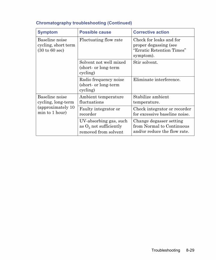
Baseline noise cycling, short term (30 to 60 sec)
Fluctuating flow rate Check for leaks and for proper degassing (see “Erratic Retention Times” symptom).
Solvent not well mixed (short- or long-term cycling)
Stir solvent.
Radio frequency noise (short- or long-term cycling)
Eliminate interference.
Baseline noise cycling, long-term (approximately 10 min to 1 hour)
Ambient temperature fluctuations
Stabilize ambient temperature.
Faulty integrator or recorder
Check integrator or recorder for excessive baseline noise.
UV-absorbing gas, such as O2 not sufficiently removed from solvent
Change degasser setting from Normal to Continuous and/or reduce the flow rate.
Chromatography troubleshooting (Continued)
Symptom Possible cause Corrective action
Troubleshooting 8-29

Baseline noise, random
Air in detector Purge detector to remove air.Solvents not properly degassed
Degas solvents.
Bubble(s) present Re-prime the solvent management system. Remove and vacuum filter solvents. Change degasser mode from Normal to Continuous.
Solvents contaminated Use fresh solvent.Column contaminated Clean/replace column.Dirty flow cell Clean flow cell. Analog output cable not properly connected between separations module and data system, recorder, or integrator
Properly connect cable.
System improperly grounded
Plug into outlet on different electrical circuit.Use power conditioner.
Recorder voltage incorrect
Set recorder to correct voltage.
Unit not cooling properly Operate unit with covers in place. Check back panel for proper clearance. Perform the Defrost Sample function (see “Defrosting the sample heater/cooler” on page 8-20).
Radio frequency noise Eliminate interference.Defective detector Troubleshoot detector.
Chromatography troubleshooting (Continued)
Symptom Possible cause Corrective action
8-30 Diagnostic Testing and Troubleshooting

Flat baseline, no peaks
No solvent flow Check flow rate.Lamp not on Use detector diagnostics to
check reference/sample energy. Zero energy indicates lamp not on.Power-on lamp. If this does not resolve the problem, replace the lamp.
Detector not zeroed Zero the detector baseline.Improper connection between detector and recorder
Check cabling between the detector and the recorder.
Incorrect wavelength Check wavelength setting.Leak in solvent path Check fittings.
Flat-topped peaks Detector not zeroed Zero the detector baseline.Incorrect recorder input voltage
Adjust recorder input voltage, or adjust detector output cable to correct position.
Sensitivity too high Select a less sensitive detection range.
Sample concentration or injection volume exceeds voltage output of detector
Decrease sample concentration or injection volume.
Chromatography troubleshooting (Continued)
Symptom Possible cause Corrective action
Troubleshooting 8-31
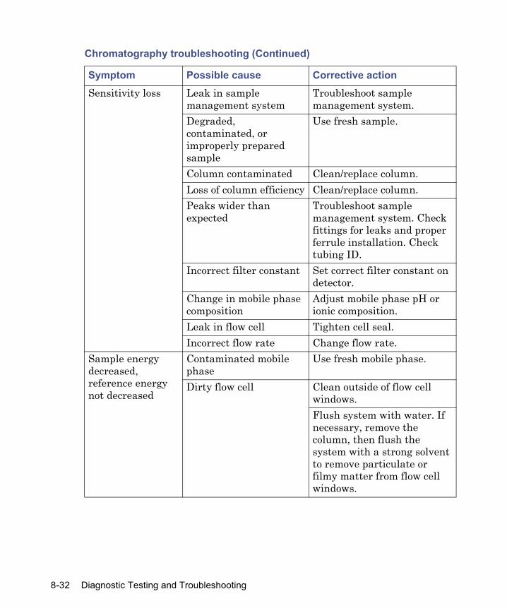
Sensitivity loss Leak in sample management system
Troubleshoot sample management system.
Degraded, contaminated, or improperly prepared sample
Use fresh sample.
Column contaminated Clean/replace column.Loss of column efficiency Clean/replace column.Peaks wider than expected
Troubleshoot sample management system. Check fittings for leaks and proper ferrule installation. Check tubing ID.
Incorrect filter constant Set correct filter constant on detector.
Change in mobile phase composition
Adjust mobile phase pH or ionic composition.
Leak in flow cell Tighten cell seal.Incorrect flow rate Change flow rate.
Sample energy decreased, reference energy not decreased
Contaminated mobile phase
Use fresh mobile phase.
Dirty flow cell Clean outside of flow cell windows.Flush system with water. If necessary, remove the column, then flush the system with a strong solvent to remove particulate or filmy matter from flow cell windows.
Chromatography troubleshooting (Continued)
Symptom Possible cause Corrective action
8-32 Diagnostic Testing and Troubleshooting
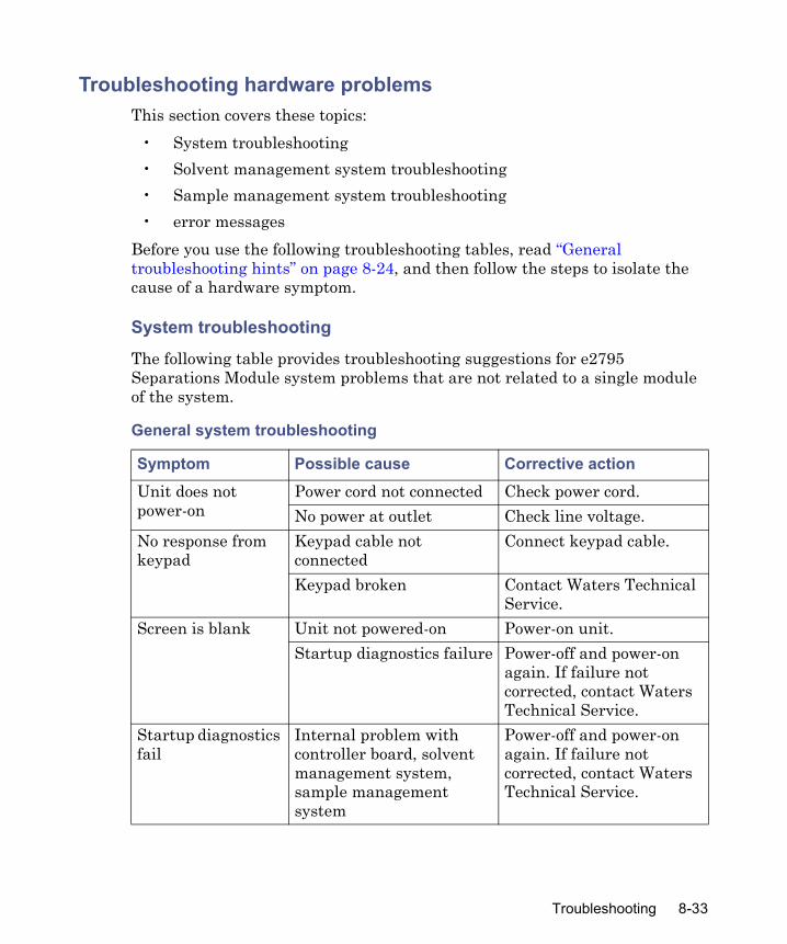
Troubleshooting hardware problems This section covers these topics:
• System troubleshooting• Solvent management system troubleshooting• Sample management system troubleshooting• error messages
Before you use the following troubleshooting tables, read “General troubleshooting hints” on page 8-24, and then follow the steps to isolate the cause of a hardware symptom.
System troubleshooting
The following table provides troubleshooting suggestions for e2795 Separations Module system problems that are not related to a single module of the system.
General system troubleshooting
Symptom Possible cause Corrective actionUnit does not power-on
Power cord not connected Check power cord.No power at outlet Check line voltage.
No response from keypad
Keypad cable not connected
Connect keypad cable.
Keypad broken Contact Waters Technical Service.
Screen is blank Unit not powered-on Power-on unit.Startup diagnostics failure Power-off and power-on
again. If failure not corrected, contact Waters Technical Service.
Startup diagnostics fail
Internal problem with controller board, solvent management system, sample management system
Power-off and power-on again. If failure not corrected, contact Waters Technical Service.
Troubleshooting 8-33

Startup failure with error message Overpressure: check in-line filter
Clogged in-line filter Clean or replace filter element
Blockage in sample management waste line
Remove blockage or replace line
Restriction between solvent and sample management systems
Remove restriction
Front panel firmware “lock up”
Firmware problem or power line problem
Power-off and power-on again. If failure is not corrected, contact Waters Technical Service.
Fans not running Unit not powered-on Power-on unit.Fan wiring or fan motor problem
Contact Waters Technical Service.
Power supply not working Contact Waters Technical Service.
Separations module not fully functional in remote configuration (IEEE-488 remote data system)
Data system not programmed to control all separations module functions
Separations module not configured for control by remote data system
Disconnect the separations module from the remote data system, and then run the unit in a standalone mode to test functionality.Configure separations module for remote control operation (see “Configuring the operating mode” on page 3-25).
General system troubleshooting (Continued)
Symptom Possible cause Corrective action
8-34 Diagnostic Testing and Troubleshooting

Solvent management system troubleshooting
The following table provides troubleshooting suggestions for solvent management system problems in the separations module.
Solvent management system troubleshooting
Symptom Possible cause Corrective actionPlunger head leaks solvent
Worn plunger seals Replace plunger seals (see “Replacing the plunger seals” on page 7-9).
Worn seal-wash seals Replace seal-wash seals (see “Replacing the seal-wash assembly seals” on page 7-12).
Loose head Hand-tighten head nut.Loose inlet check valve Tighten check valve.Worn face seals Replace face seals.Seal-wash tubes not properly installed
Install tubes properly.
Troubleshooting 8-35

Erratic flow/pressure pulsations
Gas dissolved in mobile phase
Degas solvents.
Air bubble in head Prime solvent management system to remove bubble. Increase degassing time before use. Turn on bubble detect alarm in the Mobile Phase screen (see “Setting mobile phase parameter values” on page 5-8).
Dirty inlet check valves Loosen the check valve for a few strokes and determine whether it starts flowing properly. You can also try cleaning the check valves by running wet prime. Clean/replace inlet check valves (see “Replacing an inlet check valve cartridge” on page 7-16).
Prime/vent valve open or leaking
Close or rebuild prime/vent valve.
Plugged solvent reservoir diffuser
Clean or replace diffuser.
Plunger seal leaking Replace plunger seal assembly (see “Replacing the plunger seals” on page 7-9).
Solvent management system troubleshooting (Continued)
Symptom Possible cause Corrective action
8-36 Diagnostic Testing and Troubleshooting
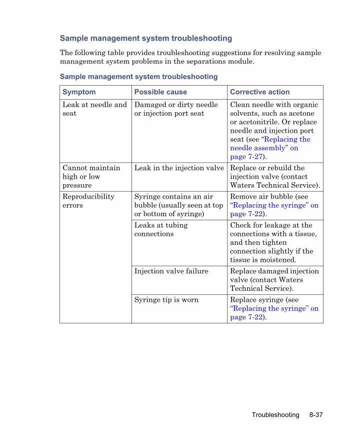
Sample management system troubleshooting
The following table provides troubleshooting suggestions for resolving sample management system problems in the separations module.
Sample management system troubleshooting
Symptom Possible cause Corrective actionLeak at needle and seat
Damaged or dirty needle or injection port seat
Clean needle with organic solvents, such as acetone or acetonitrile. Or replace needle and injection port seat (see “Replacing the needle assembly” on page 7-27).
Cannot maintain high or low pressure
Leak in the injection valve Replace or rebuild the injection valve (contact Waters Technical Service).
Reproducibility errors
Syringe contains an air bubble (usually seen at top or bottom of syringe)
Remove air bubble (see “Replacing the syringe” on page 7-22).
Leaks at tubing connections
Check for leakage at the connections with a tissue, and then tighten connection slightly if the tissue is moistened.
Injection valve failure Replace damaged injection valve (contact Waters Technical Service).
Syringe tip is worn Replace syringe (see “Replacing the syringe” on page 7-22).
Troubleshooting 8-37

Error messages
The following table lists error messages you can encounter while using the separations module and provides possible causes and/or corrective actions. Error messages that are displayed during operation of the separations module are recorded in the error log (see “Using the error log” on page 8-3).
Carrier malfunction
Plates not properly positioned
Reposition plates in compartment (see “Loading the sample plates” on page 3-38).
Plate carrier jammed Inspect plate positioner spring (see “Loading the sample plates” on page 3-38).
Plate carrier or sample compartment floor contaminated
Clean sample compartment (see “Cleaning the sample compartment and plate carrier” on page 7-46).
Separations module error messages
Error message Causes/recovery actionsGeneral instrument fault Power-off, and then power-on the
separations module. If error persists, contact Waters Technical Service.
Initialization fault Power-off, and then power-on the separations module. If error persists, contact Waters Technical Service.
General electronics fault Power-off, and then power-on the separations module. If error persists, contact Waters Technical Service.
System over pressure Clogged in-line filter or columnSystem under pressure System leak
Sample management system troubleshooting (Continued)
Symptom Possible cause Corrective action
8-38 Diagnostic Testing and Troubleshooting
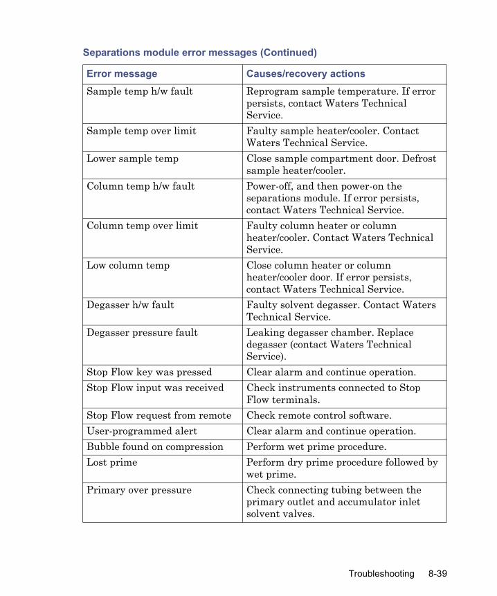
Sample temp h/w fault Reprogram sample temperature. If error persists, contact Waters Technical Service.
Sample temp over limit Faulty sample heater/cooler. Contact Waters Technical Service.
Lower sample temp Close sample compartment door. Defrost sample heater/cooler.
Column temp h/w fault Power-off, and then power-on the separations module. If error persists, contact Waters Technical Service.
Column temp over limit Faulty column heater or column heater/cooler. Contact Waters Technical Service.
Low column temp Close column heater or column heater/cooler door. If error persists, contact Waters Technical Service.
Degasser h/w fault Faulty solvent degasser. Contact Waters Technical Service.
Degasser pressure fault Leaking degasser chamber. Replace degasser (contact Waters Technical Service).
Stop Flow key was pressed Clear alarm and continue operation.Stop Flow input was received Check instruments connected to Stop
Flow terminals.Stop Flow request from remote Check remote control software.User-programmed alert Clear alarm and continue operation.Bubble found on compression Perform wet prime procedure.Lost prime Perform dry prime procedure followed by
wet prime.Primary over pressure Check connecting tubing between the
primary outlet and accumulator inlet solvent valves.
Separations module error messages (Continued)
Error message Causes/recovery actions
Troubleshooting 8-39
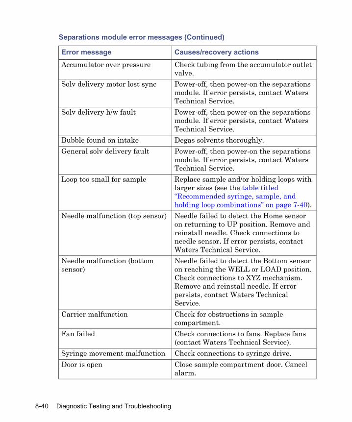
Accumulator over pressure Check tubing from the accumulator outlet valve.
Solv delivery motor lost sync Power-off, then power-on the separations module. If error persists, contact Waters Technical Service.
Solv delivery h/w fault Power-off, then power-on the separations module. If error persists, contact Waters Technical Service.
Bubble found on intake Degas solvents thoroughly.General solv delivery fault Power-off, then power-on the separations
module. If error persists, contact Waters Technical Service.
Loop too small for sample Replace sample and/or holding loops with larger sizes (see the table titled “Recommended syringe, sample, and holding loop combinations” on page 7-40).
Needle malfunction (top sensor) Needle failed to detect the Home sensor on returning to UP position. Remove and reinstall needle. Check connections to needle sensor. If error persists, contact Waters Technical Service.
Needle malfunction (bottom sensor)
Needle failed to detect the Bottom sensor on reaching the WELL or LOAD position. Check connections to XYZ mechanism. Remove and reinstall needle. If error persists, contact Waters Technical Service.
Carrier malfunction Check for obstructions in sample compartment.
Fan failed Check connections to fans. Replace fans (contact Waters Technical Service).
Syringe movement malfunction Check connections to syringe drive.Door is open Close sample compartment door. Cancel
alarm.
Separations module error messages (Continued)
Error message Causes/recovery actions
8-40 Diagnostic Testing and Troubleshooting

Needle is busy Close sample compartment door.Needle malfunction Can occur when the needle detects the
bottom sensor while moving. Also, may also occur if Home sensor is detected when the needle is not at the HOME position. Check connections to XYZ mechanism. Ensure plate configurations are correct for plate type and well bottom.
Column heater door open Close column heater door. Clear alarm.System transducer range Power-off, then power-on the separations
module (to zero transducer).Primary transducer range Power-off, then power-on the separations
module (to zero transducer).GPV h/w fault Check fluidic and electrical connections to
the GPV. Replace GPV (contact Waters Technical Service).
Auto Shutdown invoked Clear alarm. Continue operation.Degasser high leak rate Leaking degasser chamber. Replace
chamber (contact Waters Technical Service).
Overpressure: check in-line filter
Clogged in-line filter. Clean or replace.
Injection parameters incorrect The location field in the injection is incorrect for the plate configuration specified. Reconfigure the plate.
Carrier lockpin movement failed Lockpin Home sensor not detected at the HOME position. Check connections to the lockpin motor.
Inject valve movement failure Position sensors do not match the intended position. Check connections to inject valve.
Plate parameters are incorrect Specified plate dimensions extend beyond the range of needle XY movement. Reconfigure plate.
Separations module error messages (Continued)
Error message Causes/recovery actions
Troubleshooting 8-41
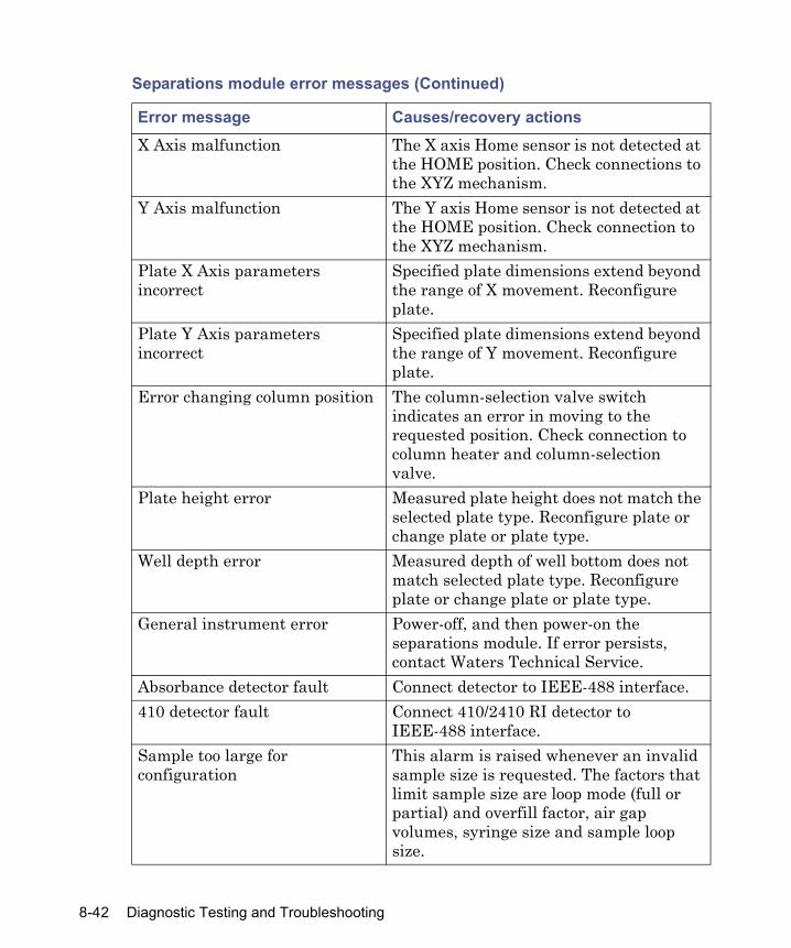
X Axis malfunction The X axis Home sensor is not detected at the HOME position. Check connections to the XYZ mechanism.
Y Axis malfunction The Y axis Home sensor is not detected at the HOME position. Check connection to the XYZ mechanism.
Plate X Axis parameters incorrect
Specified plate dimensions extend beyond the range of X movement. Reconfigure plate.
Plate Y Axis parameters incorrect
Specified plate dimensions extend beyond the range of Y movement. Reconfigure plate.
Error changing column position The column-selection valve switch indicates an error in moving to the requested position. Check connection to column heater and column-selection valve.
Plate height error Measured plate height does not match the selected plate type. Reconfigure plate or change plate or plate type.
Well depth error Measured depth of well bottom does not match selected plate type. Reconfigure plate or change plate or plate type.
General instrument error Power-off, and then power-on the separations module. If error persists, contact Waters Technical Service.
Absorbance detector fault Connect detector to IEEE-488 interface.410 detector fault Connect 410/2410 RI detector to
IEEE-488 interface.Sample too large for configuration
This alarm is raised whenever an invalid sample size is requested. The factors that limit sample size are loop mode (full or partial) and overfill factor, air gap volumes, syringe size and sample loop size.
Separations module error messages (Continued)
Error message Causes/recovery actions
8-42 Diagnostic Testing and Troubleshooting
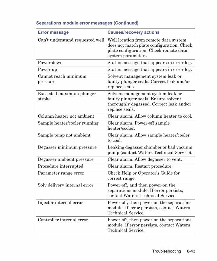
Can’t understand requested well Well location from remote data system does not match plate configuration. Check plate configuration. Check remote data system parameters.
Power down Status message that appears in error log.Power up Status message that appears in error log.Cannot reach minimum pressure
Solvent management system leak or faulty plunger seals. Correct leak and/or replace seals.
Exceeded maximum plunger stroke
Solvent management system leak or faulty plunger seals. Ensure solvent thoroughly degassed. Correct leak and/or replace seals.
Column heater not ambient Clear alarm. Allow column heater to cool.Sample heater/cooler running Clear alarm. Power-off sample
heater/cooler.Sample temp not ambient Clear alarm. Allow sample heater/cooler
to cool.Degasser minimum pressure Leaking degasser chamber or bad vacuum
pump (contact Waters Technical Service).Degasser ambient pressure Clear alarm. Allow degasser to vent.Procedure interrupted Clear alarm. Restart procedure.Parameter range error Check Help or Operator’s Guide for
correct range.Solv delivery internal error Power-off, and then power-on the
separations module. If error persists, contact Waters Technical Service.
Injector internal error Power-off, then power-on the separations module. If error persists, contact Waters Technical Service.
Controller internal error Power-off, then power-on the separations module. If error persists, contact Waters Technical Service.
Separations module error messages (Continued)
Error message Causes/recovery actions
Troubleshooting 8-43

Seal wash internal error Power-off, then power-on the separations module. If error persists, contact Waters Technical Service.
Default separation method created
This message in the error log indicated that the default method had been corrupted or otherwise lost. However, in situations when a Clear-8 or Clear-0 power-up key sequence is used to erase flash memory, the log entry is normal.
System Prep requires a degasser This alarm occurs if the user attempts to run a new System Prep function that has no Alliance degasser installed (or failed to detect).
Must degas solvents for System Prep
This alarm occurs when the System Prep function is invoked with the degasser is Off. The degasser will be turned on automatically.
Top and bottom needle sensors active
This diagnostic alarm occurs in a particular failure mode when both the top and bottom needle sensors fail to activate.
Exclamation point (!) replaces the method or sample set icon
Corrupted or invalid separations methods or sample sets will be identified with an exclamation point (!) in place of either the separations method or sample set icon. Methods marked with an exclamation point are not available for use. See Fatal error.
Separations module error messages (Continued)
Error message Causes/recovery actions
8-44 Diagnostic Testing and Troubleshooting

A Safety Advisories
Waters instruments display hazard symbols designed to alert you to the hidden dangers of operating and maintaining the instruments. Their corresponding user guides also include the hazard symbols, with accompanying text statements describing the hazards and telling you how to avoid them. This appendix presents all the safety symbols and statements that apply to the entire line of Waters products.
Contents
Topic PageWarning symbols A-2Caution symbol A-5Warnings that apply to all Waters instruments A-6Electrical and handling symbols A-13
A-1

Warning symbols
Warning symbols alert you to the risk of death, injury, or seriously adverse physiological reactions associated with an instrument’s use or misuse. Heed all warnings when you install, repair, and operate Waters instruments. Waters assumes no liability for the failure of those who install, repair, or operate its instruments to comply with any safety precaution.
Task-specific hazard warningsThe following warning symbols alert you to risks that can arise when you operate or maintain an instrument or instrument component. Such risks include burn injuries, electric shocks, ultraviolet radiation exposures, and others. When the following symbols appear in a manual’s narratives or procedures, their accompanying text identifies the specific risk and explains how to avoid it.
Warning: (General risk of danger. When this symbol appears on an instrument, consult the instrument’s user documentation for important safety-related information before you use the instrument.)
Warning: (Risk of burn injury from contacting hot surfaces.)
Warning: (Risk of electric shock.)
Warning: (Risk of fire.)
Warning: (Risk of sharp-point puncture injury.)
Warning: (Risk of hand crush injury.)
Warning: (Risk of exposure to ultraviolet radiation.)
Warning: (Risk of contacting corrosive substances.)
Warning: (Risk of exposure to a toxic substance.)
Warning: (Risk of personal exposure to laser radiation.)
A-2 Safety Advisories

Specific warningsThe following warnings can appear in the user manuals of particular instruments and on labels affixed to them or their component parts.
Burst warning
This warning applies to Waters instruments fitted with nonmetallic tubing.
Warning: (Risk of exposure to biological agents that can pose a serious health threat.)
Warning: (Risk of tipping.)
Warning: (Risk of explosion.)
Warning: (Risk of eye injury.)
Warning: Pressurized nonmetallic, or polymer, tubing can burst. Observe these precautions when working around such tubing:• Wear eye protection.• Extinguish all nearby flames.• Do not use tubing that is, or has been, stressed or kinked.• Do not expose nonmetallic tubing to incompatible compounds like
tetrahydrofuran (THF) and nitric or sulfuric acids.• Be aware that some compounds, like methylene chloride and
dimethyl sulfoxide, can cause nonmetallic tubing to swell, which significantly reduces the pressure at which the tubing can rupture.
Warning symbols A-3
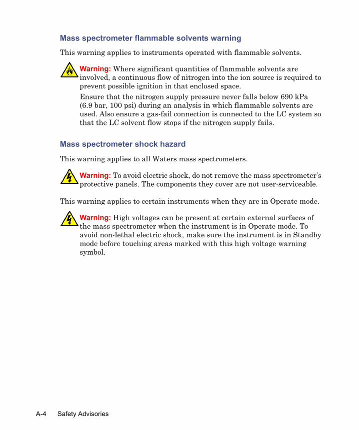
Mass spectrometer flammable solvents warning
This warning applies to instruments operated with flammable solvents.
Mass spectrometer shock hazard
This warning applies to all Waters mass spectrometers.
This warning applies to certain instruments when they are in Operate mode.
Warning: Where significant quantities of flammable solvents are involved, a continuous flow of nitrogen into the ion source is required to prevent possible ignition in that enclosed space. Ensure that the nitrogen supply pressure never falls below 690 kPa (6.9 bar, 100 psi) during an analysis in which flammable solvents are used. Also ensure a gas-fail connection is connected to the LC system so that the LC solvent flow stops if the nitrogen supply fails.
Warning: To avoid electric shock, do not remove the mass spectrometer’s protective panels. The components they cover are not user-serviceable.
Warning: High voltages can be present at certain external surfaces of the mass spectrometer when the instrument is in Operate mode. To avoid non-lethal electric shock, make sure the instrument is in Standby mode before touching areas marked with this high voltage warning symbol.
A-4 Safety Advisories
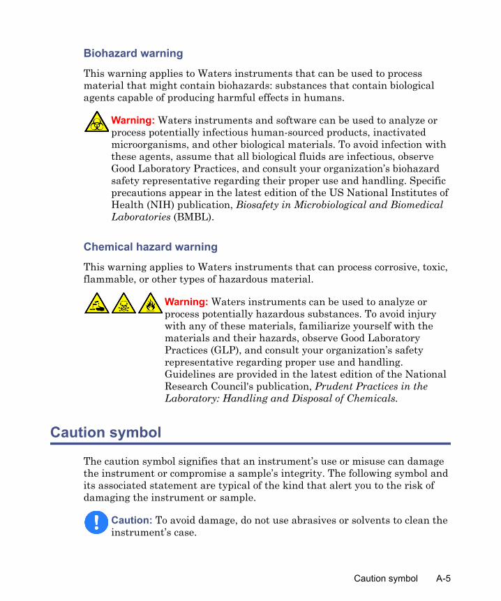
Biohazard warning
This warning applies to Waters instruments that can be used to process material that might contain biohazards: substances that contain biological agents capable of producing harmful effects in humans.
Chemical hazard warning
This warning applies to Waters instruments that can process corrosive, toxic, flammable, or other types of hazardous material.
Caution symbol
The caution symbol signifies that an instrument’s use or misuse can damage the instrument or compromise a sample’s integrity. The following symbol and its associated statement are typical of the kind that alert you to the risk of damaging the instrument or sample.
Warning: Waters instruments and software can be used to analyze or process potentially infectious human-sourced products, inactivated microorganisms, and other biological materials. To avoid infection with these agents, assume that all biological fluids are infectious, observe Good Laboratory Practices, and consult your organization’s biohazard safety representative regarding their proper use and handling. Specific precautions appear in the latest edition of the US National Institutes of Health (NIH) publication, Biosafety in Microbiological and Biomedical Laboratories (BMBL).
Warning: Waters instruments can be used to analyze or process potentially hazardous substances. To avoid injury with any of these materials, familiarize yourself with the materials and their hazards, observe Good Laboratory Practices (GLP), and consult your organization’s safety representative regarding proper use and handling. Guidelines are provided in the latest edition of the National Research Council's publication, Prudent Practices in the Laboratory: Handling and Disposal of Chemicals.
Caution: To avoid damage, do not use abrasives or solvents to clean the instrument’s case.
Caution symbol A-5
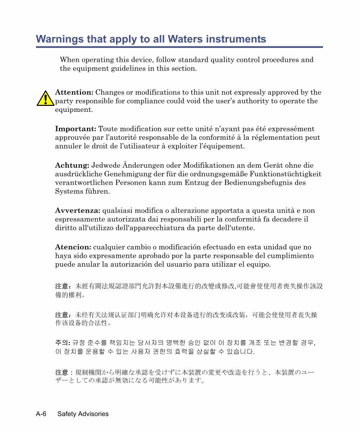
Warnings that apply to all Waters instruments
When operating this device, follow standard quality control procedures and the equipment guidelines in this section.
Attention: Changes or modifications to this unit not expressly approved by the party responsible for compliance could void the user’s authority to operate the equipment.
Important: Toute modification sur cette unité n’ayant pas été expressément approuvée par l’autorité responsable de la conformité à la réglementation peut annuler le droit de l’utilisateur à exploiter l’équipement.
Achtung: Jedwede Änderungen oder Modifikationen an dem Gerät ohne die ausdrückliche Genehmigung der für die ordnungsgemäße Funktionstüchtigkeit verantwortlichen Personen kann zum Entzug der Bedienungsbefugnis des Systems führen.
Avvertenza: qualsiasi modifica o alterazione apportata a questa unità e non espressamente autorizzata dai responsabili per la conformità fa decadere il diritto all'utilizzo dell'apparecchiatura da parte dell'utente.
Atencion: cualquier cambio o modificación efectuado en esta unidad que no haya sido expresamente aprobado por la parte responsable del cumplimiento puede anular la autorización del usuario para utilizar el equipo.
注意:未經有關法規認證部門允許對本設備進行的改變或修改,可能會使使用者喪失操作該設
備的權利。
注意:未经有关法规认证部门明确允许对本设备进行的改变或改装,可能会使使用者丧失操作该设备的合法性。
주의: 규정 준수를 책임지는 당사자의 명백한 승인 없이 이 장치를 개조 또는 변경할 경우, 이 장치를 운용할 수 있는 사용자 권한의 효력을 상실할 수 있습니다.
注意:規制機関から明確な承認を受けずに本装置の変更や改造を行うと、本装置のユーザーとしての承認が無効になる可能性があります。
A-6 Safety Advisories

Warning: Use caution when working with any polymer tubing under pressure:• Always wear eye protection when near pressurized polymer tubing.• Extinguish all nearby flames.• Do not use tubing that has been severely stressed or kinked.• Do not use nonmetallic tubing with tetrahydrofuran (THF) or concentrated
nitric or sulfuric acids.• Be aware that methylene chloride and dimethyl sulfoxide cause nonmetallic
tubing to swell, which greatly reduces the rupture pressure of the tubing.Attention: Manipulez les tubes en polymère sous pression avec precaution:• Portez systématiquement des lunettes de protection lorsque vous vous
trouvez à proximité de tubes en polymère pressurisés.• Eteignez toute flamme se trouvant à proximité de l’instrument.• Evitez d'utiliser des tubes sévèrement déformés ou endommagés.• Evitez d'utiliser des tubes non métalliques avec du tétrahydrofurane (THF)
ou de l'acide sulfurique ou nitrique concentré.• Sachez que le chlorure de méthylène et le diméthylesulfoxyde entraînent le
gonflement des tuyaux non métalliques, ce qui réduit considérablement leur pression de rupture.
Vorsicht: Bei der Arbeit mit Polymerschläuchen unter Druck ist besondere Vorsicht angebracht:• In der Nähe von unter Druck stehenden Polymerschläuchen stets
Schutzbrille tragen.• Alle offenen Flammen in der Nähe löschen.• Keine Schläuche verwenden, die stark geknickt oder überbeansprucht sind.• Nichtmetallische Schläuche nicht für Tetrahydrofuran (THF) oder
konzentrierte Salpeter- oder Schwefelsäure verwenden.• Durch Methylenchlorid und Dimethylsulfoxid können nichtmetallische
Schläuche quellen; dadurch wird der Berstdruck des Schlauches erheblich reduziert.
Warnings that apply to all Waters instruments A-7

Attenzione: fare attenzione quando si utilizzano tubi in materiale polimerico sotto pressione:• Indossare sempre occhiali da lavoro protettivi nei pressi di tubi di polimero
pressurizzati.• Spegnere tutte le fiamme vive nell'ambiente circostante.• Non utilizzare tubi eccessivamente logorati o piegati.• Non utilizzare tubi non metallici con tetraidrofurano (THF) o acido solforico
o nitrico concentrati.• Tenere presente che il cloruro di metilene e il dimetilsolfossido provocano
rigonfiamenti nei tubi non metallici, riducendo notevolmente la pressione di rottura dei tubi stessi.
Advertencia: se recomienda precaución cuando se trabaje con tubos de polímero sometidos a presión:• El usuario deberá protegerse siempre los ojos cuando trabaje cerca de tubos
de polímero sometidos a presión.• Si hubiera alguna llama las proximidades.• No se debe trabajar con tubos que se hayan doblado o sometido a altas
presiones.• Es necesario utilizar tubos de metal cuando se trabaje con tetrahidrofurano
(THF) o ácidos nítrico o sulfúrico concentrados.• Hay que tener en cuenta que el cloruro de metileno y el sulfóxido de dimetilo
dilatan los tubos no metálicos, lo que reduce la presión de ruptura de los tubos.
警告:當在有壓力的情況下使用聚合物管線時,小心注意以下幾點。
• 當接近有壓力的聚合物管線時一定要戴防護眼鏡。
• 熄滅附近所有的火焰。
• 不要使用已經被壓癟或嚴重彎曲管線。
• 不要在非金屬管線中使用四氫呋喃或濃硝酸或濃硫酸。
• 要了解使用二氯甲烷及二甲基亞楓會導致非金屬管線膨脹,大大降低管線的耐壓能力。
A-8 Safety Advisories
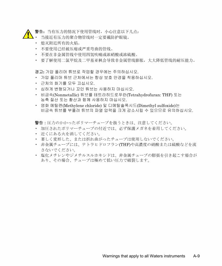
警告:当有压力的情况下使用管线时,小心注意以下几点:
• 当接近有压力的聚合物管线时一定要戴防护眼镜。
• 熄灭附近所有的火焰。
• 不要使用已经被压瘪或严重弯曲的管线。
• 不要在非金属管线中使用四氢呋喃或浓硝酸或浓硫酸。
• 要了解使用二氯甲烷及二甲基亚枫会导致非金属管线膨胀,大大降低管线的耐压能力。
경고: 가압 폴리머 튜브로 작업할 경우에는 주의하십시오.• 가압 폴리머 튜브 근처에서는 항상 보호 안경을 착용하십시오.• 근처의 화기를 모두 끄십시오.• 심하게 변형되거나 꼬인 튜브는 사용하지 마십시오.• 비금속(Nonmetallic) 튜브를 테트라히드로푸란(Tetrahydrofuran: THF) 또는 농축 질산 또는 황산과 함께 사용하지 마십시오.
• 염화 메틸렌(Methylene chloride) 및 디메틸술폭시드(Dimethyl sulfoxide)는 비금속 튜브를 부풀려 튜브의 파열 압력을 크게 감소시킬 수 있으므로 유의하십시오.
警告:圧力のかかったポリマーチューブを扱うときは、注意してください。
• 加圧されたポリマーチューブの付近では、必ず保護メガネを着用してください。
• 近くにある火を消してください。
• 著しく変形した、または折れ曲がったチューブは使用しないでください。
• 非金属チューブには、テトラヒドロフラン(THF)や高濃度の硝酸または硫酸などを流
さないでください。
• 塩化メチレンやジメチルスルホキシドは、非金属チューブの膨張を引き起こす場合があり、その場合、チューブは極めて低い圧力で破裂します。
Warnings that apply to all Waters instruments A-9

Warning: The user shall be made aware that if the equipment is used in a manner not specified by the manufacturer, the protection provided by the equipment may be impaired.
Attention: L’utilisateur doit être informé que si le matériel est utilisé d’une façon non spécifiée par le fabricant, la protection assurée par le matériel risque d’être défectueuses.
Vorsicht: Der Benutzer wird darauf aufmerksam gemacht, dass bei unsachgemäßer Verwenddung des Gerätes die eingebauten Sicherheitseinrichtungen unter Umständen nicht ordnungsgemäß funktionieren.
Attenzione: si rende noto all'utente che l'eventuale utilizzo dell'apparecchiatura secondo modalità non previste dal produttore può compromettere la protezione offerta dall'apparecchiatura.
Advertencia: el usuario deberá saber que si el equipo se utiliza de forma distinta a la especificada por el fabricante, las medidas de protección del equipo podrían ser insuficientes.
警告:使用者必須非常清楚如果設備不是按照製造廠商指定的方式使用,那麼該設備所提供的保護將被消弱。
警告:使用者必须非常清楚如果设备不是按照制造厂商指定的方式使用,那么该设备所提供的保护将被削弱。
경고: 제조업체가 명시하지 않은 방식으로 장비를 사용할 경우 장비가 제공하는 보호 수단이 제대로 작동하지 않을 수 있다는 점을 사용자에게 반드시 인식시켜야 합니다.
警告: ユーザーは、製造元により指定されていない方法で機器を使用すると、機器が提供している保証が無効になる可能性があることに注意して下さい。
A-10 Safety Advisories
[Fuse protection varies with instrument type, so you must consider which of these three fusing conditions apply to your instrument:
• Condition 1: Instrument not equipped with user-replaceable fuses – When an instrument’s fuses are not user-replaceable, delete from this appendix all warnings addressing fuse replacement. Also delete any “Replacing fuses” section from the Maintenance Procedures chapter.
• Condition 2: Instrument equipped with user-replaceable fuses, and the fuse information appears on the instrument – When an instrument’s fuses are user-replaceable, and fuse types and ratings appear on the instrument, include the Version 1 warning set, below.]
Warnings that apply to all Waters instruments A-11

Warning: To protect against fire, replace fuses with those of the type and rating printed on panels adjacent to instrument fuse covers.Attention: pour éviter tout risque d'incendie, remplacez toujours les fusibles par d'autres du type et de la puissance indiqués sur le panneau à proximité du couvercle de la boite à fusible de l'instrument.Vorsicht: Zum Schutz gegen Feuer die Sicherungen nur mit Sicherungen ersetzen, deren Typ und Nennwert auf den Tafeln neben den Sicherungsabdeckungen des Geräts gedruckt sind.Attenzione: per garantire protezione contro gli incendi, sostituire i fusibili con altri dello stesso tipo aventi le caratteristiche indicate sui pannelli adiacenti alla copertura fusibili dello strumento.Advertencia: Para evitar incendios, sustituir los fusibles por aquellos del tipo y características impresos en los paneles adyacentes a las cubiertas de los fusibles del instrumento.
警告 : 為了避免火災,更換保險絲時,請使用與儀器保險絲蓋旁面板上所印刷之相同類型與規格的保險絲。
警告 : 为了避免火灾,应更换与仪器保险丝盖旁边面板上印刷的类型和规格相同的保险丝。
경고: 화재의 위험을 막으려면 기기 퓨즈 커버에 가까운 패널에 인쇄된 것과 동일한 타입 및 정격의 제품으로 퓨즈를 교체하십시오.
警告 : 火災予防のために、ヒューズ交換では機器ヒューズカバー脇のパネルに記載されているタイプおよび定格のヒューズをご使用ください。
A-12 Safety Advisories

Electrical and handling symbols
Electrical symbolsThese can appear in instrument user manuals and on the instrument’s front or rear panels.
Electrical power on
Electrical power off
Standby
Direct current
Alternating current
Protective conductor terminal
Frame, or chassis, terminal
Fuse
Recycle symbol: Do not dispose in municipal waste.
Electrical and handling symbols A-13

Handling symbolsThese handling symbols and their associated text can appear on labels affixed to the outer packaging of Waters instrument and component shipments.
Keep upright!
Keep dry!
Fragile!
Use no hooks!
A-14 Safety Advisories

B Specifications
Contents
Topic PagePhysical specifications B-2Environmental specifications B-2Electrical specifications B-3Solvent management specifications B-3Sample management specifications B-5Instrument control and communication specifications B-6
B-1

Physical specifications
Environmental specifications
Physical specifications
Item SpecificationHeightDeptha
Widthb
Weightc
a. Includes column heater or column heater/cooler.b. Includes sample heater/cooler.c. Includes sample heater/cooler and column heater or column heater/cooler.
57 cm (22.5 in.)60 cm (25.5 in.)58 cm (23 in.)62 kg (136 lb.)
Wetted Surface Materials 316 stainless steel, ruby, sapphire, MP35N, PEEK, PPS, UHMWPE, Tefzel® (ETFE), Teflon® (FEP and PTFE), Teflon AF®, Fluoroloy G, Fluoroloy-08R
Environmental specifications
Item SpecificationOperating Temperature 4 to 40 °CRelative Humidity 20 to 80%, noncondensingAcoustic Noise <65 dB(A)Solvent Compatibility (see Appendix D)
Solvents consistent with materials of construction. Salts and buffers can reduce seal life, especially at pressures in excess of 3000 psi.
B-2 Specifications

Electrical specifications
Solvent management specifications
Electrical specifications
Item SpecificationLine Voltage 85 to 264 VACFrequency 47 to 63 Hz
Solvent management system specifications
Item SpecificationNumber of Solvents One to fourSolvent Conditioning Vacuum degas, four solvents plus purge
solventTypical Operating Flow Rate Range
0.050 to 5.000 mL/min in 0.001-mL/min increments
Programmable Flow Rate Range 0.000 and 0.010 to 10.000 mL/min in 0.001-mL/min increments
Compressibility Compensation Automatic and continuousSystem Delay Volume < 400 µL, independent of backpressure,
1 mL/minPlunger Seal Wash Integral, active, programmableGradient Profiles Eleven (11) gradient curves [including
linear, step (2 curves), concave (4 curves), and convex (4 curves)]
Dry Prime/Wet Prime Automatic, front panel controlFlow Ramping Time (0.01 to 30.00 min in 0.01-min
increments) to reach maximum flow rateMaximum Operating Pressure 5000 psi (345 bar) at 0.010 to
3.000 mL/min; programmable upper and lower limits
Composition Range 0.0 to 100.0% in 0.1% increments
Electrical specifications B-3

Composition Accuracy ± 0.5% absolute, independent of back-pressure (proportioning valve pair test [degassed methanol:methanol/propylpa-raben, 2 mL/min, 257 nm])
Composition Precision ≤ 0.15% RSD or ≤ 0.02 min SD, which-ever is greater, based on retention time. (Degassed 60% methanol:40% water Dial-a-Mix, 1 mL/min, six replicates, phenone mix, 257 nm)
Flow Precision ≤ 0.075% RSD or ≤ 0.02 min SD, which-ever is greater, based on retention time (N = 6) or volumetric measures (0.200 to 5.000 mL/min), isocratic premix
Flow Accuracy ± 1% or 10 µL/min, whichever is greater, (0.200 to 5.000 mL/ min), degassed meth-anol, at 600 psi backpressure
Solvent management system specifications (Continued)
Item Specification
B-4 Specifications

Sample management specifications
Sample management system specifications
Item SpecificationNumber of Sample Plates Total of four plates:
• Microtiter plate – 96- or 384-well• Vial plate – 2.0-mL vial (48)• Tube plate – 0.5-mL microcentrifuge
tube (48) or 1.5-mL microcentrifuge tube (24)
• Open access plate – 2.0-mL vial (24 or 48)
Sample Temperature Control 4 to 40 °C, programmable in 1 °C increments
Maximum Sample Capacity 1536 in four 384-well platesNumber of Sample Injections 1 to 99 injections per sampleSample Delivery Precision < 0.3% RSD, full loop 50 µL. (Default
wash/purge conditions, degassed 60% methanol:40% water Dial-a-Mix, 1 mL/min, six replicates, paraben mix, 257 nm)
Injector Linearity (partial loop) > 0.999% correlation, 5 to 20 µL, partial fill in 50-µL loop, 3-µL pre- and post-sample air gaps (Default wash/purge conditions, degassed 60% methanol:40% water Dial-a-Mix, 1 mL/min, six replicates, paraben mix, 257 nm)
Needle Wash Solvents Two: wash (strong solvent) and purge (sample-compatible) solvent
Sample management specifications B-5

Instrument control and communication specifications
Sample carryovera < 0.01% (based on the following chro-matographic conditions): • Column – XBridge C18, 4.6 × 50 mm,
3.5 µm• Mobile Phase – 70% Water/30% Meth-
anol• Needle Wash – 100% Methanol• Challenge Sample – 4.0 mg/mL caf-
feine (in mobile phase)• Carryover Standard – 0.4 mg/mL caf-
feine (in mobile phase)• Injection Volume (all) – 5.0 µL
a. Sample carryover test description – Setup: Four vials (#1 = Pre-blank = mobile phase, #2 = Carryover standard, #3 = Challenge sample, #4 = Post-blank = mobile phase). Procedure: 2 injections of #1, then 3 injections of #2, then 1 injection of #3, and finally, 3 injections of #4. Test result: Percent carryover is determined by comparison of the (#4) post-blank injections to the (#2) carryover standard.
Instrument control and communication specifications
Item SpecificationParallel Sample Processing
User-programmable next-sample aspiration and loop fill, column equilibration, just-in-time gradient delivery
Advanced Operations Auto addition, sample pooling, open access, priority samples
Column heater (optional)
20 ° (5 ° above ambient) to 65 °C, in 1 ° increments
Column heater/cooler (optional)
4 ° (15 ° below ambient) to 65 °C, in 1 ° increments
Column Selection 3- or 6-column select valve (optional)Ethernet interface Communication with remote control system, such
as Empower 2
Sample management system specifications (Continued)
Item Specification
B-6 Specifications
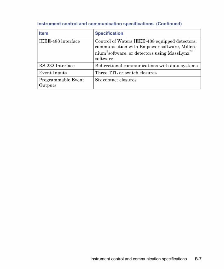
IEEE-488 interface Control of Waters IEEE-488 equipped detectors; communication with Empower software, Millen-nium®software, or detectors using MassLynx™ software
RS-232 Interface Bidirectional communications with data systemsEvent Inputs Three TTL or switch closuresProgrammable Event Outputs
Six contact closures
Instrument control and communication specifications (Continued)
Item Specification
Instrument control and communication specifications B-7

B-8 Specifications

C Spare Parts
Notes:• Parts not listed in this appendix are not recommended for customer
replacement.• For a comprehensive catalog of spare parts, see the Waters Quality
Parts Locator on the Waters Web site’s Services & Support page.
Contents
Topic PageSolvent management system spare parts C-2Sample management system spare parts C-3e2795 separations module spare parts C-4Recommended plate options C-5
C-1
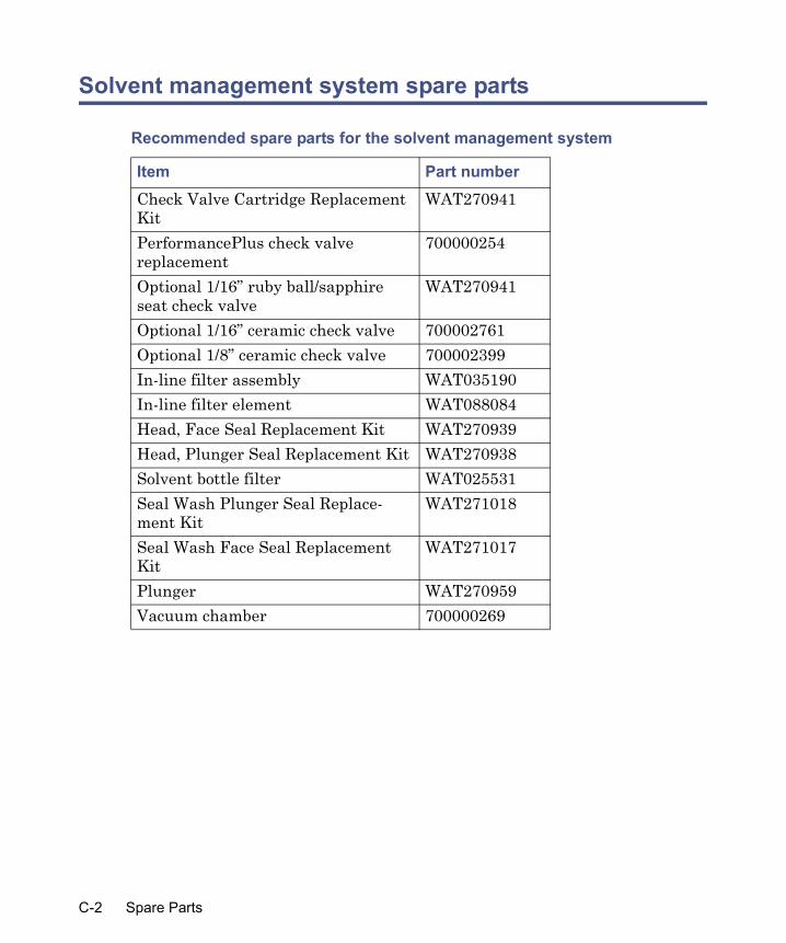
Solvent management system spare parts
Recommended spare parts for the solvent management system
Item Part numberCheck Valve Cartridge Replacement Kit
WAT270941
PerformancePlus check valve replacement
700000254
Optional 1/16” ruby ball/sapphire seat check valve
WAT270941
Optional 1/16” ceramic check valve 700002761Optional 1/8” ceramic check valve 700002399In-line filter assembly WAT035190In-line filter element WAT088084Head, Face Seal Replacement Kit WAT270939Head, Plunger Seal Replacement Kit WAT270938Solvent bottle filter WAT025531Seal Wash Plunger Seal Replace-ment Kit
WAT271018
Seal Wash Face Seal Replacement Kit
WAT271017
Plunger WAT270959Vacuum chamber 700000269
C-2 Spare Parts

Sample management system spare parts
Recommended spare parts for the sample management system
Item Part numberSyringe:100-µL250-µL500-µL (standard)1000-µL2500-µL
700000564WAT073109700000565700000611WAT077342
Sample loop:5-µL20-µL50-µL (standard)100-µL500-µL2000-µL
700000558700000559700000560700000561700000562700000563
Holding loop:128-µL500-µL3000-µL
700000555700000556700000557
Injection Valve 700000380Injection Port Seat 700000384Seal, Injection Port Washer 700000385e2795 Separations Module Injection Valve Rebuild Kit
700000411
e2795 Separations Module Three-Column Select Valve Rebuild Kit
700000431
e2795 Separations Module Six-Column Select Valve Rebuild Kit
700000434
Sample management system spare parts C-3

e2795 separations module spare parts
e2795 Separations Module Two-Position Regeneration Valve Rebuild Kit
700000424
e2795 Separations Module Needle and Housing Assembly
700000388
Separations module spare parts
Item Part numberCable assembly, AC power WAT270895Cable assembly, IEEE-488, 1 m WAT087198Detector drip tray assembly WAT271040Diffuser assembly, polyethylene WAT007272Diffuser assembly, stainless steel (1) WAT025531Ethernet Switch Communications Kit 7000004123
Recommended spare parts for the sample management system (Continued)
Item Part number
C-4 Spare Parts

Recommended plate options
The following table provides important information about Waters-supplied
Caution: • To avoid damage to the needle or XYZ mechanism, do not use vial
caps less than 8.8 mm in diameter (OD).• To avoid damage to the needle or XYZ mechanism, do not use
polyethylene cap mats below 15 °C. If the sample manager is maintained above 15 °C, a polyethylene cap mat for 96 square well plates is acceptable. However, below 15 °C, the mat can become rigid and cause the plate to lift from the carrier during the injection cycle. Sample stability may also decrease. If the sample manager is maintained from 4 to 15 °C, use a PTFE or silicone cap mat (see the table on page C-6).
• To avoid clogging the injection port and needle, do not use certain adhesive sealing materials to seal vials. You can use thin (household-variety) aluminum foil to seal 96- and 384-well plates. Some heat-sealable foils are also acceptable, such as a heat-sealing apparatus (Marsh Biomedical) or the Thermowell™ Sealer for aqueous samples (Corning Costar).
• To avoid damaging the bioseparations module, Waters recommends that you consult the table on page C-6 before operating the device.
• Because their dimensions can vary, do not use the Seek Well Bottom feature with thin-bottom glass inserts (such as part number 186000349) or with the two microcentrifuge sample container plates (part numbers 405000560 and 405000772).
Recommended plate options C-5
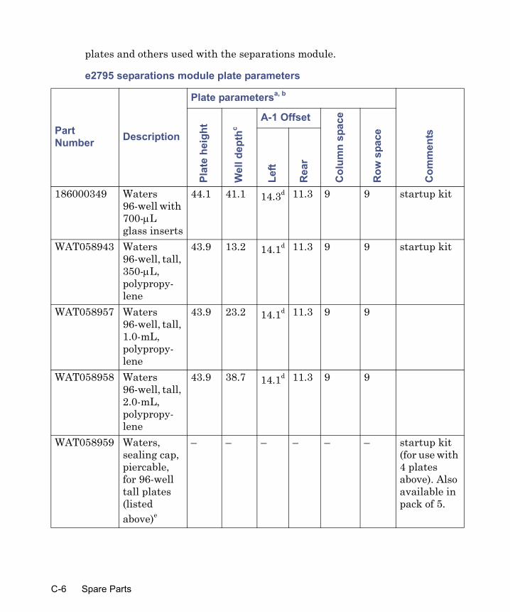
plates and others used with the separations module.
e2795 separations module plate parameters
Part Number Description
Plate parametersa, b
Com
men
ts
Plat
e he
ight
Wel
l dep
thc
A-1 Offset
Col
umn
spac
e
Row
spa
ce
Left
Rea
r
186000349 Waters 96-well with 700-μL glass inserts
44.1 41.1 14.3d 11.3 9 9 startup kit
WAT058943 Waters 96-well, tall, 350-μL, polypropy-lene
43.9 13.2 14.1d 11.3 9 9 startup kit
WAT058957 Waters 96-well, tall, 1.0-mL, polypropy-lene
43.9 23.2 14.1d 11.3 9 9
WAT058958 Waters 96-well, tall, 2.0-mL, polypropy-lene
43.9 38.7 14.1d 11.3 9 9
WAT058959 Waters, sealing cap, piercable, for 96-well tall plates (listed above)e
– – – – – – startup kit (for use with 4 plates above). Also available in pack of 5.
C-6 Spare Parts

186000857 Waters, PFTE/Sili-cone sealing capj
– – – – – –
405000562 Waters 48-position 2.0-mL vial holder
25.4 16.8f 15 8.3 14 14 startup kit
186000327 Waters 1.5-mL Max Recovery vial kit with preslit septa
– – – – – – startup kit (contains 100 vials/caps)
186000307 Waters 2-mL glass vial kit with preslit septa
– – – – – – 100 general purpose 2-mL vials/caps
405000560 Waters 24-position 1.5-mL microcentri-fuge tube holder
33.8 28.0f 14.2 11.2 19.8 19.8 Startup kit. Cap must be open and inserted in slot.
405000772 Waters 48-position0.5-mL microcentri-fuge tube holder
28.7 23.0f 12.0 9.0 14.5 13.5 Cap must be open and inserted in slot.
e2795 separations module plate parameters (Continued)
Part Number Description
Plate parametersa, b
Com
men
ts
Plat
e he
ight
Wel
l dep
thc
A-1 Offset
Col
umn
spac
e
Row
spa
ce
Left
Rea
r
Recommended plate options C-7

200000114 Waters Open Access Kit (96 vials)Waters 24-position, 2-mL vial open access plates
20.2g 10.2f 13.8 12.7 20 20 Contains 4 plates (24-position for 2-mL vials) and 100 2-mL vials with preslit septa (186000307)
200000123 Waters High-Capacity Open Access Kit (192 vials)Waters 48-position, 2-mL vial open access plates
25.4 16.8f 15 8.3 14 14 Contains 4 plates (48-position for 2-mL vials) and 100 2-mL vials with preslit septa (186000307)
– 96-well, 300-μL plate, typicala
14.3 10.0 14.1 11.3 9 9 Dimensions vary by manufac-turer
e2795 separations module plate parameters (Continued)
Part Number Description
Plate parametersa, b
Com
men
ts
Plat
e he
ight
Wel
l dep
thc
A-1 Offset
Col
umn
spac
e
Row
spa
ce
Left
Rea
r
C-8 Spare Parts

– 384-well, 80-μL plate, polysty-rene, typical h, i
14.4 10.5 12.1 9.0 4.5 4.5 Dimensions vary and are critical. Usable volume is typically 80 μL due to needle displace-ment volume.
a. Check the dimensions of all non-Waters plates before entering them in the plate parameter fields. Using incorrect dimensions can damage the needle.
b. Do not use adhesively-applied sealing films or foils. The adhesive tends to clog the injection port and needle. Heat-sealable foils are an acceptable alternative.
c. Do not use thin or flimsy plates or polymerase chain reaction (PCR) tubes. They can jam the XYZ mech-anism or be subject to penetration by the needle.
d. Use a Waters piercable sealing cap (part number WAT058959) or a Waters PTFE/silicone sealing cap (part number 1860000857) to prevent evaporation or spillage. The sealing cap also acts as a retainer for glass inserts (part number 186000349).
e. Use only sealing caps that are prescored or thinned in the needle penetration area.f. The well depth is measured with Waters vials or generic tubes in the wells. Confirm the tube measure-
ment. The minimum vial cap outside diameter is 8.8 mm.g. Use care when selecting polypropylene 384-well plates for use, because straightness of rows and col-
umns can be marginal.h. Ensure that the well contains some air to prevent a vacuum and to ensure sample draw precision.i. Measure at the “plate height” check point near the number 19 vial location.
e2795 separations module plate parameters (Continued)
Part Number Description
Plate parametersa, b
Com
men
ts
Plat
e he
ight
Wel
l dep
thc
A-1 Offset
Col
umn
spac
e
Row
spa
ce
Left
Rea
r
Recommended plate options C-9

C-10 Spare Parts

D Solvent Considerations
Contents
Topic PageSolvent quality D-2Solvent-system compatibility D-2Solvent miscibility D-5Buffered solvents D-8Solvent viscosity D-8Solvent degassing D-8Wavelength selection D-10
D-1

Solvent quality
For best results:• Use HPLC-grade solvents• Filter solvents through a 0.45-µm filter• Degas solvents.
When using unstabilized tetrahydrofuran (THF), ensure that your solvent is fresh. Previously opened bottles of THF contain peroxide contaminants that cause baseline drift.
Solvent reservoirsThe following recommendations apply to the solvent reservoirs used with the separations module:
• When using the instrument for general chromatography (i.e. reverse and/or normal phase and gel permeation [GPC]), use high-quality lab glassware made of borosilicate glass for all reservoirs (solvent, seal wash & needle wash).
• When using techniques such as ion chromatography where glass containers can contribute ionic contamination (sodium and/or chloride ions), it is acceptable to use laboratory-grade polypropylene or polyethylene containers as reservoirs.
• When using the instrument in combination with a mass spectrometric detector, refer to recommendations within the most recent version of “Controlling Contamination in UPLC/MS and HPLC/MS Systems” on the Waters’ website (www.waters.com) in the Support Library under Waters Division/Services & Support.
Solvent-system compatibility
The separations module is constructed of high-quality (316) stainless steel components that, with some minor restrictions, can be used with all solvents. This section lists the solvents that have and have not been approved for use with the separations module.
Warning: Tetrahydrofuran (THF) contaminants (peroxides) are potentially explosive if concentrated or taken to dryness.
D-2 Solvent Considerations
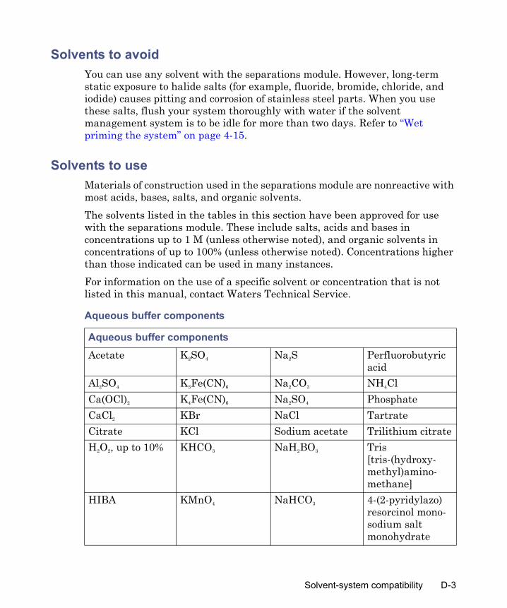
Solvents to avoidYou can use any solvent with the separations module. However, long-term static exposure to halide salts (for example, fluoride, bromide, chloride, and iodide) causes pitting and corrosion of stainless steel parts. When you use these salts, flush your system thoroughly with water if the solvent management system is to be idle for more than two days. Refer to “Wet priming the system” on page 4-15.
Solvents to useMaterials of construction used in the separations module are nonreactive with most acids, bases, salts, and organic solvents.The solvents listed in the tables in this section have been approved for use with the separations module. These include salts, acids and bases in concentrations up to 1 M (unless otherwise noted), and organic solvents in concentrations of up to 100% (unless otherwise noted). Concentrations higher than those indicated can be used in many instances.For information on the use of a specific solvent or concentration that is not listed in this manual, contact Waters Technical Service.
Aqueous buffer components
Aqueous buffer componentsAcetate K2SO4 Na2S Perfluorobutyric
acidAl2SO4 K3Fe(CN)6 Na2CO3 NH4ClCa(OCl)2 K4Fe(CN)6 Na2SO4 PhosphateCaCl2 KBr NaCl TartrateCitrate KCl Sodium acetate Trilithium citrateH2O2, up to 10% KHCO3 NaH2BO3 Tris
[tris-(hydroxy-methyl)amino-methane]
HIBA KMnO4 NaHCO3 4-(2-pyridylazo)resorcinol mono-sodium salt monohydrate
Solvent-system compatibility D-3
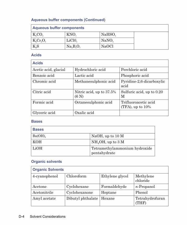
K2CO3 KNO3 NaHSO4
K2Cr2O3 LiCl04 NaNO3
K2S Na2B4O7 NaOCl
Acids
AcidsAcetic acid, glacial Hydrochloric acid Perchloric acidBenzoic acid Lactic acid Phosphoric acidChromic acid Methanesulphonic acid Pyridine-2,6-dicarboxylic
acidCitric acid Nitric acid, up to 37.5%
(6 N)Sulfuric acid, up to 0.20 M
Formic acid Octanesulphonic acid Trifluoroacetic acid (TFA), up to 10%
Glyceric acid Oxalic acid
Bases
BasesBa(OH)2 NaOH, up to 10 MKOH NH4OH, up to 3 MLiOH Tetramethylammonium hydroxide
pentahydrate
Organic solvents
Organic Solvents4-cyanophenol Chloroform Ethylene glycol Methylene
chlorideAcetone Cyclohexane Formaldehyde n-PropanolAcetonitrile Cyclohexanone Heptane PhenolAmyl acetate Dibutyl phthalate Hexane Tetrahydrofuran
(THF)
Aqueous buffer components (Continued)
Aqueous buffer components
D-4 Solvent Considerations

Solvent miscibility
Before you change solvents, refer to the following table to determine the miscibility of the solvents to be used. When you change solvents, be aware of these effects:
• Changes involving two miscible solvents can be made directly. Changes involving two solvents that are not totally miscible (for example, chloroform and water), require an intermediate solvent (such as methanol).
• Temperature affects solvent miscibility. If you are running a high-temperature application, consider the effect of the temperature on solvent solubility.
• Buffers dissolved in water can precipitate when mixed with organic solvents.
Benzaldehyde Dimethyl formamide
iso-Octane Toluene
Benzene Dimethyl sulfoxide
iso-Propanol Waters PIC® Reagents
Benzyl alcohol Ethanol Lysine hydrochloride
Xylene
Butanol Ethyl acetate MethanolCarbon tetrachloride
Ethylene dichloride
Methyl ethyl ketone
Solvent miscibility
Polarity Index Solvent Viscosity
CP, 20 °C
Boiling Point °C (@1 bar atm)
Miscibility Number (M)
λ Cutoff (nm)
–0.3 N-decane 0.92 174.1 29 –––0.4 Iso-octane 0.50 99.2 29 210 0.0 N-hexane 0.313 68.7 29 –– 0.0 Cyclohexane 0.98 80.7 28 210
Organic solvents (Continued)
Solvent miscibility D-5

1.7 Butyl ether 0.70 142.2 26 –– 1.8 Triethylamine 0.38 89.5 26 –– 2.2 Isopropyl ether 0.33 68.3 –– 220 2.3 Toluene 0.59 100.6 23 285 2.4 p-xylene 0.70 138.0 24 290 3.0 Benzene 0.65 80.1 21 280 3.3 Benzyl ether 5.33 288.3 –– –– 3.4 Methylene chloride 0.44 39.8 20 245 3.7 Ethylene chloride 0.79 83.5 20 –– 3.9 Butyl alcohol 3.00 117.7 –– –– 3.9 Butanol 3.01 177.7 15 –– 4.2 Tetrahydrofuran 0.55 66.0 17 220 4.3 Ethyl acetate 0.47 77.1 19 260 4.3 1-propanol 2.30 97.2 15 210 4.3 2-propanol 2.35 117.7 15 –– 4.4 Methyl acetate 0.45 56.3 15, 17 260 4.5 Methyl ethyl ketone 0.43 80.0 17 330 4.5 Cyclohexanone 2.24 155.7 28 210 4.5 Nitrobenzene 2.03 210.8 14, 20 –– 4.6 Benzonitrile 1.22 191.1 15, 19 –– 4.8 Dioxane 1.54 101.3 17 220 5.2 Ethanol 1.20 78.3 14 210 5.3 Pyridine 0.94 115.3 16 305 5.3 Nitroethane 0.68 114.0 –– –– 5.4 Acetone 0.32 56.3 15, 17 330 5.5 Benzyl alcohol 5.80 205.5 13 –– 5.7 Methoxyethanol 1.72 124.6 13 ––
Solvent miscibility (Continued)
Polarity Index Solvent Viscosity
CP, 20 °C
Boiling Point °C (@1 bar atm)
Miscibility Number (M)
λ Cutoff (nm)
D-6 Solvent Considerations

How to use miscibility numbers (M-numbers)Use miscibility numbers (M-numbers) to predict the miscibility of a liquid with a standard solvent (see the table, above).To predict the miscibility of two liquids, subtract the smaller M-number value from the larger M-number value.
• If the difference between the two M-numbers is 15 or less, the two liquids are miscible in all proportions at 15 °C.
• A difference of 16 indicates the solvents are miscible at temperatures between 25 and 75 °C, with 50 °C as the optimal temperature.
• If the difference is 17 or greater, the liquids are immiscible or miscible onlyabove 75 °C.
Some solvents prove immiscible with solvents at both ends of the lipophilicity scale. These solvents are assigned a dual M-number:
• The first number, always lower than 16, indicates the degree of miscibility with highly lipophilic solvents.
• The second number, always greater than 16, indicates the degree of miscibility with highly hydrophilic solvents.
• A large difference between these two M-numbers indicates a limited range of miscibility.
6.2 Acetonitrile 0.37 81.6 11, 17 190 6.2 Acetic acid 1.26 117.9 14 –– 6.4 Dimethylformamide 0.90 153.0 12 –– 6.5 Dimethylsulfoxide 2.24 189.0 9 –– 6.6 Methanol 0.60 64.7 12 210 7.3 Formamide 3.76 210.5 3 –– 9.0 Water 1.00 100.0 –– ––
Solvent miscibility (Continued)
Polarity Index Solvent Viscosity
CP, 20 °C
Boiling Point °C (@1 bar atm)
Miscibility Number (M)
λ Cutoff (nm)
Solvent miscibility D-7

For example, some fluorocarbons are immiscible with all the standard solvents and have M-numbers of 0 and 32. Two liquids with dual M-numbers are usually miscible with each other.A liquid is classified in the M-number system by testing for miscibility with a sequence of standard solvents. A correction term of 15 units is then either added or subtracted from the cutoff point for miscibility.
Buffered solvents
When using a buffer, use a good quality reagent and filter it through a 0.45-µm filter.Do not leave the buffer stored in your HPLC system. Flush all fluidic pathways with HPLC-quality water before shutting down the system and leave distilled water in the system or flush with 90% HPLC-quality water:10% methanol for shutdowns scheduled to be more than one day. Flush using a minimum of 45 mL for inline vacuum degasser-equipped units.
Solvent viscosity
Generally, viscosity is not important when you are operating with a single solvent or under low pressure. However, when you run a gradient, the viscosity changes that occur as the solvents are mixed in different proportions can result in pressure changes during the run. For example, a 1:1 mixture of water and methanol produces twice the pressure of either water or methanol alone. If the extent to which the pressure changes affect the analysis is not known, monitor the pressure during the run using the Chart Out terminal.
Solvent degassing
Mobile phase difficulties account for 70 percent or more of all liquid chromatographic problems. Using degassed solvents is important, especially at wavelengths below 220 nm. Degassing provides:
• Stable baselines and enhanced sensitivity• Reproducible retention times for eluting peaks
D-8 Solvent Considerations

• Reproducible injection volumes for quantitation• Stable pump operation
This section presents information on the solubility of gases, solvent degassing methods, and solvent degassing considerations.
Gas solubilityThe amount of gas dissolved in a given volume of liquid depends on:
• The chemical affinity of the gas for the liquid• The temperature of the liquid• The pressure applied to the liquid
Changes in the composition, temperature, or pressure of the mobile phase can lead to outgassing.
Effects of intermolecular forcesNonpolar gases (N2, O2, CO2, He) are more soluble in nonpolar solvents than in polar solvents. Generally, a gas is most soluble in a solvent whose intermolecular attractive forces are similar to those in the gas (“like dissolves like”).
Effects of temperatureTemperature affects the solubility of gases. If the heat of solution is exothermic, the solubility of the gas decreases when you heat the solvent. If the heat of solution is endothermic, the solubility increases when you heat the solvent. For example, the solubility of He in H2O decreases with an increase in temperature, but the solubility of He in benzene increases with an increase in temperature.
Effects of partial pressureThe mass of gas dissolved in a given volume of solvent is proportional to the partial pressure of the gas in the vapor phase of the solvent. If you decrease the partial pressure of the gas, the amount of that gas in solution also decreases.
Solvent degassing D-9

Vacuum degassingThe longer a solvent is exposed to a vacuum, the more dissolved gases are removed. Two factors affect the amount of time the solvent is exposed to the vacuum:
• Flow rate – At low flow rates, most of the dissolved gas is removed as the solvent passes through the vacuum chamber. At higher flow rates, lesser amounts of gas per unit volume of solvent are removed.
• Surface area of the degassing membrane – The length of the degassing membrane is fixed in each vacuum chamber. To increase the length of membrane, you can connect two or more vacuum chambers in series.
The degasser for the e2795 Separations Module is factory-installed. See “In-line vacuum degasser” on page 1-8.
Wavelength selection
The tables in this section provide UV cutoff values for:• Common solvents• Common mixed mobile phases• Chromophores
Wavelength cutoffs for common solventsThe following table shows the wavelength cutoff (the wavelength at which the absorbance of the solvent is equal to 1 AU) for some common chromatographic solvents. Operating at a wavelength near or less than the cutoff increases baseline noise due to the absorbance by the solvent.
UV cutoff wavelengths for common chromatographic solvents
Solvent UV cutoff (nm) Solvent UV cutoff
(nm)1-Nitropropane 380 Ethylene glycol 2102-Butoxyethanol 220 Iso-octane 215Acetone 330 Isopropanol 205Acetonitrile 190 Isopropyl chloride 225Amyl alcohol 210 Isopropyl ether 220
D-10 Solvent Considerations
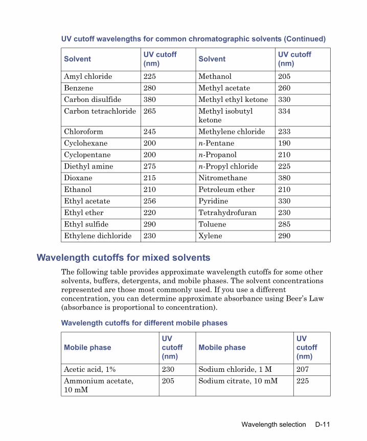
Wavelength cutoffs for mixed solventsThe following table provides approximate wavelength cutoffs for some other solvents, buffers, detergents, and mobile phases. The solvent concentrations represented are those most commonly used. If you use a different concentration, you can determine approximate absorbance using Beer’s Law (absorbance is proportional to concentration).
Amyl chloride 225 Methanol 205Benzene 280 Methyl acetate 260Carbon disulfide 380 Methyl ethyl ketone 330Carbon tetrachloride 265 Methyl isobutyl
ketone334
Chloroform 245 Methylene chloride 233Cyclohexane 200 n-Pentane 190Cyclopentane 200 n-Propanol 210Diethyl amine 275 n-Propyl chloride 225Dioxane 215 Nitromethane 380Ethanol 210 Petroleum ether 210Ethyl acetate 256 Pyridine 330Ethyl ether 220 Tetrahydrofuran 230Ethyl sulfide 290 Toluene 285Ethylene dichloride 230 Xylene 290
Wavelength cutoffs for different mobile phases
Mobile phaseUV cutoff (nm)
Mobile phaseUV cutoff (nm)
Acetic acid, 1% 230 Sodium chloride, 1 M 207Ammonium acetate, 10 mM
205 Sodium citrate, 10 mM 225
UV cutoff wavelengths for common chromatographic solvents (Continued)
Solvent UV cutoff (nm) Solvent UV cutoff
(nm)
Wavelength selection D-11

Ammonium bicarbonate, 10 mM
190 Sodium dodecyl sulfate 190
BRIJ 35, 0.1% 190 Sodium formate, 10 mM 200CHAPS, 0.1% 215 Triethyl amine, 1% 235Diammonium phosphate, 50 mM
205 Trifluoracetic acid, 0.1% 190
EDTA, disodium, 1 mM 190 TRIS HCl [tris-(hydroxym-ethyl)- aminoethane, hydrochloride], 20 mM, pH 7.0, pH 8.0
202, 212
HEPES (N-2-hydroxy-ethyl- piperazine-N1-2-ethane-sulfonic acid), 10 mM, pH 7.6
225 Triton-X™ 100, 0.1% 240
Hydrochloric acid, 0.1% 190 Waters PIC® Reagent A, 1 vial/liter
200
MES [2-(N-morpholine) ethane- sulfonic acid], 10 mM, pH 6.0
215 Waters PIC Reagent B-6, 1 vial/liter
225
Potassium phosphate, monobasic, 10 mM dibasic, 10 mM
190190
Waters PIC Reagent B-6, low UV, 1 vial/liter
190
Sodium acetate, 10 mM 205 Waters PIC Reagent D-4, 1 vial/liter
190
Wavelength cutoffs for different mobile phases (Continued)
Mobile phaseUV cutoff (nm)
Mobile phaseUV cutoff (nm)
D-12 Solvent Considerations
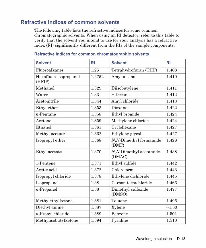
Refractive indices of common solventsThe following table lists the refractive indices for some common chromatographic solvents. When using an RI detector, refer to this table to verify that the solvent you intend to use for your analysis has a refractive index (RI) significantly different from the RIs of the sample components.
Refractive indices for common chromatographic solvents
Solvent RI Solvent RIFluoroalkanes 1.25 Tetrahydrofuran (THF) 1.408Hexafluoroisopropanol (HFIP)
1.2752 Amyl alcohol 1.410
Methanol 1.329 Diisobutylene 1.411Water 1.33 n-Decane 1.412Acetonitrile 1.344 Amyl chloride 1.413Ethyl ether 1.353 Dioxane 1.422n-Pentane 1.358 Ethyl bromide 1.424Acetone 1.359 Methylene chloride 1.424Ethanol 1.361 Cyclohexane 1.427Methyl acetate 1.362 Ethylene glycol 1.427Isopropyl ether 1.368 N,N-Dimethyl formamide
(DMF)1.428
Ethyl acetate 1.370 N,N-Dimethyl acetamide (DMAC)
1.438
1-Pentene 1.371 Ethyl sulfide 1.442Acetic acid 1.372 Chloroform 1.443Isopropyl chloride 1.378 Ethylene dichloride 1.445Isopropanol 1.38 Carbon tetrachloride 1.466n-Propanol 1.38 Dimethyl sulfoxide
(DMSO)1.477
Methylethylketone 1.381 Toluene 1.496Diethyl amine 1.387 Xylene ~1.50n-Propyl chloride 1.389 Benzene 1.501Methylisobutylketone 1.394 Pyridine 1.510
Wavelength selection D-13

Nitromethane 1.394 Chlorobenzene 1.5251-Nitropropane 1.400 o-Chlorophenol 1.547Isooctane 1.404 Aniline 1.586Cyclopentane 1.406 Carbon disulfide 1.626
Refractive indices for common chromatographic solvents (Continued)
Solvent RI Solvent RI
D-14 Solvent Considerations

Index
Numerics3-column selection valve 2-17
connections 2-176-column selection valve 2-18
Aabsorbance detector
parameters 5-33accessories 1-23air gaps 5-20alarms
bubble detect 5-9error log 5-12system pressure 5-9
alphanumeric keypad entries 3-9audience and purpose vAuto Add function 5-49, 5-52Auto Shutdown function 3-12, 3-17Auto Standards, specifying 5-47automatic runs 6-2automatic shutdown 3-17autosampler parameters 5-16, 5-21
Bbiohazard warning A-5bubble detection 5-9buffered solvents
components D-3flushing D-3, D-8preparing D-3, D-8
buffers, removing 3-44burst warning A-3bypass valve
controlling 8-11location 1-11
Ccarrier plate
description 1-13maintenance 7-48
caution symbol A-5chart out
parameters 2-25, 5-28signals 2-25terminals 2-25
check boxes, enabling and disabling 3-9
check plate height parameter 5-16, 5-21
chemical hazard warning A-5clock, setting 3-12color codes, wash tubing 2-15column
conditioning 4-19, 5-48connecting 2-16equilibrating 4-18equilibration 5-26information field 5-26position 5-26re-equilibration 5-24selection 5-26temperature 2-26
column heaterdescription 1-23diagnostic 8-14, 8-21disabling 5-25location 1-2setting temperature 5-25
column heater/coolerdescription 1-23diagnostic 8-21disabling 5-25
Index-1

setting temperature 5-25column regeneration valve 1-26, 2-19,
5-27column selection valve
connecting 2-16condensation waste outlet 2-13conditioning the column 4-19Configuration screen
keys 3-11configuring
plate types 3-19RS-232 valves 2-27, 3-24separations module 3-10
controlled by MassLynx mode 6-3custom plates 3-21cycle time
comparison 6-17high-throughput 6-9, 6-14, 6-17optimizing 1-16
Ddate format, selecting 3-11defrosting, sample heater/cooler 8-20degasser, in-line
considerations 1-8equilibrating 4-17installing vent tubing 2-11mode 5-10operating modes 3-32screen 5-10solvent use 1-8theory of operation 1-8
degassingbenefits D-9solvents 1-8, D-8
degassing efficiency 1-8detector 2-8
absorbance parameters 5-33drip tray 2-9
event actions 5-36events parameters 5-34parameters 5-31RI parameters 5-34setting parameters 5-36
Detector screen 5-33diagnostic tests and functions
column heater 8-14column heater ramp and decay 8-21defrosting sample cooler 8-14display 8-14, 8-19firmware checksum 8-14GPV test method 8-14head removal and replacement
8-13I/O signals 8-13, 8-17injection valve 8-10keypad 8-13, 8-19needle replacement 8-14other 8-12pulse seal wash 8-11pump head removal and
replacement 8-17sample heater/cooler 8-14sample heater/cooler defrosting
8-20sample heater/cooler ramp and
decay 8-19seal-wash prime 8-5service 8-6startup routines 3-2static leak 8-15turn off GPV 8-14
digital signal connections 2-27direct functions
conditioning the column 4-19dry prime 4-12equilibrating the system 4-18injecting samples 4-19
Index-2

menu 4-10wash plungers 4-23wet prime 4-16
display diagnostic 8-14, 8-19drain pump 1-10, 8-8drip tray, installing 2-9dry prime 4-12
Ee2795
components 1-2description 1-2front view 1-2powering-on 3-2site selection 2-2standard configuration 1-15
EC Authorized Representative vielectrical power requirements 2-6electrical symbols A-13Empower software
configuring for use with 1-20, 3-25Ethernet connection for 2-29IEEE connection for 2-29
equilibratingcolumn 5-26Sample Set function 5-49solvents 5-51system 4-18, 5-24
equipment guidelines iv, A-6error log
alarms 5-12error messages 8-38Ethernet
configuring 2-29connections 2-29supported configurations 1-20
Ethernet Switch Communications Kit 2-29
event switchesdescription 2-26
I
initial state 5-28events
detector events table 5-34gradient table 5-10I/O display 5-28
Events In, defining 3-12
Ffirmware and software requirements
2-4firmware checksum
diagnostic function 8-14flammable solvents A-4flow path
parameter 5-24sample management system 1-11
flow rateramp 5-10rapid equilibration parameters
5-24signal 2-25
front panelkeypad 3-5Main screen 3-2screen keys 3-4
full loop overfill parameter 5-18Functional view 5-41
Ggas solubility D-9GPV
controlling 8-10creating test method 8-14turning off 8-14
gradientcontrolling the GPV valve 8-10events table 5-10screen key 5-10
Index-3
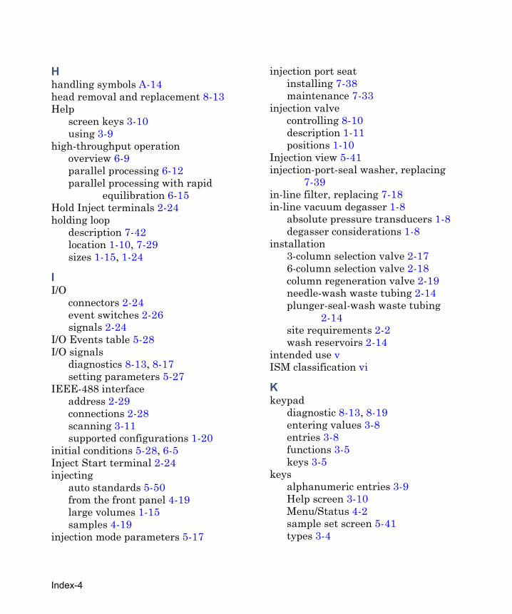
Hhandling symbols A-14head removal and replacement 8-13Help
screen keys 3-10using 3-9
high-throughput operationoverview 6-9parallel processing 6-12parallel processing with rapid
equilibration 6-15Hold Inject terminals 2-24holding loop
description 7-42location 1-10, 7-29sizes 1-15, 1-24
II/O
connectors 2-24event switches 2-26signals 2-24
I/O Events table 5-28I/O signals
diagnostics 8-13, 8-17setting parameters 5-27
IEEE-488 interfaceaddress 2-29connections 2-28scanning 3-11supported configurations 1-20
initial conditions 5-28, 6-5Inject Start terminal 2-24injecting
auto standards 5-50from the front panel 4-19large volumes 1-15samples 4-19
injection mode parameters 5-17
injection port seatinstalling 7-38maintenance 7-33
injection valvecontrolling 8-10description 1-11positions 1-10
Injection view 5-41injection-port-seal washer, replacing
7-39in-line filter, replacing 7-18in-line vacuum degasser 1-8
absolute pressure transducers 1-8degasser considerations 1-8
installation3-column selection valve 2-176-column selection valve 2-18column regeneration valve 2-19needle-wash waste tubing 2-14plunger-seal-wash waste tubing
2-14site requirements 2-2wash reservoirs 2-14
intended use vISM classification vi
Kkeypad
diagnostic 8-13, 8-19entering values 3-8entries 3-8functions 3-5keys 3-5
keysalphanumeric entries 3-9Help screen 3-10Menu/Status 4-2sample set screen 5-41types 3-4
Index-4

Llabels, solvent 5-11large-volume injections 1-16Loading view 5-41local control. See standalone modelocating wells 3-40, 4-21lockpin, controlling 8-11loop
holding loop size 1-15, 1-24maintenance 7-43sample loop size 1-15
loop parametersoff-line 5-19option 5-17overfill 5-18
MMain screen, description 3-2maintenance
injection port seat 7-33, 7-38injection-port-seal washer 7-39needle assembly 7-30plate carrier 7-48preventive 7-3protocol 7-3safety and handling 7-2sample compartment 7-46sample loop 7-43sample management system 7-20schedule 7-3solvent management system
overview 7-5syringe 7-22, 7-24
mass spectrometer shock hazard A-4MassLynx software
configuring for use with 1-22, 3-27control 2-5, 6-3documentation 2-5setup 1-22
I
Menu/Status key, using 4-2methods
deleting 5-6GPV test 8-14parameters 5-7renaming 5-6running 5-37storage 1-5viewing 5-6
Methods screen 5-36Millennium software
configuring for use with 1-21, 3-27, 3-28
setup 1-21miscibility of solvents D-5mobile phase
compatibility D-2composition 5-8degassing D-9flushing system with 3-44miscibility D-5parameters 5-8viscosity D-8
Mobile Phase screen 5-8monitoring system status 4-2Motors and Valves
diagnostic test 8-7motors, controlling 8-9
Nnames, selecting user 4-2needle assembly
changing 8-14description 1-12installing 7-30positioning for replacement 8-14
needle depth offset parameter 5-16needle washing
description 1-11
Index-5
priming 3-35sample set function 5-48solvent 3-35waste tubing 2-14
needle-wash pump 1-10No Interaction mode 1-18, 3-26
Oopen-access plates 1-12, 1-26Operate Gradient by Event In
configuring for use with 1-22, 3-29setup 1-22
options 1-23column selection valves 2-16description 1-23drip tray 2-9hardware 1-23holding loop sizes 1-15, 1-24, C-3installed list 3-12plates C-5sample loop sizes 1-15, 1-24, C-3screen key 1-23syringe sizes 1-15, 1-24, C-3
options and accessories 1-23organic solvents, using 4-17output line, identifying 2-16output signals 2-25overfill parameter 5-18
Pparallel processing
description 1-11increasing throughput 6-12with rapid equilibration 1-12, 6-15
parametersabsorbance detector 5-33alarm 5-12aspirate air 5-20autosampler 5-16autosampler wash 5-21
chart out 5-28check plate height 5-21column 5-25column information 5-26configuration 3-11detector 5-31, 5-36detector events 5-34, 5-35entering values 3-8flow path 5-24gradient events 5-10I/O events 5-28I/O signals 5-27injection mode 5-17mobile phase 5-8needle depth offset 5-16parallel processing 6-14plate type 3-20pre-column volume 5-18purge solvent 5-23rapid equilibration 5-21, 5-23, 6-16refractive index 5-34sample 5-14sample set table 5-45seek well bottom 5-20separation method 5-7Status screen 4-4wash solvent 5-22
plate carriercleaning 7-48description 1-13loading 3-38maintenance 7-46
plate parameters 3-20, 5-20, 5-41plates
carrier 1-13color-coded 3-39configuration screen 3-19covers 1-13custom 3-21
Index-6

dimensions C-5editing 4-21height 5-21loading 3-38microtiter 1-12navigation 3-6open-access 1-12, 1-26optional configurations C-5Plate Loading view 5-41plate logic 3-40preconfigured 3-19types 3-19well selection 4-21, 5-45
plunger seals, replacing 7-9plunger stroke volume, preferred 1-7plunger, cleaning/replacing 7-14, 7-16,
7-18plunger-seal-wash
parameters 5-11pump priming 3-33specifying time interval 5-11waste tubing installation 2-14
Pool Samples function 5-49pooling
sample gaps 5-55samples 5-49, 5-54
post-run delay 5-19power connections 2-6power requirements 2-6power supply 1-5powering-off 3-44powering-on 3-2pre-column volume
description 5-18determining 6-18
preconfigured plate types 3-19preferred stroke volume 5-11pressure units, selecting 3-11prime
I
needle-wash pump 3-35plunger-seal-wash pump 3-33sample set function 5-48solvent management system 3-34
primingdry prime 4-12wet prime 4-16
printingconfiguration list 3-22detector events 5-31I/O events table 5-31reports 3-12sample set 5-42sample set views 5-42using screen keys 5-12Well Selector screen 4-22
processingparallel 1-11, 6-9, 6-12parallel with rapid equilibration
1-12, 6-9, 6-15sequential 6-9, 6-10
pulsing the seal wash 8-11pump
description 1-9drain 1-9, 1-10needle-wash 1-9, 1-10plunger-seal-wash 8-4
pump head, removing 7-7pump plunger
cleaning 7-14replacing 7-15
purgecycle 1-11solvent parameters 5-23valve 8-11
purpose and audience v
Rramp and decay diagnostic 8-15
Index-7

rapid equilibrationdescription 1-12parameters 5-21, 5-23, 6-20processing 6-9, 6-15values 6-19
record-keeping functions 1-4re-equilibrating, column 5-24refractive index
common solvents D-13detectors 5-32parameters 5-34
refresh syringeafter installation 7-26function 3-36
regeneration valve, column 5-27reinitializing the system 4-2Remote Control mode 1-21
configuring 3-25Empower control 1-18MassLynx 3-27Millennium Chromatography
Manager 3-28Operate Gradient by Event In 3-29RS-232 3-30supported IEEE-488 and Ethernet
configurations 1-18removing
seal wash assembly 7-7repeatability, improvement of 1-16replacing
injection port seat 7-33injection-port-seal washer 7-39inlet check valves 7-16in-line filter 7-18plunger seal 7-9pump head face seal 7-10pump head seals 7-9pump plunger 7-14sample loop 7-43
seal wash assembly seals 7-12syringe 7-22
reports, defining 3-13reservoirs
installing 2-10installing caps 3-31, D-2installing wash 2-14positioning 3-31, D-2preparing solvent 3-31
resuming operation 6-9RI See refractive indexrows
linking 5-56unlinking 5-57
RS-232 controlconfiguring for use with 1-22, 3-30setup 1-22
RS-232 interface, parameters 2-27RS-232 valves, configuring 2-27, 3-24run
methods 5-37stat 6-7stopping 6-8
run samples control 6-3
Ssafety advisories A-1sample
diffusion 6-13gaps 5-55loading 3-38parameters 5-14plates 1-12pooling 5-49, 5-54, 5-55temperature 2-26
sample compartmentaccessing 7-46cleaning 7-46, 7-48
sample heater/cooler
Index-8

defrosting 8-14, 8-20description 1-23diagnostic 8-14ramp and decay test 8-19
sample looplocation 1-10maintenance 7-43replacing 7-43setting size 3-11sizes 1-15, 1-24
sample management systemcomponents 1-12, 7-21description 1-9features 1-11flow paths 1-11maintenance 7-20, 7-21needle-wash prime 3-35overview 1-9preparing 3-34refresh syringe function 3-36spare parts list C-3syringe 1-14three-axis sampling mechanism
1-13sample pooling
Pool Samples function 5-49, 5-54using gaps 5-55
sample set, definition 5-3sample sets
Auto Add function 5-49creating 5-36, 5-37deleting 5-40description 5-36editing 5-36, 5-38equilibrating solvents 5-51Equilibration function 5-49Functional view 5-41high-throughput 6-9Injection view 5-41
I
linking rows 5-56Loading view 5-41locking 5-39maximum number of rows 5-46modifying while running 6-7, 6-8needle-wash function 5-48parameter values 5-45Plate Loading view 5-41prime function 5-48renaming 5-39screen 5-37screen keys 5-41stat run 6-7table parameters 5-45unlinking rows 5-57unlocking 5-39viewing 5-40views 5-41
scheduled maintenance 7-3screen area 3-2screen display
modes 3-4overview 3-3
screen keysAuto Add dialog box 5-54auto standards dialog box 5-51Configuration screen 3-11detector events table 5-31function 3-4Functional view 5-41gradient table 5-31I/O events table 5-31Injection view 5-42Loading view 5-43making alphanumeric entries 5-3Plate Loading view 5-44sample set 5-41wash 5-21
seal replacement
Index-9

pump head face 7-10seal wash assembly 7-12
seal wash assembly, replacing seals 7-12
seal wash, description 1-7seek well bottom parameter 5-20sensors diagnostic 8-6separation method
definition 5-2detector parameters 5-31
separation method parametersalarm responses 5-12column 5-25I/O signals 5-27Mobile Phase screen 5-3rapid equilibration 5-21Sample screen 5-14wash 5-21
separation methodscopying 5-4, 5-38deleting 5-6editing 5-4locking 5-5parameters 5-7renaming 5-6running 5-37unlocking 5-5viewing 5-6
sequential processing 6-9sequential reference schemes 3-40serial number, location 1-14, 2-5service utilities 8-6set clock function 3-12shutdown
automatic 3-17powering-off 3-45
signal connectionsdigital 2-27Ethernet 2-29
I/O 2-23IEEE-488 2-28RS-232 2-27testing 8-17
site requirements 2-2solvent
buffered solvents 3-44installing reservoirs 2-10removing buffers 3-44tubing identification 2-10vacuum degassing 1-8
solvent management systemcomponents 7-5degasser 1-8flow rate ramp 5-10head removal 8-17preparing 3-30priming 3-34, 4-12, 4-16static leak diagnostic 8-15wash plungers 4-23
solventsacids D-4blending 1-8buffered D-3, D-8compatibility D-2labels 5-11, 5-22list 5-11, 5-22miscibility D-5miscibility numbers D-7needle-wash 3-35preparing reservoirs 3-31purge 5-23quality D-2refractive indices D-13use of organic 4-17UV cutoff D-10viscosity D-8
spare partssample management system C-3
Index-10

solvent management system C-2spill tray waste outlet 2-13standalone mode
No Interaction mode 1-18System Controller mode 1-17
standards, running 5-50startup
diagnostic tests 3-2kit 2-5routine 4-2
stat run 6-7Status screen
layout 4-9parameters 4-4
status, monitoring 4-2stop flow
programming terminals 3-13terminals 2-24
stopping a run 6-8storage capacity 1-5stroke volume 5-11symbols
caution A-5electrical A-13handling A-14warning A-2
syringedescription 1-9, 1-14draw rate 5-15installing 7-24modifying configuration
parameters 7-26options 1-24positions 8-9refresh 3-36refreshing 5-48, 7-26removing 7-22replacing 7-22setting size 3-11
I
sizes 1-14, 7-25syringe assembly, description 1-14System Controller mode 1-17, 3-26system pressure 2-25system status, monitoring 4-2
Ttemperature
column 2-26effects on solubility D-9sample 2-26, 5-15
three-axis sampling mechanism 1-13three-column selection valve
description 1-26time and date, setting 3-12troubleshooting
basic 8-24chromatography 8-26hardware 8-33sample management system 8-37solvent management system 8-35system 8-33
tubingcolor codes 2-15needle-wash 2-14
Uunpacking instructions 2-5unpacking the separations module 2-4user name
entering 3-9selecting 4-2
Vvacuum degasser, description 1-8valves
3-column selection 2-176-column selection 2-18bypass 1-11, 8-7column regeneration 2-19, 5-27
Index-11

column selection 2-16controlling positions 8-11description 1-9GPV 8-10, 8-14injection 1-11purge 8-7types 1-9wash 8-7waste 8-7
vent tubing, installing 2-11vials
cap diameter limits 1-13holders 1-12
volumedetermining pre-column 6-18large-volume injections 1-16pre-column 5-18preferred stroke 5-11
Wwarning symbols A-2, A-6wash
autosampler 5-21parameters 5-21plunger-seal 5-11reservoirs 2-14screen key 5-21solvents 5-22tubing color codes 2-15tubing location 2-15valve 8-11
wash plungers 4-23wash sequences, purge-wash-purge
3-32waste
tubing 2-14valve 8-11
waste line connectionscondensation waste 2-13
spill tray 2-13Waters Technical Service, contacting
8-25wavelength selection D-10well location
numerical 3-40plate logic 3-40selecting 4-21, 5-45sequential reference schemes 3-40using the well selector 4-21
wellsdeselecting all wells 4-22locating 3-40, 4-21selecting 4-21, 5-45selecting all wells 4-22single well 4-22
wet prime 4-16
XXYZ needle assembly, description 1-12
Index-12