Embed Size (px)
Citation preview

Waters 2700Sample Manager
Operator’s Guide
34 Maple StreetMilford, MA 01757
242101TP, Revision 0

NOTICE
The information in this document is subject to change without notice and should not be construed as a commitment by Waters Corporation. Waters Corporation assumes no responsibility for any errors that may appear in this document. This manual is believed to be complete and accurate at the time of publication. In no event shall Waters Corporation be liable for incidental or consequential damages in connection with, or arising from, the use of this manual.
© 1997 WATERS CORPORATION. PRINTED IN THE UNITED STATES OF AMERICA. ALL RIGHTS RESERVED. THIS BOOK OR PARTS THEREOF MAY NOT BE REPRODUCED IN ANY FORM WITHOUT THE WRITTEN PERMISSION OF THE PUBLISHER.
Millennium and Waters are registered trademarks of Waters Corporation.
Windows, Windows NT, and Windows 95 are trademarks and Microsoft is a registered trademark of Microsoft, Inc.
All other trademarks are the sole property of their respective owners.
The quality management system of Waters’ chromatography applications software design and manufacturing facility, Milford, Massachusetts, complies with the International Standard ISO 9001 Quality Management and Quality Assurance Standards. Waters’ quality management system is periodically audited by the registering body to ensure compliance.
2
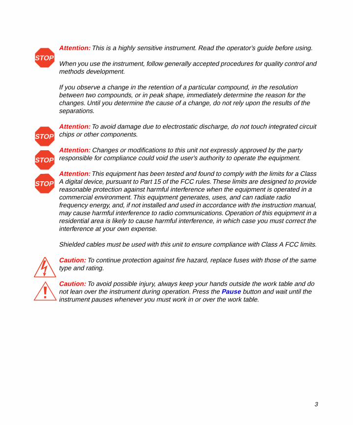
Attention: This is a highly sensitive instrument. Read the operator’s guide before using.
When you use the instrument, follow generally accepted procedures for quality control and methods development.
If you observe a change in the retention of a particular compound, in the resolution between two compounds, or in peak shape, immediately determine the reason for the changes. Until you determine the cause of a change, do not rely upon the results of the separations.
Attention: To avoid damage due to electrostatic discharge, do not touch integrated circuit chips or other components.
Attention: Changes or modifications to this unit not expressly approved by the party responsible for compliance could void the user’s authority to operate the equipment.
Attention: This equipment has been tested and found to comply with the limits for a Class A digital device, pursuant to Part 15 of the FCC rules. These limits are designed to provide reasonable protection against harmful interference when the equipment is operated in a commercial environment. This equipment generates, uses, and can radiate radio frequency energy, and, if not installed and used in accordance with the instruction manual, may cause harmful interference to radio communications. Operation of this equipment in a residential area is likely to cause harmful interference, in which case you must correct the interference at your own expense.
Shielded cables must be used with this unit to ensure compliance with Class A FCC limits.
Caution: To continue protection against fire hazard, replace fuses with those of the same type and rating.
Caution: To avoid possible injury, always keep your hands outside the work table and do not lean over the instrument during operation. Press the Pause button and wait until the instrument pauses whenever you must work in or over the work table.
STOP
STOP
STOP
STOP
3

Canadian Emissions Notice
This digital apparatus does not exceed the Class A limits for radio noise emissions from digital apparatus set forth in the Radio Interference Regulations of the Canadian Department of Communications.
Le présent appareil numérique n’émet pas de bruits radioélectriques dépassant les limites applicables aux appareils numériques de la classe A prescrites dans les règlements sur le brouillage radioélectrique édictés par le Ministère des Communications du Canada.
Symbols Used on the Waters 2700 Sample Manager
Direct current
Alternating current
Protective conductor terminal
Frame or chassis terminal
Caution, risk of electrical shock (high voltage)
Caution or refer to manual
4

2700 Sample Manager Information
Intended Use
The Waters 2700 Sample Manager can be used to analyze many compounds. When you develop methods, follow the “Protocol for the Adoption of Analytical Methods in the Clinical Chemistry Laboratory,” American Journal of Medical Technology, 44, 1, pages 30–37 (1978). This protocol covers good operating procedures and techniques necessary to validate system and method performance.
Biological Hazard
When you analyze physiological fluids, take all necessary precautions and treat all specimens as potentially infectious. Precautions are outlined in “CDC Guidelines on Specimen Handling,” CDC – NIH Manual, 1984.
Calibration
Follow acceptable methods of calibration with pure standards to calibrate methods. Use a minimum of five standards to generate a standard curve. The concentration range should cover the entire range of quality control samples, typical specimens, and atypical specimens.
Quality Control
Routinely run three quality-control samples. Quality-control samples should represent subnormal, normal, and above-normal levels of a compound. Ensure that quality-control sample results are within an acceptable range, and evaluate precision from day to day and run to run. Data collected when quality-control samples are out of range may not be valid. Do not report this data until you ensure that chromatographic system performance is acceptable.
5

Table of Contents
How to Use This Guide..................................................................... 15
Chapter 1 Introduction ...................................................................................... 19
1.1 Features................................................................................ 20
1.1.1 Hardware Features .................................................... 20
1.1.2 PC-Based User Interface........................................... 20
1.2 Operating Principles ............................................................. 22
1.2.1 Sample Flow .............................................................. 23
1.2.2 Software..................................................................... 24
1.2.3 Control and Communications .................................... 26
1.2.4 HPLC System ............................................................ 26
1.3 Hardware Components ......................................................... 27
1.3.1 Work Table ................................................................. 27
1.3.2 X/Y/Z Robotic Module with Probe Arm ...................... 27
1.3.3 Pumps........................................................................ 28
1.3.4 Injector ....................................................................... 29
1.3.5 Wash Station.............................................................. 29
1.4 Option and Accessories ........................................................ 30
1.4.1 Optional Diverter Valve for Fraction Collection........... 30
1.4.2 Accessories ............................................................... 30
6 Table of Contents

Chapter 2 Installation ....................................................................................... 31
2.1 Prerequisites ......................................................................... 32
2.1.1 Required Materials .................................................... 32
2.1.2 Required Software ..................................................... 32
2.1.3 Site Requirements ..................................................... 32
2.2 Unpacking ............................................................................. 33
2.2.1 Inspecting the Shipping Container............................. 34
2.2.2 Unpacking the Instrument.......................................... 34
2.2.3 Unlocking the Arm ..................................................... 34
2.3 Installing the Z-Rack, Probe Guide, and Probe..................... 35
2.3.1 Installing the Z-Rack .................................................. 36
2.3.2 Installing a Probe Guide ............................................ 36
2.3.3 Installing the Probe, Probe Tubing, and Insulation Block.......................................................................... 37
2.4 Making Fluidic Connections .................................................. 38
2.4.1 Installing the Syringe Pump Tubing ........................... 38
2.4.2 Installing the Wash Pump Tubing............................... 40
2.4.3 Installing the Injector Tubing ...................................... 41
2.5 Making Signal Connections .................................................. 42
2.5.1 Installing the Communications Cable ........................ 43
2.5.2 Installing the Signal Cable ......................................... 43
2.5.3 Installing the Power Cord........................................... 45
2.6 Installing the Software........................................................... 45
2.6.1 Setting Up the 2700 Project with Millennium ............. 46
Table of Contents 7

2.6.2 Understanding the 2700 Sample Manager Windows.................................................................... 47
2.7 Installing the Syringe............................................................. 49
2.8 Initializing and Priming .......................................................... 51
2.8.1 Initializing the Probe and Syringe Pump.................... 51
2.8.2 Priming the Pumps .................................................... 52
2.9 Changing the Sample Loop .................................................. 52
2.10 Installing the Shields ........................................................... 54
Chapter 3 Operation ......................................................................................... 56
3.1 Starting the Operation........................................................... 56
3.1.1 Opening the Project with Millennium ......................... 57
3.1.2 Opening the Program in Stand-Alone Mode.............. 57
3.2 Configuring the Hardware ..................................................... 57
3.3 Setting Up Workspaces......................................................... 60
3.3.1 Selecting a Workspace .............................................. 60
3.3.2 Creating a Customized Workspace ........................... 62
3.3.3 Checking the Probe Calibrations ............................... 63
3.4 Setting Up Sample Groups ................................................... 70
3.5 Running a Method................................................................. 73
3.5.1 Preparing for a Run ................................................... 75
3.5.2 Performing a Run....................................................... 76
3.5.3 Setting Up Fraction Collection ................................... 78
3.5.4 Setting Up to Pool Fractions ...................................... 80
3.5.5 Setting Up Reagent Addition ..................................... 83
8 Table of Contents
3.5.6 Setting Up Serial Dilution........................................... 85
3.5.7 Injecting the Samples ................................................ 87
3.5.8 Changing Parameters ................................................ 90
3.5.9 Changing Samples .................................................... 90
3.5.10 Cleaning the Instrument .......................................... 91
Chapter 4 Maintenance .................................................................................... 92
4.1 Maintenance Considerations ................................................ 93
4.2 Replacing the Probe ............................................................. 94
4.3 Replacing the Insulation Block and Cable............................. 95
4.4 Maintaining a Syringe ........................................................... 96
4.4.1 Replacing a Syringe .................................................. 96
4.4.2 Inspecting the Syringe Seal ....................................... 97
4.4.3 Replacing the Syringe Seal ....................................... 98
4.5 Cleaning the X/Y/Z Mechanism .......................................... 100
4.6 Replacing the Tubing........................................................... 102
4.7 Replacing the 4-Port Syringe Valve .................................... 103
4.8 Cleaning and Lubricating the Lead Screw .......................... 105
4.9 Replacing the Fuses ........................................................... 106
Chapter 5 Diagnostics and Troubleshooting ................................................... 108
5.1 Safety and Handling............................................................ 108
5.2 Error Messages................................................................... 110
5.3 Fluidics................................................................................ 112
5.4 Troubleshooting................................................................... 113
Table of Contents 9

Appendix A Specifications ................................................................................. 119
Appendix B Spare Parts and Options ................................................................ 123
B.1 Spare Parts......................................................................... 123
B.2 Startup Kit........................................................................... 126
B.3 Fraction Collection Option .................................................. 128
Appendix C Warranty Information ...................................................................... 129
C.1 Limited Express Warranty................................................... 129
Appendix D Solvent Considerations................................................................... 133
D.1 Introduction......................................................................... 133
D.2 Solvent Miscibility ............................................................... 134
D.3 Buffered Solvents ............................................................... 137
D.4 Head Height........................................................................ 138
D.5 Solvent Viscosity................................................................. 138
D.6 Mobile Phase Solvent Degassing ....................................... 138
D.6.1 Gas Solubility .......................................................... 138
D.6.2 Solvent Degassing Methods.................................... 139
D.6.3 Solvent Degassing Considerations.......................... 140
Index .......................................................................................... 141
10 Table of Contents
List of Figures
1-1 2700 Sample Manager .................................................................. 191-2 Typical Sample Flow ...................................................................... 241-3 Data Flow with the Millennium Chromatography Manager ............ 251-4 Typical System Setup .................................................................... 261-5 Major Hardware Components........................................................ 271-6 Syringe Pump and Wash Pump..................................................... 28
2-1 Primary Installation Steps.............................................................. 312-2 Unlocking the X/Y/Z Robotic Arm .................................................. 352-3 Installing the Z-Rack ...................................................................... 362-4 Installing the Probe........................................................................ 372-5 Installing the Syringe Pump and Wash Pump Tubing .................... 402-6 Connecting the Injector to an HPLC System ................................. 412-7 Injector Tubing Connections........................................................... 422-8 2700 Sample Manager in a Waters HPLC System........................ 432-9 Connecting the Cable to the Terminal Strip ................................... 442-10 Main Window ................................................................................. 482-11 Initialize Hardware Dialog Box ....................................................... 502-12 Installing a Syringe ........................................................................ 502-13 Installing the Sample Loop ............................................................ 532-14 Hardware Configuration Dialog Box............................................... 532-15 Installing the Shields...................................................................... 54
3-1 Operating the 2700 Sample Manager............................................ 563-2 Hardware Configuration Dialog Box............................................... 583-3 HPLC Column Parameter Setup Dialog Box ................................. 593-4 Selecting a Workspace .................................................................. 603-5 Workspace Editor Window............................................................. 61
11 Table of Contents
3-6 Select & Place Rack Sets Dialog Box............................................ 623-7 Reference Positions for Sample Racks and Containers ................ 643-8 Checking the Probe Calibrations in the Z-Direction....................... 653-9 Calibration Coordinates Dialog Box for Containers ....................... 663-10 Calibration Coordinates Dialog Box for Fixed Positions................. 683-11 Sample Group Editor Window........................................................ 713-12 Sampling Order.............................................................................. 713-13 Sample Group Editor Zoom Dialog Box......................................... 733-14 Performing a Run........................................................................... 743-15 Pooling Fractions Sequence .......................................................... 743-16 Reagent Addition Sequence.......................................................... 753-17 Serial Dilution Sequence ............................................................... 753-18 Run Window................................................................................... 773-19 Creating a Sample Group for Fraction Collection .......................... 783-20 Fraction Collection Setup Dialog Box ............................................ 793-21 Creating a Collection Group .......................................................... 803-22 Selecting Pretreatment Options..................................................... 813-23 Pooling Pretreatment Routine Dialog Box ..................................... 813-24 Contents of a Collection Group...................................................... 823-25 Sampling Order Buttons ................................................................ 823-26 Creating a Parent Group for Pooling Fractions .............................. 823-27 Reagadd Pretreatment Routine Dialog Box................................... 843-28 Serdilut Pretreatment Routine Dialog Box ..................................... 863-29 Current Run Status in Millennium QuickSet .................................. 89
4-1 Removing the Probe ...................................................................... 944-2 Disconnecting the Insulation Block Cable...................................... 954-3 Replacing the Syringe ................................................................... 974-4 Replacing the Syringe Seal ........................................................... 984-5 Removing the Seal on a 5-mL Syringe.......................................... 994-6 Installing the Seal on a 5-mL Syringe............................................ 994-7 Cleaning the Z-Rack .................................................................... 100
12 Table of Contents

4-8 Cleaning the Y- and Z-Axes ......................................................... 1014-9 Replacing the Tubing ................................................................... 1024-10 Removing the 4-Port Syringe Valve ............................................. 1034-11 Installing the Syringe Pump Tubing ............................................. 1044-12 Lubricating the Lead Screw ......................................................... 1054-13 Replacing a Fuse......................................................................... 106
Table of Contents 13

List of Tables
1-1 Preparing for Operation ................................................................ 23
2-1 Installation Site Requirements ...................................................... 332-2 I/O Signals .............................................................................. 442-3 Millennium-Required Custom Fields ........................................ 472-4 Entering Information in the 2700 Sample Manager Windows ... 48
3-1 HPLC Column Parameters ........................................................... 593-2 Default Workspaces ................................................................ 603-3 Using the Keyboard to Calibrate the Probe.............................. 643-4 Evaluating the Z-Direction Values............................................ 663-5 Recommended Z-Coordinates for Wash Station Positions ....... 693-6 Creating and Editing a Sample Group ..................................... 723-7 Entering Run Window Values .................................................. 773-8 Sequence of Events After Injection with Pretreatment Options 87
4-1 Suggested Maintenance Intervals ................................................ 92
5-1 Error Messages .......................................................................... 1105-2 Troubleshooting Hardware Problems ..................................... 113
A-1 Physical Specifications ............................................................... 119A-2 Environmental Specifications ................................................ 120A-3 Electrical Specifications ........................................................ 120A-4 System Operational Specifications ........................................ 121A-5 Liquid Handling Specifications............................................... 122A-6 Control, Computer, and Communication Specifications ......... 122
Table of Contents 14

B-1 Recommended Spare Parts ....................................................... 123B-2 Startup Kit............................................................................. 126B-3 Optional Diverter Valve for Fraction Collection....................... 128
C-1 2700 Warranty Periods ............................................................... 132
D-1 Solvent Miscibility ....................................................................... 135
Table of Contents 15

How to Use This GuidePurpose
The Waters 2700 Sample Manager Operator’s Guide describes the procedures for unpacking, installing, operating, maintaining, and troubleshooting the Waters 2700 Sample Manager. Also included is information about specifications, spare parts and options, warranty and service, and solvent considerations.
You can operate the Waters 2700 Sample Manager:
• By Dynamic Data Exchange (DDE) with the Millennium Chromatography Manager (version 2.15.n)
• As a stand-alone instrument controlled by the 2700 Sample Manager software
Audience
This guide is intended for use by individuals who need to install, operate, maintain, and/or troubleshoot the Waters 2700 Sample Manager. In order to install the 2700 Sample Manager, you should know how to set up and operate general laboratory instruments, including fluid handling, computer-controlled devices, and the Microsoft Windows platform.
Structure
The Waters 2700 Sample Manager Operator’s Guide has five chapters and four appendixes. Each page is marked with a tab and a footer to help you access information. The table below describes the material covered in each chapter and appendix.
Chapter/Appendix Description
Chapter 1, Introduction Describes the Waters 2700 Sample Manager features, operating principles, hardware components, and options and accessories.
Chapter 2, Installation Describes how to unpack and install the instrument, how to make fluidic and signal connections, and how to install the software.
Chapter 3, Operation Describes how to prepare the instrument for operation and how to operate the instrument.
How To Use This Guide 15

Related Documentation
Refer to the documentation supplied by the manufacturer of the peripheral instruments comprising your HPLC system. If you are using the Waters 2700 Sample Manager with the Millennium Chromatography Manager, refer to the table below for the relevant guides in the Millennium Chromatography Manager documentation set.
Chapter 4, Maintenance Describes how to perform routine maintenance procedures.
Chapter 5, Diagnostics and Troubleshooting
Describes diagnostic and troubleshooting procedures.
Appendix A, Specifications Describes the specifications of the instrument.
Appendix B, Spare Parts and Options
Provides a list of recommended and optional spare parts and accessories.
Appendix C, Warranty Information
Discusses warranty and service information.
Appendix D, Solvent Considerations
Provides information on solvent miscibility and degassing.
Title Description
Read Me First Provides a road map to using the Millennium documentation set, service and support specifics, and the Software License Agreement.
Millennium Chromatography Manager User’s Guide, Volumes I and II
Provides detailed information on the data acquisition and database software.
Getting Started Guide (LC/GC/IC)
Introduces the features and use of the Millennium chromatography software. Also includes step-by-step tutorials for using Millennium software (for LC/GC/IC processing).
Chapter/Appendix Description
16 How to Use This Guide

Millennium Online Help
The Millennium Chromatography Manager includes extensive online help as a convenient way to look up information while using the Millennium software. You access help from the windows and dialog boxes in the software. Help describes Millennium software windows, menus, menu selections, and dialog boxes. Help also includes procedures for performing tasks with the Millennium software.
Related Adobe™ Acrobat Reader Documentation
For detailed information about using the Adobe Acrobat Reader, refer to the Adobe Acrobat Reader Online Guide. This Online Guide covers procedures such as viewing, navigating and printing electronic documentation from Adobe Acrobat Reader.
Printing From This Electronic Document
Adobe Acrobat Reader lets you easily print pages, pages ranges, or the entire electronic document by selecting Print from the File menu. For optimum print quantity, Waters recommends that you specify a Postscript printer driver for your printer. Ideally, use a printer that supports 600 dpi print resolution.
Conventions Used in This Guide
This guide uses the following conventions to make text easier to understand.
• Purple Text indicates user action. For example:
Press 0, then press Enter for the remaining fields.
Millennium System Configuration Guide
Describes how chromatographic instrumentation is connected and addressed as part of the Millennium Chromatography Manager system. Also covers software installation, computer hardware installation, and operating requirements.
Quick Reference Guide Summarizes procedures for using the Millennium software. Also includes a summary of icons, tools, and buttons.
Millennium System Administrator’s Guide
Details the duties of the Millennium Chromatography Manager system administrator.
Title Description
How To Use This Guide 17

• Italic text denotes new or important words, and is also used for emphasis. For example:
An instrument method tells the software how to acquire data.
• Underlined, Blue Color text indicates hypertext cross-references to a specific chapter, section, subsection, or sidehead. Clicking this topic using the hand symbol automatically brings you to this topic within the electronic document. Right-clicking and selecting Go Back from the popup context menu brings you back to the originating topic. For example:
To install the instrument, you need the Startup Kit (see Appendix B, Spare Parts and Options).
Notes, Attentions, and Cautions
• Notes call out information that is important to the operator. For example:
Note: Zones must be in nonoverlapping chronological order.
• Attentions provide information about preventing possible damage to the system or equipment. For example:
Attention: To avoid probe damage, keep the tip of the probe at least 0.2 in. (0.5 cm) above the top surface of the rack.
• Cautions provide information essential to the safety of the operator. For example:
Caution: To avoid chemical or electrical hazards, always observe safe laboratory practices when you operate your system.
Caution: To avoid electrical shock and possible injury, remove the power cord from the left side of the instrument before you perform the procedures in this section.
STOP
18 How to Use This Guide
1
1Introduction
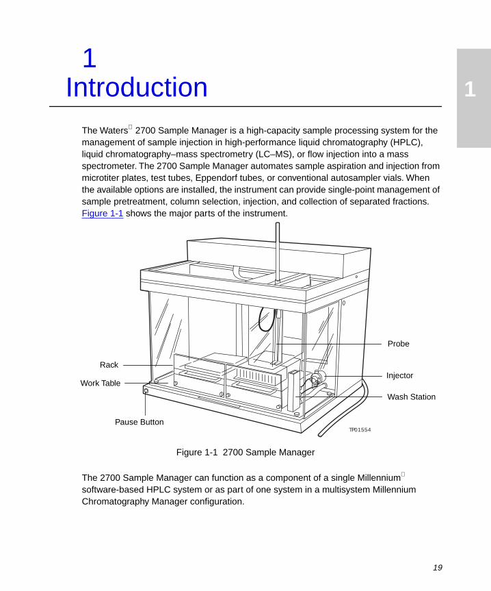
The Waters 2700 Sample Manager is a high-capacity sample processing system for the management of sample injection in high-performance liquid chromatography (HPLC), liquid chromatography–mass spectrometry (LC–MS), or flow injection into a mass spectrometer. The 2700 Sample Manager automates sample aspiration and injection from microtiter plates, test tubes, Eppendorf tubes, or conventional autosampler vials. When the available options are installed, the instrument can provide single-point management of sample pretreatment, column selection, injection, and collection of separated fractions. Figure 1-1 shows the major parts of the instrument.
Figure 1-1 2700 Sample Manager
The 2700 Sample Manager can function as a component of a single Millennium software-based HPLC system or as part of one system in a multisystem Millennium Chromatography Manager configuration.
TP01554
Wash Station
RackInjector
Work Table
Probe
Pause Button
19

1
The 2700 Sample Manager is controlled by software installed on a computer that is running Windows 3.1, Windows 95 , or Windows NT . The control software may be operated independently or with a DDE link to Waters Millennium Chromatography Manager (version 2.15.n) that is running Windows 3.1. The 2700 Sample Manager connects to the computer through an RS-232 port and triggers operation of an HPLC module by transistor-to-transistor logic (TTL).
1.1 Features
1.1.1 Hardware Features
Sample Trays
The sample trays are racks that hold a variety of samples:
• 2- or 6-microtiter plate racks in 96- and 384-well formats with either standard or deep wells
• 100-test tube rack for 13 x 100 mm tubes
• 100-tube racks for Eppendorf tubes
• 100-vial racks for autosampler HPLC vials
Pause Button
The Pause button stops vertical movement of the probe immediately, and stops all movement after completing the current request.
Work Table
The work table accommodates the racks that hold the sample containers. A drip tray catches spills.
1.1.2 PC-Based User Interface
Workspace Editor
The Workspace Editor window allows you to configure the work table to accept the trays and racks in various combinations.
Sample Group Editor
The Sample Group Editor window allows you to select the array of positions within the racks that can be accessed during the run of a sampling routine.
20 Introduction

1
Hardware Configuration
The Hardware Configuration dialog box allows you to enter a change to system parameters such as sample loop volume, syringe size, and volume of fluid in the system. You also enter parameters for the optional fraction collection and column selection functions.
Initialize Hardware
The Initialize Hardware dialog box allows you to:
• Run a logic checking routine for the robotic probe arm and the syringe pump
• Prime or purge the syringe pump
• Start and stop the wash pump
• Position the syringe motor to allow a change of the syringe
Run
The Run window allows you to enter the parameters for a sampling routine, including:
• Sample Group – You can select a previously defined group or a new group of sample positions from a pull-down menu.
• Number of injections – You can define the number of replicates up to 99 injections from a given position.
• Sample volume (µL) – You can enter a value up to the loop volume. The default value is based on the installed sample loop.
• Rinse volume (µL) – You can define the volume of solution used to wash the probe. Either the syringe pump or wash pump is automatically invoked, depending on the volume.
• Millennium Software Method Set – You can select among the currently available method sets from a pop-up menu.
• Run Time (minutes) – You can enter the time required for the completion of the HPLC separation.
• HPLC Column – You can change the name of a column to be used for the analyses, or you can select a column from a pop-up menu if you have an optional column switching valve for column selection.
• Pretreatment – You can select pooling, reagent addition, or serial dilution.
• Fraction Collection (FC) – If you have the diverter valve option, you can enter the parameters that will determine which fractions will be collected, where fractions will be collected, and how many fractions to collect for each peak or zone.
Features 21

1
In addition, you can enter the following system information:
• Workspace configuration in the Workspace Editor window
• Project name in the Millennium Method Set
• Name of analytical system in the Millennium Method Set
• Volume of the currently installed sample loop in the Hardware Configuration dialog box
During a run, the system displays:
• Position on the work table that is being accessed
• Sample number for the current tube within the selected sample group
• Injection number
• Operational status
Communications
Communications between the 2700 Sample Manager and other instruments in the HPLC system use the following:
• RS-232 port for control of the 2700 Sample Manager by software running on a Windows-based computer
• Terminal setup (TTL) to send signals to an HPLC module, data station, or switching valve
1.2 Operating Principles
The Waters 2700 Sample Manager is designed to move the probe to a specific location, aspirate sample using the syringe pump, move the probe to the injector or another location, dispense sample, move the probe to the wash station, and wash the probe.
The instrument has a single cap-piercing probe that moves in three dimensions and a syringe pump that aspirates and dispenses fluids. The injector transfers samples to your column. A wash pump performs high-volume washing and rinsing of the probe. If your instrument has the fraction collection option, the dispensing probe dispenses the collected fractions from the detector outlet.
The 2700 Sample Manager is controlled by software installed on a PC running Windows 3.1, Windows 95, or Windows NT. This software manages sequencing, sampling, and injection of the selected samples and provides a start signal to an HPLC module. When the 2700 Sample Manager software is installed on a Millennium workstation, it starts a run by creating a sample set in Millennium QuickSet and initiates the run.
22 Introduction

1
You create and save workspaces, sample groups, and run methods in the 2700 Sample Manager as shown in Table 1-1. You control the run in the Run window with the Start, Stop, and Pause buttons. You can also monitor the operational status of the current sample with the position, sample number, and injection number in the Run window.
1.2.1 Sample Flow
During operation, the sample flows through the 2700 Sample Manager, then to other instruments in the HPLC system. The following steps explain the process of sample flow:
1. The probe aspirates a sample from a sample container in a rack by moving the Z-rack to a sample well and down into the sample. With the syringe valve open, the syringe plunger draws down to pull sample into the probe tip.
2. The probe moves to the injector, the injector checks the valve position, then the probe dispenses the sample through the injector port into the sample loop.
3. The injector moves the valve to the Inject position, then the sample travels into the fluid stream, to the HPLC column, and to the detector. While the probe is still in the injector port, the syringe pump rinses the port with solvent.
4. If the diverter valve option is installed and fraction collection is selected, the diverter valve dispenses the fractions into wells or tubes in a rack.
Figure 1-2 summarizes the path of the sample as it flows through the 2700 Sample Manager.
Table 1-1 Preparing for Operation
Area Description
Workspaces Specify the commonly used racks and sample container arrangements.
Sample Groups Specify the pattern of sampling of the probe (such as left to right and back to front), including random individual samples and groups, as it aspirates samples.
Run Methods For each sample group, specify the number of injections, sample volume, rinse volume, Millennium Method Set (if applicable), run time, and HPLC column.
Operating Principles 23

1
Figure 1-2 Typical Sample Flow
1.2.2 Software
The 2700 Sample Manager includes a software program using drop-down menus that allow the operator to configure and execute methods. Refer to Section 2.6.2, Understanding the 2700 Sample Manager Windows, for more information on using the software to operate the instrument.
You can specify arrangements of racks on the work table of the 2700 Sample Manager using the Workspace Editor. Rectangular racks that hold microtiter plates, test tubes, HPLC vials, and Eppendorf tubes are simple to place using graphical design tools.
You use the 2700 Sample Manager as an autoinjector in any HPLC system or in an HPLC system controlled by the Waters Millennium Chromatography Manager software version 2.15.n, which is on a workstation operating with Windows. You use method sets developed in the Millennium Chromatography Manager to control the 2700 Sample Manager and other the HPLC system components. You set up a 2700 project in Millennium software, based on the 2700 project template that is provided. Refer to the Millennium documentation for information on creating method sets and other setup tasks. Figure 1-3 shows the relationship of the 2700 Sample Manager to the Millennium Chromatography Manager software.
Probe Aspirates Sample
Probe Transfers Sample into Sample
Loop
Sample Travels to Detector
Sample Is Injected into HPLC Column
Start Run
If Fraction Collection, Sample
Travels to 2700
Run Complete
24 Introduction

1
The following steps explain the processes shown in Figure 1-3:
1. The operator enters parameters for the run in the Workspace Editor window, the Sample Group Editor window, and the Run window.
2. When a run starts, the parameters applicable to the project being tested are transferred to a Millennium software sample set, where they become a permanent part of the Millennium database.
3. Samples are aspirated from the work table and are injected into the HPLC system, which is controlled by the Millennium software.
4. The Millennium software acquires data from the HPLC system using an assigned project and method set. The 2700 Sample Manager generates log files of the run.
5. The Millennium software processes the acquired HPLC data using the processing method specified in the method set. Data can be acquired and stored for reprocessing at a later time using the same method set or a different processing method or method set.
Figure 1-3 Data Flow with the Millennium Chromatography Manager
Millennium
Project
QuickSet
Windows Operating System
Version 2.15. n
Control
Control
Folder
Data
DDE Tool Kit
Data Real Timeor ReprocessStorage
Results
Waters 2700 Sample Manager
SoftwareLog File
HPLC Systemwith Column and
Detector
Other Reports
Operating Principles 25
1
1.2.3 Control and Communications
The 2700 Sample Manager is controlled by an RS-232 connection to a computer and the Waters Millennium Chromatography Manager. The interface software for the 2700 Sample Manager is a DDE/Tool Kit application that runs under Millennium software version 2.15.n.
The 2700 Sample Manager provides electrical control by 10 outputs (TTL). The 2700 Sample Manager can select a compatible HPLC column by sending a signal to a column switching valve.
Use the procedures in Section 2.5, Making Signal Connections, to set up the 2700 Sample Manager for control by a Millennium workstation.
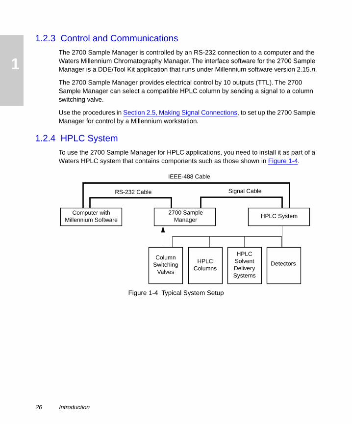
1.2.4 HPLC System
To use the 2700 Sample Manager for HPLC applications, you need to install it as part of a Waters HPLC system that contains components such as those shown in Figure 1-4.
Figure 1-4 Typical System Setup
RS-232 Cable Signal Cable
IEEE-488 Cable
Computer with Millennium Software
HPLC System2700 Sample
Manager
HPLC Columns
HPLC Solvent Delivery Systems
DetectorsColumn
Switching Valves
26 Introduction
1
1.3 Hardware Components
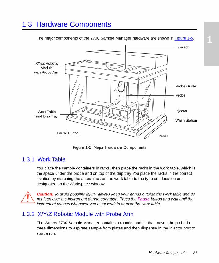
The major components of the 2700 Sample Manager hardware are shown in Figure 1-5.
Figure 1-5 Major Hardware Components
1.3.1 Work Table
You place the sample containers in racks, then place the racks in the work table, which is the space under the probe and on top of the drip tray. You place the racks in the correct location by matching the actual rack on the work table to the type and location as designated on the Workspace window.
Caution: To avoid possible injury, always keep your hands outside the work table and do not lean over the instrument during operation. Press the Pause button and wait until the instrument pauses whenever you must work in or over the work table.
1.3.2 X/Y/Z Robotic Module with Probe Arm
The Waters 2700 Sample Manager contains a robotic module that moves the probe in three dimensions to aspirate sample from plates and then dispense in the injector port to start a run:
TP01554
Z-Rack
Wash Station
InjectorWork Tableand Drip Tray
Probe Guide
Probe
X/Y/Z Robotic Module
with Probe Arm
Pause Button
Hardware Components 27

1
• The x-axis moves the probe to the left and right.
• The y-axis moves the probe forward and backward.
• The z-axis moves the probe up and down.
The robotic module starts an HPLC run by moving the probe to aspirate sample from a stationary rack or plate, moving the probe to dispense sample into the injector port, loading sample into the sample loop, then actuating the injector valve to introduce sample into the flow stream.
1.3.3 Pumps
Syringe Pump
The syringe pump aspirates and dispenses fluids from sample containers, and dispenses fluids into the injector (Figure 1-6). It also washes the probe with volumes of solvent less than 800 µL.
Figure 1-6 Syringe Pump and Wash Pump
The syringe pump has a 4-port syringe valve at the head of the syringe. The valve rotates position to aspirate wash solvent through the inlet port on the left and dispense it through the outlet port on the right. The plunger of the syringe is attached to the plunger shaft, which is connected to a lead screw that moves the plunger up and down. To wash the probe, the syringe pump:
TP01560
OUTLET INLET
Syringe PumpWash Pump
4-Port Syringe Valve
28 Introduction

1
1. Draws solvent from a solvent container into the instrument through the left port of the 4-port syringe valve.
2. Pushes solvent out the right port of the syringe valve through the manifold block.
3. Dispenses solvent through the probe, which is then rinsed in the wash station.
Wash Pump
To wash the probe, the wash pump is triggered to start pumping solvent (wash fluid) whenever the rinse volume is at least 800 µL. The wash pump draws solvent from a solvent container, through the wash pump, and into the top port of the syringe valve. Solvent then travels out the right port of the syringe valve, through the manifold, through the probe to the wash station. Waste fluid drains from the wash station by gravity to the waste fluid container.
1.3.4 Injector
The 2700 Sample Manager has one fixed-loop sample injector with an injector port and a waste port. The standard sample loop is 20 µL. You can install sample loops with capacities from 5 µL to 5000 µL. The probe dispenses a sample through the port into the sample loop, where the injector injects the sample onto the column. The injector port is washed after each injection to prevent sample carryover.
1.3.5 Wash Station
The wash station contains a waste port and two wash ports. After completing a liquid handling function, the excess solvent is discarded in the waste port. The probe then moves to the wash port of the wash station to clean the probe. The program selects either the shallow or deep wash port:
• The probe is washed in the deep wash port when the rinse volume is greater than 800 µL.
• The probe is washed in the shallow wash port when the rinse volume is less than or equal to 800 µL.
Washing is accomplished by pumping solvent through the probe. The solvent flows around the outside of the probe and overflows into the waste port. The waste solvent travels by gravity through the waste tubing to a waste fluid container located below the instrument.
Hardware Components 29
1
1.4 Option and Accessories
The 2700 Sample Manager has one option and several accessories. Refer to Appendix B, Spare Parts and Options, for additional information on the optional diverter valve and the accessories.
1.4.1 Optional Diverter Valve for Fraction Collection
You can install a low pressure diverter valve kit (Waters Part No. 272006) to provide the 2700 Sample Manager with the ability to collect fractions from injected samples. The kit includes a diverter valve, mounting bracket, tubing, and fitting for installation. Follow the instructions that come with the option to install and configure it.
1.4.2 Accessories
You can customize the 2700 Sample Manager with the following accessories to suit your applications and site requirements:
• Sample loops of various sizes from 5 µL to 5000 µL. The instrument is provided with a 20-µL sample loop.
• Syringes of various sizes from 500 µL to 5000 µL. The instrument is provided with a 500-µL syringe.
• Test tube racks, HPLC vial racks, Eppendorf tube racks, and microtiter plate racks. The instrument is not provided with racks, sample containers, or solvent containers.
30 Introduction

2
2Installation
This chapter describes how to install the hardware, make fluidic and signal connections to the Waters 2700 Sample Manager, and install the software. Figure 2-1 shows the primary steps for installing the Waters 2700 Sample Manager.
Figure 2-1 Primary Installation Steps
Note: To install the 2700 Sample Manager, you should know how to set up and operate general laboratory instruments and computer-controlled devices, and how to handle solvents.
StartInstallation
StartInstallation
EndInstallation
Select Appropriate Site
Unpack and Inspect
Install Z-Rack, Probe Guide, and
Probe(s)
Make Fluidic Connections
Install the Software
Make Signal Connections
Install the Syringe
Install the Shields
Initialize and Prime
Change the Sample Loop
31 Installation

2
2.1 Prerequisites
2.1.1 Required Materials
To install the instrument, you need the Startup Kit (see Appendix B, Spare Parts and Options), which includes tools such as a flat-blade screwdriver and a metric Allen wrench set.
You also need:
• Waste fluid container (approximately twice the capacity of the solvent containers)
• Solvent (supply) containers
• Sample containers such as 2-mL HPLC vials, 1.5-mL Eppendorf tubes, 12 x 100 test tubes, and microtiter plates
• Injector tubing (0.009-inch internal diameter)
2.1.2 Required Software
To install the 2700 Sample Manager software program with the Millennium Chromatography Manager, you need:
• 2700 Sample Manager program diskettes
• Millennium Chromatography Manager, version 2.15.n, and Windows 3.1 on an IBM -compatible personal computer with a DB9 serial port or adapter
To install the 2700 Sample Manager software program as a stand-alone instrument, you need:
• 2700 Sample Manager program diskettes
• Windows 3.1, Windows 95 , or Windows NT on an IBM-compatible personal computer with a DB9 serial port or adapter
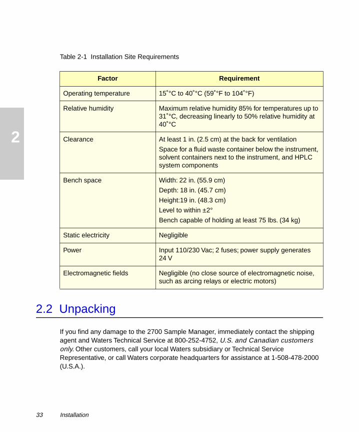
2.1.3 Site Requirements
Install the 2700 Sample Manager at a site that meets the requirements outlined in Table 2-1.
Prerequisites 32
2
2.2 Unpacking
If you find any damage to the 2700 Sample Manager, immediately contact the shipping agent and Waters Technical Service at 800-252-4752, U.S. and Canadian customers only. Other customers, call your local Waters subsidiary or Technical Service Representative, or call Waters corporate headquarters for assistance at 1-508-478-2000 (U.S.A.).
Table 2-1 Installation Site Requirements
Factor Requirement
Operating temperature 15 °C to 40 °C (59 °F to 104 °F)
Relative humidity Maximum relative humidity 85% for temperatures up to 31 °C, decreasing linearly to 50% relative humidity at 40 °C
Clearance At least 1 in. (2.5 cm) at the back for ventilation
Space for a fluid waste container below the instrument, solvent containers next to the instrument, and HPLC system components
Bench space Width: 22 in. (55.9 cm)
Depth: 18 in. (45.7 cm)
Height:19 in. (48.3 cm)
Level to within ±2°
Bench capable of holding at least 75 lbs. (34 kg)
Static electricity Negligible
Power Input 110/230 Vac; 2 fuses; power supply generates 24 V
Electromagnetic fields Negligible (no close source of electromagnetic noise, such as arcing relays or electric motors)
33 Installation

2
2.2.1 Inspecting the Shipping Container
Inspect the exterior of the container for possible shipping damage such as:
• Water damage or discoloration
• Cuts or gashes
• Collapsed corners
• Crushed top, sides, or bottom
• Other physical damage
Save the shipping container in case you need to move or ship the instrument in the future.
2.2.2 Unpacking the Instrument
Ensure that there is sufficient space to unpack the instrument and accessories.
Attention: To avoid overheating the 2700 Sample Manager, make sure there is at least 1 in. (2.5 cm) of clearance at the back of the instrument.
To unpack the instrument:
1. Remove the plastic wrap, if any, and the bands securing the carton to the pallet. Remove the top and the sides of the shipping carton, and the packing material.
Attention: To prevent damage, lift the instrument by the bottom. Do not lift the instrument by the robotic arm.
2. Remove the instrument from the bottom styrofoam cushion, the box bottom, and the bag, and place the instrument on the work surface.
3. Locate the power cord and signal cables.
4. Remove the Startup Kit.
5. Inspect the instrument for physical damage.
6. Open the Startup Kit and ensure that it includes all parts on the packing list (see Appendix B, Spare Parts and Options).
7. Open and inspect the options, accessories, and spare parts (see Appendix B, Spare Parts and Options) for damaged or missing parts.
2.2.3 Unlocking the Arm
The Startup Kit contains the metric Allen wrench set. To unlock the X/Y/Z robotic arm:
1. Use an Allen wrench (2.5 mm) to remove the two screws from the back of the top cover, then remove the top cover.
STOP
STOP
Unpacking 34

2
2. Use an Allen wrench (2.5 mm) to remove the transport screw, which is located in a through-hole on the upper-right side (Figure 2-2).
Figure 2-2 Unlocking the X/Y/Z Robotic Arm
3. Slowly slide the X/Y/Z robotic arm toward the center of the x-axis.
4. Lift out the transportation block from the right end cap, and save the transportation screw and block.
Attention: To prevent damage to the X/Y/Z robotic arm when moving, relocating, or shipping the 2700 Sample Manager, reinstall the transportation block before moving the instrument. Save the transportation screw and block.
5. Remove the packing material from the top of the frame. Remove the tie and tubing from the top of the probe guide. Remove the tie from the probe below the frame.
6. Replace the top cover with both screws.
2.3 Installing the Z-Rack, Probe Guide, and Probe
The X/Y/Z robotic arm, which holds the Z-rack, moves along the x- and y-axes. The Startup Kit contains the components you need for the installation procedure:
• Z-rack (Waters Part No. 272050)
• Probe guide (Waters Part No. 272052)
• Cap-piercing probe (Waters Part No. 272070) and probe tubing (Waters Part No. 272083)
TP01556
Transportation Block
Transport Screw
Hole for Solvent Container Tubing
STOP
35 Installation

2
2.3.1 Installing the Z-Rack
The Z-rack holds the probe guide, insulation block, and probe, and moves up and down.
Attention: To prevent damage to the Z-bearing, do not force the Z-rack into the Z-bearing. If the Z-rack does not slide easily into the Z-bearing, turn the square shaft on the underside of the arm.
To install the Z-rack:
1. Gently insert the Z-rack into the top of the Z-bearing with the teeth facing toward the left. Ensure that the flat area on the end of the Z-rack is toward the bottom (Figure 2-3).
Figure 2-3 Installing the Z-Rack
2. Position the Z-rack so that equal amounts are visible above and below the Y-frame.
2.3.2 Installing a Probe Guide
You install a probe guide on the Z-rack under the Y-frame. The probe guide provided in the Startup Kit holds one sample probe.
STOP
TP01561
Z-Rack
Z-Bearing
Y-Frame
Installing the Z-Rack, Probe Guide, and Probe 36

2
To install a probe guide:
1. Place the ring-shaped sleeve in the top of the probe guide.
2. Place the top of the probe guide up onto the bottom of the Z-rack and push upward as far as possible.
3. Use an Allen wrench (2.0 mm) to tighten the captive screw on the top right of the probe guide.
2.3.3 Installing the Probe, Probe Tubing, and Insulation Block
You install the cap-piercing probe and the insulation block on the Z-rack. The cap-piercing probe has a polytetrafluoroethylene (PTFE) coating and can pierce standard silicone-coated PTFE septa on HPLC vials.
To install the probe, probe tubing, and insulation block:
1. Remove the probe from the container.
2. Remove the insulation block from underneath the X/Y/Z robotic arm without disconnecting the cable. The insulation block for the single-probe guide has a pin at the back of the block that fits into the slot on the probe guide.
3. Insert the large end of the probe through the bottom of the sleeve in the insulation block and push upward (Figure 2-4).
Figure 2-4 Installing the Probe
TP01565
Probe Tubing
Z-Rack
Insulation Block Set Screw
Top of Probe
Insulation Block
Probe Set Screw
37 Installation

2
4. Insert the probe set screw into the threaded hole in the sleeve at the bottom of the insulation block. Use a small flat-blade screwdriver to gently tighten the probe set screw at the bottom of the insulation block.
5. Insert the probe tubing and push it down through the Z-rack until 1 in. (2.5 cm) is visible. Attach the probe tubing to the large end of the probe in the insulation block.
6. Install the insulation block onto the Z-rack until firmly seated. Ensure that the pin in the back of the insulation block is in the slot of the probe guide.
7. Use an Allen wrench (2.0 mm) to tighten the insulation block set screw on the upper-left side until it contacts the flat portion of the Z-rack. Do not overtighten the set screw.
2.4 Making Fluidic Connections
Solvents that are compatible with the 2700 Sample Manager can range from water and aqueous solutions to organic solvents. Refer to Appendix D, Solvent Considerations, for limitations. Ensure that the sample and sample matrix are soluble in the solvents that you use for elution, dilution, and washing.
Note: Mixing aqueous buffers and miscible organic solvents with each other can cause precipitation due to salt formation or solubility limitations. Precipitates can block the probe and interfere with aspiration of the sample.
The fluidic connections for the 2700 Sample Manager are as follows:
• Install the syringe pump tubing
• Install the wash pump tubing
• Install the injector tubing
Caution: Observe safe laboratory practices when you handle solvents. Refer to the Material Safety Data Sheets for the solvents you use.
Attention: To ensure proper drip protection, ensure that the tubing fittings are tightened before you operate the system.
2.4.1 Installing the Syringe Pump Tubing
The syringe aspirates and dispenses samples from wells, tubes, and vials and provides washes that are less than 800 µL to flush and prime the probe. The Startup Kit contains:
• Interconnect tubing (Waters Part No. 272081)
STOP
Making Fluidic Connections 38

2
• Reagent tubing (Waters Part No. 272082)
• Manifold block (Waters Part No. 272056)
You also need a 5/16-in. open-end wrench, which is not provided.
To install the tubing for the fluid path to the 4-port syringe valve of the syringe pump (Figure 2-5):
1. Use an Allen wrench (2.5 mm) and two washers and screws to install the manifold block on the right side panel over the transport screw hole.
2. Insert the fitting on the free end of the probe tubing from the Z-rack into the top of the manifold block, then tighten the fitting into the manifold block.
3. Install the interconnect tubing:
a. Insert one end of the tubing through the hole on the right panel near the manifold block (shown in Figure 2-2), then connect the tubing to the right port of the syringe pump.
b. Connect the other tubing fitting to the bottom of the manifold block.
Attention: To prevent spill damage to the 2700 Sample Manager, do not place solvent containers on top of the instrument. Place the solvent container at benchtop level to prevent any unintentional siphoning of solvent.
4. Install the reagent tubing:
a. Insert one end of the tubing through the hole on the right panel, then connect the tubing to the left port of the syringe pump.
b. Place the other tubing fitting into the solvent container.
5. Finger-tighten all fittings, then give them another 1/4-turn with a 5/16-in. wrench.
6. Ensure that all tubing does not interfere with the movement of the probe shield, probe guide, and probe.
7. Secure tubing through the clip under the top of the panel.
8. Place the solvent container at benchtop level to prevent any unintentional siphoning of solvent.
STOP
39 Installation

2
.
Figure 2-5 Installing the Syringe Pump and Wash Pump Tubing
2.4.2 Installing the Wash Pump Tubing
The wash pump provides washes that are greater than 800 µL to flush and prime the probe. The Startup Kit contains:
• Reagent tubing (Waters Part No. 272085)
• Wash interconnect tubing (Waters Part No. 272086)
Ensure that the solvent container is placed at benchtop level to prevent any unintentional siphoning of solvent.
To install the wash pump tubing (Figure 2-5):
1. Install the reagent tubing from the solvent container to the wash pump:
a. Insert one end of the tubing through the hole on the right panel, then connect the tubing to the inlet (right port) of the wash pump.
b. Install the other end of the tubing in the solvent container.
2. Install the wash interconnect tubing from the outlet of the wash pump to the top port on the syringe:
a. Connect one end of the tubing to the outlet (left port) of the wash pump.
b. Connect the other end of the tubing to the top port of the syringe.
Manifold Block
Reagent Tubing
Solvent Container
Syringe Pump
Probe Tubing
Probe Arm
Probe
Wash Pump
Z-Rack
Interconnect Tubing
Reagent Tubing
Wash Interconnect Tubing
Making Fluidic Connections 40
2
3. Finger-tighten the fittings, then give them another 1/4-turn with a 5/16-in. wrench.
4. Ensure that all tubing does not interfere with the movement of the probe shield, probe guide, and probe. Secure the tubing through the clip on the inside top of the panel.
Attention: To ensure proper drainage of the waste fluid, the end of the tubing in the waste container must remain above the level of the waste fluid at all times.
5. Place the end of the large waste tubing into a fluid waste container that is located below the level of the instrument. Secure the tubing to the container. Cover the container opening with laboratory film to prevent fumes and splashes without sealing it tightly.
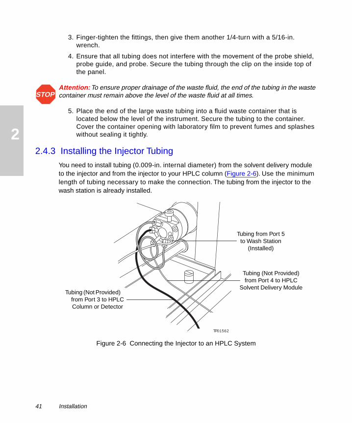
2.4.3 Installing the Injector Tubing
You need to install tubing (0.009-in. internal diameter) from the solvent delivery module to the injector and from the injector to your HPLC column (Figure 2-6). Use the minimum length of tubing necessary to make the connection. The tubing from the injector to the wash station is already installed.
Figure 2-6 Connecting the Injector to an HPLC System
STOP
TP01562
Tubing (Not Provided) from Port 4 to HPLC
Solvent Delivery ModuleTubing (Not Provided)
from Port 3 to HPLC Column or Detector
Tubing from Port 5 to Wash Station
(Installed)
41 Installation

2
To install the injector tubing:
1. Install the tubing for an HPLC column or detector to port 3 of the injector(Figure 2-7).
2. Install the tubing for the solvent delivery module to port 4 of the injector.
Figure 2-7 Injector Tubing Connections
2.5 Making Signal Connections
The 2700 Sample Manager provides a removable connection terminal and a communication port for operation with external devices using digital signal communication. The signal connections you need to make to the 2700 Sample Manager depend on what types of instruments make up your HPLC system, including the Millennium workstation.
This section describes the input/output (I/O) and digital signal connections that you can make from the terminal strip on the back and the RS-232 connector on the left side of the instrument. Figure 2-8 summarizes the signal connections from the 2700 Sample Manager to external devices.
Port 1 Injector Port
Port 2 Sample Loop
Port 3 Outlet to Column or Detector
Port 4 Inlet from HPLC Solvent Delivery Module
Port 5 Sample Loop
Port 6 Waste Fluid
Making Signal Connections 42

2
Figure 2-8 2700 Sample Manager in a Waters HPLC System2.5.1 Installing the Communications Cable
To install the RS-232 communications cable:
1. Insert the male connector into the DB25 receptacle on the left side of the 2700 Sample Manager, then tighten into position.
2. Insert the female connector into the DB9 serial port 1 on your computer, then tighten into position. If the computer does not have a DB9 connector, use a DB25-to-DB9 adapter (not provided).
Note: If a Device Not Found error message appears when you power on the 2700 Sample Manager and your computer has two RS-232 available ports (one mouse port and one general port), connect the cable to serial port 1.
2.5.2 Installing the Signal Cable
To install the signal cable:
1. Remove the terminal strip from the lower-left corner of the back panel.
2. Connect the signal cable to the Channel 1 and Channel 2 connectors on the terminal strip (Figure 2-9). To connect a cable to the terminal strip, insert a small flat-blade screwdriver in the top socket, rotate it 1/4-turn to open the bottom socket, insert the stripped end of the cable into the bottom socket, then remove the screwdriver.
Waters HPLC Module
2700 Sample Manager
Millennium Chromatography
Manager
IEEE-488 Cable
Signal Cable from Terminal Strip
RS-232 Cable
43 Installation

2
Figure 2-9 Connecting the Cable to the Terminal Strip3. Connect the signal cable to the HPLC module (Table 2-2).
Table 2-2 I/O Signals
Connector Number Signal Description
1 – Connects signal cable to appropriate HPLC module in order to provide inject start signal. The 2700 Sample Manager sends the signal automatically upon injection.
2 + Connects signal cable to appropriate HPLC module in order to provide inject start signal. The 2700 Sample Manager sends the signal automatically upon injection.
3 S1 Connects signal cable to HPLC column selection valve.
4 S2 Connects signal cable to HPLC column selection valve.
5 S3 Connects signal cable to HPLC column selection valve.
6 S4 Connects signal cable to HPLC column selection valve.
7 Ground Connects system to ground.
C– + S1 S2 S3 S4 Ground A B
1 2 3 4 5 6 7 8 9 10
Inject Starts
Sockets for Screwdriver
Sockets for Connectors
Signals
Making Signal Connections 44
2
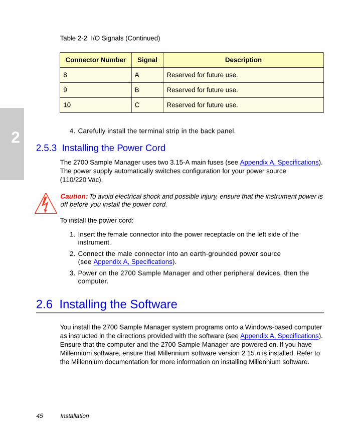
4. Carefully install the terminal strip in the back panel.2.5.3 Installing the Power Cord
The 2700 Sample Manager uses two 3.15-A main fuses (see Appendix A, Specifications). The power supply automatically switches configuration for your power source (110/220 Vac).
Caution: To avoid electrical shock and possible injury, ensure that the instrument power is off before you install the power cord.
To install the power cord:
1. Insert the female connector into the power receptacle on the left side of the instrument.
2. Connect the male connector into an earth-grounded power source (see Appendix A, Specifications).
3. Power on the 2700 Sample Manager and other peripheral devices, then the computer.
2.6 Installing the Software
You install the 2700 Sample Manager system programs onto a Windows-based computer as instructed in the directions provided with the software (see Appendix A, Specifications). Ensure that the computer and the 2700 Sample Manager are powered on. If you have Millennium software, ensure that Millennium software version 2.15.n is installed. Refer to the Millennium documentation for more information on installing Millennium software.
8 A Reserved for future use.
9 B Reserved for future use.
10 C Reserved for future use.
Table 2-2 I/O Signals (Continued)
Connector Number Signal Description
45 Installation
2
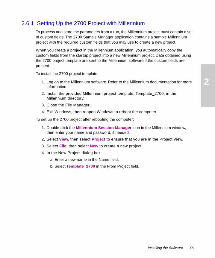
2.6.1 Setting Up the 2700 Project with Millennium
To process and store the parameters from a run, the Millennium project must contain a set of custom fields. The 2700 Sample Manager application contains a sample Millennium project with the required custom fields that you may use to create a new project.
When you create a project in the Millennium application, you automatically copy the custom fields from the startup project into a new Millennium project. Data obtained using the 2700 project template are sent to the Millennium software if the custom fields are present.
To install the 2700 project template:
1. Log on to the Millennium software. Refer to the Millennium documentation for more information.
2. Install the provided Millennium project template, Template_2700, in the Millennium directory.
3. Close the File Manager.
4. Exit Windows, then reopen Windows to reboot the computer.
To set up the 2700 project after rebooting the computer:
1. Double-click the Millennium Session Manager icon in the Millennium window, then enter your name and password, if needed.
2. Select View, then select Project to ensure that you are in the Project View.
3. Select File, then select New to create a new project.
4. In the New Project dialog box:
a. Enter a new name in the Name field.
b. Select Template_2700 in the From Project field.
Installing the Software 46
2
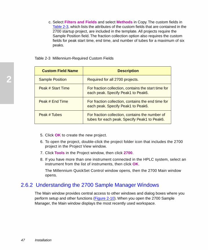
c. Select Filters and Fields and select Methods in Copy. The custom fields in Table 2-3, which lists the attributes of the custom fields that are contained in the 2700 startup project, are included in the template. All projects require the Sample Position field. The fraction collection option also requires the custom fields for peak start time, end time, and number of tubes for a maximum of six peaks.
5. Click OK to create the new project.
6. To open the project, double-click the project folder icon that includes the 2700 project in the Project View window.
7. Click Tools in the Project window, then click 2700.
8. If you have more than one instrument connected in the HPLC system, select an instrument from the list of instruments, then click OK.
The Millennium QuickSet Control window opens, then the 2700 Main window opens.
2.6.2 Understanding the 2700 Sample Manager Windows
The Main window provides central access to other windows and dialog boxes where you perform setup and other functions (Figure 2-10). When you open the 2700 Sample Manager, the Main window displays the most recently used workspace.
Table 2-3 Millennium-Required Custom Fields
Custom Field Name Description
Sample Position Required for all 2700 projects.
Peak # Start Time For fraction collection, contains the start time for each peak. Specify Peak1 to Peak6.
Peak # End Time For fraction collection, contains the end time for each peak. Specify Peak1 to Peak6.
Peak # Tubes For fraction collection, contains the number of tubes for each peak. Specify Peak1 to Peak6.
47 Installation

2
Figure 2-10 Main Window
You can enter and change values in the 2700 Sample Manager windows using the keyboard and the left mouse button. The windows can include error messages, dialog boxes, and other menus and messages containing buttons and fields. Refer to Table 2-4 for specific tasks.
Table 2-4 Entering Information in the 2700 Sample Manager Windows
Task Description
Activate a function Select a button by clicking once.
Select an item from a drop-down menu Click on the arrow next to the box, then click on the name of an item.
Enter data in a field or a data entry box Click in the data field, then type the data.
Change data in a field or a data entry box
Double-click to select the data you want to change, then type the correct data.
Injector Position
Deep Well
Microtiter Plates on Work Table
Microplate A
B D
C E
F
Wash Station
Rinse Port
Shallow Well
Installing the Software 48

2
2.7 Installing the Syringe
The pipetting and pumping system is powered by an integral high-precision single-piston syringe pump. The Startup Kit contains a 500-µL syringe (Waters Part No. 272081). You can install a syringe with a capacity of 250, 500, 1000, or 5000 µL on the syringe pump.
To wet the syringe, manually pull the solvent into the syringe and then dispense it. Wet the syringe with reagent grade solvent that you plan to use for HPLC runs. Do not allow any syringe to run dry more than a few cycles without solvent.
Caution: To avoid possible injury, always keep your hands outside the work table and do not lean over the instrument during operation. Press the Pause button and wait until the instrument pauses whenever you must work in or over the work table.
To install a syringe on the syringe pump:
1. Click Init HW in the Main window. The Initialize Hardware dialog box appears (Figure 2-11).
Select or deselect a check box Click once to select; click again to deselect.
Move through the fields on a window Press the Tab key to move the cursor left to right and top to bottom through the fields on a window. Press Shift and Tab to move the cursor in the reverse direction.
Access Help Click Help in the Main window.
Access information about the 2700 Sample Manager
Click Help in the Main window, then select About in Help.
Table 2-4 Entering Information in the 2700 Sample Manager Windows (Continued)
Task Description
49 Installation

2
Figure 2-11 Initialize Hardware Dialog Box
2. Click Initialize Robot & Pump.
3. Click Change Syringe. The plunger shaft moves to the correct position for installing a syringe.
4. Insert the plunger into the barrel of the syringe (Figure 2-12).
Figure 2-12 Installing a Syringe
TP01
559
Syringe Barrel
Syringe Plunger
Installing the Syringe 50

2
5. When the plunger shaft stops moving, remove the plunger shaft screw from the plunger shaft.
6. Mount the bottom of the syringe plunger on the plunger shaft.
7. Replace the plunger shaft screw on the base of the plunger shaft.
Attention: To avoid stripping the bayonet threads when mounting the syringe barrel on the bottom of the 4-port syringe valve, gently push the syringe barrel upward.
8. Line up the top of the syringe barrel with the bayonet fitting of the valve, then screw the barrel onto the fitting while pushing upward slightly.
2.8 Initializing and Priming
To ensure correct operation of the 2700 Sample Manager, you can initialize the probe and the syringe pump and prime the pumps. Principles of pump operation include the following guidelines:
• Prime the pumps thoroughly with distilled and deionized water when not in use.
• Do not allow the pumps to run dry for more than a few cycles. Do not allow any syringe to run dry more than a few cycles without solvent.
• Wipe up all spills on and around the pumps immediately.
• Use Purge Pump to fill the syringe pump with fresh solvent.
Attention: To avoid precipitating salts, use an intermediate solvent such as distilled and deionized water when you change from buffers to high-organic-content solvents. Refer to Appendix D, Solvent Considerations, for information on solvent miscibility.
2.8.1 Initializing the Probe and Syringe Pump
Use Initialize Robot & Pump to move the syringe pump and the probe assembly, including the probe on the X/Y/Z robotic arm, to the home positions. The home position of the probe corresponds to the coordinate of x = 0, y = 0, z = 0 in the back upper-left corner.
To initialize the probe assembly and the syringe pump:
1. If the Initialize Hardware dialog box is not open, click Init HW in the Main window. The Initialize Hardware dialog box appears (Figure 2-11).
2. Click Initialize Robot & Pump. Wait while the probe moves to the home position, moves to the wash station, then stops.
3. If the probe fails to initialize:
a. Click Reinitialize.
STOP
STOP
51 Installation

2
b. If it fails repeatedly, press the Esc key on the keyboard.
c. Click Init HW in the Main window.
d. Click Initialize Robot & Pump.
2.8.2 Priming the Pumps
Use Prime Pump and Wash On/Wash Off to prime the syringe pump and the wash pump:
• To remove all bubbles from the tubing
• To thoroughly flush the tubing and syringe with solvent
• To change containers or types of solvent
To prime the pumps:
1. If the Initialize Hardware dialog box is not open, click Init HW in the Main window. The Initialize Hardware dialog box appears.
2. Click Initialize Robot & Pump to initialize the probe and the syringe pump.
3. Click Prime Pump to prime the syringe pump and the syringe.
4. If bubbles remain in the syringe or tubing, check to ensure that the valve fittings are tight and the syringe is securely installed, then click Prime Pump.
5. Click Wash On, then wait approximately 10 seconds to prime the wash pump.
6. Click Wash Off to stop priming the wash pump.
7. Inspect the tubing for bubbles, inspect the pumps and tubing for leaks, then correct any problems immediately.
8. Click OK to close the Initialize Hardware dialog box.
2.9 Changing the Sample Loop
The 2700 Sample Manager includes a 20-µL sample loop (Waters Part No. 096224).
Note: To completely fill a sample loop, the instrument requires at least three times the sample loop volume for full loop injections.
To change the sample loop on the injector:
1. Remove the loop by unscrewing both connectors from ports 2 and 5 on the injector, then carefully pulling the loop off the injector (Figure 2-7).
2. Unwrap the new sample loop.
Changing the Sample Loop 52
2
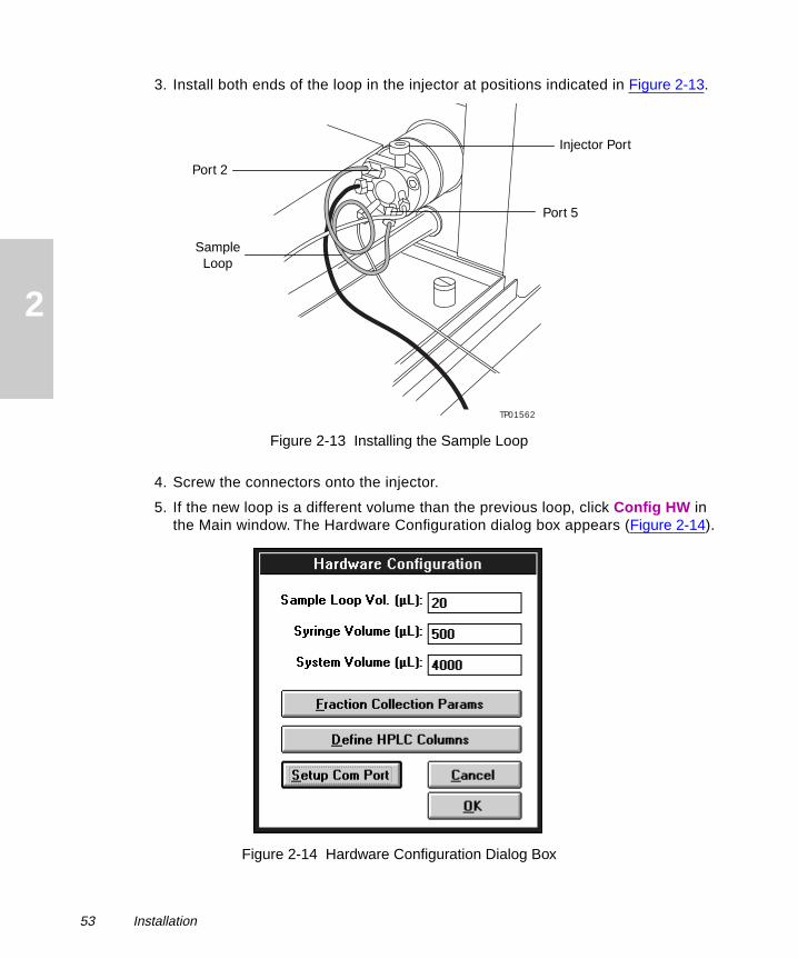
3. Install both ends of the loop in the injector at positions indicated in Figure 2-13.
Figure 2-13 Installing the Sample Loop
4. Screw the connectors onto the injector.
5. If the new loop is a different volume than the previous loop, click Config HW in the Main window. The Hardware Configuration dialog box appears (Figure 2-14).
Figure 2-14 Hardware Configuration Dialog Box
TP01562
Sample Loop
Injector Port
Port 2
Port 5
53 Installation

2
6. Double-click Sample Loop Vol.
7. Type the new sample loop volume in microliters, then click OK.
2.10 Installing the Shields
Shields protect you from injury during operation. The Startup Kit contains the left shield (Waters Part No. 272053), the right shield (Waters Part No. 272066), and the probe shield (Waters Part No. 272054).
To install the shields:
1. Remove the paper from the right and left side shields, then clean all three shields with isopropyl alcohol and lint-free cloths.
2. Insert the right shield into the top and bottom grooves on the right side of the work surface (Figure 2-15). The right shield has a hole at the bottom for injector tubing.
Figure 2-15 Installing the Shields
3. Insert the HPLC column tubing from the injector through the hole in the right shield, then connect the tubing to an HPLC column.
TP01554
Left Shield
Right Shield
Probe Shield
Tubing Hole
Installing the Shields 54
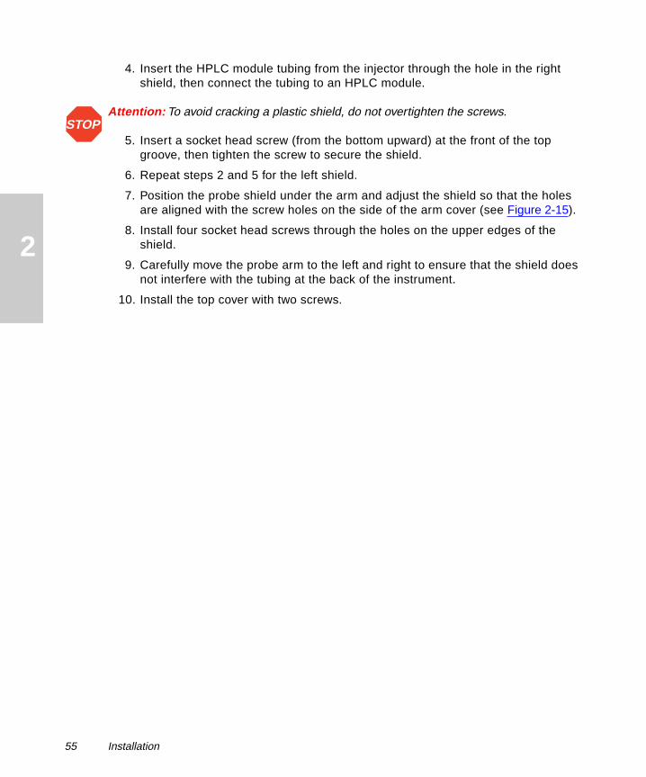
2
4. Insert the HPLC module tubing from the injector through the hole in the right shield, then connect the tubing to an HPLC module.
Attention: To avoid cracking a plastic shield, do not overtighten the screws.
5. Insert a socket head screw (from the bottom upward) at the front of the top groove, then tighten the screw to secure the shield.
6. Repeat steps 2 and 5 for the left shield.
7. Position the probe shield under the arm and adjust the shield so that the holes are aligned with the screw holes on the side of the arm cover (see Figure 2-15).
8. Install four socket head screws through the holes on the upper edges of the shield.
9. Carefully move the probe arm to the left and right to ensure that the shield does not interfere with the tubing at the back of the instrument.
10. Install the top cover with two screws.
STOP
55 Installation

3
3Operation
This chapter describes how to operate the Waters 2700 Sample Manager with the Millennium Chromatography Manager or in stand-alone mode (Figure 3-1).
Figure 3-1 Operating the 2700 Sample Manager
3.1 Starting the Operation
You start the operation of the 2700 Sample Manager by:
• Opening the 2700 software from the Tools menu in the Millennium Project window if you are using Millennium software
• Opening the 2700 software directly if you are using stand-alone mode
Start Operation
Set Up a Workspace
Perform a Run
Set Up a Sample Group
Open the Project in Millennium
Open the 2700 Program
Finish Operation
Using Millennium?
Yes
No
Configure the Hardware
Starting the Operation 56

3
3.1.1 Opening the Project with Millennium
To start routine operation of the 2700 Sample Manager with the Millennium software, open the project template from the Millennium Session Manager:
1. Double-click the project folder icon that includes the 2700 project in the Project View window.
2. Click Tools in the Project window, then click 2700.
3. If you have more than one instrument connected in the HPLC system, select an instrument from the list of instruments, then click OK.
The Millennium QuickSet Control window opens, then the 2700 Main window opens.
3.1.2 Opening the Program in Stand-Alone Mode
To start routine operation of the 2700 Sample Manager in stand-alone mode:
1. Double-click the 2700 Main icon in the 2700 window in the Program Manager.
2. Click Yes to open the 2700 Main window without Millennium.
The 2700 Main window opens.
3.2 Configuring the Hardware
Configuring the hardware involves entering or changing the sample loop volume, syringe volume, system volume, and information about the HPLC columns that are connected to the instrument.
The system volume is used to automatically calculate the amount of fluid needed to prime or purge the system. System tubing consists of the probe tubing, the interconnect tubing from the syringe to the manifold block, and the reagent tubing from the solvent container to the syringe. The volume is estimated from the length and the internal diameter of the tubing.
Automated column selection of up to six columns requires installation of an optional column switching valve. If no switching valve is installed, the description of names in the HPLC Column Parameter Setup dialog box is for informational purposes only.
To configure the hardware:
1. Click Config HW in the Main window. The Hardware Configuration dialog box appears (Figure 3-2).
57 Operation

3
Figure 3-2 Hardware Configuration Dialog Box
Note: To completely fill a sample loop, the instrument requires at least three times the sample loop volume for full loop injections.
2. If your sample loop volume differs from the default value, enter the sample loop volume in µL.
3. If your syringe volume is different from the default value, enter the syringe volume in µL.
4. If your system volume is different from the default value, enter the chromatographic system volume in µL. The default system volume is 4000 µL for the tubing that is provided. If you use different tubing, adjust the system volume accordingly.
5. Click Define HPLC Columns. The HPLC Column Parameter Setup dialog box appears (Figure 3-3).
Configuring the Hardware 58

3
Figure 3-3 HPLC Column Parameter Setup Dialog Box
6. Enter the appropriate values in the fields for each column (Table 3-1).
7. Click OK to save the column parameter setup.
8. Click OK to save the hardware configuration.
Table 3-1 HPLC Column Parameters
Parameter Description
Description You can change a column name by selecting the name and typing a new name (up to 12 characters). You can install up to six columns on the system.
Equilibration You can change the number of minutes that each column should equilibrate before injection.
Pattern You can change a switching logic pattern (Pattern 1, 2, 3, 4) of the HPLC column switching valve; corresponds to the switches S1, S2, S3, and S4 on the back panel.
59 Operation

3
3.3 Setting Up Workspaces
To set up the workspaces:
• Select a workspace
• Create a customized workspace
• Check the probe calibrations
3.3.1 Selecting a Workspace
The 2700 Sample Manager uses rectangular or square racks or trays, some with regularly spaced holes. You position the racks and trays horizontally in the drip tray on the instrument. The workspace in the Main window designates the arrangement and the types of racks and trays that hold the test tubes, HPLC vials, Eppendorf tubes, or microtiter plates.
To select a workspace:
1. Select the WorkSpace drop-down list in the Main window (Figure 3-4).
Figure 3-4 Selecting a Workspace
2. Select the name of a workspace for your sample racks. The Main window displays the arrangement of racks for the selected workspace (Table 3-2).
Table 3-2 Default Workspaces
Workspace Sample Container Rack Set
2SQUARE HPLC vials (13 mm)
Test tubes (13 mm)
Eppendorf tubes (1.5 mL)
SquareSet (Left)
SquareSet (Right)
HEX 96-well or 384-well microtiter plates 6MTP
Setting Up Workspaces 60

3
3. To change a tray type, select Workspace Editor in the Main window. The Workspace Editor window appears (Figure 3-5). The probe moves to the coordinates of (0, 0, 0) at the back-left corner of the work table.
Figure 3-5 Workspace Editor Window
4. Click a tray selection button in the Workspace Editor window. The Select a Rack dialog box appears.
5. Select a rack in the Select a Rack dialog box (see Table 3-2).
6. Click Select in the Select a Rack dialog box.
7. Click Quit to close the Select a Rack dialog box.
8. Repeat steps 4 through 7 for each tray that you want to change.
9. Select File, then select Save in the Workspace Editor window.
QUADMTP 96-well or 384-well microtiter plates, both standard and deep wells
2MTP (Left)
2MTP (Right)
Table 3-2 Default Workspaces (Continued)
Workspace Sample Container Rack Set
Tray Selection Button
Reference Position
61 Operation

3
10. Type a unique name with eight characters or less, then click OK.
11. Click Exit to close the Workspace Editor window.
3.3.2 Creating a Customized Workspace
You can create up to 25 workspaces for your laboratory to designate the arrangement and the types of racks that hold sample containers. The racks are specific for the sample containers, including standard HPLC vials, test tubes, Eppendorf tubes, or microtiter plates (Table 3-2). You can start with a default workspace (see Section 3.3.1, Selecting a Workspace).
Attention: The x-, y-, and z-coordinates of the probe must be calibrated against the two reference positions for each rack on each workspace and against the fixed positions before first use (see Section 3.3.3, Checking the Probe Calibrations).
To create a workspace:
1. Select Workspace Editor in the Main window. The probe moves to the coordinates of (0, 0, 0) at the back-left corner of the work table.
2. Click Place Rack Set. The Select & Place Rack Sets dialog box appears (Figure 3-6).
Figure 3-6 Select & Place Rack Sets Dialog Box
3. To create arrangements of racks on the work table, select a rack set in the Select & Place Rack Sets dialog box, then click Place.
Note: If you select 6MTP, the workspace on the Main window is complete. The 6MTP rack accommodates standard, 96-well microtiter plates or high-density, 384-well microtiter plates.
STOP
Setting Up Workspaces 62

3
4. If you select 2MTP(Left) or SquareSet(Left), select either 2MTP(Right) or SquareSet(Right), then click Place to complete the workspace.
5. Click Quit to close the Select & Place Rack Sets dialog box.
6. Select File, then select Save As in the Workspace Editor window.
7. Type a unique name with eight characters or less and a .cfg extension, then click OK. To avoid overwriting a current workspace, ensure that you enter a new name.
8. You can change the tray (see Section 3.3.1, Selecting a Workspace).
9. Check the probe coordinates for the workspace (see Section 3.3.3, Checking the Probe Calibrations). The x-, y-, and z-coordinates of the probe must be calibrated against the reference positions of the racks and the fixed positions before first use.
10. Click Exit to close the Workspace Editor window.
3.3.3 Checking the Probe Calibrations
The probe requires checking before first use to ensure that it is calibrated to all reference positions of the containers on each workspace. You check the calibration of the probe coordinates relative to each sample rack and container. You also check the probe calibration to the fixed positions at the injector and the wash station for each workspace.
Note: Default values may not be optimized for any particular container and may require slight adjustment.
Calibrating the Sample Racks and Containers
To check the calibration of the probe to a container:
1. Ensure that the correct racks and containers are installed by comparing the actual racks and containers on the instrument to the racks and containers in the Main window.
Caution: To avoid possible injury, always keep your hands outside the work table and do not lean over the instrument during operation. Press the Pause button and wait until the instrument pauses whenever you must work in or over the work table.
2. Select Workspace Editor in the Main window. The probe moves to the coordinates of (0, 0, 0) at the back-left corner of the work table. The Workspace Editor window appears, showing the reference positions as large red circles in the upper-left and lower-right corner of each container (Figure 3-7).
63 Operation

3
Figure 3-7 Reference Positions for Sample Racks and Containers
3. Select a reference position on a rack in the Workspace Editor window. Clicking a position directs the probe to move to the position.
4. Click Calibrate in the Workspace Editor window.
5. Center the probe in the x- (left to right) and y- (front to back) directions over the reference position:
a. Move the probe to the center of the position using the arrow keys on the keyboard while visually inspecting the probe (Table 3-3).
Table 3-3 Using the Keyboard to Calibrate the Probe
Key Function
Arrow Move the arm in the x- (left to right) and y- (front to back) directions.
Cursor and Arrow Move the arm faster.
Ctrl and Arrow Move the arm in single steps.
Container Reference Positions
Fixed Reference Positions
Container Reference Positions
Container Reference Positions
Container Reference Positions
Container Reference Positions
Container Reference Positions
Setting Up Workspaces 64

3
Attention: To avoid possible probe damage, keep the tip of the probe at least 0.2 in. (0.5 cm) above the top surface of the rack.
b. Carefully move the probe downward to 0.2 in. (0.5 cm) above the surface of the container using the PgDn key on the keyboard while visually inspecting the probe.
c. Ensure that the probe tip is at the exact center of the position.
6. Carefully move the probe downward to the maximum depth in the container (Zmax) using the PgDn key on the keyboard while visually inspecting the probe (Figure 3-8 and Table 3-4).
Figure 3-8 Checking the Probe Calibrations in the Z-Direction
PgUp and PgDn Move the arm vertically (z-direction).
To raise the probe, subtract 2-step to 5-step increments from the value in the appropriate Z field, then click the >> button.
To lower the probe, add 2-step to 5-step increments to the value in the appropriate Z field, then click the >> button.
Table 3-3 Using the Keyboard to Calibrate the Probe (Continued)
Key Function
STOP
ZtravelZstartZdisp
Sample Level
Zmax
65 Operation

3
7. Click the reference position to open the Calibration Coordinates dialog box (Figure 3-9). The banner area displays the current coordinates of the probe arm.
Figure 3-9 Calibration Coordinates Dialog Box for Containers
Table 3-4 Evaluating the Z-Direction Values
Position Description
Zmax The maximum usable depth of the probe tip in the container or at the fixed position. The Zmax can be designated as any position from just below the surface of the liquid to the inside bottom of the container. The practical limit for Zmax is usually 0.5 mm to 1.0 mm or 5 to 10 steps above the bottom of the container. The Zmax determines the maximum amount of sample that can be drawn from the container.
Zdisp The height at which the probe tip dispenses fluid. The Zdisp value is the same as the Zmax value.
Zstart The top of the container or of the fixed position (injector and wash stations).
Ztravel The safe traveling height of the probe tip over the container; approximately 0.4 in. (1.0 cm) above the rim of the container; only used when calibrating the probe to the containers. Use the same Ztravel height for all racks of similar height.
Zpos The height of the probe in the fixed positions; only used when calibrating the probe to the fixed positions. The Zpos value is the same as the Zmax value.
Setting Up Workspaces 66

3
8. Click the X & Y > button to enter the coordinates.
9. Enter the z-coordinates for the reference position:
a. Click the Zmax > button to enter the current z-coordinate as the Zmax.
b. Click the Zdisp > button to enter the current z-coordinate as the Zdisp.
c. Enter a value in the Zstart > field at least 100 steps less than the Zmax, then click the Zstart > button.
d. Enter a value in the Ztravel > field approximately 0.4 in. (1.0 cm) above the rim of the container, then click the Ztravel > button.
10. Save the values:
a. Click Save in the Calibration Coordinates dialog box.
b. Click Quit in the Calibration Coordinates dialog box.
c. Click End Cal in the Workspace Editor window.
11. Repeat steps 3 through 10 for each reference position on containers in the Workspace Editor window (see Figure 3-7).
Calibrating the Injector Position
To calibrate the probe to the injector:
1. Select the injector reference position in the Workspace Editor window.
2. Click Calibrate in the Workspace Editor window.
3. Center the probe in the x- (left to right) and y- (front to back) directions:
a. Move the probe to the center of the port using the arrow keys on the keyboard while visually inspecting the probe.
Note: Ensure that the probe tip is at the exact center of the port.
b. Carefully move the probe downward until it touches the surface of the injector port using the PgDn key on the keyboard while visually inspecting the probe.
67 Operation

3
4. Click the reference position to open the Calibration Coordinates dialog box (Figure 3-10). The banner area displays the current coordinates of the probe arm.
Figure 3-10 Calibration Coordinates Dialog Box for Fixed Positions
5. Click the X & Y > button to enter the x- and y-coordinates.
6. Enter the z-coordinates for the reference position:
a. Click the Zstart > button to enter the current z-coordinate as the Zstart.
b. Enter a value in the Zmax > field that is at least 60 steps greater than the Zstart coordinate, then click the Zmax > button.
c. Enter a value in the Zdisp > field that is at least 60 steps greater than the Zstart coordinate, then click the Zdisp > button.
d. Enter a value in the Zpos > field that is at least 60 steps greater than the Zstart coordinate, then click the Zpos > button.
7. Save the coordinates:
a. Click Save in the Calibration Coordinates dialog box.
b. Click Quit in the Calibration Coordinates dialog box.
c. Click End Cal in the Workspace Editor window.
Calibrating the Wash Station Positions
To calibrate the probe to the three wash station positions:
1. Select a wash station position in the Workspace Editor window.
2. Click Calibrate in the Workspace Editor window.
3. Center the probe in the x- (left to right) and y- (front to back) directions:
a. Move the probe to the center of the port using the arrow keys on the keyboard while visually inspecting the probe.
Setting Up Workspaces 68

3
b. Carefully move the probe downward to 0.2 in. (0.5 cm) above the surface of the port using the PgDn key on the keyboard while visually inspecting the probe.
c. Ensure that the probe tip is at the exact center of the port.
4. Click the reference position to open the Calibration Coordinates dialog box (Figure 3-10). The banner area displays the current coordinates of the probe arm.
5. Click the X & Y > button to enter the coordinates.
6. Enter the z-coordinates for the port (Table 3-5):
a. Enter a value in the Zmax > field, then click the Zmax > button.
b. Enter a value in the Zdisp > field, then click the Zdisp > button.
c. Enter a value in the Zpos > field, then click the Zpos > button.
d. Enter 700 in the Zstart > field, then click the Zstart > button.
7. Save the coordinates:
a. Click Save in the Calibration Coordinates dialog box.
b. Click Quit in the Calibration Coordinates dialog box.
c. Click End Cal in the Workspace Editor window.
8. Repeat steps 1 through 7 for the fixed reference positions at the wash station.
Saving Probe Calibrations
To save the probe calibrations:
1. Ensure that calibration is complete before performing an injection by verifying all probe positions for the workspace. Click each reference position in turn and visually observe the probe as it travels to each reference position.
Table 3-5 Recommended Z-Coordinates for Wash Station Positions
Fixed PositionZmax, Zdisp, Zpos
CoordinatesZstart Coordinate
Shallow wash station (back port)
1150 700
Waste station (middle port) 1600 700
Deep wash station (front port) 1550 700
69 Operation

3
2. Click Exit to close the Workspace Editor window.
3. Click Yes to save the probe calibrations.
4. Click Init HW, then click Initialize Robot & Pump.
5. Click OK to close the Initialize Hardware dialog box.
3.4 Setting Up Sample Groups
A sample group is a pattern of samples in the racks on the workspace and the order in which the system runs the selected samples. You can create a sample group at any time and save it, or you can create a sample group when you are ready to run samples. You create the sample groups to specify the required order in which the system runs the samples. You can create and save some or all workspaces and sample groups, depending upon the available storage space.
To create a sample group for a workspace:
1. Select Sample Group Editor in the Main window. The Sample Group Editor window appears (Figure 3-11).
Setting Up Sample Groups 70

3
Figure 3-11 Sample Group Editor Window2. Click a button on the right side to designate the sampling order (Figure 3-12).
Figure 3-12 Sampling Order
From Left to Right, Then Back to Front
From Back to Front, Then Left to Right
From Left to Right, Then Right to Left
From Back to Front, Then Front to Back
Zoom Icon to Magnify the Sample Group
Reduce Icon to View the Entire Sample Group
71 Operation

3
3. Create a sample group (Table 3-6).
4. Click the Zoom icon, then click near but not on a position to check the order of samples that you selected (Figure 3-13). Clicking directly on a position changes it from selected to deselected, or from deselected to selected.
Table 3-6 Creating and Editing a Sample Group
Goal Activity
To designate the order that the instrument will run the samples
Select the sampling order (buttons on right side of window).
To enlarge the window so that you can check the scheduled order of samples
Click the magnifying glass icon with the plus sign, then click near but not on a position.
To view the entire rack (when you are in Zoom mode)
Click the magnifying glass icon with the minus sign, then click near but not on a position.
To select a group of sample positions Drag the boxed cursor to draw a rectangle around a group.
To select a single sample in the rack Click the position once to select a sample.
To deselect and delete a selected sample from the sample group
Click the selected sample.
To deselect and delete multiple samples from the sample group
Drag the boxed cursor to draw a rectangle around the group of selected samples.
To clear all positions and start over Click Clr Selections.
To delete the sample group Click Delete This Grp.
To delete all sample groups Click Delete All Grps.
Setting Up Sample Groups 72

3
Figure 3-13 Sample Group Editor Zoom Dialog Box
5. Click the reduce icon to close the zoom view.
6. To save the sample group, click Save Grp As. Type a name for the set using eight characters or less, then click OK.
7. Click Quit Editor to close the Sample Group Editor window.
3.5 Running a Method
To run a method, you use the Main window and the Run window to perform most routine operating tasks for the Waters 2700 Sample Manager with the Millennium Chromatography Manager or in stand-alone mode (Figure 3-14).
1 2 3 4 5 6 7 8 9 10 11 12
A
B
C
D
E
F
G
H
73 Operation
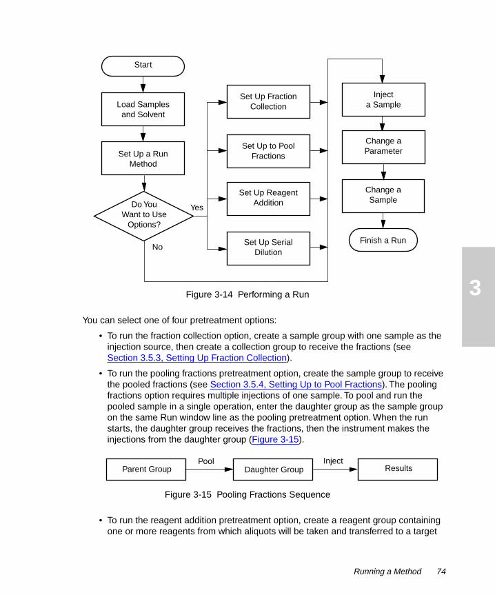
3
Figure 3-14 Performing a RunYou can select one of four pretreatment options:
• To run the fraction collection option, create a sample group with one sample as the injection source, then create a collection group to receive the fractions (see Section 3.5.3, Setting Up Fraction Collection).
• To run the pooling fractions pretreatment option, create the sample group to receive the pooled fractions (see Section 3.5.4, Setting Up to Pool Fractions). The pooling fractions option requires multiple injections of one sample. To pool and run the pooled sample in a single operation, enter the daughter group as the sample group on the same Run window line as the pooling pretreatment option. When the run starts, the daughter group receives the fractions, then the instrument makes the injections from the daughter group (Figure 3-15).
Figure 3-15 Pooling Fractions Sequence
• To run the reagent addition pretreatment option, create a reagent group containing one or more reagents from which aliquots will be taken and transferred to a target
Start
Change a Parameter
Injecta Sample
Set Up a Run Method
Change a Sample
Load Samples and Solvent
Finish a Run
Do YouWant to Use
Options?
Yes
No
Set Up Reagent Addition
Set Up Fraction Collection
Set Up Serial Dilution
Set Up to Pool Fractions
Parent Group Daughter GroupInjectPool
Results
Running a Method 74

3
group (see Section 3.5.5, Setting Up Reagent Addition). When the run starts, the target group receives the reagents, then the instrument makes the injections from the target group (Figure 3-16).
Figure 3-16 Reagent Addition Sequence
• To run the serial dilution pretreatment option, select one sample in the sample group as the parent group and a series of tubes to receive the dilutions as the daughter group (see Section 3.5.6, Setting Up Serial Dilution). When the run starts, the daughter group receives the dilutions, then the instrument makes the injections from the daughter group (Figure 3-17).
Figure 3-17 Serial Dilution Sequence
3.5.1 Preparing for a Run
To prepare for a run, you load the sample containers into the racks, load the racks onto the work table, and check the solvents.
Loading Samples
The instrument has a cap-piercing probe that allows you to keep standard silicone-coated PTFE septa on the HPLC vials. Ensure that the caps and coverings on your sample containers can be reliably pierced without probe damage or movement of the container from its position. Remove other types of caps and septa from the sample containers because they may damage the probe.
Attention: To prevent damage to the probe, ensure that microtiter plates are correctly installed by snapping them completely down onto the racks. Ensure that you install the deep-well microtiter plates in the racks when you select the deep wells for the work table, as directed by the Workspace window. Remove all caps and septa from the sample containers except standard silicone-coated PTFE septa on HPLC vials because other types may damage the probe.
Reagent Group Target GroupInject
Add Reagents
Results
Parent Group Daughter GroupInjectDilute
Results
STOP
75 Operation

3
1. Load the samples in the appropriate racks according to the workspace that is displayed in the Main window. Use the Main window to help you load the microtiter plates, HPLC vials, Eppendorf tubes, or test tubes into the racks.
2. Install the racks on the work table:
a. Place the back of the rack against the drip tray while holding the handle toward the front.
b. Place the two holes on bottom front of the rack over the locator guides at the front of the drip tray.
3. Ensure that the racks on the work table match the arrangement of racks in the workspace on the Main window (see Section 3.3, Setting Up Workspaces). The system assigns the rack order from the back-left corner forward and from left to right.
Checking Solvents
Check the solvents before starting a run:
• Ensure that all solvent containers contain the correct solvent for your applications.
• Follow standard laboratory practice to filter the solvents before use.
• Refill solvent containers and filter solvent if needed.
• Check and empty the fluid waste container if needed.
• Do not allow any syringe to run dry more than a few cycles without solvent.
Attention: To avoid precipitating salts, use an intermediate solvent such as distilled and deionized water when you change from buffers to high-organic-content solvents. Refer to Appendix D, Solvent Considerations, for information on solvent miscibility.
If you change containers or types of solvent, prime the syringe pump and the wash pump by thoroughly flushing with solvent (see Section 2.8.2, Priming the Pumps), and ensure that the tubing is free of air bubbles.
3.5.2 Performing a Run
To perform a run:
1. Click Run Method in the Main window. The Run window appears (Figure 3-18).
• If the Millennium QuickSet Control window is open, the project and system names are filled in from the Millennium software and the selected Millennium method set appears in the Millen. Method Set field.
• If the 2700 Sample Manager is operating in stand-alone mode, you can type the project name in the Project field and the system name in the System field.
STOP
Running a Method 76

3
Figure 3-18 Run Window
2. Select a sample group from the Sample Group drop-down list box in the Main window or create a new group (see Section 3.4, Setting Up Sample Groups).
3. Enter the values in the Run window for the parameters as shown in Table 3-7.
Table 3-7 Entering Run Window Values
ParameterDefault Value
Values for Parameter
Sample Group None Sample groups created in the Sample Group Editor window for the selected workspace
# of Inj’s 1 1 to 99
µL Sample 20 Installed sample loop defines range of possible values
µL Rinse 250 If greater than 800 µL, instrument uses the wash pump; if less than or equal to 800 µL, instrument uses the syringe pump
Millen. Method Set
None Filled in from Millennium Method Set
Runtime, min 5 0.1 to 654 minutes per injection
77 Operation

3
4. If you do not need the fraction collection or pretreatment options, continue with Section 3.5.7, Injecting the Samples.
3.5.3 Setting Up Fraction Collection
You can define fraction collection for one sample in a run. You can collect up to six peaks for the sample. The peaks you want to collect are called zones. A zone includes a series of wells or tubes to collect fractions for an anticipated area of a peak.
The 2700 Sample Manager uses embedded program commands instead of inject signals to perform fraction collection.
To set up fraction collection:
1. Ensure that the sample group contains one sample (Figure 3-19).
Figure 3-19 Creating a Sample Group for Fraction Collection
HPLC Column None Your names of up to six HPLC columns
Pre-treatment None Pooling (see Section 3.5.4, Setting Up to Pool Fractions)
Reagadd (see Section 3.5.5, Setting Up Reagent Addition)
Serdilut (see Section 3.5.6, Setting Up Serial Dilution)
FC None Yes or No (see Section 3.5.3, Setting Up Fraction Collection)
Table 3-7 Entering Run Window Values (Continued)
ParameterDefault Value
Values for Parameter
Running a Method 78

3
2. When you select Yes in the FC field of the Run window, the Fraction Collection Setup dialog box opens (Figure 3-20).
Figure 3-20 Fraction Collection Setup Dialog Box
Note: Zones must be in nonoverlapping chronological order.
3. Select a zone.
4. You can enter a name.
5. Enter a start time in minutes.
6. Enter a retention time in minutes.
7. Enter an end time in minutes that is greater than the retention time.
8. Repeat steps 3 through 7 for each zone.
9. Create the collection group for the fractions to be collected:
a. Click Collection Group, then click New Group. The Sample Group Editor window appears.
b. Select the tubes to receive the fractions (Figure 3-21). The number of tubes and minimum volume in µL are automatically calculated. The collection group must contain at least the number of tubes in the Total: # Tubes field. In the example, the samples are numbered from left to right, then right to left.
79 Operation

3
Figure 3-21 Creating a Collection Group
c. Click Save Grp As, name the group, and click OK. The Fraction Collection Setup dialog box reappears with the new name in the Collection Group field.
10. Enter the pump flow rate in mL/min from the HPLC system that you are using.
11. You can enter either:
• Slice time in the Slice (sec) field
• Number of tubes in the # Tubes field
Note: You can click Distribute Proportionately to distribute the number of tubes proportionately among the peaks. The slice time and the number of tubes are automatically calculated.
12. Click OK to save the changes and to close the Fraction Collection Setup dialog box.
13. Continue with Section 3.5.7, Injecting the Samples.
3.5.4 Setting Up to Pool Fractions
Use the Pooling Fractions pretreatment option to pool fractions that were collected from multiple injections of a sample. You can collect fractions on the 2700 Sample Manager (see Section 3.5.3, Setting Up Fraction Collection) or on an external fraction collector.
To set up pooling fractions from a fraction collection:
1. Create a daughter group in the Sample Group field in the Run window to receive the pooled fractions.
2. Open the drop-down list in the Pre-treatment column in the Run window (Figure 3-22).
Running a Method 80

3
Figure 3-22 Selecting Pretreatment Options
3. Select POOLING. The Pooling Pretreatment Routine dialog box appears (Figure 3-23).
Figure 3-23 Pooling Pretreatment Routine Dialog Box
4. Create a parent group in the Parent Group field. The parent group contains the fractions to be pooled from the collection group in a fraction collection run. Figure 3-24 shows an example of a collection group for three injections, two peaks, and four fractions collected per injection. The samples are numbered from left to right, then right to left.
81 Operation

3
Figure 3-24 Contents of a Collection Group
a. Select New Group in the Parent Group list. The Sample Group Editor window appears.
b. Click a sampling order button to designate the sampling order (Figure 3-25).
Figure 3-25 Sampling Order Buttons
c. Select the wells that contain the fractions to be pooled. Figure 3-26 shows an example of a parent group that pools fractions two and three of peak one for three injections.
Figure 3-26 Creating a Parent Group for Pooling Fractions
d. Click Save Grp As, name the group, and click OK.
5. Select the same daughter group in the Pooling Pretreatment Routine dialog box as the sample group in the Run window. The daughter group is injected after pretreatment.
6. Enter the transfer volume in µL in the Transfer Vol. µL field. The instrument transfers the same volume from each well in the parent group to the daughter group.
7. Enter the tubes per fraction in the Tubes per Fraction field.
Injection 1, Peak 1, Fractions 1 through 4
Injection 3, Peak 1, Fractions 1 through 4
Injection 2, Peak 1, Fractions 1 through 4
Running a Method 82

3
8. Enter the wash time in seconds in the Wash Time Sec field. The probe is washed after it aspirates and dispenses fluid.
9. Click OK to save the changes and to close the Pooling Pretreatment Routine dialog box.
10. Continue with Section 3.5.7, Injecting the Samples.
3.5.5 Setting Up Reagent Addition
Use the Reagadd pretreatment option to add reagents to samples, to mix the samples, then to inject the samples. Place the reagents in sample containers in a rack on the work table. You can add up to four reagents to a sample or a series of samples (the target group).
Note: All samples in the target group receive the same pretreatment (volume added, number of mix cycles, wash, and incubation times) before injection starts. The instrument adds all reagents to all samples in the group before starting the first injection. To maintain consistent total incubation times for a series of samples, you can set up each run separately in the Run window.
To set up reagent addition:
1. Open the drop-down list in the Pre-treatment column in the Run window.
2. Select REAGADD. The Reagadd Pretreatment Routine dialog box appears (Figure 3-27).
83 Operation
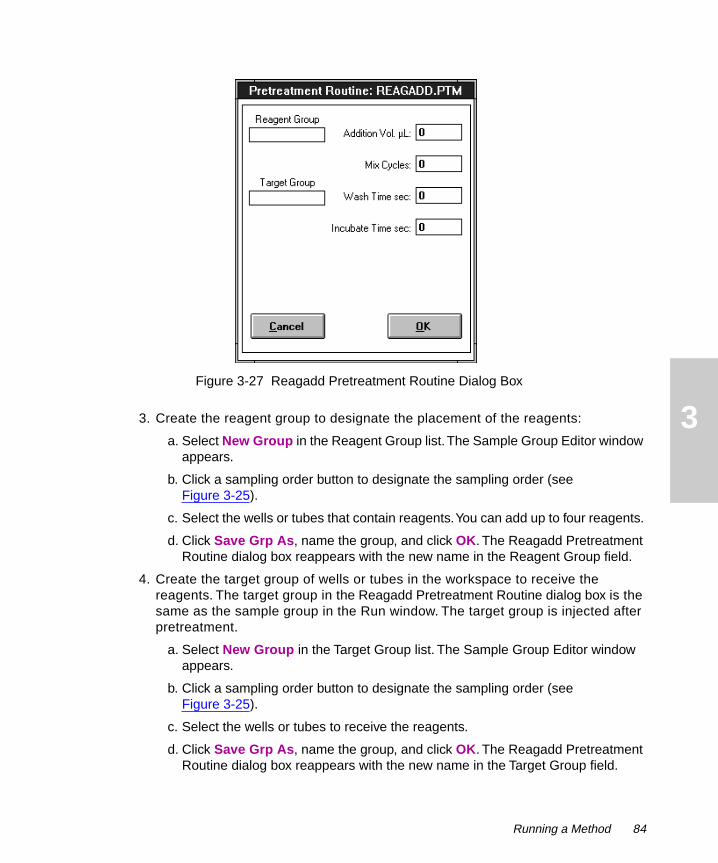
3
Figure 3-27 Reagadd Pretreatment Routine Dialog Box3. Create the reagent group to designate the placement of the reagents:
a. Select New Group in the Reagent Group list. The Sample Group Editor window appears.
b. Click a sampling order button to designate the sampling order (see Figure 3-25).
c. Select the wells or tubes that contain reagents. You can add up to four reagents.
d. Click Save Grp As, name the group, and click OK. The Reagadd Pretreatment Routine dialog box reappears with the new name in the Reagent Group field.
4. Create the target group of wells or tubes in the workspace to receive the reagents. The target group in the Reagadd Pretreatment Routine dialog box is the same as the sample group in the Run window. The target group is injected after pretreatment.
a. Select New Group in the Target Group list. The Sample Group Editor window appears.
b. Click a sampling order button to designate the sampling order (see Figure 3-25).
c. Select the wells or tubes to receive the reagents.
d. Click Save Grp As, name the group, and click OK. The Reagadd Pretreatment Routine dialog box reappears with the new name in the Target Group field.
Running a Method 84

3
5. Enter the reagent volume to be added in µL in the Addition Vol. µL field. The instrument adds the same volume of each reagent to each sample in the target group.
6. Enter the number of mix cycles in the Mix Cycles field. The instrument aspirates and dispenses the contents of the well once during each mix cycle. You can specify up to 10 mix cycles.
7. Enter the wash time in seconds in the Wash Time Sec field. The probe is washed after it aspirates and dispenses fluid.
8. Enter the incubate time in seconds in the Incubate Time Sec field.
9. Click OK to save the changes and to close the Reagadd Pretreatment Routine dialog box.
10. Ensure that the sample group in the Run window is the same as the target group in the Reagadd Pretreatment Routine dialog box.
11. Continue with Section 3.5.7, Injecting the Samples.
3.5.6 Setting Up Serial Dilution
Use the Serdilut pretreatment option to perform serial dilution of a sample, then to inject the diluted samples.
To set up serial dilution:
1. Open the drop-down list in the Pre-treatment column in the Run window.
2. Select SERDILUT. The Serdilut Pretreatment Routine dialog box appears (Figure 3-28).
85 Operation

3
Figure 3-28 Serdilut Pretreatment Routine Dialog Box
3. Create the parent group for the sample to be serially diluted:
a. Select New Group in the Parent Group list. The Sample Group Editor window appears.
b. Select the sample to be serially diluted, such as a well on the left side of the microplate. You can perform one set of serial dilutions at a time.
c. Click Save Grp As, name the group, and click OK. The Serdilut Pretreatment Routine dialog box reappears with the new name in the Parent Group field.
4. Create the daughter group to receive the serial dilutions. The daughter group in the Serdilut Pretreatment Routine dialog box is the same as the sample group in the Run window. The daughter group is injected after pretreatment.
a. Select New Group in the Daughter Group list. The Sample Group Editor window appears.
b. Click the first sampling order button to designate the sampling order (see Figure 3-25).
c. Select the wells or tubes to receive the serial dilutions, such as an array of wells or tubes to the right of the undiluted sample. You can serially dilute a sample up to five times. Ensure that you select at least as many wells or tubes as the number of serial dilutions.
d. Click Save Grp As, name the group, and click OK. The Serdilut Pretreatment Routine dialog box reappears with the new name in the Daughter Group field.
Running a Method 86

3
5. Enter the transfer volume in µL in the Transfer Vol. µL field to specify the volume of sample to be transferred for every dilution.
6. Enter the number of mix cycles in the Mix Cycles field.
7. Enter the wash time in seconds in the Wash Time Sec field. The probe is washed after it aspirates and dispenses fluid.
8. Enter the number of serial dilutions for the sample in the No. Dilutions field. You can serially dilute a sample up to five times. The number of wells or tubes in the daughter group must at least match the number of serial dilutions.
9. Enter the diluent volume in µL in the Diluent Vol. µL field. For example, for a series of 1:5 dilutions with a transfer volume of 10 µL, enter a diluent volume of 40 µL.
10. Click OK to save the changes and to close the Serdilut Pretreatment Routine dialog box.
11. Ensure that the sample group in the Run window is the same as the daughter group in the Serdilut Pretreatment Routine dialog box.
12. Continue with Section 3.5.7, Injecting the Samples.
3.5.7 Injecting the Samples
You inject the samples after entering the run method and selecting any options in the Run window.
During an injection, the 2700 Sample Manager aspirates the first sample, dispenses the sample into the injector, washes the probe, and repeats the process for each sample in the sample group. Table 3-8 describes the sequence of events if a pretreatment option is selected.
Table 3-8 Sequence of Events After Injection with Pretreatment Options
Pretreatment Option
Sequence of Events
Fraction Collection
The sample flows through the HPLC column, the fractions from the column pass through the detector to the 2700 Sample Manager, then the short dispense tube dispenses the fractions into wells or tubes.
Pooling Fractions The instrument pools the fractions, then injects the pools in the order that you specified.
87 Operation

3
Caution: To avoid possible injury, always keep your hands outside the work table and do not lean over the instrument during operation. Press the Pause button and wait until the instrument pauses whenever you must work in or over the work table.
To start the injection:
1. Click Start in the Run window.
2. During the run, you can review the current status of the injection at the bottom of the Run window (see Figure 3-18):
• Position – Shows current location of the probe with respect to sample position on the work table.
• Samp. #: x of y – Shows the current sample being run compared to the total number of samples in the group.
• Inj. #: x of y – Shows the current injection number compared to the total number of injections for the sample.
• Operational Status – Shows the current status, such as Idle, Running, or Starting.
3. If Millennium is running, you can also review the status in the Millennium QuickSet window (Figure 3-29).
Reagent Addition The instrument adds all of the first reagent to the samples, then all of the second reagent to the samples, for up to four reagents. The instrument then injects the samples in the order that you specified.
Serial Dilution The instrument performs the first dilution by transferring the specified volume of sample from the parent group to a well or tube in the daughter group, adding diluent, mixing the diluted sample, and washing the probe. The instrument repeats the process for the remaining dilutions in the order that you select, then injects the diluted samples.
Table 3-8 Sequence of Events After Injection with Pretreatment Options (Continued)
Pretreatment Option
Sequence of Events
Running a Method 88

3
Figure 3-29 Current Run Status in Millennium QuickSet
4. After the 2700 Sample Manager finishes running all samples in the sample group, the Operational Status in the Run window changes to Idle. You can perform additional runs:
• To run different types of samples in a different workspace, see Section 3.3, Setting Up Workspaces.
• To run different samples in the same workspace, see Section 3.5.1, Preparing for a Run.
• To run the same samples in a different order or method, see Section 3.4, Setting Up Sample Groups.
5. If you are finished running samples for a short period of time:
89 Operation

3
a. Click Quit in the Run window.
b. Prime the pumps (see Section 2.8, Initializing and Priming).
6. To shut down the system for a longer period of time:
a. Purge and rinse the system thoroughly with distilled and deionized water.
b. Click Exit in the Main window of the 2700 Sample Manager.
c. Select File, then select Exit in the Millennium QuickSet Control window.
d. Select File, then select Exit in the 2700 Project File window.
e. Remove the racks and the samples.
f. Power down the computer.
g. Power down the peripheral instruments, including the 2700 Sample Manager.
3.5.8 Changing Parameters
To change a parameter, the 2700 Sample Manager status must be stopped or idle.
Caution: To avoid possible injury, always keep your hands outside the work table and do not lean over the instrument during operation. Press the Pause button and wait until the instrument pauses whenever you must work in or over the work table.
1. If the instrument is operating, click Stop in the Run window.
2. When the status is Stopped or Idle, select the parameter in the Run window:
• Number of injections
• Sample volume
• Probe rinse volume
• Run time
• Sample order
3. Enter a new value.
4. Click Start.
3.5.9 Changing Samples
To safely change a sample, microplate, rack, or to realign a tray that is not correctly installed, the instrument must be idle.
Caution: To avoid possible injury, always keep your hands outside the work table and do not lean over the instrument during operation. Press the Pause button and wait until the instrument pauses whenever you must work in or over the work table.
Running a Method 90

3
Attention: To prevent damage to the probe, ensure that microtiter plates are correctly installed by snapping them completely down onto the racks. Ensure that you install the deep-well microtiter plates in the racks when you select the deep-well plates for the work table, as directed by the Workspace window.
1. If the status is not Idle, press the Pause button on the front of the 2700 Sample Manager, or click Pause in the Run window.
2. When the probe stops moving and the status is User Pause, remove the rack containing the sample.
3. Change the sample, microplate, and/or rack, if required. Ensure that the microtiter plate is installed correctly on the rack and that the rack is installed correctly in the work table.
4. Click Resume in the Run window.
3.5.10 Cleaning the Instrument
Clean the probe daily and the work table components weekly for best results. Ensure that the 2700 Sample Manager is powered off.
Attention: To avoid damage due to electrostatic discharge, do not touch integrated circuit chips or other components.
To clean the work table:
1. Examine the PTFE coating on the cap-piercing probe to ensure that it is not cracked or chipped. If the PTFE coating is damaged, replace the probe (see Section 4.2, Replacing the Probe).
2. Clean the probe by wiping it gently with a lint-free cloth dampened with isopropyl alcohol.
Attention: Do not use alcohol or solvents when cleaning the Z-rack.
3. With a clean, dry, lint-free cloth, wipe the Z-rack thoroughly. If necessary, use a clean, dry toothbrush to remove dust or dirt from the teeth of the Z-rack.
4. Clean the wash station and the ports with a lint-free cloth dampened with isopropyl alcohol.
5. Clean the shields and surfaces of the work table with a lint-free cloth dampened with isopropyl alcohol.
6. If the racks are dirty, clean them with a lint-free cloth dampened with isopropyl alcohol.
7. Empty the waste container and clean it with detergent if needed.
STOP
STOP
STOP
91 Operation

4
4Maintenance
This chapter describes routine maintenance procedures you can perform to ensure that the Waters 2700 Sample Manager consistently provides accurate and precise results. You also perform the procedures in this chapter when you determine that a specific component in the 2700 Sample Manager has a problem. For information about isolating problems in the instrument, see Chapter 5, Diagnostics and Troubleshooting.
Regularly performing maintenance helps to maintain accuracy and precision of the 2700 Sample Manager. Table 4-1 suggests intervals for the maintenance procedures to ensure uninterrupted operation. If you use the system heavily (for example, nights and weekends), or if you use aggressive solvents, you may need to perform the maintenance procedures more frequently.
Table 4-1 Suggested Maintenance Intervals
Procedure Interval Reference
Replace the probe Every 6 months Section 4.2, Replacing the Probe
Replace the insulation block cable and insulation block
Every 6 months Section 4.3, Replacing the Insulation Block and Cable
Replace the syringe seal Every 6 months Section 4.4, Maintaining a Syringe
Maintain the X/Y/Z mechanism Every 3 to 6 months
Section 4.5, Cleaning the X/Y/Z Mechanism
Replace the tubing As needed Section 4.6, Replacing the Tubing
Replace the 4-port syringe valve
As needed Section 4.7, Replacing the 4-Port Syringe Valve
Lubricate the lead screw As needed Section 4.8, Cleaning and Lubricating the Lead Screw
Replace the fuses As needed Section 4.9, Replacing the Fuses
92

4
4.1 Maintenance Considerations
When you perform maintenance procedures on your 2700 Sample Manager, keep the following safety considerations in mind.
Caution: To avoid electrical shock and possible injury, remove the power cord from the left side panel of the instrument before you perform the procedures in this chapter. Do not remove the back cover because it does not access any customer-serviceable parts.
Caution: To prevent injury, always observe good laboratory practices when you handle solvents, change tubing, or operate the 2700 Sample Manager. Know the physical and chemical properties of the solvents you use. Refer to the Material Safety Data Sheets for the solvents in use.
Caution: To avoid possible injury, always keep your hands outside the work table and do not lean over the instrument during operation. Press the Pause button and wait until the instrument pauses whenever you must work in or over the work table.
Attention: To avoid damaging electrical parts, never disconnect an electrical assembly while power is applied to the 2700 Sample Manager. Once power is turned off, wait approximately 10 seconds before you disconnect an assembly.
Attention: To avoid damage due to electrostatic discharge, do not touch integrated circuit chips or other components.
General Operating Procedures
To keep your 2700 Sample Manager running smoothly, follow the operating procedures and guidelines in Chapter 3, Operation. Keep the probe and the work table clean for best results. For procedures to clean and/or inspect the probe, Z-rack, syringe, wash station, waste container, and surfaces of work area, refer to Section 3.5.10, Cleaning the Instrument.
Spare Parts
Refer to Appendix B, Spare Parts and Options, for information. Parts not included in this appendix are recommended for replacement by Waters service personnel.
Contacting Waters Technical Service
If you encounter any problems replacing parts in the 2700 Sample Manager, contact Waters Technical Service at 800-252-4752, U.S. and Canadian customers only. Other customers, call your local Waters subsidiary or Technical Service Representative, or call Waters corporate headquarters for assistance at 1-508-478-2000 (U.S.A.).
STOP
STOP
93 Maintenance
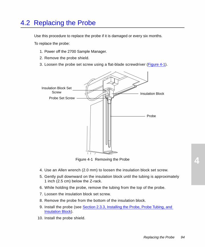
4
4.2 Replacing the Probe
Use this procedure to replace the probe if it is damaged or every six months.
To replace the probe:
1. Power off the 2700 Sample Manager.
2. Remove the probe shield.
3. Loosen the probe set screw using a flat-blade screwdriver (Figure 4-1).
Figure 4-1 Removing the Probe
4. Use an Allen wrench (2.0 mm) to loosen the insulation block set screw.
5. Gently pull downward on the insulation block until the tubing is approximately 1 inch (2.5 cm) below the Z-rack.
6. While holding the probe, remove the tubing from the top of the probe.
7. Loosen the insulation block set screw.
8. Remove the probe from the bottom of the insulation block.
9. Install the probe (see Section 2.3.3, Installing the Probe, Probe Tubing, and Insulation Block).
10. Install the probe shield.
Insulation BlockProbe Set Screw
Insulation Block Set Screw
Probe
Replacing the Probe 94
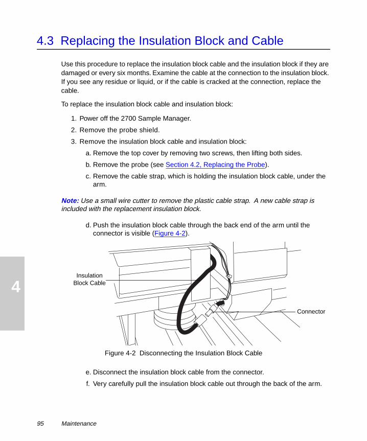
4
4.3 Replacing the Insulation Block and Cable
Use this procedure to replace the insulation block cable and the insulation block if they are damaged or every six months. Examine the cable at the connection to the insulation block. If you see any residue or liquid, or if the cable is cracked at the connection, replace the cable.
To replace the insulation block cable and insulation block:
1. Power off the 2700 Sample Manager.
2. Remove the probe shield.
3. Remove the insulation block cable and insulation block:
a. Remove the top cover by removing two screws, then lifting both sides.
b. Remove the probe (see Section 4.2, Replacing the Probe).
c. Remove the cable strap, which is holding the insulation block cable, under the arm.
Note: Use a small wire cutter to remove the plastic cable strap. A new cable strap is included with the replacement insulation block.
d. Push the insulation block cable through the back end of the arm until the connector is visible (Figure 4-2).
Figure 4-2 Disconnecting the Insulation Block Cable
e. Disconnect the insulation block cable from the connector.
f. Very carefully pull the insulation block cable out through the back of the arm.
Insulation Block Cable
Connector
95 Maintenance

4
4. Install the insulation block cable and insulation block:
a. Feed the connector of the insulation block cable through the back of the arm.
b. Attach the connector to the matching connector on the cable. Ensure that the connectors are firmly seated.
c. Adjust the cable until all slack is removed from behind the arm.
Attention: Ensure that the insulation block cable is not twisted or kinked.
d. Fasten the cable to the arm using the new plastic cable binder.
5. Install the probe (see Section 4.2, Replacing the Probe).
6. Install the probe shield.
7. Replace the top cover with two screws.
4.4 Maintaining a Syringe
To maintain the syringe, you can:
• Replace a syringe
• Inspect a syringe seal
• Replace a syringe seal
4.4.1 Replacing a Syringe
Use this procedure to replace a syringe if you want to use a different size syringe or if the syringe is leaking, worn, damaged, or every six months.
To replace a syringe:
1. Click Init HW in the Main window, then click Change Syringe in the Initialize Hardware dialog box to lower the plunger shaft to the correct position.
2. Remove the plunger screw at the base of the syringe plunger (Figure 4-3).
STOP
Maintaining a Syringe 96

4
Figure 4-3 Replacing the Syringe
3. Carefully unscrew the syringe from the bayonet fitting (about 1-1/2 turns) while pulling downward slightly.
4. Slide the syringe plunger from the lead screw.
5. Install the syringe (see Section 2.7, Installing the Syringe).
4.4.2 Inspecting the Syringe Seal
The syringe seal requires periodic replacement. The frequency depends on the duty cycle of the pump, the type of fluids being run through the system, the size of the syringe, and how well the instrument is maintained. Replace the seal if it is leaking or damaged.
To inspect the syringe seal:
1. Remove the syringe (see Section 4.4.1, Replacing a Syringe).
2. Remove the plunger from the syringe barrel.
3. Inspect the syringe seal at the tip of the plunger for wear and tear.
4. Replace the seal if it is damaged (see Section 4.4.3, Replacing the Syringe Seal).
5. Install the plunger in the syringe barrel.
6. Install the syringe on the syringe pump.
TP01560
OUTLET INLET
Syringe Barrel
Syringe Plunger
Plunger Screw
97 Maintenance

4
4.4.3 Replacing the Syringe Seal
Use this procedure to replace the seal for 0.5-, 1.0-, 2.5-, or 5.0-mL syringes. The frequency of replacement depends on the duty cycle of the pump, the type of fluids being run through the system, the size of the syringe, and how well the instrument is maintained.
Attention: To prevent damage to the O-rings beneath the seal on the 0.5-mL and 1.0-mL syringes, use care when you remove the seal. Replace the O-ring if it is damaged.
To replace the syringe seal on the plunger:
1. Remove the plunger from the syringe barrel.
2. Remove the syringe seal:
• For a small syringe (2.5 mL or smaller), use a single-edged razor or precision knife to carefully cut the seal lengthwise, then remove the seal from the plunger (Figure 4-4). Care must be taken not to damage the plunger.
Figure 4-4 Replacing the Syringe Seal
• For a 5.0-mL syringe, remove the seal from the plunger tip using a pair of pliers and gripping the seal approximately one third of the way down (Figure 4-5).
Attention: 5.0-mL syringes have O-rings beneath the seal. Be careful not to damage the O-ring. If it is necessary to replace the O-ring, slip the new O-ring over the narrow lip on the plunger.
STOP
Seal
Plunger
TP01559
STOP
Maintaining a Syringe 98

4
Figure 4-5 Removing the Seal on a 5-mL Syringe
3. Wet the O-ring (if present) and plunger tip with distilled and deionized water.
4. Place the seal on a flat surface with the open end facing up. Press the plunger tip firmly into the hole until it snaps into position.
5. For a 5.0-mL syringe, lay the plunger on a flat table top and position the plunger so that the seal (from the O-ring up) hangs over the edge (Figure 4-6). Slowly roll the plunger along the table edge, pressing firmly on the portion of the seal below the O-ring. Rotate the plunger three complete turns to ensure that the sharp, raised edge of the plunger bites into the seal for a secure fit.
Figure 4-6 Installing the Seal on a 5-mL Syringe
6. Wet the seal with distilled and deionized water and install the plunger in the syringe barrel.
7. Install the syringe on the pump.
O-Ring
Narrow Lip
Sharp Raised Edge
Syringe Plunger
O-Ring
Sharp Raised Edge
Edge of Table
99 Maintenance
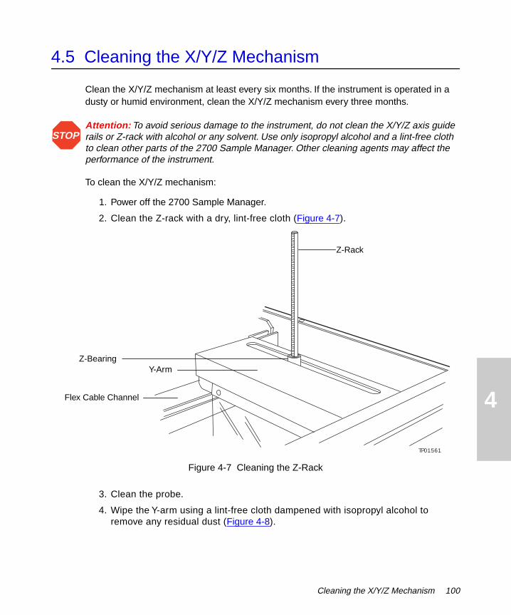
4
4.5 Cleaning the X/Y/Z Mechanism
Clean the X/Y/Z mechanism at least every six months. If the instrument is operated in a dusty or humid environment, clean the X/Y/Z mechanism every three months.
Attention: To avoid serious damage to the instrument, do not clean the X/Y/Z axis guide rails or Z-rack with alcohol or any solvent. Use only isopropyl alcohol and a lint-free cloth to clean other parts of the 2700 Sample Manager. Other cleaning agents may affect the performance of the instrument.
To clean the X/Y/Z mechanism:
1. Power off the 2700 Sample Manager.
2. Clean the Z-rack with a dry, lint-free cloth (Figure 4-7).
Figure 4-7 Cleaning the Z-Rack
3. Clean the probe.
4. Wipe the Y-arm using a lint-free cloth dampened with isopropyl alcohol to remove any residual dust (Figure 4-8).
STOP
TP01561
Z-Rack
Y-Arm
Flex Cable Channel
Z-Bearing
Cleaning the X/Y/Z Mechanism 100

4
Figure 4-8 Cleaning the Y- and Z-Axes
5. Wipe the inside of the flex cable channel using a lint-free cloth dampened with isopropyl alcohol.
Attention: Do not wipe the x-axis guide rails. The guide rails are lubricated with a grease that does not require removal unless found to be extremely dirty.
6. Wipe the inside of the X-frame with a lint-free cloth dampened with isopropyl alcohol, ensuring that the lubricant on the x-axis guide rails is not removed.
Attention: When cleaning the square shaft pinion, ensure that no alcohol enters the Z-bearing or is wiped on the y-axis guide rails.
7. Wipe the square shaft pinion located underneath the arm using a lint-free cloth dampened with isopropyl alcohol.
TP01566
Y-Arm
Flex Cable
STOP
STOP
101 Maintenance
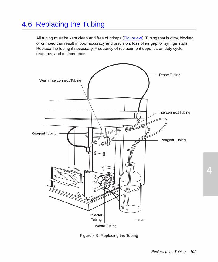
4
4.6 Replacing the Tubing
All tubing must be kept clean and free of crimps (Figure 4-9). Tubing that is dirty, blocked, or crimped can result in poor accuracy and precision, loss of air gap, or syringe stalls. Replace the tubing if necessary. Frequency of replacement depends on duty cycle, reagents, and maintenance.
Figure 4-9 Replacing the Tubing
TP01558
Reagent Tubing
Interconnect Tubing
Waste Tubing
Reagent Tubing
Probe Tubing
Wash Interconnect Tubing
InjectorTubing
Replacing the Tubing 102

4
To replace the tubing:
1. To remove the tubing, use a 5/16-in. wrench and gently loosen the fittings. Unthread the fittings using your fingers and remove the tubing.
2. To install new tubing, insert the fitting into the valve and tighten it finger tight. Using a 5/16-in. wrench, turn the fitting another 1/4- to 1/2-turn.
4.7 Replacing the 4-Port Syringe Valve
Use this procedure to replace the 4-port syringe valve if the valve is damaged or blocked.
To replace the 4-port syringe valve:
1. Power off the instrument.
2. Remove all tubing and the syringe from the 4-port syringe valve.
3. Remove the valve by loosening the two screws on the valve (Figure 4-10).
Figure 4-10 Removing the 4-Port Syringe Valve
TP01560
OUTLET INLET
Valve Screws
103 Maintenance

4
4. Install the valve:
a. Rotate the valve body so that the bayonet fitting is oriented toward the bottom of the pump.
b. Install the new valve by aligning the D coupler on the valve stem with the D hole in the encoder.
c. Gently push the valve in place, ensuring that the locating pins on the frame side of the valve body fit in the holes on the pump frame.
d. Replace the screws.
5. Connect the tubing to the 4-port syringe valve (Figure 4-11).
Figure 4-11 Installing the Syringe Pump Tubing
6. Install the syringe on the 4-port syringe valve.
7. Power on the instrument.
8. Click Init HW in the Main window, then click Initialize Robot & Pump in the Initialize Hardware dialog box.
9. Prime the pump as described in Section 2.8.2, Priming the Pumps, until all tubing is free of air bubbles.
Wash Interconnect Tubing
Manifold Block
Solvent Container
Syringe Pump
Wash Pump
Interconnect Tubing
Reagent Tubing
Replacing the 4-Port Syringe Valve 104

4
4.8 Cleaning and Lubricating the Lead Screw
Use this procedure to remove dust from the lead screw. Clean the lead screw periodically with air if the syringe pump is used in a dusty environment. Lubrication is usually only needed every 1 million syringe strokes. If the pump appears to need lubrication more frequently, suspect another problem.
Note: Use the Lubrication kit listed in Appendix B, Spare Parts and Options, to lubricate the lead screw.
Lubricate the lead screw if the pump is making an unusual noise or if the syringe is stalling frequently.
To lubricate the lead screw:
1. Click Init HW in the Main window, then click Prime Pump in the Initialize Hardware dialog box to ensure that the syringe plunger is completely closed (Figure 4-12).
Figure 4-12 Lubricating the Lead Screw
TP01563
OUTLET INLET
Lead Screw
105 Maintenance

4
2. Insert the lubrication needle through the opening in the front panel, and apply a thin vertical line of lubricant to the entire lead screw.
3. To ensure that the lubricant is spread evenly across the lead screw:
a. Click Init HW in the Main window.
b. Click Initialize Robot & Pump in the Initialize Hardware dialog box.
c. Repeat step b four times.
Do not allow any syringe to run dry more than a few cycles without solvent.
4. Click OK to close the Initialize Hardware dialog box.
4.9 Replacing the Fuses
The 2700 Sample Manager uses two 3.15-A main fuses (see Appendix A, Specifications). The power supply automatically switches configuration for your power source (110/220 Vac operation). To prevent additional instrument down time, replace both main fuses whenever one fuse fails.
Caution: To continue protection against fire hazard, replace fuses with the appropriate type and rating.
To replace a fuse:
1. Power off the 2700 Sample Manager.
2. Remove the fuse holder from the left side panel (Figure 4-13).
Figure 4-13 Replacing a Fuse
3. Remove the fuses from the fuse holder (3.15 A each).
4. Install two new fuses with the appropriate type and rating (see Table A-3 in Appendix A, Specifications).
1
0
Fuse Holder for Main Fuses
On/Off Switch
Power Cord Connector
RS-232 Connector
Replacing the Fuses 106

4
5. Install the fuse holder.
6. Power on the instrument.
7. If the fuse fails again in a short period of time, suspect another problem.(See “Contacting Waters Technical Service” earlier in this chapter.)
107 Maintenance

5
5Diagnostics and Troubleshooting
This chapter describes how to troubleshoot the Waters 2700 Sample Manager with the help of operator-initiated diagnostics and recommended troubleshooting procedures.
The 2700 Sample Manager should be checked periodically to ascertain that the instrument is operating within acceptable parameters. When running assays, it is recommended that control samples be run on a daily basis.
To keep your 2700 Sample Manager running optimally, follow the operating procedures and guidelines described in Chapter 3, Operation. Also perform the maintenance procedures described in Chapter 4, Maintenance.
To troubleshoot problems with the instrument:
• For information about error messages that have error codes, refer to Table 5-1.
• For information about hardware problems, refer to Table 5-2.
Refer to Appendix B, Spare Parts and Options, for spare parts that you can replace. Parts not included in this appendix are recommended for replacement by Waters service personnel.
Contacting Waters Technical Service
If you encounter any problems replacing parts in the 2700 Sample Manager, contact Waters Technical Service at 800-252-4752, U.S. and Canadian customers only. Other customers, call your local Waters subsidiary or Technical Service Representative, or call Waters corporate headquarters for assistance at 1-508-478-2000 (U.S.A.).
5.1 Safety and Handling
When you troubleshoot the 2700 Sample Manager, keep the following safety considerations in mind:
Safety and Handling 108
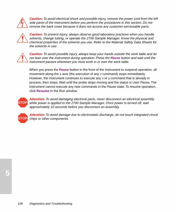
5
Caution: To avoid electrical shock and possible injury, remove the power cord from the left side panel of the instrument before you perform the procedures in this section. Do not remove the back cover because it does not access any customer-serviceable parts.
Caution: To prevent injury, always observe good laboratory practices when you handle solvents, change tubing, or operate the 2700 Sample Manager. Know the physical and chemical properties of the solvents you use. Refer to the Material Safety Data Sheets for the solvents in use.
Caution: To avoid possible injury, always keep your hands outside the work table and do not lean over the instrument during operation. Press the Pause button and wait until the instrument pauses whenever you must work in or over the work table.
When you press the Pause button in the front of the instrument to suspend operation, all movement along the z-axis (the execution of any z command) stops immediately. However, the instrument continues to execute any x or y command that is already in process, then stops. Wait until the probe stops moving and the status is User Pause. The instrument cannot execute any new commands in the Pause state. To resume operation, click Resume in the Run window.
Attention: To avoid damaging electrical parts, never disconnect an electrical assembly while power is applied to the 2700 Sample Manager. Once power is turned off, wait approximately 10 seconds before you disconnect an assembly.
Attention: To avoid damage due to electrostatic discharge, do not touch integrated circuit chips or other components.
STOP
STOP
109 Diagnostics and Troubleshooting

5
5.2 Error Messages
Use Table 5-1 to find an error code and message with the action that you can take.
Table 5-1 Error Messages
Error Code
Error Message Action
Loss of DDE Connection Reboot the computer.
1 Initialization Error Check the movement mechanism for obstructions.
Ensure that the transportation block and screw are removed.
2 Invalid Command Enter a known command that pertains to the current window.
3 Invalid Operand Check the coordinate values for the Run method.
Run another method.
Reload the software.
4 Invalid Command Sequence Click Retry or Cancel.
5 Device Not Implemented Check the power and power cord.
Check communications.
Check cables and connections.
6 Time-out Error Check communications.
Check the device.
7 Device Not Initialized Initialize the device using the Initialize Hardware dialog box.
10 Entered Move for Z-axis Out of Range Enter a Z value less than the Zmax.
Error Messages 110

5
18 Device Not Responding to Commands
Click Retry or Cancel.
Initialize the device using the Initialize Hardware dialog box.
Check cables and connections.
Reboot the computer.
20 Step Loss Detected on X-axis Click Abort, Retry, or Continue.
Check the movement mechanism for obstructions, especially on the x-axis.
Initialize the device using the Initialize Hardware dialog box.
21 Step Loss Detected on Y-axis Click Abort, Retry, or Continue.
Check the movement mechanism for obstructions, especially on the y-axis.
Initialize the device using the Initialize Hardware dialog box.
22 Step Loss Detected on Z-axis Click Abort, Retry, or Continue.
Check the movement mechanism for obstructions, especially on the z-axis.
Initialize the device using the Initialize Hardware dialog box.
Table 5-1 Error Messages (Continued)
Error Code
Error Message Action
111 Diagnostics and Troubleshooting

5
5.3 Fluidics
This section contains information on the fluidic components. Refer to Appendix D, Solvent Considerations, for specific information on solvents.
Liquid Handling Concepts
When implementing programs or methods, operators should be familiar with general rules of liquid handling.
• Treat all samples, standards, references and controls alike.
• Five submerge steps should be sufficient in most instances. If foaming is common on the liquid surface, increase the number of submerge steps.
• If diluent is used in a sampling step, aspirate the diluent first.
• If more than one liquid is to be aspirated in the same step, aspirate the smallest volume last.
• To avoid carryover, use a wash volume of five to ten times the sample volume, or at least 750 µL after each sample. You can omit a wash step only if a large amount of diluent is added.
Pump Parameters
Some pump parameters in the 2700 Sample Manager software can affect performance. These parameters include aspiration volume, dispense volume, aspiration speed, dispense speed, aspiration delay, dispense delays, cutoff values, air gaps, waste volume, conditioning volume, and probe position. Optimization of these parameters is determined empirically and depends on the type of pipetting and reagents.
Quality Control
Routinely run three quality-control samples. Quality-control samples should represent subnormal, normal, and above-normal levels of a compound. Ensure that quality-control sample results are within an acceptable range, and evaluate precision from day to day and run to run. Data collected when quality-control samples are out of range may not be valid. Do not report this data until you ensure that chromatographic system performance is acceptable.
If quality control results are unacceptable, contact Waters Technical Service to perform fluidic calibration.
Fluidics 112

5
5.4 Troubleshooting
This section provides information for troubleshooting the 2700 Sample Manager. If the suggested solutions do not solve the problem, refer to “Contacting Waters Technical Service” earlier in this chapter.
Table 5-2 Troubleshooting Hardware Problems
Problem Cause Solution
Poor precision and accuracy
The tubing is dirty, damaged, blocked, leaking, or crimped.
Replace the tubing.
The plunger tip scratched the inside of the syringe barrel.
Replace the entire syringe.
The syringe seal is worn or damaged.
Replace the syringe seal.
The injector port is leaking. Replace the injector port.
The fittings on the 4-port syringe valve are loose.
Tighten the fittings on the 4-port syringe valve.
The 4-port syringe valve is worn or leaking.
Replace the 4-port syringe valve.
The probe is scratched, worn, damaged, dirty, bent, or blocked, or the tip is bent.
Replace the probe.
The syringe is too large for the requested volumes.
Install a smaller syringe.
There are carryover effects due to inadequate rinse volume between samples.
Increase the rinse volume.
Maintenance procedures have not been performed.
Perform maintenance procedures.
113 Diagnostics and Troubleshooting
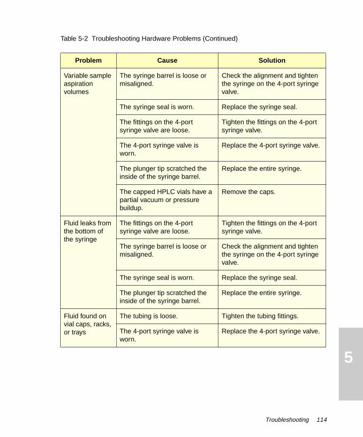
5
Variable sample aspiration volumes
The syringe barrel is loose or misaligned.
Check the alignment and tighten the syringe on the 4-port syringe valve.
The syringe seal is worn. Replace the syringe seal.
The fittings on the 4-port syringe valve are loose.
Tighten the fittings on the 4-port syringe valve.
The 4-port syringe valve is worn.
Replace the 4-port syringe valve.
The plunger tip scratched the inside of the syringe barrel.
Replace the entire syringe.
The capped HPLC vials have a partial vacuum or pressure buildup.
Remove the caps.
Fluid leaks from the bottom of the syringe
The fittings on the 4-port syringe valve are loose.
Tighten the fittings on the 4-port syringe valve.
The syringe barrel is loose or misaligned.
Check the alignment and tighten the syringe on the 4-port syringe valve.
The syringe seal is worn. Replace the syringe seal.
The plunger tip scratched the inside of the syringe barrel.
Replace the entire syringe.
Fluid found on vial caps, racks, or trays
The tubing is loose. Tighten the tubing fittings.
The 4-port syringe valve is worn.
Replace the 4-port syringe valve.
Table 5-2 Troubleshooting Hardware Problems (Continued)
Problem Cause Solution
Troubleshooting 114

5
Fluid in the drip tray, behind the drip tray, or under the instrument
The tubing has leaks, blockages, crimps, or air bubbles.
Tighten the fittings, then prime the pumps to flush air bubbles. If the tubing still has leaks, blockages, crimps, or air bubbles, replace the tubing.
The syringe barrel is loose or misaligned.
Check the alignment and tighten the syringe on the 4-port syringe valve.
The wash station is blocked. Clean the wash station and check the fittings.
The wash station tubing is damaged, blocked, loose, or leaking.
Tighten or replace the tubing.
The tubing to the waste container has a trap in the tubing.
Ensure that fluid flows freely into the waste container by vertically straightening out the tubing.
The end of the waste fluid tubing is submerged in fluid or foam in the waste container.
Ensure that the end of the tubing is not submerged in fluid or foam.
The dispensed fluid from the probe overflowed the sample container.
Decrease the volume of sample in the sample container.
The probe missed the position and dispensed onto a rack, tray, or the drip tray.
Ensure that the correct racks and trays are installed for the workspace, then calibrate the probe to all reference positions on the workspace.
Racks or trays are wet from earlier cleaning.
Dry the racks and trays thoroughly.
Noisy syringe pump
The lead screw is sticking. Clean and lubricate the lead screw.
Table 5-2 Troubleshooting Hardware Problems (Continued)
Problem Cause Solution
115 Diagnostics and Troubleshooting

5
Syringe stalls The 4-port syringe valve is defective or worn.
Replace the 4-port syringe valve.
The tubing is dirty, blocked, or crimped.
Replace the tubing.
The syringe barrel is loose or misaligned.
Check the alignment and tighten the syringe on the 4-port syringe valve.
The tubing connectors are blocked.
Clean the tubing connectors, or replace the tubing.
The lead screw is sticking. Clean and lubricate the lead screw.
Probe crash Sample containers, trays, or racks are not installed correctly.
Ensure that sample containers, trays, and racks are installed correctly.
The probe is not calibrated to the workspace.
Calibrate the probe to the workspace.
The probe is bent. Replace the probe.
The injector port is blocked or damaged.
Replace the injector port.
Broken vials Sample containers, trays, or racks are not installed correctly.
Ensure that sample containers, trays, and racks are installed correctly.
The probe is not calibrated to the workspace.
Calibrate the probe to all reference positions on the workspace.
The probe is bent. Replace the probe.
Table 5-2 Troubleshooting Hardware Problems (Continued)
Problem Cause Solution
Troubleshooting 116

5
Injector port is damaged.
The probe is damaged or bent or the tip is bent.
Replace the probe and the injector port.
The sleeve in the injector port is damaged or absent.
Inspect the probe for damage and replace the injector port.
No injection The injector port is blocked or damaged.
Replace the injector port.
The injector valve is blocked, damaged, or not operating.
Repair or replace the injector valve.*
The syringe pump is damaged or worn.
Replace the syringe pump.
The inject valve is not switching to the Inject position.
Replace the injector.
Leaking injector A fitting on the injector is loose. Tighten the fittings.
The rotor seal is damaged. Replace the rotor seal.*
Cannot initialize The fuse is blown. Replace the main fuses.
The power supply has a problem.
Contact Waters Technical Service.
Intermittent run failures
The cables are not securely plugged in.
Securely fasten all cables and the power cord.
A cable is damaged. Replace cables one at a time until the problem is solved.
Table 5-2 Troubleshooting Hardware Problems (Continued)
Problem Cause Solution
117 Diagnostics and Troubleshooting
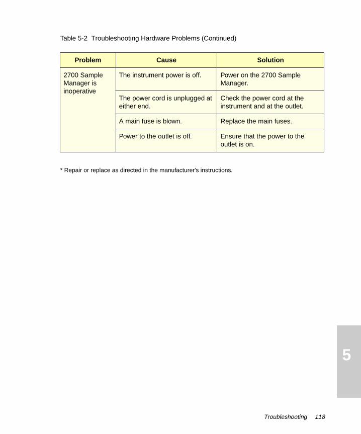
5
* Repair or replace as directed in the manufacturer’s instructions.
2700 Sample Manager is inoperative
The instrument power is off. Power on the 2700 Sample Manager.
The power cord is unplugged at either end.
Check the power cord at the instrument and at the outlet.
A main fuse is blown. Replace the main fuses.
Power to the outlet is off. Ensure that the power to the outlet is on.
Table 5-2 Troubleshooting Hardware Problems (Continued)
Problem Cause Solution
Troubleshooting 118

A
Appendix ASpecificationsThis appendix includes specifications for the following:
• Physical specifications (Table A-1)
• Environmental specifications (Table A-2)
• Electrical specifications (Table A-3)
• System operational specifications (Table A-4)
• Liquid handling specifications (Table A-5)
• Control, computer, and communication specifications (Table A-6)
Note: The performance characteristics stated in the specifications were not established by any in vitro diagnostic assays. It is the responsibility of each laboratory to verify that the system works for its applications.
Table A-1 Physical Specifications
Item Specification
Footprint (width × depth × height)
22 in. × 18 in. × 19 in. (55.9 cm × 45.7 cm × 48.3 cm)
Workspace 15.1 in. × 5.9 in. × 6.9 in. (38.4 cm × 15.0 cm × 17.5 cm)
Ventilation At least 1 in. (2.5 cm) from a wall or obstructing surface
Weight Approximately 65 pounds (30 kg)
Safety UL, C-UL, CE, IEC 1010-1
Appendix A 119

A
Table A-2 Environmental Specifications
Item Specification
Operating temperature 15 °C to 40 °C (59 °F to 104 °F)
Operating environment Indoor use
Relative humidity Maximum relative humidity 85% for temperatures up to 31 °C, decreasing linearly to 50% relative humidity at 40 °C
Storage temperature 0 °C to 50 °C (32 °F to 122 °F)
Pollution Degree 2
Altitude Up to 2,000 M (6562 feet)
Table A-3 Electrical Specifications
Item Specification
Power supply input 110/230 Vac (10% at frequencies from 47 Hz to 63 Hz). Input selection is fully automatic. Requires earth-grounded power source.
Fuses Two 3.15-A fuses at the input module.
Power supply output Generates 24 V. All devices internal to the instrument operate on 24 V.
Installation category Overvoltage Category II.
Input voltages Auto-selecting 110/230 Vac (10%).
Frequency 47 to 63 Hz.
Maximum power 150 watts.
120 Appendix A

A
* Accuracy and precision were determined within run, and coordinates were measured independently.
Table A-4 System Operational Specifications
Item X-Axis Specification Y-Axis Specification Z-Axis Specification
Travel range 383 mm (15.08 in.) 150 mm (5.91 in.) 165 mm (6.50 in.)
Travel range (steps)
1750 steps 1065 steps 1782 steps
Initialization offset
5 steps 5 steps 40 steps
Resolution per half step
0.2234 mm (0.009 in.) 0.1422 mm (0.006 in.) 0.0982 mm (0.004 in.)
Accuracy over travel*
+0.20 mm (+0.008 in.)
+0.20 mm (+0.008 in.)
+0.40 mm (+0.016 in.)
Reproducibility*
+0.10 mm (+0.004 in.)
+0.10 mm (+0.004 in.)
+0.10 mm (+0.004 in.)
Start speed 50 steps/sec
11 mm/sec
(0.43 in./sec)
200 steps/sec
28 mm/sec
(1.1 in./sec)
400 steps/sec
39 mm/sec
(1.54 in./sec)
End speed 4,000 steps/sec
894 mm/sec
(35.2 in./sec)
4,000 steps/sec
569 mm/sec
(22.4 in./sec)
4,000 steps/sec
393 mm/sec
(15.5 in./sec)
Acceleration 10,000 steps/sec2
2,235 mm/sec2
(87.9 in./sec2)
20,000 steps/sec2
2,845 mm/sec2
(112 in./sec2)
30,000 steps/sec2
2,945 mm/sec2
(116.0 in./sec2)
Appendix A 121

A
Table A-5 Liquid Handling SpecificationsItem Description
Injector volume (fixed loop) 20 µL standard; 5 µL, 10 µL, 50 µL, 100 µL, 250 µL, 500 µL, 1.0 mL, 2.0 mL, and 5.0 mL available.
Syringe sizes 100 µL, 250 µL, 500 µL, 1.0 mL, 5.0 mL.
Resolution Mechanical resolution is 1/3,000 of syringe volume. Smallest recommended volume is 24 steps or 2 µL, whichever is the larger volume.
Injection accuracy > 99% at full stroke with 500-µL syringe
Precision < 0.75% RSD; 20-µL injection volume, 20-µL fixed loop, overfill mode; six replicates; phenone mix, 254 nm; eluent and sample diluent: degassed methanol:water, 60:40, premixed; Symmetry C18 column, 3.9 × 50 mm; 1 mL/min
Carryover < 0.1%
Injector cycle time < 20 sec
Table A-6 Control, Computer, and Communication Specifications
Item Specification
Computer operating system Windows 3.1, Windows 95 , or Windows NT running on an IBM PC or compatible
Communication RS-232 serial interface
Floppy diskette drive 3.5 inch, 1.44 MB
122 Appendix A

B
Appendix BSpare Parts and Options
This appendix includes information on:
• Recommended spare parts
• Startup Kit
• Fraction collection option
Parts not included in this appendix are recommended for replacement by Waters service personnel.
B.1 Spare Parts
For recommended spare parts, see Table B-1.
Table B-1 Recommended Spare Parts
Item Part Number
Electronics
10-pin terminal strip, back panel (male plug) 272606
10-pin terminal strip, back panel (female plug) 272637
Diverter valve insulation block 272610
Insulation block with cable (380 mm long) 272051
Spare screw kit for insulation block 272057
Spare fuse kit 272044
Cables
Communications RS-232 cable with DB9 adapter to computer 272037
123 Appendix B

B
Probe arm flex cable 272035
Signal cable for inject start signal on terminal strip 020321
Tubing
Probe tubing 272083
Wash interconnect tubing from wash pump to syringe (1/4 in. x 28 in.) 272086
Internal pump tubing (two per pack) 272600
Interconnect tubing from manifold to syringe (1/4 in. x 28 in.) 272081
Reagent tubing to wash pump (1/4 in. x 28 in.) 272085
Reagent tubing to syringe pump 272082
Waste tubing (large) 272084
Wash station tubing from injector valve to wash station 272604
Syringes
Syringe, 500 µLO-ring, 500 µLSyringe seal, 500 µL
272080272079272078
Syringe, 1.0 mLO-ring, 1.0 mLSyringe seal, 1.0 mL
272617272618272619
Syringe, 2.5 mLO-ring, 2.5 mLSyringe seal, 2.5 mL
272620272621272622
Syringe, 5.0 mLO-ring, 5.0 mLSyringe seal, 5.0 mL
272623272624272625
Table B-1 Recommended Spare Parts (Continued)
Item Part Number
Appendix B 124

B
Racks
Rack, 13-mm tube (13 x 100 mm test tubes) – 100 positions 272018
Rack, Eppendorf tube – 100 positions 272019
Rack, 2MTP – 2 positions for microtiter plates 272017
Rack, 6MTP – 6 positions for microtiter plates 272016
Miscellaneous Parts
Manifold block (fits 1/4 in. x 28 in. tubing) 272056
Wash pump bulkhead fitting (inlet or outlet) (1/4 in. x 28 in.) 272602
Z-rack bar 272050
Wash station module 272055
Wash pump module 272071
Left shield 272053
Right shield 272066
Probe shield 272054
4-port syringe valve 272089
Microplate holder and screws (holds microplate on rack) 272607
Probe guide 272052
Location guides on drip tray for rack alignment 272611
Transportation block and screw 272061
Cap-piercing probe with PTFE coating 272070
Table B-1 Recommended Spare Parts (Continued)
Item Part Number
125 Appendix B
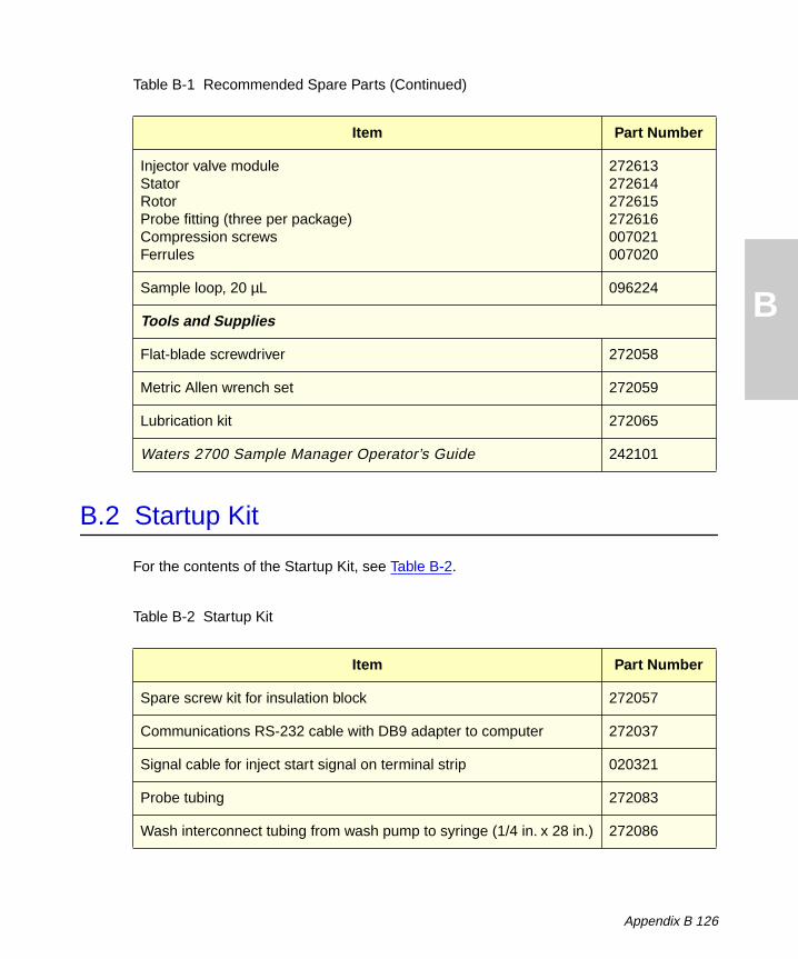
B
B.2 Startup Kit
For the contents of the Startup Kit, see Table B-2.
Injector valve moduleStatorRotorProbe fitting (three per package)Compression screwsFerrules
272613272614272615272616007021007020
Sample loop, 20 µL 096224
Tools and Supplies
Flat-blade screwdriver 272058
Metric Allen wrench set 272059
Lubrication kit 272065
Waters 2700 Sample Manager Operator’s Guide 242101
Table B-2 Startup Kit
Item Part Number
Spare screw kit for insulation block 272057
Communications RS-232 cable with DB9 adapter to computer 272037
Signal cable for inject start signal on terminal strip 020321
Probe tubing 272083
Wash interconnect tubing from wash pump to syringe (1/4 in. x 28 in.) 272086
Table B-1 Recommended Spare Parts (Continued)
Item Part Number
Appendix B 126
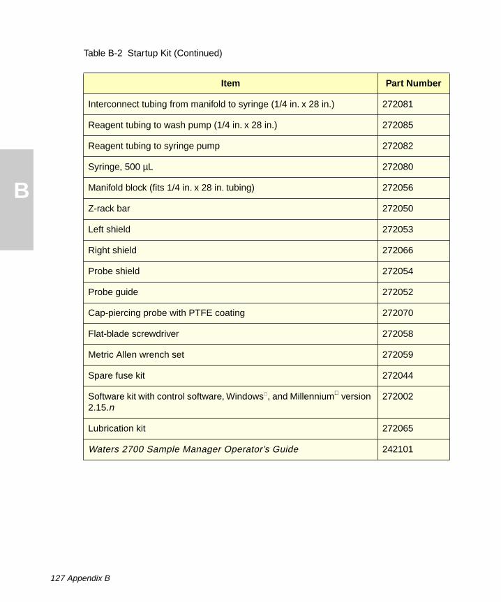
B
Interconnect tubing from manifold to syringe (1/4 in. x 28 in.) 272081
Reagent tubing to wash pump (1/4 in. x 28 in.) 272085
Reagent tubing to syringe pump 272082
Syringe, 500 µL 272080
Manifold block (fits 1/4 in. x 28 in. tubing) 272056
Z-rack bar 272050
Left shield 272053
Right shield 272066
Probe shield 272054
Probe guide 272052
Cap-piercing probe with PTFE coating 272070
Flat-blade screwdriver 272058
Metric Allen wrench set 272059
Spare fuse kit 272044
Software kit with control software, Windows , and Millennium version 2.15.n
272002
Lubrication kit 272065
Waters 2700 Sample Manager Operator’s Guide 242101
Table B-2 Startup Kit (Continued)
Item Part Number
127 Appendix B

B
B.3 Fraction Collection Option
For the contents of the optional diverter valve kit, see Table B-3.
Table B-3 Optional Diverter Valve for Fraction Collection
Item Part Number
Diverter valve module 272006
Diverter valve 272088
Diverter valve tubing kit 272626
Appendix B 128

C
Appendix CWarranty Information
This appendix includes information on:
• Limited express warranty
• Shipments, damages, claims, and returns
C.1 Limited Express Warranty
Waters Corporation provides this limited express warranty (the Warranty) to protect customers from nonconformity in the product workmanship and materials. The Warranty covers all new products manufactured by Waters.
Waters warrants that all products that it sells are of good quality and workmanship. The products are fit for their intended purpose(s) when used strictly in accordance with Waters’ instructions for use during the applicable warranty period.
Limited Warranty
WATERS Corporation warrants that the 2700 Sample Manager is for general purpose use and is not for use in clinical diagnostic procedures, and that during the Warranty period, the performance of all components of the 2700 Sample Manager [other than Third-Party Components], will not deviate materially from the Specifications for such 2700 Sample Manager. Warranties, if any, that may be applicable to Third-Party Components shall be provided by the respective manufacturers or suppliers of such Third-Party Components, and WATERS Corporation shall use reasonable efforts to assist Customer in securing the benefits of any such warranties.
129 Appendix C

C
Exclusions
The foregoing warranty does not apply to any material deviation from the Specifications by any component of the 2700 Sample Manager that results from (a) use of the 2700 Sample Manager for any purpose other than general purpose use and specifically excluding use of the 2700 Sample Manager in clinical diagnostic procedures, or use of the 2700 Sample Manager for investigational use with or without confirmation of diagnosis by another, medically established diagnostic product or procedure, (b) errors or defects in any Third-Party Component, (c) modification of the 2700 Sample Manager by anyone other than WATERS Corporation, (d) failure by Customer to install any Standard Enhancement in accordance with an update procedure, release of firmware or any operating system release, (e) any willful or negligent action or omission of Customer, (f) any misuse or incorrect use of the 2700 Sample Manager, (g) any malfunction of any information system or instrument with which the 2700 Sample Manager may be connected, or (h) failure to establish or maintain the operating environment for the 2700 Sample Manager in accordance with the Operator’s Manual.
Exclusive Remedy
In the event of any failure of the 2700 Sample Manager to perform, in any material respect, in accordance with the warranty set forth herein, the only liability of WATERS Corporation to Customer, and Customer’s sole and exclusive remedy, shall be the use, by WATERS Corporation, of commercially reasonable efforts to correct for such deviations, in WATERS Corporation’s sole discretion, replacement of the purchased 2700 Sample Manager, or refund of all amounts theretofore paid by Customer to WATERS Corporation for the 2700 Sample Manager.
Appendix C 130

C
Disclaimers
THE LIMITED WARRANTY SET FORTH HEREIN IS EXCLUSIVE AND IN LIEU OF, AND CUSTOMER HEREBY WAIVES, ALL OTHER REPRESENTATIONS, WARRANTIES AND GUARANTEES, EXPRESS OR IMPLIED, INCLUDING WITHOUT LIMITATION ANY IMPLIED WARRANTIES OF MERCHANTABILITY, FITNESS OF THE 2700 SAMPLE MANAGER FOR A PARTICULAR PURPOSE, INCLUDING FITNESS FOR USE IN CLINICAL DIAGNOSTIC PROCEDURES OR FOR INVESTIGATIONAL USE WITH OR WITHOUT CONFIRMATION OF DIAGNOSIS BY ANOTHER MEDICALLY ESTABLISHED DIAGNOSTIC PRODUCT OR PROCEDURE, OR NONINFRINGEMENT, AND ANY WARRANTIES ARISING OUT OF COURSE OF DEALING OR COURSE OF PERFORMANCE. CUSTOMER EXPRESSLY ACKNOWLEDGES THAT BECAUSE OF THE COMPLEX NATURE OF THE 2700 SAMPLE MANAGER AND ITS MANUFACTURE, WATERS CORPORATION CANNOT AND DOES NOT WARRANT THAT THE OPERATION OF THE 2700 SAMPLE MANAGER WILL BE WITHOUT INTERRUPTION OR ERROR-FREE. CUSTOMER EXPRESSLY ACKNOWLEDGES THAT CUSTOMER IS SOLELY RESPONSIBLE FOR USE OF THE 2700 SAMPLE MANAGER IN CLINICAL DIAGNOSTIC PROCEDURES OR FOR INVESTIGATIONAL USE WITH OR WITHOUT CONFIRMATION OF DIAGNOSIS BY ANOTHER MEDICALLY ESTABLISHED DIAGNOSTIC PRODUCT OR PROCEDURE.
Warranty Service
Warranty service is performed at no charge and at Waters’ option in one of three ways:
• A service representative is dispatched to the customer facility.
• The product is repaired at a Waters repair facility.
• Replacement parts with appropriate installation instructions are sent to the customer.
Nonconforming products or parts are repaired, replaced with new or like-new parts, or refunded in the amount of the purchase price, when the product is returned. Warranty service is performed only if the customer notifies Waters during the applicable warranty period.
Unless otherwise agreed at the time of sale, warranty service is not provided by dispatching a service representative when the equipment has been removed from the initial installation location to a new location outside the home country of the selling company.
Warranty service is provided during business hours (8 AM to 5 PM, Monday through Friday). Service is not available when Waters offices are closed in observance of legal holidays.
131 Appendix C

C
Warranty Service Exceptions
Warranty service is not performed on:
• Any product or part that has been repaired by others, improperly installed, altered, or damaged in any way.
• Products or parts identified prior to sale as not manufactured by Waters. In such cases, the warranty of the original manufacturer applies.
• Products that malfunction because the customer has failed to perform maintenance, calibration checks, or observe good operating procedures.
• Products that malfunction due to the use of unapproved parts and supplies.
Repair or replacement is not made:
• For expendable items such as filament devices, panel lights, fuses, batteries, and seals, if such items were operable at the time of initial use.
• Because of decomposition due to chemical action.
• For used equipment.
• Because of poor facilities, operating conditions, or utilities.
Warranty Period
The warranty period begins when the product is installed by Waters or, in the case of a customer installation, 15 days after shipment from Waters.
If an item is replaced during its warranty period, the replacement part is warranted for the balance of the original warranty period.
The warranty periods applicable to the Waters 2700 Sample Manager are shown in Table C-1.
Table C-1 2700 Warranty Periods
Assemblies and Serviceable Parts Warranty
Electronic modules 1 year
Major assemblies 1 year
Consumables No warranty
Appendix C 132

D
Appendix DSolvent Considerations
Caution: TTo avoid chemical hazards, always observe safe laboratory practices when operating your system.
D.1 Introduction
The Waters 2700 Sample Manager is compatible with all commonly used HPLC solvents.
Clean Solvents
Clean solvents provide:
• Reproducible results
• Operation with minimal instrument maintenance
A dirty solvent can cause:
• Baseline noise and drift
• Blockage of the solvent filters with particulate matter
Solvent Quality
Use HPLC-grade solvents to ensure the best possible results. Filter through 0.45-µm filters before use. Solvents distilled in glass generally maintain their purity from lot to lot; use them to ensure the best possible results.
Preparation Checklist
The following solvent preparation guidelines help to ensure stable baselines and good resolution:
• Filter solvents with a 0.45-µm filter.
• Degas and/or sparge the solvent.
• Stir the solvent.
• Keep solvents in a place free from drafts and shock.
133 Appendix D
D
Water
Use distilled and deionized water only from a high-quality water purification system. If the water system does not provide filtered water, filter it through a 0.45-µm membrane filter before use.
Buffers
When you use buffers, dissolve salts first, adjust the pH, then filter to remove insoluble material.
Tetrahydrofuran (THF)
When using unstabilized THF, ensure that your solvent is fresh. Previously opened bottles of THF contain peroxide contaminants, which cause baseline drift.
Caution: TTHF contaminants (peroxides) are potentially explosive if concentrated or taken to dryness.
D.2 Solvent Miscibility
Before you change solvents, refer to Table D-1 to determine the miscibility of the solvents to be used. When you change solvents, be aware that:
• Changes involving two miscible solvents may be made directly. Changes involving two solvents that are not totally miscible (for example, from chloroform to water) require an intermediate solvent (such as methanol).
• Temperature affects solvent miscibility. If you are running a high-temperature application, consider the effect of the higher temperature on solvent solubility.
• Buffers dissolved in water may precipitate when mixed with organic solvents.
When you switch from a strong buffer to an organic solvent, flush the buffer out of the system with distilled and deionized water before you add the organic solvent.
Appendix D 134

D
Table D-1 Solvent Miscibility
Polarity Index
SolventViscosity CP, 20 °C
Boiling Point °C (1 atm)
Miscibility Number (M)
λ Cutoff (nm)
–0.3 N-decane 0.92 174.1 29 ––
–0.4 Iso-octane 0.50 99.2 29 210
0.0 N-hexane 0.313 68.7 29 ––
0.0 Cyclohexane 0.98 80.7 28 210
1.7 Butyl ether 0.70 142.2 26 ––
1.8 Triethylamine 0.38 89.5 26 ––
2.2 Isopropyl ether 0.33 68.3 –– 220
2.3 Toluene 0.59 100.6 23 285
2.4 P-xylene 0.70 138.0 24 290
3.0 Benzene 0.65 80.1 21 280
3.3 Benzyl ether 5.33 288.3 –– ––
3.4 Methylene chloride 0.44 39.8 20 245
3.7 Ethylene chloride 0.79 83.5 20 ––
3.9 Butyl alcohol 3.00 117.7 ––- ––
3.9 Butanol 3.01 177.7 15 ––
4.2 Tetrahydrofuran 0.55 66.0 17 220
4.3 Ethyl acetate 0.47 77.1 19 260
4.3 1-propanol 2.30 97.2 15 210
4.3 2-propanol 2.35 117.7 15 ––-
135 Appendix D

D
4.4 Methyl acetate 0.45 56.3 15, 17 260
4.5 Methyl ethyl ketone 0.43 80.0 17 330
4.5 Cyclohexanone 2.24 155.7 28 210
4.5 Nitrobenzene 2.03 210.8 14, 20 ––
4.6 Benzonitrile 1.22 191.1 15, 19 ––
4.8 Dioxane 1.54 101.3 17 220
5.2 Ethanol 1.20 78.3 14 210
5.3 Pyridine 0.94 115.3 16 305
5.3 Nitroethane 0.68 114.0 –– ––
5.4 Acetone 0.32 56.3 15, 17 330
5.5 Benzyl alcohol 5.80 205.5 13 ––
5.7 Methoxyethanol 1.72 124.6 13 ––
6.2 Acetonitrile 0.37 81.6 11, 17 210
6.2 Acetic acid 1.26 117.9 14 ––
6.4 Dimethylformamide 0.90 153.0 12 ––
6.5 Dimethylsulfoxide 2.24 189.0 9 ––
6.6 Methanol 0.60 64.7 12 210
7.3 Formamide 3.76 210.5 3 ––
9.0 Water 1.00 100.0 –– ––
Table D-1 Solvent Miscibility (Continued)
Polarity Index
SolventViscosity CP, 20 °C
Boiling Point °C (1 atm)
Miscibility Number (M)
λ Cutoff (nm)
Appendix D 136
D
How to Use Miscibility Numbers (M-numbers)
Use Miscibility numbers (M-numbers) to predict the miscibility of a liquid with a standard solvent (see Table D-1).
To predict the miscibility of two liquids, subtract the smaller M-number value from the larger M-number value.
• If the difference between the two M-numbers is 15 or less, the two liquids are miscible in all proportions at 15 °C.
• A difference of 16 indicates a critical solution temperature between 25 and 75 °C, with 50 °C as the optimal temperature.
• If the difference is 17 or greater, the liquids are immiscible or their critical solution temperature is above 75 °C.
Some solvents prove immiscible with solvents at both ends of the lipophilicity scale. These solvents receive a dual M-number:
• The first number, always lower than 16, indicates the degree of miscibility with highly lipophilic solvents.
• The second number applies to the opposite end of the scale. A large difference between these two numbers indicates a limited range of miscibility.
For example, some fluorocarbons are immiscible with all the standard solvents and have M-numbers of 0, 32. Two liquids with dual M-numbers are usually miscible with each other.
A liquid is classified in the M-number system by testing for miscibility with a sequence of standard solvents. A correction term of 15 units is then either added or subtracted from the cutoff point for miscibility.
D.3 Buffered Solvents
When using a buffer, use a good quality reagent and filter it through a 0.45-µm filter.
Do not leave the buffer stored in the system after use. Flush all fluidic pathways with HPLC-quality water before shutting the system down and leave distilled and deionized water in the system (flush with 90% HPLC-quality water:10% methanol for shutdowns scheduled to be more than one day). Use a minimum of 15 mL for sparge-equipped units, and a minimum of 45 mL for in-line vacuum degasser-equipped units.
137 Appendix D

D
D.4 Head Height
Position the solvent reservoirs at a level the same as the 2700 Sample Manager. Use adequate spill protection.
D.5 Solvent Viscosity
Generally, viscosity is not important when you are operating with a single solvent or under low pressure. However when you are running a gradient, the viscosity changes that occur as the solvents are mixed in different proportions can result in pressure changes during the run. For example, a 1:1 mixture of water and methanol produces twice the pressure of either water or methanol alone.
If the extent to which the pressure changes will affect the analysis is not known, monitor the pressure during the run.
D.6 Mobile Phase Solvent Degassing
Mobile phase difficulties account for 70% or more of all liquid chromatographic problems. Using degassed solvents is important, especially at wavelengths below 220 nm. Degassing provides:
• Stable baselines and enhanced sensitivity
• Reproducible retention times for eluting peaks
• Reproducible injection volumes for quantitation
• Stable pump operation
This section presents information on the solubility of gases, solvent degassing methods, and solvent degassing considerations.
D.6.1 Gas Solubility
Only a finite amount of gas can be dissolved in a given volume of liquid. This amount depends on:
• The chemical affinity of the gas for the liquid
• The temperature of the liquid
• The pressure applied to the liquid
Appendix D 138

D
Changes in the composition, temperature, or pressure of the mobile phase can all lead to outgassing.
Effects of Intermolecular Forces
Nonpolar gases (N2, O
2, CO
2, and He) are more soluble in nonpolar solvents than in polar
solvents. Generally, a gas is most soluble in a solvent with intermolecular attractive forces similar to those in the gas (“like dissolves like”).
Effects of Temperature
Temperature affects the solubility of gases. If the heat of solution is exothermic, the solubility of the gas decreases when you heat the solvent. If the heat of solution is endothermic, the solubility increases when you heat the solvent. For example, the solubility of He in H
2O decreases with an increase in temperature, but the solubility of He
in benzene increases with an increase in temperature.
Effects of Partial Pressure
The mass of gas dissolved in a given volume of solvent is proportional to the partial pressure of the gas in the vapor phase of the solvent. If you decrease the partial pressure of the gas, the amount of that gas in solution also decreases.
D.6.2 Solvent Degassing Methods
This section describes the solvent degassing techniques that will help you to attain a stable baseline. Degassing your solvent also improves reproducibility and pump performance.
You can use either of the following methods to degas solvents:
• Sparging with helium
• Vacuum degassing
Sparging
Sparging removes gases from solution by displacing dissolved gases in the solvent with a less soluble gas, usually helium. Well-sparged solvent improves pump performance. Helium sparging brings the solvent to a state of equilibrium, which may be maintained by slow sparging or by keeping a blanket of helium over the solvent. Blanketing inhibits reabsorption of atmospheric gases.
Sparging may change the composition of mixed solvents.
139 Appendix D

D
Vacuum Degassing
The in-line vacuum degasser operates on the principle of Henry’s Law to remove dissolved gases from the solvent. Henry’s Law states that the mole fraction of a gas dissolved in liquid is proportional to the partial pressure of that gas in the vapor phase above the liquid. If the partial pressure of a gas on the surface of the liquid is reduced, for example, by evacuation, then a proportional amount of that gas comes out of solution.
Vacuum degassing may change the composition of mixed solvents.
D.6.3 Solvent Degassing Considerations
Select the most efficient degassing operation for your application. To remove dissolved gas quickly, consider the following:
Sparging
Helium sparging gives stable baselines and better sensitivity than sonication in a detector, and prevents reabsorption of atmospheric gases. Use this method to retard oxidation when you are using THF or other peroxide-forming solvents.
Vacuum Degassing
The longer the solvent is exposed to the vacuum, the more dissolved gases are removed. Two factors affect the amount of time the solvent is exposed to the vacuum:
• Flow rate – At low flow rates, most of the dissolved gas is removed as the solvent passes through the vacuum chamber. At higher flow rates, lesser amounts of gas per unit volume of solvent are removed.
• Surface area of the degassing membrane – The length of the degassing membrane is fixed in each vacuum chamber. To increase the length of membrane, you can connect two or more vacuum chambers in series.
Appendix D 140

I
DEX
NIndex
Numerics2700 project template 24, 46
2700 Sample Manager is inoperative, troubleshooting 118
2700 Sample Manager user interface 47
2MTP rack set 61
2SQUARE workspace 60
4-port syringe valve 28installing tubing 39replacing 103
6MTPrack set 60workspace, selecting 62
AAccessing Help 17, 49
Accessories 30
Accuracy 113
Activating a function 48
Adapter, serial port on computer 32
Add reagents 21setting up 83
Aligning a rack 90
As-needed maintenance 92
Aspiratingsample 22sample variation 114troubleshooting 112
Aspiration, interference with 38
Autoinjector 24
Automated column selection 57
Avoiding sample carryover 112
BBench space 33
Biological hazard 5
Broken vials, troubleshooting 116
Buttonsoperating 23pause 109sampling order 71
CCables
installing 43shielded 3
Calibrating probe 62ensuring completion 69to container 63to injector 67to wash station 68
Calibration Coordinates dialog box 66
Calibration methods 5
Cannot initialize, troubleshooting 117
Cap-piercing probe 35, 75installing 37movement of 22
Caps, sample container 75
CDC guidelines 5
Centering the probe 64, 67, 68
Changingbuffers 51column equilibration 59data 48HPLC column name 59parameters 90sample loop 52sample loop volume 53
141 Index

I
DEX
N
samples 90solvent type 76switching logic pattern 59syringe 96system parameters 21tray type 61values 48Checkingprobe calibrations 63sample order 72solvents 76
Chromatographicpeak 78system volume 58
Cleaningflex cable channel 101lead screw 105probe 29, 100racks 91shields 91square shaft pinion 101wash station and ports 91work table 91X/Y/Z mechanism 100X-frame 101Y- and Z-axes 101Z-rack 100
Clearance 33, 34
Codes, error 110
Collecting fractions 30, 78
Collection group 79, 82
Column switching valve 57entering pattern 59
Communicationprotocol 20specifications 122
Computercontrol 20rebooting 46specifications 122
Configuration, automatic for power source 106
Configure Hardware dialog box 21
Configuringfor power source 45hardware 21, 57methods 24workspace 20
Connecting2700 Sample Manager to ground 44cable to terminal strip 44digital signals 42I/O signals 42injector to HPLC System 41signals 42syringe pump tubing 104
Contacting Waters Technical Service 33, 93, 108
Containersnot provided 32reference positions 63
Control software 20, 22, 26
Control specifications 122
Controlling the run 23
Creatingcollection group 79daughter group 80daughter group, serial dilution 86new project 46parent group 81parent group, pooling fractions 82parent group, serial dilution 86reagent group 84run method 23sample group 20, 23, 70, 72sample group for fraction collection 78sample set 22target group 84workspace 23, 62
Current status 88, 89
142 Index

I
DEX
N
Custom fields 47Customizing the workspace 62
DData
acquisition 25flow 24processing 25
Database, Millennium Chromatography Manager 25
Daughter group 74, 75, 80pooling 82serial dilution 86
DDE link 20
DDE/Tool Kit application 26
Deep wash port 29, 69
Deep-well microtiter plate 20
Default workspaces 60
Degassingbenefits 138, 140considerations 140
Deleting a sample 72
Dense format microtiter plate 20
Deselecting a check box 49
Detector 23outlet 22
DeviceNot Implemented 110Not Initialized 110Not Responding to Commands 111
Digital signal connections 42
Diluent volume 87
Dispensingprobe 22sample 23, 29
Distributing tubes proportionately 80
Draining waste fluid 29, 41
I
Drip tray 20leaks 115
Drop-down menus 24
EEditing a sample group 72
Electrical control 26
Electrical specifications 120
Emptying the waste container 91
End time 79
Enlarging the Sample Group Editor window 72
Entered Move for Z-axis Out of Range 110
Enteringdata 48information in 2700 Sample Manager
Windows 48pump flow rate 80Run 21run parameters 21Run window values 77system parameters 21values 48z-coordinates 68z-coordinates for wash station
ports 69
Environmental specifications 120
Eppendorf tubes 20, 60
Equilibration, HPLC column 59
Error codes and messages 110
Error messages 110
Executing methods 24
FFailure to
initialize 117inject 117
Index 143
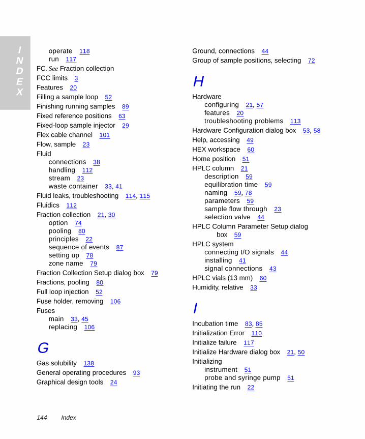
I
DEX
N
operate 118run 117FC. See Fraction collectionFCC limits 3
Features 20
Filling a sample loop 52
Finishing running samples 89
Fixed reference positions 63
Fixed-loop sample injector 29
Flex cable channel 101
Flow, sample 23
Fluidconnections 38handling 112stream 23waste container 33, 41
Fluid leaks, troubleshooting 114, 115
Fluidics 112
Fraction collection 21, 30option 74pooling 80principles 22sequence of events 87setting up 78zone name 79
Fraction Collection Setup dialog box 79
Fractions, pooling 80
Full loop injection 52
Fuse holder, removing 106
Fusesmain 33, 45replacing 106
GGas solubility 138
General operating procedures 93
Graphical design tools 24
Ground, connections 44
Group of sample positions, selecting 72
HHardware
configuring 21, 57features 20troubleshooting problems 113
Hardware Configuration dialog box 53, 58
Help, accessing 49
HEX workspace 60
Home position 51
HPLC column 21description 59equilibration time 59naming 59, 78parameters 59sample flow through 23selection valve 44
HPLC Column Parameter Setup dialog box 59
HPLC systemconnecting I/O signals 44installing 41signal connections 43
HPLC vials (13 mm) 60
Humidity, relative 33
IIncubation time 83, 85
Initialization Error 110
Initialize failure 117
Initialize Hardware dialog box 21, 50
Initializinginstrument 51probe and syringe pump 51
Initiating the run 22
144 Index

I
DEX
N
Inject start signal 44Injecting samples 22, 29, 87
Injection failure 117
Injection numbercurrent 88entering 21
Injector 52installing tubing 41leaks 117port 29port, troubleshooting 117sample flow through 23valve position 23
Inlet port 28
Input/output(I/O) connections 42signals to HPLC module 44
Inspectingcap-piercing probe 91insulation block cable 95options, accessories, and spare
parts 34shipping container 34Startup Kit 34syringe seal 97
Installation steps, primary 31
Installing2700 project template 462700 Sample Manager software 32,
325-mL syringe seal 99additional materials 32electrical connections 26fluid waste container 41fuses 106injector tubing 41instrument 32insulation block 37interconnect tubing 39main fuses 106microtiter plates 75
I
power cord 45prerequisites 31primary steps 31probe 37probe guide 36probe tubing 37racks 76racks and trays 60reagent tubing 39, 40RS-232 communications cable 43shields 54signal cable 43syringe 49syringe pump tubing 38, 104syringe valve 104tubing 38, 103wash interconnect tubing 40wash pump tubing 40waste tubing 41Z-rack 36
Insulation block 94installing 37replacing 95set screw 37
Insulation block cable 95
Insulation block set screw 94
Intended use 19
Interconnect tubing, installing 39
Interface software 26
Interference with aspiration 38
Intermittent run failures, troubleshooting 117
InvalidCommand 110Command Sequence 110Operand 110
Index 145

I
DEX
N
LLead screw 105Leaking injector, troubleshooting 117
Leaks 114
Left shield 55
Limits, electromagnetic fields 33
Liquid handling concepts 112
Liquid handling specifications 122
Loading samples 75, 76
Loss of DDE Connection 110
Lowering the probe 65
Lubricating the lead screw 105
MMagnifying glass icon 72
Main fuses 45replacing 106
Main window 48
Maintenanceconsiderations 93intervals 92
Making signal connections 42
Managingsample sequencing 22sampling 22
Manifold block 39
Materials required but not supplied 32
Menus, drop-down 24
Messages, error 110
Method set 24, 25
Microplate. See Microtiter platesMicrotiter plates 20, 60, 90
MillenniumMethod Set 21opening project 57project 46
QuickSet, current status 89required custom fields 47
Millennium Chromatography Manager 19control 24database 25installing 2700 software 32operating with 22required version 32results 25version 20
Millennium QuickSet Control window 76
Miscibility of solvents 134
Mix cycles 85serial dilution 87
Monitoring run status 23
Movingin a window 49probe 22probe arm 64
NNaming a workspace 63
New Project dialog box 46
No injection, troubleshooting 117
Noisy syringe pump, troubleshooting 115
Numberof fraction collection tubes 80of injections 77
OOpening
program in stand-alone mode 57project in Millennium 57
Operating2700 Sample Manager 56principles 22status 22system 20
146 Index

I
DEX
N
Operational status 88Options 19diverter valve 30fraction collection 22
Organic solvents 38
O-rings 98
Outlet port 28
PParameters
changing for a run 90HPLC column 59transfer from Millennium 25
Parent group 74, 75pooling fractions 81, 82serial dilution 86
Path, sample 23
Pattern, switching logic 59
Pause button 20, 23, 63, 91, 109
Pause state 109
PC-based user interface 20
Peak 21, 78, 80
Performinga run 74, 76additional runs 89fraction collection 78
Personal computer, requirements 32
Physical specifications 119
Placing the solvent container 39
Plunger, syringe 50
Pooling fractions 21pretreatment option 74, 80sequence of events 87setting up 80
Pooling Pretreatment Routine dialog box 81
Poor precision and accuracy 113
Port, injector 23
Ports, cleaning 91
I
Power cord 45
Power source, automatic configuration 45
Power supply 33, 45
Powering down 90
Precautions 5
Precipitates 38, 51
Precision 113
Preparing for a run 75
Prerequisite knowledge 15
Pretreatment 21, 74pooling fractions 74, 80Reagadd 83reagent addition 83selecting 78sequence of events after injection 87serial dilution 85
Preventing sample carryover 29, 112
Priming 51syringe pump 52wash pump 52
Principles of operation 22
Probeblockage by precipitates 38calibrating 62calibrating to injector 67calibrating to wash station 68cleaning 91current position 88initializing 51installing 37movement 22, 27, 28replacing 94tip 23x-, y-, and z-axis 28
Probe arm 27
Probe calibrationschecking 63Z-direction 65
Probe crash, troubleshooting 116
Probe guide 35
Index 147

I
DEX
N
Probe set screw 38, 94Probe shield 55
Probe tubing 35, 37, 39
Problem solving 113
Processdata 25of data flow 25of sample flow 23
Project name 22
Project template, 2700 24
Pumpprinciples of operation 51solvent 29
Pump parameters 112
Purging, syringe pump 51
QQC. See Quality Control methodsQUADMTP workspace 61
Quality control 112
Quality Control methods 3, 5
RRack 20
arrangement 24changing 90cleaning 91Set 60
Radiofrequency interference 3
Raising the probe 65
Reagadd Pretreatment Routine dialog box 84
Reagent addition 74, 83
Reagent group 75, 84
Reagent tubing 39installing 40
Reagent volume 85
Rebooting computer 46
Recommended z-coordinates for wash station 69
Reduce icon 71
Reference position 61, 63
Removing5-mL syringe seal 99dust from lead screw 105fuse holder 106syringe 96syringe valve 103top cover 34transportation block 35tubing 103
Replacing4-port syringe valve 103insulation block and cable 95main fuses 106probe 94syringe 96syringe seal 97tubing 102
Requirementsclearance 34materials 32site 32
Reservoirs, positioning 39, 138
Resuming operation 109
Retention time 79
Reviewingcurrent status 88status with Millennium 88
Right shield 54
Rinse volume 21, 77
Rinsing probe 22
Routine maintenance procedures 92
RS-232installing communications cable 43port 22
148 Index

I
DEX
N
Runinitiating 22method 21, 23window 21, 23, 77
Runningmethod 73Windows operating system 20
Runtime, entering 77
SSafety considerations 108
Samplechanging 90containers 19, 24, 60currently in process 88deleting 72flow 24injection 87interference with aspiration 38path 23tray 20volume 21volume, entering 77
Sample group 21creating 70, 72deleting 72description 70editing 72preparing 23selecting the order 72values 77
Sample Group Editortool 20window 71Zoom dialog box 73
Sample loop 22changing 52changing volume 53sample flow through 23
I
standard size 29volume 58
Sampling 22order 71routine 21
Savingrun method 23sample group 23workspace 23
Securing tubing 39
Select & Place Rack Sets dialog box 62
Selecting6MTP 62check box 49HPLC column 26item 48pretreatment options 74, 81reference position 64workspace 60
Semi-annual maintenance 92
Sendingcolumn switching valve signal 26signals 22
Sequence of events in pretreatment options 74
Sequencing samples 22
Serdilut Pretreatment Routine dialog box 86
Serial dilution 21number of 87pretreatment option 75, 85sequence of events 88setting up 85
Serial port, DB9 32
Setting up2700 project 46add reagents 83pool fractions 80serial dilution 85
Shallow wash port 29, 69
Shields, cleaning 91
Index 149
I
DEX
N
Shutting down the system 90Signalconnections to HPLC system 43inject start 44installing cable 43
Single sample, selecting 72
Site requirements 32
Size of instrument 33
Slice time, fraction collection 80
Software program, 2700 Sample Manager 24, 32
Solventbuffered solvents 137changing 76checking before a run 76container 33container placement 39general considerations 133guidelines 133installing tubing 39, 40miscibility 134viscosity considerations 138
Solvent reservoirs. See ReservoirsSolving problems 113
Sparge, overview 139
Specifications 119, 123communications 122computer 122control 122electrical 120environmental 120liquid handling 122operating system 121physical 119
Spills 114
Spills, drip tray 20
Square shaft pinion 101
SquareSet 60
Stand-alone modeopening program 57
operating 76software requirements 32
Standard-well microtiter plate 20
Startbutton 23signal 22time 79
Startinga run 22injection 88routine operation 57
Startup Kit 32, 34
Startup project 46
Static electricity 33
Statusmonitoring 23operating 22operational 88sample 23
Step Loss Detectedon X-axis 111on Y-axis 111on Z-axis 111
Stop button 23
Stopping the probe 20
Stopping the run 90
Suspending operation 109
Switching logic pattern 59
Syringebarrel 50installing 49installing tubing 40plunger 23, 50replacing 96stalls, troubleshooting 116volume 58
Syringe pump 22description 28initializing 51installing tubing 39, 40
150 Index

I
DEX
N
operation 28priming 52troubleshooting 115tubing 38Syringe sealinspecting 97replacing 98
Syringe valve, replacing 103
Syringe, fluid leaks 114
Systemchanging parameters 21entering parameters 21name 22operational specifications 121volume 57, 58
TTarget group 75, 84
reagent addition 83
Temperature, operating 33
Terminal setup 20, 22
Terminal strip, connecting 44
Test tube racks 20
Test tubes (13 mm) 60
Tightening the fittings 39
Time, Run 21
Time-out Error 110
Tools, graphical design 24
Top cover, removing 34
Transfer volumepooling fractions 82serial dilution 87
Transferring samples to column 22
Transportbracket 35screw 35
Tray selection button 61
Tray type, changing 61
I
Triggering operation 20
Troubleshooting 113hardware problems 113
TTL. See Terminal setupTubes per fraction, pooling fractions 82
Tubingconnecting to syringe pump 104injector, not provided 32installing 38installing probe tubing 37interconnect 39reagent 39replacing 102securing 39syringe pump 38, 40wash pump 40
UUnlocking the arm 34
Unpacking the instrument 34
Using2700 software 24arrow keys to center the probe 64keyboard 48keyboard to calibrate the probe 64mouse 48
VValues, entering and changing 48
Valve, HPLC column selection 44
Variable sample aspiration volumes 114
Ventilation 33
Verifying probe calibrations 69
Vials broken 116
Viewing entire rack 72
Volumes of wash fluids 28
Index 151

I
DEX
N
WWarranty information 129Wash fluid 28
Wash interconnect tubing 40
Wash pump 22installing tubing 40priming 52
Wash station 22, 29, 91
Wash time 85pooling fractions 83serial dilution 87
Washinginjector 29probe 22, 28, 29
Waste container 91
Waste fluid, drainage 41
Waste port 29
Waste station 69
Waters Technical Service 33, 93, 108
Weight of instrument 33
Wetting the syringe 49
Windows, Microsoft 24
WipingY-arm 100Z-rack 91
Work table 20, 27cleaning 91
Workspace 23customizing 62default 60maximum limit 62
Workspace Editor window 20, 24, 61
XX/Y/Z mechanism
cleaning 100
X/Y/Z robotic arm 35installing 35movement of 35unlocking 34
X/Y/Z robotic module 27
X-axis 28
X-axis guide rails 101
X-frame 101
YY-axis 28
Y-axis guide rails 101
Y-frame 36
ZZ-axis 28
Z-axis probe calibrations 65
Z-bearing 36, 101
Zdisp 65, 69
Zmax 65, 69
Zone 21, 78, 79
Zoom icon 71
Zoom mode 72
Zooming the Sample Group Editor window 72
Zpos 66, 69
Z-rack 35installing 36moving 23wiping 91
Zstart 65, 69
Ztravel 65
152 Index