Embed Size (px)
Citation preview

Product & Installation Manual : Water-Wall™ TL-1 Barrier & Mini SLED End Treatment
Ph 0800 655 200 or visit www.csppacific.co.nz May 2013 / Page 1
Water-Wall™ TL-1
Barrier and Mini
SLED End Treatment
Product & Installation Manual : Water-Wall™ TL-1 Barrier & Mini SLED End Treatment
Ph 0800 655 200 or visit www.csppacific.co.nz May 2013 / Page 2
Table of Contents Introduction ........................................................................................................... 3
Limitations and Warnings ..................................................................................... 4
Safety Statements ................................................................................................. 5
System Design & Design Considerations .............................................................. 6
Product Components ............................................................................................. 8
General Specifications .......................................................................................... 9
Clear Area .......................................................................................................... 10
Installation Preparation ........................................................................................ 11
Installation Instructions ....................................................................................... 12
Mini SLED End Treatment Installation ................................................................ 14
Connecting the Mini SLED End Treatment ......................................................... 15
Maintenance and Repair ..................................................................................... 16
Water Freezing Prevention .................................................................................. 17
Redeployment to Another Site ............................................................................ 17
Appendix – Technical Drawings and Details
Water-Wall™ TL-1 Repair Procedure ................................................................. 18
Water-Wall™ TL-1 Patch Repair ......................................................................... 19
Water-Wall™ TL-1 Safety Zone with Mini SLED End Treatment ........................ 20
Water-Wall™ TL-1 Safety Zone without End Treatment ..................................... 21
Interim Letter of Acceptance ............................................................................... 22
Product & Installation Manual : Water-Wall™ TL-1 Barrier & Mini SLED End Treatment
Ph 0800 655 200 or visit www.csppacific.co.nz May 2013 / Page 3
Introduction Water-Wall™ TL-1 is a barrier made up of plastic units that when joined together using a steel pin and filled with water provides positive work zone barrier protection to temporary construction sites and other miscellaneous roadside activities. When an impacting vehicle contacts the Water-Wall™ TL-1, the plastic container ruptures and disperses its ballast water bringing the impact vehicle to a controlled stop or redirecting the impacting vehicle. The Water-Wall™ TL-1 barrier connects directly to the Mini SLED End Treatment which negates the need to shield or flare the ends of the barrier. Water-Wall™ TL-1 barrier is designed, tested and constructed to provide acceptable structural adequacy, minimal occupant risk and safe trajectory as set forth in NCHRP 350 for longitudinal barriers. When impacted with a 820kg vehicle at an angle of 20deg and a 2,000kg vehicle at an angle of 25 deg, both at a speed of 50kph, the impacting vehicle is stopped, re-directed or contained in a safe manner. When correctly installed the system is capable of stopping, containing or re-directing an errant vehicle in a safe manner under NCHRP 350 impact conditions. The Mini SLED End Treatment is designed, tested and constructed to provide acceptable structural adequacy, minimal occupant risk and safe trajectory as set forth in MASH for crash cushions. When the Mini SLED End Treatment was impacted with an 1100kg and a 2270kg vehicle head on the vehicle was stopped or re-directed in a safe manner under MASH TL-1 impact conditions.

Product & Installation Manual : Water-Wall™ TL-1 Barrier & Mini SLED End Treatment
Ph 0800 655 200 or visit www.csppacific.co.nz May 2013 / Page 4
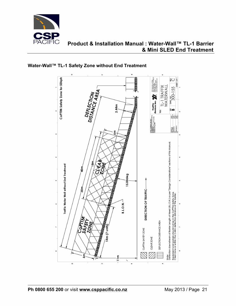
Before Installation Placement of the Water-Wall™ TL-1 shall be in accordance with the design as provided for the temporary work zone. Installation shall be in accordance with the installation instructions supplied for this product. Depending on the circumstances at the site, installation including filling of a unit (using a truck mounted water tanker) should take no more than 1 minute for each 1.854m long unit. Water-Wall™ TL-1 is a highly engineered safety device made up of a relatively small number of parts. Before starting installation ensure that one is familiar with the make up of the system. Limitations and Warnings Water-Wall™ TL-1 barrier has been rigorously tested and evaluated per the evaluation criteria in the NCHRP 350 guidelines for a longitudinal barrier. The impact conditions recommended in NCHRP 350 are intended to address typical in-service collisions. When properly installed and maintained Water-Wall™ TL-1 barrier allows an impacting vehicle to be stopped, contained or re-directed in a safe and predictable manner under the NCHRP 350 impact conditions. Vehicle impact characteristics different than, or in excess of, those encountered in NCHRP 350 testing (weight, speed and angle) may result in system performance that does not meet the NCHRP 350 evaluation criteria. The adjacent road operating speed must be limited to 50kph and the installation should endeavour to minimise the impact angles to 25 degrees (1 lateral : 2.14 forward). Water-Wall™ TL-1 barrier has a permanent deflection of 2.4m and workers, equipment and materials should be a minimum of 2.4m behind the barrier. The Water-Wall™ TL-1 barrier is installed with the Mini SLED end treatment. By exception if the Mini SLED end treatment is not used the end of the barrier must be shielded or flared as per the layout drawings in the appendix of this manual. These technical drawings show the Safety Zones with and without the Mini SLED end treatment. If further assistance is required please contact CSP Pacific.
Product & Installation Manual : Water-Wall™ TL-1 Barrier & Mini SLED End Treatment
Ph 0800 655 200 or visit www.csppacific.co.nz May 2013 / Page 5
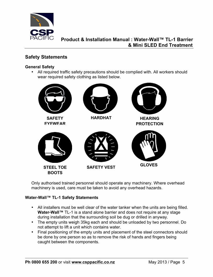
Safety Statements General Safety
• All required traffic safety precautions should be complied with. All workers should wear required safety clothing as listed below.
Only authorised trained personnel should operate any machinery. Where overhead machinery is used, care must be taken to avoid any overhead hazards.
Water-Wall™ TL-1 Safety Statements
• All installers must be well clear of the water tanker when the units are being filled. Water-Wall™ TL-1 is a stand alone barrier and does not require at any stage during installation that the surrounding soil be dug or drilled in anyway.
• The empty units weigh 35kg each and should be unloaded by two personnel. Do not attempt to lift a unit which contains water.
• Final positioning of the empty units and placement of the steel connectors should be done by one person so as to remove the risk of hands and fingers being caught between the components.
STEEL TOE BOOTS
SAFETY VEST GLOVES
SAFETY EYEWEAR
HARDHAT HEARING PROTECTION
Product & Installation Manual : Water-Wall™ TL-1 Barrier & Mini SLED End Treatment
Ph 0800 655 200 or visit www.csppacific.co.nz May 2013 / Page 6
System Design and Design Considerations Slopes A maximum approach and cross slope of 1:10 is preferable. On slopes greater than this approval is required from the road controlling authority. Undulating Ground Conditions Site specific grading may be necessary to ensure that there are no “humps” or “hollows” that may significantly alter the impacting vehicles stability or substantially alter the barrier height in relation to the ground. Foundation Requirements The Water-Wall™ TL-1 is a free standing longitudinal barrier requiring only that the road surface support the fully filled linked sections. It is recommended Water-Wall™ TL-1 be installed on a compacted surface. Appropriate surfaces for installation include concrete, asphalt, dirt and gravel surfaces. Curbs As with all road side safety hardware, Water-Wall™ TL-1 barrier has been designed and tested so the centre of gravity of the impacting vehicle is a constant height in relation to the system. For this reason, it is preferred that curb or channels not be in front of the barrier as it will alter the height of the vehicle at impact. Curb behind the barrier will affect the performance of the system through limiting deflection. If there is no option but to install in front, behind or on a curb, approval is required from the road controlling authority.
Product & Installation Manual : Water-Wall™ TL-1 Barrier & Mini SLED End Treatment
Ph 0800 655 200 or visit www.csppacific.co.nz May 2013 / Page 7
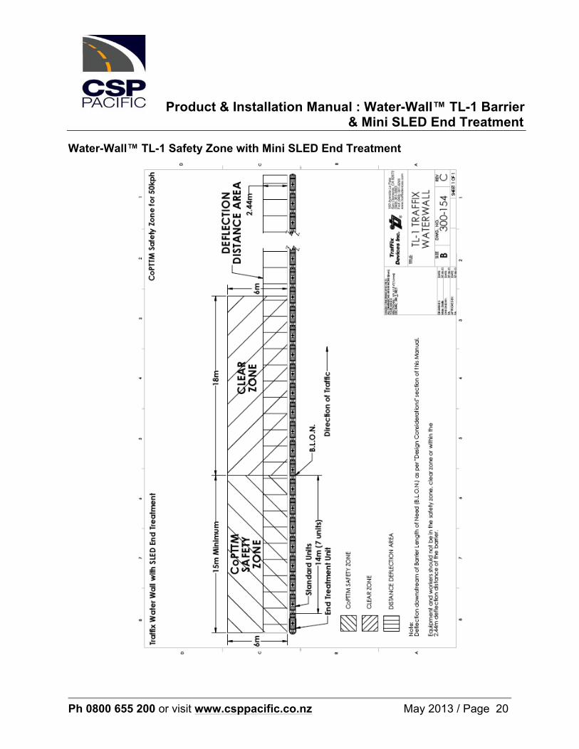
Median and Roadside Applications Water-Wall™ TL-1 barrier can be used in both ‘roadside’ and ‘median’ applications. End Treatment The Mini SLED end treatment is a free standing end unit that is fitted to the Water-Wall™ TL-1 barrier in a tangent position. If the Mini SLED end treatment is not used it will be required to flare the barrier as shown in the technical drawings in the appendix of this manual. Length Of Need The Length of Need (LoN) of the Mini SLED End Treatment when connected to the barrier is the end treatment plus seven Water-Wall™ TL-1 units. To accommodate the LoN the total system requirement is 26 units plus two end treatment units if both ends are protected. Ensure when installing the barrier that it is sufficient length and the placement of the end treatment is as required by this manual.
Product & Installation Manual : Water-Wall™ TL-1 Barrier & Mini SLED End Treatment
Ph 0800 655 200 or visit www.csppacific.co.nz May 2013 / Page 8
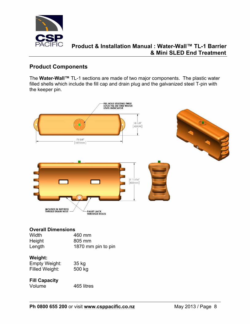
Product Components The Water-Wall™ TL-1 sections are made of two major components. The plastic water filled shells which include the fill cap and drain plug and the galvanized steel T-pin with the keeper pin.
Overall Dimensions Width 460 mm Height 805 mm Length 1870 mm pin to pin Weight: Empty Weight: 35 kg Filled Weight: 500 kg Fill Capacity Volume 465 litres
Product & Installation Manual : Water-Wall™ TL-1 Barrier & Mini SLED End Treatment
Ph 0800 655 200 or visit www.csppacific.co.nz May 2013 / Page 9
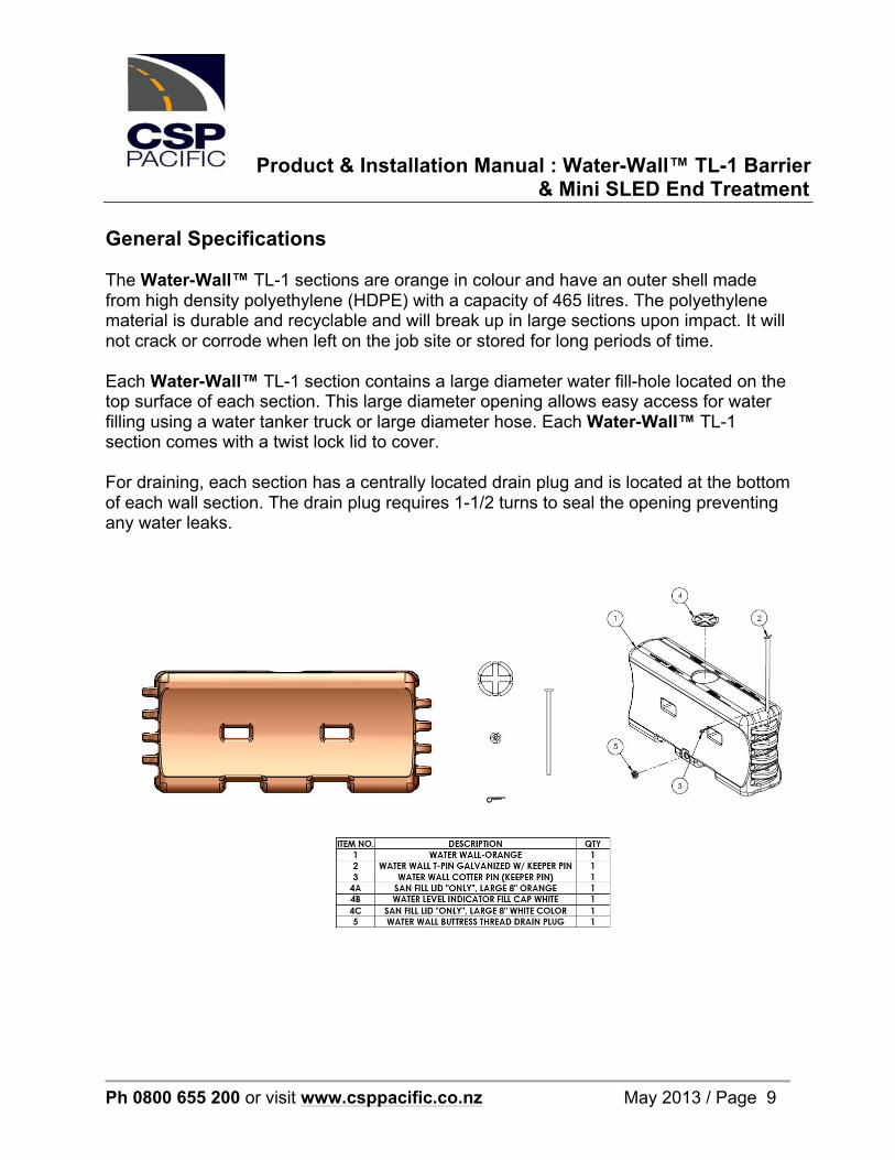
General Specifications The Water-Wall™ TL-1 sections are orange in colour and have an outer shell made from high density polyethylene (HDPE) with a capacity of 465 litres. The polyethylene material is durable and recyclable and will break up in large sections upon impact. It will not crack or corrode when left on the job site or stored for long periods of time. Each Water-Wall™ TL-1 section contains a large diameter water fill-hole located on the top surface of each section. This large diameter opening allows easy access for water filling using a water tanker truck or large diameter hose. Each Water-Wall™ TL-1 section comes with a twist lock lid to cover. For draining, each section has a centrally located drain plug and is located at the bottom of each wall section. The drain plug requires 1-1/2 turns to seal the opening preventing any water leaks.

Product & Installation Manual : Water-Wall™ TL-1 Barrier & Mini SLED End Treatment
Ph 0800 655 200 or visit www.csppacific.co.nz May 2013 / Page 10
Clear Area When installing the Water-Wall™ TL-1, a clear area must be kept clear on the work zone side to allow for backside deflection into the work zone. When impacted at the design speed of 50 km/hr at an impact angle of 25° with a 2000 kg, impact vehicle the deflection is 2.44m. This is the minimum clear area required on the work zone side. Water-Wall™ TL-1 Crash Test Data Summary
Test Level NCHRP350 1-11 50km/h Date of Test 2/6/2004 Vehicle Mass 2096 kg Impact Speed 51.4km/h Impact Angle 25 deg
Accident Severity Index 0.26 ASI Deflection 2.44m

Product & Installation Manual : Water-Wall™ TL-1 Barrier & Mini SLED End Treatment
Ph 0800 655 200 or visit www.csppacific.co.nz May 2013 / Page 11
Installation Preparation Getting Started It is essential that Water-Wall™ TL-1 barrier and the Mini SLED end treatment, are installed correctly. Please read carefully and understand the following instructions before installing Water-Wall™ TL-1 and the Mini SLED. Note: These instructions relate only to the installation of Water-Wall™ TL-1 barrier and Mini SLED end treatment and are for standard installations only. Water-Wall™ TL-1 has exactly the same components and barrier setup whether in a ‘roadside’ or ‘median’ application. For installations, commence placement of the units at one end and connect the units together until the correct barrier length and position is achieved. Preparation Before installing Water-Wall™ TL-1 ensure that all components required for the system are on site and have been identified. Before starting installation ensure that one is familiar with the make up of the system. Refer to the Product Components section in the manual for more information. Ensure that the approach and clear areas, where Water-Wall™ TL-1 is to be installed, are flat enough (i.e. a maximum slope of 1:10) and compacted so that the ground conditions will not significantly alter the height of the vehicle in relation to the height of the barrier. Minor site grading maybe required. Tools Required There are no tools required to install the Water-Wall™ TL-1 components. The units can be manually lifted and positioned by two personnel and the T-pin used to connect the units is simply dropped into position and secured with the keeper pin. Each barrier unit requires approx. 465 litres of water and it is recommended that a large truck mounted tanker is sourced for fast barrier construction.
The Mini SLED End Treatment is not filled with water.
Product & Installation Manual : Water-Wall™ TL-1 Barrier & Mini SLED End Treatment
Ph 0800 655 200 or visit www.csppacific.co.nz May 2013 / Page 12
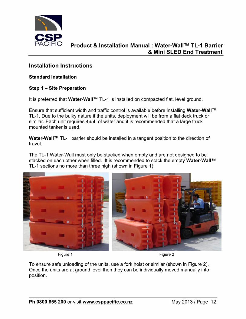
Installation Instructions Standard Installation Step 1 – Site Preparation It is preferred that Water-Wall™ TL-1 is installed on compacted flat, level ground. Ensure that sufficient width and traffic control is available before installing Water-Wall™ TL-1. Due to the bulky nature if the units, deployment will be from a flat deck truck or similar. Each unit requires 465L of water and it is recommended that a large truck mounted tanker is used. Water-Wall™ TL-1 barrier should be installed in a tangent position to the direction of travel. The TL-1 Water-Wall must only be stacked when empty and are not designed to be stacked on each other when filled. It is recommended to stack the empty Water-Wall™ TL-1 sections no more than three high (shown in Figure 1).
Figure 1 Figure 2
To ensure safe unloading of the units, use a fork hoist or similar (shown in Figure 2). Once the units are at ground level then they can be individually moved manually into position.

Product & Installation Manual : Water-Wall™ TL-1 Barrier & Mini SLED End Treatment
Ph 0800 655 200 or visit www.csppacific.co.nz May 2013 / Page 13
Step 2 – Placement of the Barrier Units Unload the units and set out in a row along the intended barrier position. Make sure the configuration of the ends will fit together where they join. Note: Lifting the units is a two person job; they weigh 35kg each when empty. Slide the units into position. The units must flush fit together so the vertical concentric holes on each unit line up. Note: None of the units are fixed to the ground in any way. Step 3 – Connecting the Barrier Units One the units are ‘flush fit’ aligned, the vertical connecting pin can be positioned down through the concentric aligned holes. Note: If a curvature of the barrier is required, position at this point. Insert the safety keeper pin into the alignment hole at the bottom of each T-pin. The T-pin and keeper pin must be inserted to finalise the installation on each wall section. The lower end of the T-pin should come in contact with the grade surface to ensure that the pin is fully inserted. Step 4 – Filling the Barrier Units When the Water-Wall™ TL-1 has been placed in accordance with the site plan and the sections linked together, the twist lock fill cap for each section should be removed. Using a truck mounted tanker fill each unit to the top with water. The fill cap is then re-installed while insuring that all tabs are engaged. Check that there are no leaks before filling the next unit. If there is a leak the unit must be replaced. It may be possible to fix at a later stage depending on the damage. Refer the Maintenance and Repair section.
Product & Installation Manual : Water-Wall™ TL-1 Barrier & Mini SLED End Treatment
Ph 0800 655 200 or visit www.csppacific.co.nz May 2013 / Page 14
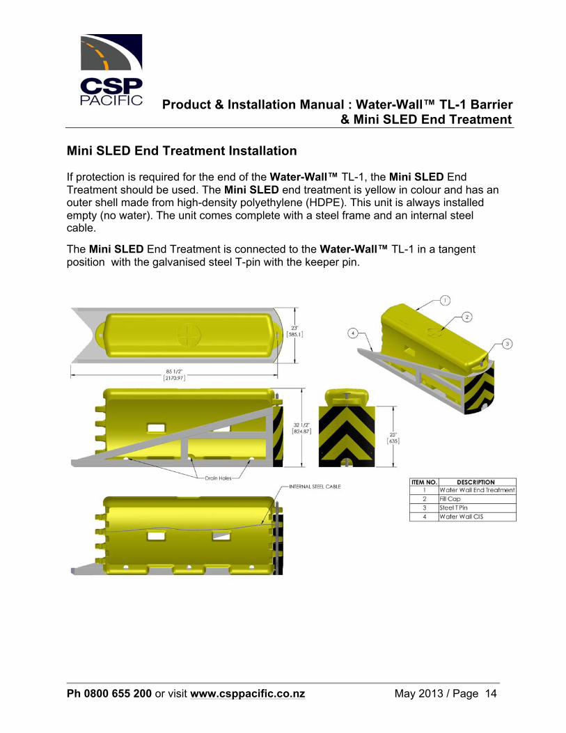
Mini SLED End Treatment Installation If protection is required for the end of the Water-Wall™ TL-1, the Mini SLED End Treatment should be used. The Mini SLED end treatment is yellow in colour and has an outer shell made from high-density polyethylene (HDPE). This unit is always installed empty (no water). The unit comes complete with a steel frame and an internal steel cable.
The Mini SLED End Treatment is connected to the Water-Wall™ TL-1 in a tangent position with the galvanised steel T-pin with the keeper pin.

Product & Installation Manual : Water-Wall™ TL-1 Barrier & Mini SLED End Treatment
Ph 0800 655 200 or visit www.csppacific.co.nz May 2013 / Page 15
Connecting the Mini SLED End Treatment Move the Mini SLED End Treatment into position at the end of the Water-Wall™ TL-1 installation, aligning the attachment hole so the vertical connecting pin can be positioned down through the concentric aligned holes. Insert the T-pin and keeper pin, linking the yellow Mini SLED end treatment unit and orange Water-Wall™ TL-1 unit. Insert the safety keeper pin into the alignment hole at the bottom of the T-pin. The T-pin and keeper pin must be inserted to finalise the installation. The lower end of the T-pin should come in contact with the grade surface to ensure that the pin is fully inserted.
Note: The Yellow Mini SLED module is NOT filled with water. The Mini SLED End Treatment must not be attached or anchored to the ground, or any other object. The maximum cross slope or approach slope the End Treatment may be used on is 1 in 10. On slopes greater than this approval is required from the road controlling authority. Delineation may be required by the Road Controlling Authority guidelines. For further details consult MoTSaM, Part 2 or contact CSP Pacific.
Product & Installation Manual : Water-Wall™ TL-1 Barrier & Mini SLED End Treatment
Ph 0800 655 200 or visit www.csppacific.co.nz May 2013 / Page 16
Maintenance and Repair
Water-Wall™ TL-1 is a maintenance free system, although it is recommended that inspections are carried out periodically. The water level should be checked periodically to insure that each section is properly filled. The Water-Wall™ TL-1 is not fully effective unless each section is filled. Severely damaged sections should be removed and replaced. Small leaking sections can be repaired as described below. When patching leaks (holes or cracks) the Water-Wall™ TL-1 plastic must be dry, free of dirt, and grease. In addition, any paint or added finish beyond the factory plastic surface should be removed. Plastic welding is the most common method for repairing damaged sections. A small butane torch is used for applying heat to the plastic rod. The rod should be melted to the patch and the wall surface in order to create a bonding patch. Temperature for bonding the plastic is 260-290°C. The torch head should be held 65 to 130 mm away from the weld surface. Care should be taken when applying heat to plastic to insure that the melting occurs only as desired. The appropriate respiratory and safety equipment should be worn and the work done in a well ventilated area. NOTE: Repairing a crack or hole does not return the plastic to its original strength, although most repairs are sufficient to insure a water tight section. Monitoring of the repair should be done for a short period after filling to insure that the repair has been done properly. If leaks cannot be completely sealed, the section should be replaced. The T-pins may be difficult to remove after an impact. A fork lift will facilitate wall realignment if necessary, without removing the T-pins or to relieve the force on the T-pins for removal.
Product & Installation Manual : Water-Wall™ TL-1 Barrier & Mini SLED End Treatment
Ph 0800 655 200 or visit www.csppacific.co.nz May 2013 / Page 17
Water Freezing Prevention In freezing weather conditions, allowing the water in the Water-Wall™ TL-1 to freeze to a solid mass of ice will affect the performance of the barrier. If the temperature at the installation site is expected to be at or below the freezing point of water, it is recommended that an additive be used to prevent the water in the units from freezing. The following additives can be used to stop the water freezing. For percentages required, cost and environmental impact and reduced temperature, consultant with a third party is required. Sodium Chloride, Calcium Chloride, Ethylene/Propylene Glycol, Liquid CMA and Potassium Acetate can all be used. Check with the road controlling authority on the additive suitability. Redeployment to Another Site
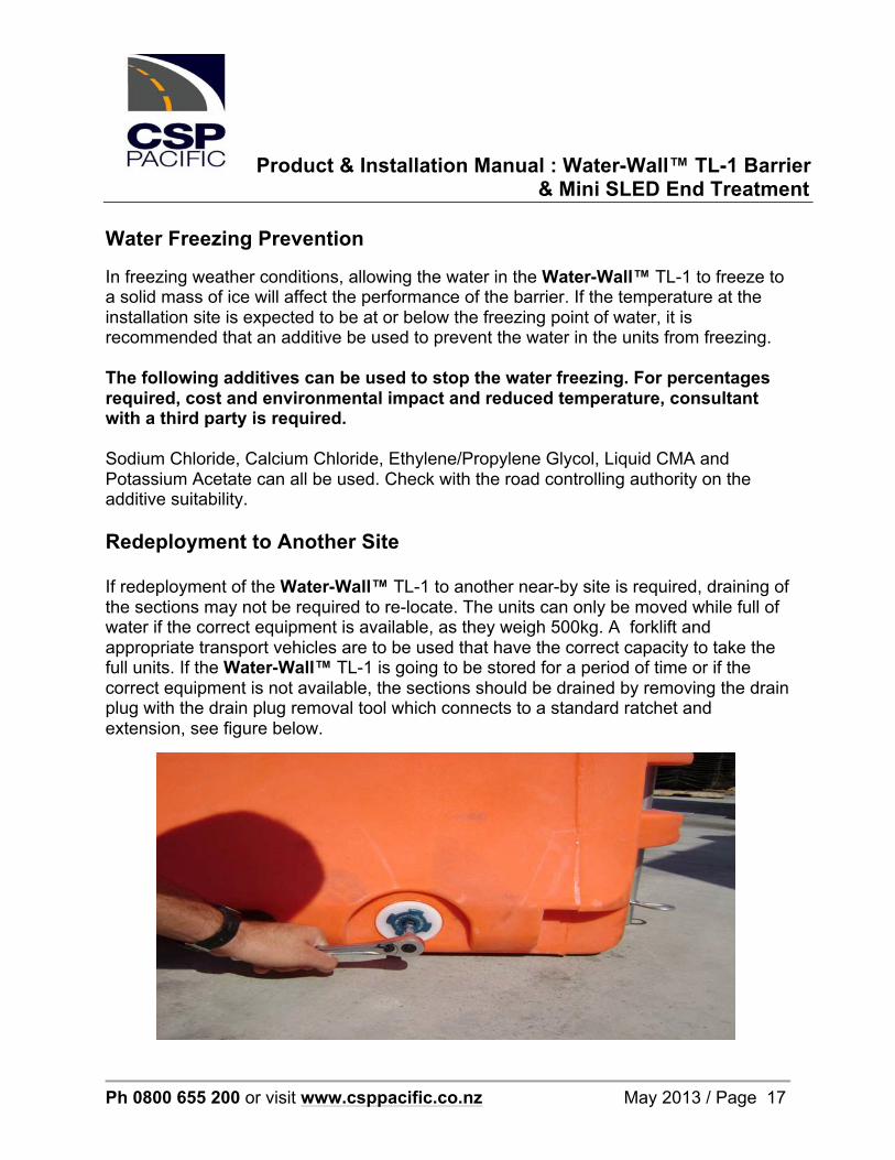
If redeployment of the Water-Wall™ TL-1 to another near-by site is required, draining of the sections may not be required to re-locate. The units can only be moved while full of water if the correct equipment is available, as they weigh 500kg. A forklift and appropriate transport vehicles are to be used that have the correct capacity to take the full units. If the Water-Wall™ TL-1 is going to be stored for a period of time or if the correct equipment is not available, the sections should be drained by removing the drain plug with the drain plug removal tool which connects to a standard ratchet and extension, see figure below.

Product & Installation Manual : Water-Wall™ TL-1 Barrier & Mini SLED End Treatment
Ph 0800 655 200 or visit www.csppacific.co.nz May 2013 / Page 18
Appendix – Technical Drawings Water-Wall™ TL-1 Repair Procedure

Product & Installation Manual : Water-Wall™ TL-1 Barrier & Mini SLED End Treatment
Ph 0800 655 200 or visit www.csppacific.co.nz May 2013 / Page 19
Water-Wall™ TL-1 Patch Repair
Product & Installation Manual : Water-Wall™ TL-1 Barrier & Mini SLED End Treatment
Ph 0800 655 200 or visit www.csppacific.co.nz May 2013 / Page 20
Water-Wall™ TL-1 Safety Zone with Mini SLED End Treatment
Product & Installation Manual : Water-Wall™ TL-1 Barrier & Mini SLED End Treatment
Ph 0800 655 200 or visit www.csppacific.co.nz May 2013 / Page 21
Water-Wall™ TL-1 Safety Zone without End Treatment

Interim Acceptance for Water-WallTM + Mini-SLEDTM Plastic Barrier System May 2013
Page 1
May 2013
Interim Acceptance for Safety Barrier Product Product: Water-WallTM + Mini-SLEDTM TL1 Plastic Barrier System Safety Barrier - Temporary Expiry Date: 30 June 2017
The Water-WallTM TL1 temporary barrier system has been tested in accordance with NCHRP Report 350 and complied with the required evaluation criteria for Test Level 1 (TL1). The FHWA issued a letter of acceptance B-130 (December 2004) for the use of the Water-WallTM TL1 temporary barrier system. The Mini-SLEDTM temporary crash cushion system has been tested in accordance with MASH criteria and complied with the required evaluation criteria for Test Level 1 (TL1). Used together, in the configuration shown below, the Water-WallTM temporary barrier and Mini-SLEDTM end treatment comprise an NCHRP350 TL1 temporary barrier system. Product Identification
Water-WallTM TL1 Barrier Mini-SLEDTM TL1 End Treatment Pending further updates to the NZ Transport Agency’s M23 Specification for Road Safety Barrier Systems, the Water-WallTM + Mini-SLEDTM TL1 temporary barrier system is granted interim acceptance by the NZ Transport Agency for use on the State highway network, with the following conditions: Conditions of Use The Water-WallTM + Mini-SLEDTM TL1 temporary barrier system may only be used on temporary traffic management sites where the permanent posted speed limit is 50 km/h or less and the site is under temporary traffic management control in accordance with the Code of Practice for Temporary Traffic Management (CoPTTM). The Water-WallTM + Mini- SLEDTM TL1 temporary barrier system must be installed and maintained in accordance with the product installation/maintenance manual and relevant NZ Transport Agency specifications. NZ Transport Agency specifications and standards shall prevail where there is any discrepancy between the product manual(s) and the NZ Transport Agency specifications and standards.
Interim Acceptance for Water-WallTM + Mini-SLEDTM Plastic Barrier System May 2013
Page 2
Installers must ensure that they are familiar with relevant conditions, requirements and limitations of the system, particularly with regard to the appropriate length of need, minimum installation length and test deflection. Vehicle impacts that vary from the NCHRPR350 or MASH-1 impact conditions may result in significantly different results than those experienced in testing. The Water-WallTM TL1 temporary barrier system has been evaluated in accordance with the Test Level 1 criteria presented in NCHRP Report 350 under the following test conditions:
• 820kg small car impacting at various angles and offsets at a nominal speed of 50kph; • 2000kg pick-up truck impacting at various angles and offsets at a nominal speed of 50kph.
The Mini-SLEDTM End Treatment unit was evaluated in accordance with the Test Level 1 criteria presented in MASH under the following test conditions:
• 1100kg small car impacting head-on (zero offset) at a nominal speed of 50kph; • 2270kg pick-up truck impacting head-on (zero offset) at a nominal speed of 50kph.
All Water-WallTM TL1 temporary barrier system units must be connected with the appropriate steel connecting pin and filled with water when in use. The Mini-SLEDTM TL1 End Treatment unit forms an integral part of this composite system and must be installed and maintained in accordance with the product installation/maintenance manual and relevant NZ Transport Agency specifications. Should the Mini-SLEDTM TL1 End Treatment component of this system NOT be fitted, the entire barrier system will be considered non-conforming. Because the Mini-SLEDTM is a non-redirecting, gating crash cushion, it should only be installed to protect hazards that are not likely to be impacted on the side at an angle at any significant velocity. The minimum installation length for the Water-WallTM + Mini-SLEDTM TL1 temporary barrier system is 52.4m comprising 2 x yellow Mini-SLEDTM end treatments and 26 x orange Water-WallTM barrier sections (28 units in total). A copy of this Interim Acceptance memorandum must be appended to the Installation Manual. Expiry of Acceptance
This acceptance expires on 30 June 2017 and replaces any previous acceptance for the Water-WallTM + Mini-SLEDTM TL1 temporary barrier system. New installations of the Water-WallTM + Mini-SLEDTM TL1 temporary barrier system must not be deployed on the State highway network after the expiry date of acceptance unless a further period of acceptance is granted or the product has been formally included in the NZ Transport Agency M23 Specification for Road Safety Barrier Systems, in which case the M23 specification would replace this interim acceptance. Should the NZ Transport Agency discover that the qualification testing was flawed, that in-service performance reveals unacceptable safety problems, or that the system being marketed differs significantly from that which was crash tested, it reserves the right to modify or revoke its acceptance of the Water-WallTM + Mini-SLEDTM TL1 temporary barrier system.
Authorised by the National Manager Traffic & Safety